EP3559725B1 - Head-up-display-vorrichtung für ein kraftfahrzeug, verfahren, vorrichtung und computerlesbares speichermedium mit instruktionen zur steuerung einer anzeige einer head-up-display-vorrichtung - Google Patents
Head-up-display-vorrichtung für ein kraftfahrzeug, verfahren, vorrichtung und computerlesbares speichermedium mit instruktionen zur steuerung einer anzeige einer head-up-display-vorrichtung Download PDFInfo
- Publication number
- EP3559725B1 EP3559725B1 EP17792002.2A EP17792002A EP3559725B1 EP 3559725 B1 EP3559725 B1 EP 3559725B1 EP 17792002 A EP17792002 A EP 17792002A EP 3559725 B1 EP3559725 B1 EP 3559725B1
- Authority
- EP
- European Patent Office
- Prior art keywords
- head
- display device
- display
- motor vehicle
- content
- Prior art date
- Legal status (The legal status is an assumption and is not a legal conclusion. Google has not performed a legal analysis and makes no representation as to the accuracy of the status listed.)
- Active
Links
Images


Classifications
-
- G—PHYSICS
- G02—OPTICS
- G02B—OPTICAL ELEMENTS, SYSTEMS OR APPARATUS
- G02B27/00—Optical systems or apparatus not provided for by any of the groups G02B1/00 - G02B26/00, G02B30/00
- G02B27/01—Head-up displays
- G02B27/0149—Head-up displays characterised by mechanical features
-
- B—PERFORMING OPERATIONS; TRANSPORTING
- B60—VEHICLES IN GENERAL
- B60K—ARRANGEMENT OR MOUNTING OF PROPULSION UNITS OR OF TRANSMISSIONS IN VEHICLES; ARRANGEMENT OR MOUNTING OF PLURAL DIVERSE PRIME-MOVERS IN VEHICLES; AUXILIARY DRIVES FOR VEHICLES; INSTRUMENTATION OR DASHBOARDS FOR VEHICLES; ARRANGEMENTS IN CONNECTION WITH COOLING, AIR INTAKE, GAS EXHAUST OR FUEL SUPPLY OF PROPULSION UNITS IN VEHICLES
- B60K35/00—Instruments specially adapted for vehicles; Arrangement of instruments in or on vehicles
- B60K35/20—Output arrangements, i.e. from vehicle to user, associated with vehicle functions or specially adapted therefor
- B60K35/21—Output arrangements, i.e. from vehicle to user, associated with vehicle functions or specially adapted therefor using visual output, e.g. blinking lights or matrix displays
- B60K35/23—Head-up displays [HUD]
-
- B—PERFORMING OPERATIONS; TRANSPORTING
- B60—VEHICLES IN GENERAL
- B60K—ARRANGEMENT OR MOUNTING OF PROPULSION UNITS OR OF TRANSMISSIONS IN VEHICLES; ARRANGEMENT OR MOUNTING OF PLURAL DIVERSE PRIME-MOVERS IN VEHICLES; AUXILIARY DRIVES FOR VEHICLES; INSTRUMENTATION OR DASHBOARDS FOR VEHICLES; ARRANGEMENTS IN CONNECTION WITH COOLING, AIR INTAKE, GAS EXHAUST OR FUEL SUPPLY OF PROPULSION UNITS IN VEHICLES
- B60K35/00—Instruments specially adapted for vehicles; Arrangement of instruments in or on vehicles
- B60K35/20—Output arrangements, i.e. from vehicle to user, associated with vehicle functions or specially adapted therefor
- B60K35/28—Output arrangements, i.e. from vehicle to user, associated with vehicle functions or specially adapted therefor characterised by the type of the output information, e.g. video entertainment or vehicle dynamics information; characterised by the purpose of the output information, e.g. for attracting the attention of the driver
-
- B—PERFORMING OPERATIONS; TRANSPORTING
- B60—VEHICLES IN GENERAL
- B60K—ARRANGEMENT OR MOUNTING OF PROPULSION UNITS OR OF TRANSMISSIONS IN VEHICLES; ARRANGEMENT OR MOUNTING OF PLURAL DIVERSE PRIME-MOVERS IN VEHICLES; AUXILIARY DRIVES FOR VEHICLES; INSTRUMENTATION OR DASHBOARDS FOR VEHICLES; ARRANGEMENTS IN CONNECTION WITH COOLING, AIR INTAKE, GAS EXHAUST OR FUEL SUPPLY OF PROPULSION UNITS IN VEHICLES
- B60K35/00—Instruments specially adapted for vehicles; Arrangement of instruments in or on vehicles
- B60K35/20—Output arrangements, i.e. from vehicle to user, associated with vehicle functions or specially adapted therefor
- B60K35/29—Instruments characterised by the way in which information is handled, e.g. showing information on plural displays or prioritising information according to driving conditions
-
- B—PERFORMING OPERATIONS; TRANSPORTING
- B60—VEHICLES IN GENERAL
- B60K—ARRANGEMENT OR MOUNTING OF PROPULSION UNITS OR OF TRANSMISSIONS IN VEHICLES; ARRANGEMENT OR MOUNTING OF PLURAL DIVERSE PRIME-MOVERS IN VEHICLES; AUXILIARY DRIVES FOR VEHICLES; INSTRUMENTATION OR DASHBOARDS FOR VEHICLES; ARRANGEMENTS IN CONNECTION WITH COOLING, AIR INTAKE, GAS EXHAUST OR FUEL SUPPLY OF PROPULSION UNITS IN VEHICLES
- B60K35/00—Instruments specially adapted for vehicles; Arrangement of instruments in or on vehicles
- B60K35/60—Instruments characterised by their location or relative disposition in or on vehicles
-
- B—PERFORMING OPERATIONS; TRANSPORTING
- B60—VEHICLES IN GENERAL
- B60K—ARRANGEMENT OR MOUNTING OF PROPULSION UNITS OR OF TRANSMISSIONS IN VEHICLES; ARRANGEMENT OR MOUNTING OF PLURAL DIVERSE PRIME-MOVERS IN VEHICLES; AUXILIARY DRIVES FOR VEHICLES; INSTRUMENTATION OR DASHBOARDS FOR VEHICLES; ARRANGEMENTS IN CONNECTION WITH COOLING, AIR INTAKE, GAS EXHAUST OR FUEL SUPPLY OF PROPULSION UNITS IN VEHICLES
- B60K35/00—Instruments specially adapted for vehicles; Arrangement of instruments in or on vehicles
- B60K35/80—Arrangements for controlling instruments
- B60K35/81—Arrangements for controlling instruments for controlling displays
-
- G—PHYSICS
- G01—MEASURING; TESTING
- G01C—MEASURING DISTANCES, LEVELS OR BEARINGS; SURVEYING; NAVIGATION; GYROSCOPIC INSTRUMENTS; PHOTOGRAMMETRY OR VIDEOGRAMMETRY
- G01C21/00—Navigation; Navigational instruments not provided for in groups G01C1/00 - G01C19/00
- G01C21/26—Navigation; Navigational instruments not provided for in groups G01C1/00 - G01C19/00 specially adapted for navigation in a road network
- G01C21/34—Route searching; Route guidance
- G01C21/36—Input/output arrangements for on-board computers
- G01C21/3626—Details of the output of route guidance instructions
- G01C21/365—Guidance using head up displays or projectors, e.g. virtual vehicles or arrows projected on the windscreen or on the road itself
-
- G—PHYSICS
- G02—OPTICS
- G02B—OPTICAL ELEMENTS, SYSTEMS OR APPARATUS
- G02B27/00—Optical systems or apparatus not provided for by any of the groups G02B1/00 - G02B26/00, G02B30/00
- G02B27/01—Head-up displays
-
- G—PHYSICS
- G08—SIGNALLING
- G08G—TRAFFIC CONTROL SYSTEMS
- G08G1/00—Traffic control systems for road vehicles
- G08G1/16—Anti-collision systems
- G08G1/167—Driving aids for lane monitoring, lane changing, e.g. blind spot detection
-
- B—PERFORMING OPERATIONS; TRANSPORTING
- B60—VEHICLES IN GENERAL
- B60K—ARRANGEMENT OR MOUNTING OF PROPULSION UNITS OR OF TRANSMISSIONS IN VEHICLES; ARRANGEMENT OR MOUNTING OF PLURAL DIVERSE PRIME-MOVERS IN VEHICLES; AUXILIARY DRIVES FOR VEHICLES; INSTRUMENTATION OR DASHBOARDS FOR VEHICLES; ARRANGEMENTS IN CONNECTION WITH COOLING, AIR INTAKE, GAS EXHAUST OR FUEL SUPPLY OF PROPULSION UNITS IN VEHICLES
- B60K35/00—Instruments specially adapted for vehicles; Arrangement of instruments in or on vehicles
- B60K35/10—Input arrangements, i.e. from user to vehicle, associated with vehicle functions or specially adapted therefor
-
- G—PHYSICS
- G02—OPTICS
- G02B—OPTICAL ELEMENTS, SYSTEMS OR APPARATUS
- G02B27/00—Optical systems or apparatus not provided for by any of the groups G02B1/00 - G02B26/00, G02B30/00
- G02B27/01—Head-up displays
- G02B27/0101—Head-up displays characterised by optical features
- G02B2027/0138—Head-up displays characterised by optical features comprising image capture systems, e.g. camera
-
- G—PHYSICS
- G02—OPTICS
- G02B—OPTICAL ELEMENTS, SYSTEMS OR APPARATUS
- G02B27/00—Optical systems or apparatus not provided for by any of the groups G02B1/00 - G02B26/00, G02B30/00
- G02B27/01—Head-up displays
- G02B27/0149—Head-up displays characterised by mechanical features
- G02B2027/0154—Head-up displays characterised by mechanical features with movable elements
- G02B2027/0159—Head-up displays characterised by mechanical features with movable elements with mechanical means other than scaning means for positioning the whole image
Definitions
- the present invention relates to a method, a device and a computer-readable storage medium with instructions for controlling a display of a head-up display device for a motor vehicle.
- the invention further relates to a head-up display device for a motor vehicle and a motor vehicle in which such a head-up display device, a method according to the invention or a device according to the invention is used.
- a head-up display or head-up display device is a display system that allows the user to maintain their line of sight because the content to be displayed is displayed in their field of vision. While such systems were initially used primarily in aviation due to their complexity and cost, they are now also being installed in large series in the automotive sector.
- Head-up displays generally consist of an imaging unit, an optical module and a projection surface.
- the imaging unit generates the image.
- the optical module directs the image onto the projection surface.
- This surface is a partially reflective, translucent pane. The user therefore sees the content displayed by the imaging unit and at the same time the real world behind the pane.
- the windshield is often used as a projection surface, and its curved shape must be taken into account when displaying the image.
- an additional plastic pane is sometimes used, which is arranged on the dashboard between the driver and the windshield.
- Static information is information that is always in the same place in the driver's field of vision. Examples include vehicle speed, speed limits or engine speed.
- Contact-analog information is displayed in the driver's field of vision in such a way that it appears to be an integral part of the environment. For example, a navigation arrow appears directly on the road.
- the publication DE 10 2014 001 270 A1 a head-up display for a motor vehicle in which certain reproduction properties of the objects displayed depend on the direction in which the driver is looking.
- Objects in the vehicle's surroundings are detected using a first sensor.
- the driver's direction of view is determined using another sensor.
- the detected objects are then shown on the display in such a way that they appear to the driver to be essentially identical to the actual objects, i.e. a contact-analogous display is achieved.
- the publication DE 10 2014 226 860 A1 describes a method for operating a head-up display of a motor vehicle, in which the properties of the display depend on the direction in which the driver is looking.
- the direction in which the driver is looking is determined using a sensor system. If the driver looks in the direction of the head-up display, the display is changed so that the information shown on it is easy for the driver to read. Otherwise, the head-up display is in a resting state in which the head-up display is hardly or not at all perceived by the driver.
- the publication DE 10 2010 013 532 A1 describes a method for selectively projecting graphic images onto a transparent windshield head-up display of a vehicle based on a need for improved visibility.
- the method monitors information inputs describing an operating environment for the vehicle.
- the information inputs are processed to generate display requests.
- the processing determines the need for improved visibility based on the information inputs.
- the display requests are generated based on the information inputs and the need for improved visibility.
- the graphic images to be projected are generated. These are then projected onto the transparent windshield head-up display.
- the publication EP 1 783 531 A1 describes a projection display for generating a virtual image in a vehicle.
- the projection display comprises an image generation unit, a projection surface, an imaging optics for projecting the virtual image onto the projection surface, the projection surface being the windshield of the vehicle, and a detection unit for determining a viewing direction of a driver of the vehicle.
- the detection unit observes the driver via the imaging optics.
- the publication DE 10 2005 035 412 A1 describes a driver assistance device in a vehicle.
- the driver assistance device comprises a detection device for determining the course of a roadway and/or lane in front of the vehicle and a display for showing the course of the roadway and/or lane.
- the roadway and/or lane course is shown in the display narrower by a predetermined amount than the course of the determined actual roadway and/or lane.
- the publication DE 198 13 300 A1 describes a display device for motor vehicles.
- the display device comprises a head-up display for projecting a virtual image in front of a windshield of the motor vehicle.
- the position of the virtual image in front of the windshield can be changed depending on at least one driving state parameter.
- the problem with using a head-up display device in a motor vehicle can be that the driver can be unconsciously prompted to steer the motor vehicle in the direction of view by looking at the content displayed.
- the term computer is to be understood broadly. In particular, it also includes control units and other processor-based data processing devices.
- a method according to the invention or a device according to the invention is used in a head-up display device for a motor vehicle.
- the content shown i.e. the image shown
- the image is dynamically shifted when cornering in order to keep the information in the driver's field of vision.
- the head-up display device changes the target point of its projection in accordance with the curve to be negotiated, when driving uphill or downhill and during other driving maneuvers in which the driver's line of sight does not coincide with a stationary projection on the windshield.
- the projected image appears fixed at a certain distance in front of the vehicle.
- the image that is fixed in front of the vehicle appears to be floating above the abyss when cornering in the mountains, for example, while the driver's gaze should actually be directed towards the curve in order to steer the vehicle in a targeted manner.
- the projection onto a fixed position in front of the vehicle can actually tempt the driver to continue driving straight ahead when looking at the displayed content instead of following the curve.
- the driver always looks in the future direction of travel when looking at the displayed content, which leads to increased safety.
- the course of the road in front of the vehicle is determined from the driver's eye movements. Assuming that the driver is looking in the planned direction of travel, the position of the displayed content can be adjusted according to the direction of view.
- a filter is used to suppress faster, short-term eye movements.
- Head-up display devices are now often coupled with sensors for detecting eye or head movements, so that the existing sensors can be used.
- the content displayed by the head-up display device is shifted in such a way that the content appears to the driver centered on his lane.
- the driver's gaze is guided into the lane.
- the driver therefore looks in exactly the direction in which he has to drive, so that he can devote his full attention to the road ahead.
- the user can preferably set a maximum value for the shift. It is also possible for the user to set the dependency of the shift on the course of the road or to switch off the shifting completely. If the user finds larger shifts unpleasant, for example, he can set the displayed content to generally follow the course of the road, but only to a lesser extent. In this case, the displayed content does not appear centered on the lane. Nevertheless, the driver's gaze is still directed into the lane, at least to a certain extent.
- the content displayed by the head-up display device is shifted by rotating a mirror or a prism of a projection unit of the head-up display device.
- the displayed content is generated by a projection unit and projected onto the windshield with the aid of mirrors or prisms.
- at least one of these optical components is movably mounted in order to be able to adjust the position of the displayed content on the windshield. This circumstance can be used to position the displayed content according to the course of the road by rotating the optical component.
- the shift can also be carried out by shifting the displayed content on an image generation unit of the head-up display device.
- the image generation unit can be part of the projection unit of the head-up display device, e.g.
- the image generation unit can also be integrated into the windshield or a display surface of the motor vehicle, e.g. in the form of a flexible screen film.
- a flexible screen film is OLED display films (OLED: Organic Light-Emitting Diode).
- OLED Organic Light-Emitting Diode
- a method according to the invention, a device according to the invention or a head-up display device according to the invention are used in an autonomously or manually controlled vehicle, in particular a motor vehicle.
- Fig. 1 shows a schematic of a head-up display device 2 for a motor vehicle 1, with the aid of which content 3 can be displayed on a windshield 8 of the motor vehicle.
- the displayed content 3 is generated by a projection unit 4 and projected onto the windshield 8 with the aid of mirrors 5.
- one of the mirrors 5 is movably mounted in order to be able to adjust the position of the displayed content on the windshield 8.
- the projection typically takes place in an area of the windshield 8 above the steering wheel 7.
- the projection unit 4 comprises an image generation unit 6, for example a combination of an LED matrix (LED: light-emitting diode) and a TFT color display (TFT display: thin-film transistor display, display with thin-film transistor control).
- the head-up display device 2 is installed in a dashboard 9 of the motor vehicle 1.
- Fig. 2 shows a schematic of a method for controlling a display of a head-up display device for a motor vehicle.
- a road course in front of the motor vehicle is determined from the driver's eye movements 10, with faster, short-term eye movements being suppressed with the help of a filter.
- the content displayed by the head-up display device is then shifted according to the determined road course 11.
- the shifting takes place in such a way that at least one piece of content that has no direct connection to the environment is displayed shifted in the direction of the curve when cornering.
- the displayed content is preferably shifted in such a way that the content that has no direct connection to the environment appears to the driver to be centered in his lane, thus directing his gaze into the lane.
- the content displayed by the head-up display device can be shifted, for example, by rotating a mirror or a prism of the projection unit of the head-up display device or by shifting the displayed content on an image generation unit of the head-up display device.
- the image generation unit can be integrated into a windshield or a display surface of the motor vehicle or be part of the projection unit of the head-up display device.
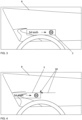
- Fig. 3 and Fig. 4 illustrate the effects of shifting the contents 3 shown by the head-up display device on the windscreen 8 of the motor vehicle according to the course of the road from the driver's perspective.
- Fig. 3 there is no shifting of the contents 3 according to the course of the road, ie the projected image is fixed at a certain distance in front of the motor vehicle 1.
- the displayed contents 3 appear offset from the road, which can unconsciously cause the driver to continue driving straight ahead when looking at the displayed contents instead of following the curve.
- the contents 3 are shifted according to the course of the road, as shown in Fig. 4 is indicated by the displacement vectors 50 shown.
- the displayed contents 3 appear essentially centered on the lane, which increases driving safety.
- the size of the space available for the displayed contents 3 is taken into account during the displacement.
- Fig. 4 you can see that the displayed content 3 just fits on the front screen 8. A shift further to the left would result in the displayed content 3 being partially cut off. To prevent this, the shift can be limited to a maximum value.
- Fig. 5 and Fig. 6 show examples of the contents generated by the image generation unit 6 of the head-up display device 3.
- Fig. 5 shows the contents 3 when driving straight ahead
- Fig. 6 the Contents 3 when cornering.
- the image generation unit 6 is, for example, the one already described in connection with Fig. 1
- the generated contents 3 in the present example are arranged centrally on the image generation unit 6.
- the generated contents 3 are arranged off-center on the image generation unit 6.
- the direction and size of the shift, which in Fig. 6 indicated by the displacement vectors 50 shown depend on the course of the road and, if applicable, on the optical beam path within the head-up display device.
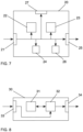
- Fig. 7 shows a simplified schematic representation of a first embodiment of a device 20 for controlling a display of a head-up display device for a motor vehicle.
- the device 20 has an input 21 for receiving data that allows a determination of the course of the road in front of the motor vehicle. This is in particular information on the driver's eye movements.
- An evaluation unit 22 determines the course of the road in front of the motor vehicle from the received data, with faster, short-term eye movements being suppressed with the aid of a filter.
- a control unit 23 then shifts the content displayed by the head-up display device in accordance with the determined course of the road. The shifting takes place in such a way that the content is displayed shifted in the direction of the curve when cornering.
- the shifting of the content displayed by the head-up display device can take place, for example, by rotating a mirror or a prism of the projection unit of the head-up display device or by shifting the displayed content on an image generation unit of the head-up display device.
- the image generation unit can be integrated into a windshield or a display surface of the motor vehicle or be part of the projection unit of the head-up display device.
- the data required for the shifting are provided via an output 25 of the device 20.
- the evaluation unit 22 and the control unit 23 can be controlled by a control unit 24. Settings of the evaluation unit 22, the control unit 23 or the control unit 24 can be changed via a user interface 27 if necessary.
- the data generated in the device 20 can also be stored in a memory 26 of the device 20, for example for later evaluation.
- the evaluation unit 22, the control unit 23 and the control unit 24 can be implemented as dedicated hardware, for example as integrated circuits.
- the input 21 and the output 25 can be implemented as separate interfaces or as a combined bidirectional interface.
- Fig. 8 shows a simplified schematic representation of a second embodiment of a device 30 for controlling a display of a head-up display device for a motor vehicle.
- the device 30 has a processor 32 and a memory 31.
- the device 30 is a computer or a control unit. Instructions are stored in the memory 31 which, when executed by the processor 32, cause the device 30 to carry out the steps according to one of the described methods.
- the instructions stored in the memory 31 thus embody a program which can be executed by the processor 32 and which implements the method according to the invention.
- the device has an input 33 for receiving information. Data generated by the processor 32 are made available via an output 34. In addition, they can be stored in the memory 31.
- the input 33 and the output 34 can be combined to form a bidirectional interface.
- the processor 32 may include one or more processing units, such as microprocessors, digital signal processors, or combinations thereof.
- the memories 26, 31 of the described embodiments can have both volatile and non-volatile memory areas and can comprise a wide variety of storage devices and storage media, for example hard disks, optical storage media or semiconductor memories.
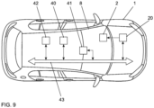
- Fig. 9 schematically shows a motor vehicle 1 in which a solution according to the invention is implemented.
- the motor vehicle has a head-up display device 2 with which information is displayed on the windshield 8 of the motor vehicle 1 or on an additional pane (not shown) arranged between the driver and the windshield 8.
- the head-up display device 2 is controlled by a device 20 for controlling the display of the head-up display device.
- the motor vehicle 1 has a navigation system 40 and an environmental sensor system 41, for example a camera system. From information on the driver's eye movements, the device 20 determines a road course in front of the motor vehicle 1 and controls the head-up display device 2 The transmission of data within the motor vehicle 1 takes place with the aid of a network 43 to which further control units 42 can be connected.
Landscapes
- Engineering & Computer Science (AREA)
- Chemical & Material Sciences (AREA)
- Mechanical Engineering (AREA)
- Transportation (AREA)
- Combustion & Propulsion (AREA)
- Remote Sensing (AREA)
- Radar, Positioning & Navigation (AREA)
- Physics & Mathematics (AREA)
- General Physics & Mathematics (AREA)
- Automation & Control Theory (AREA)
- Optics & Photonics (AREA)
- Instrument Panels (AREA)
- Fittings On The Vehicle Exterior For Carrying Loads, And Devices For Holding Or Mounting Articles (AREA)
Description
- Die vorliegende Erfindung betrifft ein Verfahren, eine Vorrichtung und ein computerlesbares Speichermedium mit Instruktionen zur Steuerung einer Anzeige einer Head-up-Display-Vorrichtung für ein Kraftfahrzeug. Die Erfindung betrifft weiterhin eine Head-up-Display-Vorrichtung für ein Kraftfahrzeug sowie ein Kraftfahrzeug, in dem eine solche Head-up-Display-Vorrichtung, ein erfindungsgemäßes Verfahren oder eine erfindungsgemäße Vorrichtung eingesetzt wird.
- Unter einem Head-up-Display bzw. einer Head-up-Display-Vorrichtung versteht man ein Anzeigesystem, bei dem der Nutzer seine Blickrichtung beibehalten kann, da die darzustellenden Inhalte in sein Sichtfeld eingeblendet werden. Während derartige Systeme aufgrund ihrer Komplexität und Kosten zunächst im Wesentlichen in der Luftfahrt Verwendung fanden, werden sie inzwischen auch im Automobilbereich in Großserie verbaut.
- Head-up-Displays bestehen im Allgemeinen aus einer bildgebenden Einheit, einem optischen Modul und einer Projektionsfläche. Die bildgebende Einheit erzeugt das Bild. Das optische Modul leitet das Bild auf die Projektionsfläche. Diese Fläche ist eine teilweise spiegelnde, lichtdurchlässige Scheibe. Der Benutzer sieht also die von der bildgebenden Einheit dargestellten Inhalte und gleichzeitig die reale Welt hinter der Scheibe. Als Projektionsfläche dient im Automobilbereich oftmals die Frontscheibe, deren gekrümmte Form bei der Darstellung berücksichtigt werden muss. Als Alternative wird zum Teil auch eine zusätzliche Kunststoffscheibe genutzt, die zwischen dem Fahrer und der Frontscheibe auf dem Armaturenbrett angeordnet ist.
- Typischerweise werden sowohl statische Informationen als auch kontaktanaloge Informationen dargestellt. Unter statischen Informationen werden solche Informationen verstanden, die sich immer an derselben Stelle im Blickfeld des Fahrers befinden. Beispiele sind die Fahrzeuggeschwindigkeit, Geschwindigkeitsbegrenzungen oder die Motordrehzahl. Kontaktanaloge Informationen werden dem Fahrer so in sein Blickfeld eingeblendet, dass sie ihm als fester Bestandteil der Umwelt erscheinen. Beispielsweise erscheint ein Navigationspfeil direkt auf der Straße.
- Vor diesem Hintergrund beschreibt die Druckschrift
DE 10 2014 001 270 A1 ein Head-up-Display für ein Kraftfahrzeug, bei dem bestimmte Wiedergabeeigenschaften der dargestellten Objekte von der Blickrichtung des Fahrers abhängen. Mittels einer ersten Sensorik werden Objekte in der Umgebung des Fahrzeuges erfasst. Mittels einer weiteren Sensorik wird die Blickrichtung des Fahrers bestimmt. Die detektierten Objekte werden nun so im Display eingeblendet, dass sie für den Fahrer im Wesentlichen deckungsgleich mit den tatsächlichen Objekten erscheinen, dass also eine kontaktanaloge Darstellung erreicht wird. - Die Druckschrift
DE 10 2014 226 860 A1 beschreibt ein Verfahren zum Betreiben eines Head-up-Displays eines Kraftfahrzeuges, bei dem Eigenschaften der Darstellung von der Blickrichtung des Fahrers abhängen. Mittels einer Sensorik wird die Blickrichtung des Fahrers bestimmt. Wenn der Fahrer in Richtung des Head-up-Displays blickt, wird die Darstellung so verändert, dass die darauf angezeigte Information für den Fahrer gut lesbar wird. Andernfalls befindet sich das Head-up-Display in einem Ruhezustand, in dem die Anzeige des Head-up-Displays kaum oder gar nicht vom Fahrer wahrgenommen wird. - Die Druckschrift
DE 10 2010 013 532 A1 beschreibt ein Verfahren zum selektiven Projizieren grafischer Bilder an eine transparente Frontscheiben-Head-up-Anzeige eines Fahrzeugs auf der Grundlage einer Notwendigkeit einer verbesserten Sicht. Bei dem Verfahren werden Informationseingänge überwacht, die eine Betriebsumgebung für das Fahrzeug beschreiben. Die Informationseingänge werden verarbeitet, um Anzeigeanforderungen zu erzeugen. Bei der Verarbeitung wird die Notwendigkeit einer verbesserten Sicht auf der Grundlage der Informationseingänge ermittelt. Die Anzeigeanforderungen werden auf der Grundlage der Informationseingänge und der Notwendigkeit einer verbesserten Sicht erzeugt. Auf der Grundlage der Anzeigeanforderungen werden die zu projizierenden grafischen Bilder erzeugt. Diese werden dann an die transparente Frontscheiben-Head-up-Anzeige projiziert. - Die Druckschrift
EP 1 783 531 A1 beschreibt eine Projektionsanzeige zur Erzeugung eines virtuellen Bildes in einem Fahrzeug. Die Projektionsanzeige umfasst eine Bilderzeugungseinheit, eine Projektionsfläche, eine Abbildungsoptik zur Projektion des virtuellen Bildes auf die Projektionsfläche, wobei die Projektionsfläche die Windschutzscheibe des Fahrzeugs ist, und eine Detektionseinheit zur Ermittlung einer Blickrichtung eines Fahrers des Fahrzeugs. Die Detektionseinheit beobachtet dabei den Fahrer über die Abbildungsoptik. - Die Druckschrift
DE 10 2005 035 412 A1 beschreibt eine Fahrerassistenzvorrichtung in einem Fahrzeug. Die Fahrerassistenzvorrichtung umfasst eine Erfassungseinrichtung zur Ermittlung eines Verlaufs einer Fahrbahn- und/oder Fahrspur vor dem Fahrzeug und eine Anzeige zur Darstellung eines Fahrbahn- und/oder Fahrspurverlaufs. Der Fahrbahn- und/oder Fahrspurverlauf wird in der Anzeige um ein vorgegebenes Maß enger als der Verlauf der ermittelten tatsächlichen Fahrbahn- und/oder Fahrspur dargestellt. - Die Druckschrift
DE 198 13 300 A1 beschreibt eine Anzeigevorrichtung für Kraftfahrzeuge. Die Anzeigevorrichtung umfasst ein Head-up-Display zum Projizieren eines virtuellen Bildes vor einer Windschutzscheibe des Kraftfahrzeuges. Die Position des virtuellen Bildes vor der Windschutzscheibe ist in Abhängigkeit wenigstens eines Fahrzustandsparameters veränderlich. Problematisch an der Verwendung einer Head-up-Display-Vorrichtung in einem Kraftfahrzeug kann es sein, dass der Fahrer durch den Blick auf die dargestellten Inhalte unbewusst dazu veranlasst werden kann, das Kraftfahrzeug in Blickrichtung zu steuern. - Es ist eine Aufgabe der Erfindung, verbesserte Lösungen für eine Head-up-Display-Vorrichtung für ein Kraftfahrzeug sowie die Steuerung einer Anzeige einer Head-up-Display-Vorrichtung für ein Kraftfahrzeug aufzuzeigen, die in einer höheren Sicherheit und einem größeren Komfort für den Fahrer des Kraftfahrzeuges resultieren.
- Diese Aufgabe wird durch ein Verfahren mit den Merkmalen des Anspruchs 1, durch eine Vorrichtung mit den Merkmalen des Anspruchs 6, durch ein computerlesbares Speichermedium mit Instruktionen gemäß Anspruch 11, durch eine Head-up-Display-Vorrichtung für ein Kraftfahrzeug gemäß Anspruch 12 sowie durch ein Kraftfahrzeug gemäß Anspruch 13 gelöst. Bevorzugte Ausgestaltungen der Erfindung sind Gegenstand der abhängigen Ansprüche.
- Der Begriff Computer ist dabei breit zu verstehen. Insbesondere umfasst er auch Steuergeräte und andere prozessorbasierte Datenverarbeitungsvorrichtungen.
- Gemäß einem weiteren Aspekt der Erfindung werden ein erfindungsgemäßes Verfahren oder eine erfindungsgemäße Vorrichtung in einer Head-up-Display-Vorrichtung für ein Kraftfahrzeug eingesetzt.
- Erfindungsgemäß erfolgt eine seitliche oder auch höhenbezogene, also horizontale oder vertikale Verschiebung der dargestellten Inhalte, d.h. des angezeigten Bildes, entsprechend dem vor dem Kraftfahrzeug liegenden Straßenverlauf. Statt ortsfest relativ zur Frontscheibe zu bleiben wird das Bild bei Kurvenfahrten dynamisch verlagert, um die Informationen im Blickfeld des Fahrers zu halten. Die Head-up-Display-Vorrichtung verändert dazu den Zielpunkt ihrer Projektion entsprechend der zu durchfahrenden Kurve, bei Berg- oder Talfahrt und anderen Fahrmanövern, bei denen die Sichtachse des Fahrers nicht mit einer ortsfesten Projektion auf der Windschutzscheibe übereinstimmt. In Head-up-Display-Vorrichtungen gemäß dem Stand der Technik erscheint das projizierte Bild in einer gewissen Entfernung vor dem Kraftfahrzeug fixiert. Das starr vor dem Kraftfahrzeug stehende Bild scheint z.B. bei einer Kurvenfahrt in den Bergen über dem Abgrund zu schweben, während der Blick des Fahrers eigentlich in die Kurve gerichtet sein sollte, um das Kraftfahrzeug zielgerichtet zu lenken. Die Projektion auf eine feste Position vor dem Fahrzeug auch bei einer Kurvenfahrt kann den Fahrer geradezu dazu verführen, beim Blick auf die dargestellten Inhalte weiter geradeaus zu fahren, anstatt der Kurve zu folgen. Bei Verwendung der erfindungsgemäßen Lösung schaut der Fahrer auch beim Blick auf die dargestellten Inhalte immer in die zukünftige Fahrtrichtung, was zu einer erhöhten Sicherheit führt. Erfindungsgemäß wird der Straßenverlauf vor dem Kraftfahrzeug aus Augenbewegungen des Fahrers bestimmt. Unter der Annahme, dass der Fahrer in die geplante Fahrtrichtung schaut, kann die Position der dargestellten Inhalte entsprechend der Blickrichtung angepasst werden. Dabei werden mit Hilfe eines Filters schnellere, kurzzeitige Augenbewegungen unterdrückt. Head-up-Display-Vorrichtungen sind heute oftmals mit einer Sensorik zur Erfassung von Augen- oder Kopfbewegungen gekoppelt, so dass auf die vorhandene Sensorik zurückgegriffen werden kann.
- Gemäß einem Aspekt der Erfindung werden die von der Head-up-Display-Vorrichtung dargestellten Inhalte derart verschoben, dass der Inhalt für den Fahrer zentriert zu seiner Fahrspur erscheint. Auf diese Weise wird der Blick des Fahrers quasi in die Fahrspur hinein gelenkt. Der Fahrer schaut also genau in die Richtung, in die er auch fahren muss, so dass er dem vor ihm liegenden Fahrweg seine volle Aufmerksamkeit widmen kann. Vorzugsweise kann der Nutzer einen Maximalwert für die Verschiebung festlegen. Ebenso ist es möglich, dass der Benutzer die Abhängigkeit der Verschiebung vom Straßenverlauf festlegen oder das Verschieben ganz abschalten kann. Falls der Benutzer beispielsweise größere Verschiebungen als unangenehm empfindet, kann er einstellen, dass die dargestellten Inhalte zwar generell dem Straßenverlauf folgen, aber nur in einem geringeren Ausmaß. In diesem Fall erscheinen dargestellten Inhalte nicht zentriert zur Fahrspur. Dennoch wird der Blick des Fahrers zumindest noch zu einem gewissen Maß in die Fahrspur hinein gelenkt.
- Gemäß einem Aspekt der Erfindung erfolgt das Verschieben der von der Head-up-Display-Vorrichtung dargestellten Inhalte durch eine Drehung eines Spiegels oder eines Prismas einer Projektionseinheit der Head-up-Display-Vorrichtung. In einer Head-up-Display-Vorrichtung werden die dargestellten Inhalte durch eine Projektionseinheit erzeugt und mit Hilfe von Spiegeln oder Prismen auf die Frontscheibe projiziert. In der Regel ist zumindest eine dieser optischen Komponenten beweglich gelagert, um die Position der dargestellten Inhalte auf der Frontscheibe anpassen zu können. Dieser Umstand kann genutzt werden, um durch die Drehung der optischen Komponente die dargestellten Inhalte entsprechend dem Straßenverlauf zu positionieren. Alternativ kann die Verschiebung auch durch Verschieben der dargestellten Inhalte auf einer Bilderzeugungseinheit der Head-up-Display-Vorrichtung erfolgen. Die Bilderzeugungseinheit kann dabei Bestandteil der Projektionseinheit der Head-up-Display-Vorrichtung sein, z.B. in Form eines Matrix-Displays. Die Bilderzeugungseinheit kann aber auch in die Frontscheibe oder eine Anzeigefläche des Kraftfahrzeuges integriert sein, beispielsweise in Form einer flexiblen Bildschirm-Folie. Ein Beispiel für eine solche flexible Bildschirm-Folie sind OLED-Display-Folien (OLED: Organic Light-Emitting Diode, organische Leuchtdiode). Hierbei werden die Inhalte direkt auf dem in die Windschutzscheibe integrierten Display vertikal beziehungsweise horizontal verschoben und optimiert.
- Vorzugsweise werden ein erfindungsgemäßes Verfahren, eine erfindungsgemäße Vorrichtung oder eine erfindungsgemäße Head-up-Display-Vorrichtung in einem autonom oder manuell gesteuerten Fahrzeug, insbesondere einem Kraftfahrzeug, eingesetzt.
- Weitere Merkmale der vorliegenden Erfindung werden aus der nachfolgenden Beschreibung und den angehängten Ansprüchen in Verbindung mit den Figuren ersichtlich.
- Fig. 1
- zeigt schematisch eine Head-up-Display-Vorrichtung für ein Kraftfahrzeug;
- Fig. 2
- zeigt schematisch ein Verfahren zur Steuerung einer Anzeige einer Head-up-Display-Vorrichtung für ein Kraftfahrzeug;
- Fig. 3
- zeigt die von der Head-up-Display-Vorrichtung dargestellten Inhalte aus Sicht des Fahrers ohne eine Verschiebung entsprechend dem Straßenverlauf;
- Fig. 4
- zeigt die von der Head-up-Display-Vorrichtung dargestellten Inhalte aus Sicht des Fahrers mit einer Verschiebung entsprechend dem Straßenverlauf;
- Fig. 5
- zeigt die von einer Bilderzeugungseinheit der Head-up-Display-Vorrichtung generierten Inhalte bei einer Geradeausfahrt;
- Fig. 6
- zeigt die von einer Bilderzeugungseinheit der Head-up-Display-Vorrichtung generierten Inhalte bei einer Kurvenfahrt;
- Fig. 7
- zeigt eine erste Ausführungsform einer Vorrichtung zur Steuerung einer Anzeige einer Head-up-Display-Vorrichtung für ein Kraftfahrzeug;
- Fig. 8
- zeigt eine zweite Ausführungsform einer Vorrichtung zur Steuerung einer Anzeige einer Head-up-Display-Vorrichtung für ein Kraftfahrzeug; und
- Fig. 9
- stellt schematisch ein Kraftfahrzeug dar, in dem eine erfindungsgemäße Lösung realisiert ist.
- Zum besseren Verständnis der Prinzipien der vorliegenden Erfindung werden nachfolgend Ausführungsformen der Erfindung anhand der Figuren detaillierter erläutert. Es versteht sich, dass sich die Erfindung nicht auf diese Ausführungsformen beschränkt und dass die beschriebenen Merkmale auch kombiniert oder modifiziert werden können, ohne den Schutzbereich der Erfindung zu verlassen, wie er in den angehängten Ansprüchen definiert ist.
-
Fig. 1 zeigt schematisch eine Head-up-Display-Vorrichtung 2 für ein Kraftfahrzeug 1, mit deren Hilfe Inhalte 3 auf einer Frontscheibe 8 des Kraftfahrzeuges angezeigt werden können. Die dargestellten Inhalte 3 werden durch eine Projektionseinheit 4 erzeugt und mit Hilfe von Spiegeln 5 auf die Frontscheibe 8 projiziert. In der Regel ist einer der Spiegel 5 beweglich gelagert, um die Position der dargestellten Inhalte auf der Frontscheibe 8 anpassen zu können. Typischerweise erfolgt die Projektion dabei in einen Bereich der Frontscheibe 8 oberhalb des Lenkrades 7. Die Projektionseinheit 4 umfasst eine Bilderzeugungseinheit 6, beispielsweise eine Kombination aus einer LED-Matrix (LED: Light-Emitting Diode, Leuchtdiode) und einem TFT-Farbdisplay (TFT-Display: Thin-Film Transistor-Display, Anzeige mit Dünnschichttransistor-Ansteuerung). Die Head-up-Display-Vorrichtung 2 ist in einem Armaturenbrett 9 des Kraftfahrzeuges 1 verbaut. -
Fig. 2 zeigt schematisch ein Verfahren zur Steuerung einer Anzeige einer Head-up-Display-Vorrichtung für ein Kraftfahrzeug. In einem ersten Schritt wird aus Augenbewegungen des Fahrers ein Straßenverlauf vor dem Kraftfahrzeug bestimmt 10, wobei mit Hilfe eines Filters schnellere, kurzzeitige Augenbewegungen unterdrückt werden. Die von der Head-up-Display-Vorrichtung dargestellten Inhalte werden dann entsprechend dem bestimmten Straßenverlauf verschoben 11. Das Verschieben erfolgt dabei derart, dass zumindest ein Inhalt, der keinen direkten Bezug zur Umwelt hat, bei Kurvenfahrten in Kurvenrichtung verschoben dargestellt wird. Vorzugsweise werden die dargestellten Inhalte derart verschoben, dass der Inhalt, der keinen direkten Bezug zur Umwelt hat, für den Fahrer zentriert zu seiner Fahrspur erscheint, seinen Blick also quasi in die Fahrspur hinein lenkt. Das Verschieben der von der Head-up-Display-Vorrichtung dargestellten Inhalte kann beispielsweise durch eine Drehung eines Spiegels oder eines Prismas der Projektionseinheit der Head-up-Display-Vorrichtung oder durch Verschieben der dargestellten Inhalte auf einer Bilderzeugungseinheit der Head-up-Display-Vorrichtung erfolgen. Die Bilderzeugungseinheit kann dabei in eine Frontscheibe oder eine Anzeigefläche des Kraftfahrzeuges integriert sein oder Bestandteil der Projektionseinheit der Head-up-Display-Vorrichtung sein. -
Fig. 3 und Fig. 4 verdeutlichen die Auswirkungen einer Verschiebung der von der Head-up-Display-Vorrichtung auf der Frontscheibe 8 des Kraftfahrzeuges dargestellten Inhalte 3 entsprechend dem Straßenverlauf aus Sicht des Fahrers. InFig. 3 ) erfolgt keine Verschiebung der Inhalte 3 entsprechend dem Straßenverlauf, d.h. das projizierte Bild ist in einer gewissen Entfernung vor dem Kraftfahrzeug 1 fixiert. Wie man sieht erscheinen die dargestellten Inhalte 3 versetzt zur Straße, was den Fahrer unbewusst dazu veranlassen kann, beim Blick auf die dargestellten Inhalte weiter geradeaus zu fahren, anstatt der Kurve zu folgen. InFig. 4 ) erfolgt hingegen eine Verschiebung der Inhalte 3 entsprechend dem Straßenverlauf, wie dies inFig. 4 durch die gezeigten Verschiebungsvektoren 50 angedeutet ist. Die dargestellten Inhalte 3 erscheinen in diesem Fall im Wesentlichen zentriert zur Fahrspur, wodurch sich die Fahrsicherheit erhöht. Vorzugsweise wird bei der Verschiebung die Größe des für die dargestellten Inhalte 3 verfügbaren Platzes berücksichtigt. InFig. 4 kann man erkennen, dass die dargestellten Inhalte 3 gerade noch auf der Frontscheibe 8 Platz finden. Eine Verschiebung noch weiter nach links würde dazu führen, dass die dargestellten Inhalte 3 teilweise abgeschnitten würden. Um dies zu verhindern kann die Verschiebung auf einen Maximalwert begrenzt werden. -
Fig. 5 und Fig. 6 zeigen Beispiele für die von der Bilderzeugungseinheit 6 der Head-up-Display-Vorrichtung generierten Inhalte 3.Fig. 5 zeigt die Inhalte 3 bei einer Geradeausfahrt,Fig. 6 die Inhalte 3 bei einer Kurvenfahrt. Bei der Bilderzeugungseinheit 6 handelt es sich beispielsweise um die bereits in Zusammenhang mitFig. 1 genannte Kombination aus einer LED-Matrix und einem TFT-Farbdisplay, die in der Projektionseinheit der Head-up-Display-Vorrichtung verbaut ist, oder um eine in die Frontscheibe oder eine Anzeigefläche des Kraftfahrzeuges integrierte Bilderzeugungseinheit 6, z.B. eine flexible Bildschirm-Folie. Während der Geradeausfahrt sind die generierten Inhalte 3 im vorliegenden Beispiel mittig auf der Bilderzeugungseinheit 6 angeordnet. Bei einer Kurve im Straßenverlauf vor dem Fahrzeug sind die generierten Inhalte 3 außermittig auf der Bilderzeugungseinheit 6 angeordnet. Richtung und Größe der Verschiebung, die inFig. 6 durch die gezeigten Verschiebungsvektoren 50 angedeutet sind, hängen dabei vom Straßenverlauf und gegebenenfalls vom optischen Strahlengang innerhalb der Head-up-Display-Vorrichtung ab. -
Fig. 7 zeigt eine vereinfachte schematische Darstellung einer ersten Ausführungsform einer Vorrichtung 20 zur Steuerung einer Anzeige einer Head-up-Display-Vorrichtung für ein Kraftfahrzeug. Die Vorrichtung 20 hat einen Eingang 21 zum Empfangen von Daten, die eine Bestimmung eines Straßenverlaufs vor dem Kraftfahrzeug erlauben. Dabei handelt es sich insbesondere um Informationen zu Augenbewegungen des Fahrers. Aus den empfangenen Daten bestimmt eine Auswerteeinheit 22 den Straßenverlauf vor dem Kraftfahrzeug, wobei mit Hilfe eines Filters schnellere, kurzzeitige Augenbewegungen unterdrückt werden. Eine Steuerungseinheit 23 verschiebt dann die von der Head-up-Display-Vorrichtung dargestellten Inhalte entsprechend dem bestimmten Straßenverlauf. Das Verschieben erfolgt dabei derart, dass der Inhalt bei Kurvenfahrten in Kurvenrichtung verschoben dargestellt wird. Das Verschieben der von der Head-up-Display-Vorrichtung dargestellten Inhalte kann beispielsweise durch eine Drehung eines Spiegels oder eines Prismas der Projektionseinheit der Head-up-Display-Vorrichtung oder durch Verschieben der dargestellten Inhalte auf einer Bilderzeugungseinheit der Head-up-Display-Vorrichtung erfolgen. Die Bilderzeugungseinheit kann dabei in eine Frontscheibe oder eine Anzeigefläche des Kraftfahrzeuges integriert sein oder Bestandteil der Projektionseinheit der Head-up-Display-Vorrichtung sein. Die für das Verschieben notwendigen Daten werden über einen Ausgang 25 der Vorrichtung 20 bereitgestellt. Die Auswerteeinheit 22 und die Steuerungseinheit 23 können von einer Kontrolleinheit 24 gesteuert werden. Über eine Benutzerschnittstelle 27 können gegebenenfalls Einstellungen der Auswerteeinheit 22, der Steuerungseinheit 23 oder der Kontrolleinheit 24 geändert werden. Die in der Vorrichtung 20 anfallenden Daten können zudem in einem Speicher 26 der Vorrichtung 20 abgelegt werden, beispielsweise für eine spätere Auswertung. Die Auswerteeinheit 22, die Steuerungseinheit 23 sowie die Kontrolleinheit 24 können als dezidierte Hardware realisiert sein, beispielsweise als integrierte Schaltungen. - Natürlich können sie aber auch teilweise oder vollständig kombiniert oder als Software implementiert werden, die auf einem geeigneten Prozessor läuft. Der Eingang 21 und der Ausgang 25 können als getrennte Schnittstellen oder als eine kombinierte bidirektionale Schnittstelle implementiert sein.
-
Fig. 8 zeigt eine vereinfachte schematische Darstellung einer zweiten Ausführungsform einer Vorrichtung 30 zur Steuerung einer Anzeige einer Head-up-Display-Vorrichtung für ein Kraftfahrzeug. Die Vorrichtung 30 weist einen Prozessor 32 und einen Speicher 31 auf. Beispielsweise handelt es sich bei der Vorrichtung 30 um einen Computer oder ein Steuergerät. Im Speicher 31 sind Instruktionen abgelegt, die die Vorrichtung 30 bei Ausführung durch den Prozessor 32 veranlassen, die Schritte gemäß einem der beschriebenen Verfahren auszuführen. Die im Speicher 31 abgelegten Instruktionen verkörpern somit ein durch den Prozessor 32 ausführbares Programm, welches das erfindungsgemäße Verfahren realisiert. Die Vorrichtung hat einen Eingang 33 zum Empfangen von Informationen. Vom Prozessor 32 generierte Daten werden über einen Ausgang 34 bereitgestellt. Darüber hinaus können sie im Speicher 31 abgelegt werden. Der Eingang 33 und der Ausgang 34 können zu einer bidirektionalen Schnittstelle zusammengefasst sein. - Der Prozessor 32 kann eine oder mehrere Prozessoreinheiten umfassen, beispielsweise Mikroprozessoren, digitale Signalprozessoren oder Kombinationen daraus.
- Die Speicher 26, 31 der beschriebenen Ausführungsformen können sowohl volatile als auch nichtvolatile Speicherbereiche aufweisen und unterschiedlichste Speichergeräte und Speichermedien umfassen, beispielsweise Festplatten, optische Speichermedien oder Halbleiterspeicher.
-
Fig. 9 stellt schematisch ein Kraftfahrzeug 1 dar, in dem eine erfindungsgemäße Lösung realisiert ist. Das Kraftfahrzeug weist eine Head-up-Display-Vorrichtung 2 auf, mit der Informationen auf der Frontscheibe 8 des Kraftfahrzeuges 1 oder auf einer zwischen Fahrer und Frontscheibe 8 angeordneten zusätzlichen Scheibe (nicht gezeigt) dargestellt werden. Die Head-up-Display-Vorrichtung 2 wird von einer Vorrichtung 20 zur Steuerung der Anzeige der Head-up-Display-Vorrichtung angesteuert. Zusätzlich weist das Kraftfahrzeug 1 ein Navigationssystem 40 und eine Umgebungssensorik 41 auf, beispielsweise ein Kamerasystem. Aus Informationen zu Augenbewegungen des Fahrers ermittelt die Vorrichtung 20 einen Straßenverlauf vor dem Kraftfahrzeug 1 und steuert die Head-up-Display-Vorrichtung 2 entsprechend an. Die Übertragung der Daten innerhalb des Kraftfahrzeuges 1 erfolgt mit Hilfe eines Netzwerkes 43, an das weitere Steuergeräte 42 angeschlossen sein können. -
- 1
- Kraftfahrzeug
- 2
- Head-up-Display-Vorrichtung
- 3
- Dargestellte Inhalte
- 4
- Projektionseinheit
- 5
- Spiegel
- 6
- Bilderzeugungseinheit
- 7
- Lenkrad
- 8
- Frontscheibe
- 9
- Armaturenbrett
- 10
- Bestimmen eines Straßenverlaufs vor dem Kraftfahrzeug
- 11
- Verschieben der dargestellten Inhalte entsprechend dem Straßenverlauf
- 20
- Vorrichtung
- 21
- Eingang
- 22
- Auswerteeinheit
- 23
- Steuerungseinheit
- 24
- Kontrolleinheit
- 25
- Ausgang
- 26
- Speicher
- 27
- Benutzerschnittstelle
- 30
- Vorrichtung
- 31
- Speicher
- 32
- Prozessor
- 33
- Eingang
- 34
- Ausgang
- 40
- Navigationssystem
- 41
- Umgebungssensorik
- 42
- Steuergerät
- 43
- Netzwerk
- 50
- Verschiebungsvektor
Claims (13)
- Verfahren zur Steuerung einer Anzeige einer Head-up-Display-Vorrichtung (2) für ein Kraftfahrzeug (1), mit den Schritten:- Generieren von Inhalten (3) für eine Darstellung durch die Head-up-Display-Vorrichtung (2), wobei die generierten Inhalte (3) zumindest eine statische Information beinhalten; und- Bestimmen (10) eines Straßenverlaufs vor dem Kraftfahrzeug (1);- Verschieben (11) der von der Head-up-Display-Vorrichtung (2) dargestellten Inhalte (3) entsprechend dem bestimmten Straßenverlauf;dadurch gekennzeichnet, dass der Straßenverlauf aus Augenbewegungen des Fahrers bestimmt wird (10), wobei mit Hilfe eines Filters schnellere, kurzzeitige Augenbewegungen unterdrückt werden;und dass die dargestellten Inhalte (3) derart verschoben werden, dass sie bei Kurvenfahrten in Kurvenrichtung verschoben dargestellt werden.
- Verfahren gemäß Anspruch 1, wobei die von der Head-up-Display-Vorrichtung (2) dargestellten Inhalte (3) derart verschoben werden, dass die statische Information für den Fahrer zentriert zu seiner Fahrspur erscheint.
- Verfahren gemäß Anspruch 1, wobei durch den Fahrer ein Maximalwert für die Verschiebung festlegbar ist.
- Verfahren gemäß einem der vorherigen Ansprüche, wobei das Verschieben der von der Head-up-Display-Vorrichtung (2) dargestellten Inhalte (3) durch eine Drehung eines Spiegels (5) oder eines Prismas einer Projektionseinheit (4) der Head-up-Display-Vorrichtung (2) oder durch Verschieben der dargestellten Inhalte auf einer Bilderzeugungseinheit (6) der Head-up-Display-Vorrichtung (2) erfolgt.
- Verfahren gemäß Anspruch 4, wobei die Bilderzeugungseinheit (6) in eine Frontscheibe (8) oder eine Anzeigefläche des Kraftfahrzeuges (1) integriert ist oder Bestandteil der Projektionseinheit (4) der Head-up-Display-Vorrichtung (2) ist.
- Vorrichtung (20) zur Steuerung einer Anzeige einer Head-up-Display-Vorrichtung (2) für ein Kraftfahrzeug (1), wobei die Vorrichtung (20) aufweist:- eine Bilderzeugungseinheit (6) zum Generieren von Inhalten (3) für eine Darstellung durch die Head-up-Display-Vorrichtung (2), wobei die generierten Inhalte (3) zumindest eine statische Information beinhalten; und- eine Auswerteeinheit (22) zum Bestimmen (10) eines Straßenverlaufs vor dem Kraftfahrzeug (1); und- eine Steuerungseinheit (23) zum Verschieben (11) der von der Head-up-Display-Vorrichtung (2) dargestellten Inhalte (3) entsprechend dem bestimmten Straßenverlauf; dadurch gekennzeichnet, dass die Auswerteeinheit (22) eingerichtet ist, den Straßenverlauf aus Augenbewegungen des Fahrers zu bestimmen (10), wobei mit Hilfe eines Filters schnellere, kurzzeitige Augenbewegungen unterdrückt werden;und dass die Steuerungseinheit (23) eingerichtet ist, die dargestellten Inhalte (3) derart zu verschieben, dass sie bei Kurvenfahrten in Kurvenrichtung verschoben dargestellt werden.
- Vorrichtung (20) gemäß Anspruch 6, wobei die Steuerungseinheit (23) eingerichtet ist, die von der Head-up-Display-Vorrichtung (2) dargestellten Inhalte (3) derart zu verschieben, dass die statische Information für den Fahrer zentriert zu seiner Fahrspur erscheint.
- Vorrichtung (20) gemäß Anspruch 6, wobei durch den Fahrer ein Maximalwert für die Verschiebung festlegbar ist.
- Vorrichtung (20) gemäß einem der Ansprüche 6 bis 8, wobei die Steuerungseinheit (23) eingerichtet ist, das Verschieben der von der Head-up-Display-Vorrichtung (2) dargestellten Inhalte (3) durch eine Drehung eines Spiegels (5) oder eines Prismas einer Projektionseinheit (4) der Head-up-Display-Vorrichtung (2) oder durch Verschieben der dargestellten Inhalte auf einer Bilderzeugungseinheit (6) der Head-up-Display-Vorrichtung (2) zu realisieren.
- Vorrichtung (20) gemäß Anspruch 9, wobei die Bilderzeugungseinheit (6) in eine Frontscheibe (8) oder eine Anzeigefläche des Kraftfahrzeuges (1) integriert ist oder Bestandteil der Projektionseinheit (4) der Head-up-Display-Vorrichtung (2) ist.
- Computerlesbares Speichermedium mit Instruktionen, die bei Ausführung durch einen Computer den Computer zur Ausführung der Schritte eines Verfahrens gemäß einem der Ansprüche 1 bis 5 zur Steuerung einer Anzeige einer Head-up-Display-Vorrichtung (2) für ein Kraftfahrzeug (1) veranlassen.
- Head-up-Display-Vorrichtung (2) für ein Kraftfahrzeug (1), dadurch gekennzeichnet, dass sie eine Vorrichtung (20) gemäß einem der Ansprüche 6 bis 10 aufweist oder eingerichtet ist, ein Verfahren gemäß einem der Ansprüche 1 bis 5 zur Steuerung einer Anzeige der Head-up-Display-Vorrichtung (2) auszuführen.
- Kraftfahrzeug (40), dadurch gekennzeichnet, dass es eine Head-up-Display-Vorrichtung (2) gemäß Anspruch 12 oder eine Vorrichtung (20) gemäß einem der Ansprüche 6 bis 10 aufweist oder eingerichtet ist, ein Verfahren gemäß einem der Ansprüche 1 bis 5 zur Steuerung einer Anzeige einer Head-up-Display-Vorrichtung (2) auszuführen.
Applications Claiming Priority (2)
| Application Number | Priority Date | Filing Date | Title |
|---|---|---|---|
| DE102016225639.4A DE102016225639A1 (de) | 2016-12-20 | 2016-12-20 | Head-up-Display-Vorrichtung für ein Kraftfahrzeug, Verfahren, Vorrichtung und computerlesbares Speichermedium mit Instruktionen zur Steuerung einer Anzeige einer Head-up-Display-Vorrichtung |
| PCT/EP2017/076373 WO2018114078A1 (de) | 2016-12-20 | 2017-10-16 | Head-up-display-vorrichtung für ein kraftfahrzeug, verfahren, vorrichtung und computerlesbares speichermedium mit instruktionen zur steuerung einer anzeige einer head-up-display-vorrichtung |
Publications (2)
| Publication Number | Publication Date |
|---|---|
| EP3559725A1 EP3559725A1 (de) | 2019-10-30 |
| EP3559725B1 true EP3559725B1 (de) | 2024-12-18 |
Family
ID=60201538
Family Applications (1)
| Application Number | Title | Priority Date | Filing Date |
|---|---|---|---|
| EP17792002.2A Active EP3559725B1 (de) | 2016-12-20 | 2017-10-16 | Head-up-display-vorrichtung für ein kraftfahrzeug, verfahren, vorrichtung und computerlesbares speichermedium mit instruktionen zur steuerung einer anzeige einer head-up-display-vorrichtung |
Country Status (6)
| Country | Link |
|---|---|
| US (1) | US11307047B2 (de) |
| EP (1) | EP3559725B1 (de) |
| KR (1) | KR20190094461A (de) |
| CN (1) | CN110249253A (de) |
| DE (1) | DE102016225639A1 (de) |
| WO (1) | WO2018114078A1 (de) |
Families Citing this family (7)
| Publication number | Priority date | Publication date | Assignee | Title |
|---|---|---|---|---|
| DE102019206749A1 (de) | 2019-05-09 | 2020-11-12 | Volkswagen Aktiengesellschaft | Mensch-Maschine-Interaktion in einem Kraftfahrzeug |
| KR102871421B1 (ko) | 2020-08-18 | 2025-10-15 | 삼성전자주식회사 | 컨텐츠를 시각화하는 장치 및 방법 |
| DE102020212520B3 (de) * | 2020-10-05 | 2021-10-21 | Volkswagen Aktiengesellschaft | Horizontale Positionsfestlegung für das Einblenden virtueller Objekte bei einer Head-Up-Displayeinrichtung |
| KR20240155977A (ko) | 2020-12-15 | 2024-10-29 | 양쯔 메모리 테크놀로지스 씨오., 엘티디. | Nand 메모리 동작을 위한 아키텍처 및 방법 |
| DE102021211139B3 (de) | 2021-10-04 | 2023-03-16 | Volkswagen Aktiengesellschaft | Verfahren zur Steuerung einer Anzeigeeinrichtung und Fahrzeug mit einer Anzeigeeinrichtung |
| DE102021213332A1 (de) * | 2021-11-26 | 2023-06-01 | Continental Automotive Technologies GmbH | Verfahren, Computerprogramm und Vorrichtung zum Steuern einer Augmented-Reality-Anzeigevorrichtung |
| DE102022125615B3 (de) | 2022-10-05 | 2023-11-30 | Dr. Ing. H.C. F. Porsche Aktiengesellschaft | Verfahren zur Visualisierung von optischen Informationen sowie Fahrzeug |
Family Cites Families (27)
| Publication number | Priority date | Publication date | Assignee | Title |
|---|---|---|---|---|
| JP3259475B2 (ja) * | 1993-10-27 | 2002-02-25 | ミノルタ株式会社 | 距離測定装置 |
| DE19813300C2 (de) * | 1998-03-26 | 2003-12-11 | Bosch Gmbh Robert | Anzeigevorrichtung |
| JP2001301486A (ja) | 2000-04-18 | 2001-10-31 | Honda Motor Co Ltd | 車両用ヘッドアップディスプレイ装置 |
| JP4698002B2 (ja) | 2000-07-11 | 2011-06-08 | マツダ株式会社 | 車両の表示装置 |
| DE10131720B4 (de) * | 2001-06-30 | 2017-02-23 | Robert Bosch Gmbh | Head-Up Display System und Verfahren |
| JP2006217447A (ja) * | 2005-02-07 | 2006-08-17 | Yazaki Corp | 車両用表示装置 |
| DE102005035412A1 (de) * | 2005-07-28 | 2007-02-01 | Robert Bosch Gmbh | Fahrerassistenzvorrichtung |
| DE102005052424A1 (de) * | 2005-11-03 | 2007-05-10 | Robert Bosch Gmbh | Projektionsanzeige |
| DE102007058295A1 (de) * | 2007-12-05 | 2009-06-10 | Audi Ag | Anzeigeeinrichtung für Kraftfahrzeug |
| JP5196252B2 (ja) * | 2008-06-26 | 2013-05-15 | 株式会社アドヴィックス | 車両制御装置 |
| JP4702437B2 (ja) | 2008-11-25 | 2011-06-15 | トヨタ自動車株式会社 | 車両用表示装置 |
| JP2010215194A (ja) | 2009-03-19 | 2010-09-30 | Hyundai Motor Co Ltd | 車載機器の操作装置 |
| US8704653B2 (en) * | 2009-04-02 | 2014-04-22 | GM Global Technology Operations LLC | Enhanced road vision on full windshield head-up display |
| KR20120113579A (ko) | 2011-04-05 | 2012-10-15 | 현대자동차주식회사 | 길안내 정보의 윈드쉴드 표시 장치 및 그 방법 |
| US10120438B2 (en) * | 2011-05-25 | 2018-11-06 | Sony Interactive Entertainment Inc. | Eye gaze to alter device behavior |
| KR101921969B1 (ko) | 2012-02-01 | 2018-11-28 | 한국전자통신연구원 | 차량용 증강현실 헤드업 디스플레이 장치 및 방법 |
| DE102012001951A1 (de) * | 2012-02-02 | 2013-08-08 | Daimler Ag | Anzeigevorrichtung für ein Fahrzeug und Verfahren zum Betreiben einer Anzeigevorrichtung |
| JP5492962B2 (ja) * | 2012-09-28 | 2014-05-14 | 富士重工業株式会社 | 視線誘導システム |
| JPWO2014174575A1 (ja) | 2013-04-22 | 2017-02-23 | トヨタ自動車株式会社 | 車両用ヘッドアップディスプレイ装置 |
| JP6241093B2 (ja) * | 2013-06-28 | 2017-12-06 | アイシン・エィ・ダブリュ株式会社 | ヘッドアップディスプレイ装置 |
| JP6094437B2 (ja) | 2013-09-24 | 2017-03-15 | アイシン・エィ・ダブリュ株式会社 | ヘッドアップディスプレイ装置 |
| DE102014001270A1 (de) * | 2014-01-31 | 2015-08-06 | Infineon Technologies Ag | Verfahren und System zur Berechnung von Codewörtern für geschützte Datenübertragungen |
| FR3027418B1 (fr) | 2014-10-20 | 2020-07-31 | Peugeot Citroen Automobiles Sa | Dispositif de controle de desactivation d’un systeme de surveillance de la trajectoire d’un vehicule, en fonction de la direction d’observation des yeux du conducteur |
| JP6377508B2 (ja) | 2014-11-27 | 2018-08-22 | パイオニア株式会社 | 表示装置、制御方法、プログラム、及び記憶媒体 |
| DE102014226860A1 (de) * | 2014-12-22 | 2016-06-23 | Robert Bosch Gmbh | Verfahren zum Betreiben eines Head-up-Displays, Anzeigevorrichtung, Fahrzeug |
| JP6512475B2 (ja) | 2015-04-30 | 2019-05-15 | 株式会社リコー | 情報提供装置、情報提供方法及び情報提供用制御プログラム |
| DE202015104499U1 (de) * | 2015-06-08 | 2016-09-09 | Denso Corporation | Head-Up Display mit situationsbasierter Anpassung der Darstellung von virtuellen Bildinhalten |
-
2016
- 2016-12-20 DE DE102016225639.4A patent/DE102016225639A1/de not_active Ceased
-
2017
- 2017-10-16 US US16/471,487 patent/US11307047B2/en active Active
- 2017-10-16 CN CN201780084936.9A patent/CN110249253A/zh active Pending
- 2017-10-16 EP EP17792002.2A patent/EP3559725B1/de active Active
- 2017-10-16 WO PCT/EP2017/076373 patent/WO2018114078A1/de not_active Ceased
- 2017-10-16 KR KR1020197021326A patent/KR20190094461A/ko not_active Ceased
Also Published As
| Publication number | Publication date |
|---|---|
| CN110249253A (zh) | 2019-09-17 |
| KR20190094461A (ko) | 2019-08-13 |
| US20190316928A1 (en) | 2019-10-17 |
| WO2018114078A1 (de) | 2018-06-28 |
| EP3559725A1 (de) | 2019-10-30 |
| DE102016225639A1 (de) | 2018-07-05 |
| US11307047B2 (en) | 2022-04-19 |
Similar Documents
| Publication | Publication Date | Title |
|---|---|---|
| EP3559725B1 (de) | Head-up-display-vorrichtung für ein kraftfahrzeug, verfahren, vorrichtung und computerlesbares speichermedium mit instruktionen zur steuerung einer anzeige einer head-up-display-vorrichtung | |
| EP3765324B1 (de) | Verfahren, vorrichtung und computerlesbares speichermedium mit instruktionen zur steuerung einer anzeige einer augmented-reality-display-vorrichtung für ein kraftfahrzeug | |
| DE10131720B4 (de) | Head-Up Display System und Verfahren | |
| EP3658976B1 (de) | Verfahren zum bereitstellen einer anzeige in einem kraftfahrzeug, sowie kraftfahrzeug | |
| DE102009004432B4 (de) | Kraftfahrzeuganzeigevorrichtung zum Anzeigen eines ein vorderes Hindernis umkreisenden Bildflecks | |
| DE102018129741A1 (de) | Vorrichtung und Verfahren zum Steuern einer Anzeige eines Fahrzeugs | |
| DE102017216774B4 (de) | Verfahren, Vorrichtung, computerlesbares Speichermedium und Kraftfahrzeug mit Instruktionen zur Steuerung einer Anzeige einer Augmented-Reality-Head-up-Display-Vorrichtung für ein Kraftfahrzeug | |
| DE102014214516A1 (de) | Vorrichtung und Verfahren zur Wiedergabe von Daten in einer erweiterten Realität für einen Insassen eines Fahrzeugs | |
| DE102013016242A1 (de) | Verfahren und Vorrichtung zur Unterstützung mindestens eines Fahrassistenzsystems | |
| DE102009045169A1 (de) | Anzeigevorrichtung für ein Fahrzeug und Verfahren zur Darstellung von Bildinformation in einem Fahrzeug | |
| EP3922501B1 (de) | Steuerung einer anzeige einer augmented-reality-head-up-display-vorrichtung für ein fortbewegungsmittel | |
| DE102017220268B4 (de) | Erkennung und Visualisierung von Systemunsicherheit bei der Darstellung augmentierter Bildinhalte in Head-Up-Displays | |
| DE102018201768B4 (de) | Verfahren zum Anzeigen von Informationen in einem Head-Up-Display eines Fahrzeugs, Anzeigesystem für ein Fahrzeug und Fahrzeug mit einem Anzeigesystem | |
| DE102014211803A1 (de) | Augmented-Reality-System für ein Kraftfahrzeug | |
| DE102015015676A1 (de) | Verfahren zum automatischen Aufschalten eines Umgebungsbildes auf eine Anzeigeeinheit eines Fahrzeuges | |
| EP3296795B1 (de) | Verfahren zur darstellung eines bildobjekts in einem fahrzeug auf einer fahrzeugintern und einer fahrzeugextern wahrgenommenen anzeige | |
| EP3983252B1 (de) | Generieren einer anzeige eines augmented-reality-head-up-displays für ein kraftfahrzeug | |
| DE102009003220B4 (de) | Verfahren zur Kollisionswarnung sowie Kollisionswarneinrichtung | |
| WO2022028892A1 (de) | Intelligentes head-up-display | |
| DE102016225262A1 (de) | Verfahren und Vorrichtung zum Betreiben eines Anzeigesystems mit einer Datenbrille | |
| DE102018212046A1 (de) | Verfahren zum Bereitstellen einer Anzeige in einem Kraftfahrzeug sowie Anzeigevorrichtung für ein Kraftfahrzeug | |
| DE102012219316B4 (de) | Verfahren zum Bereitstellen von Bildpunktwerten für eine optische Anzeigevorrichtung sowie Head-up-Display für ein Fahrzeug | |
| DE102021001515A1 (de) | Verfahren und Vorrichtung zur Beeinflussung einer optischen Ausgabe von Bilddaten auf einer Ausgabeeinrichtung in einem Fahrzeug | |
| EP4436816A1 (de) | Verfahren, computerprogramm und vorrichtung zum steuern einer augmented-reality-anzeigevorrichtung | |
| DE102012020009B4 (de) | Head-Up-Display-System und Verfahren zur Wiedergabe von Inhalten im Sichtfeld eines Fahrers eines Fahrzeugs |
Legal Events
| Date | Code | Title | Description |
|---|---|---|---|
| STAA | Information on the status of an ep patent application or granted ep patent |
Free format text: STATUS: UNKNOWN |
|
| STAA | Information on the status of an ep patent application or granted ep patent |
Free format text: STATUS: THE INTERNATIONAL PUBLICATION HAS BEEN MADE |
|
| PUAI | Public reference made under article 153(3) epc to a published international application that has entered the european phase |
Free format text: ORIGINAL CODE: 0009012 |
|
| STAA | Information on the status of an ep patent application or granted ep patent |
Free format text: STATUS: REQUEST FOR EXAMINATION WAS MADE |
|
| 17P | Request for examination filed |
Effective date: 20190606 |
|
| AK | Designated contracting states |
Kind code of ref document: A1 Designated state(s): AL AT BE BG CH CY CZ DE DK EE ES FI FR GB GR HR HU IE IS IT LI LT LU LV MC MK MT NL NO PL PT RO RS SE SI SK SM TR |
|
| AX | Request for extension of the european patent |
Extension state: BA ME |
|
| DAV | Request for validation of the european patent (deleted) | ||
| DAX | Request for extension of the european patent (deleted) | ||
| STAA | Information on the status of an ep patent application or granted ep patent |
Free format text: STATUS: EXAMINATION IS IN PROGRESS |
|
| 17Q | First examination report despatched |
Effective date: 20221201 |
|
| GRAP | Despatch of communication of intention to grant a patent |
Free format text: ORIGINAL CODE: EPIDOSNIGR1 |
|
| STAA | Information on the status of an ep patent application or granted ep patent |
Free format text: STATUS: GRANT OF PATENT IS INTENDED |
|
| INTG | Intention to grant announced |
Effective date: 20240710 |
|
| GRAS | Grant fee paid |
Free format text: ORIGINAL CODE: EPIDOSNIGR3 |
|
| GRAA | (expected) grant |
Free format text: ORIGINAL CODE: 0009210 |
|
| STAA | Information on the status of an ep patent application or granted ep patent |
Free format text: STATUS: THE PATENT HAS BEEN GRANTED |
|
| AK | Designated contracting states |
Kind code of ref document: B1 Designated state(s): AL AT BE BG CH CY CZ DE DK EE ES FI FR GB GR HR HU IE IS IT LI LT LU LV MC MK MT NL NO PL PT RO RS SE SI SK SM TR |
|
| REG | Reference to a national code |
Ref country code: GB Ref legal event code: FG4D Free format text: NOT ENGLISH |
|
| REG | Reference to a national code |
Ref country code: CH Ref legal event code: EP |
|
| REG | Reference to a national code |
Ref country code: DE Ref legal event code: R096 Ref document number: 502017016618 Country of ref document: DE |
|
| REG | Reference to a national code |
Ref country code: IE Ref legal event code: FG4D Free format text: LANGUAGE OF EP DOCUMENT: GERMAN |
|
| REG | Reference to a national code |
Ref country code: LT Ref legal event code: MG9D |
|
| PG25 | Lapsed in a contracting state [announced via postgrant information from national office to epo] |
Ref country code: HR Free format text: LAPSE BECAUSE OF FAILURE TO SUBMIT A TRANSLATION OF THE DESCRIPTION OR TO PAY THE FEE WITHIN THE PRESCRIBED TIME-LIMIT Effective date: 20241218 |
|
| PG25 | Lapsed in a contracting state [announced via postgrant information from national office to epo] |
Ref country code: FI Free format text: LAPSE BECAUSE OF FAILURE TO SUBMIT A TRANSLATION OF THE DESCRIPTION OR TO PAY THE FEE WITHIN THE PRESCRIBED TIME-LIMIT Effective date: 20241218 |
|
| PG25 | Lapsed in a contracting state [announced via postgrant information from national office to epo] |
Ref country code: BG Free format text: LAPSE BECAUSE OF FAILURE TO SUBMIT A TRANSLATION OF THE DESCRIPTION OR TO PAY THE FEE WITHIN THE PRESCRIBED TIME-LIMIT Effective date: 20241218 |
|
| PG25 | Lapsed in a contracting state [announced via postgrant information from national office to epo] |
Ref country code: NO Free format text: LAPSE BECAUSE OF FAILURE TO SUBMIT A TRANSLATION OF THE DESCRIPTION OR TO PAY THE FEE WITHIN THE PRESCRIBED TIME-LIMIT Effective date: 20250318 |
|
| REG | Reference to a national code |
Ref country code: NL Ref legal event code: MP Effective date: 20241218 |
|
| PG25 | Lapsed in a contracting state [announced via postgrant information from national office to epo] |
Ref country code: LV Free format text: LAPSE BECAUSE OF FAILURE TO SUBMIT A TRANSLATION OF THE DESCRIPTION OR TO PAY THE FEE WITHIN THE PRESCRIBED TIME-LIMIT Effective date: 20241218 Ref country code: GR Free format text: LAPSE BECAUSE OF FAILURE TO SUBMIT A TRANSLATION OF THE DESCRIPTION OR TO PAY THE FEE WITHIN THE PRESCRIBED TIME-LIMIT Effective date: 20250319 |
|
| PG25 | Lapsed in a contracting state [announced via postgrant information from national office to epo] |
Ref country code: RS Free format text: LAPSE BECAUSE OF FAILURE TO SUBMIT A TRANSLATION OF THE DESCRIPTION OR TO PAY THE FEE WITHIN THE PRESCRIBED TIME-LIMIT Effective date: 20250318 |
|
| PG25 | Lapsed in a contracting state [announced via postgrant information from national office to epo] |
Ref country code: NL Free format text: LAPSE BECAUSE OF FAILURE TO SUBMIT A TRANSLATION OF THE DESCRIPTION OR TO PAY THE FEE WITHIN THE PRESCRIBED TIME-LIMIT Effective date: 20241218 |
|
| PG25 | Lapsed in a contracting state [announced via postgrant information from national office to epo] |
Ref country code: SM Free format text: LAPSE BECAUSE OF FAILURE TO SUBMIT A TRANSLATION OF THE DESCRIPTION OR TO PAY THE FEE WITHIN THE PRESCRIBED TIME-LIMIT Effective date: 20241218 |
|
| PG25 | Lapsed in a contracting state [announced via postgrant information from national office to epo] |
Ref country code: PL Free format text: LAPSE BECAUSE OF FAILURE TO SUBMIT A TRANSLATION OF THE DESCRIPTION OR TO PAY THE FEE WITHIN THE PRESCRIBED TIME-LIMIT Effective date: 20241218 |
|
| PG25 | Lapsed in a contracting state [announced via postgrant information from national office to epo] |
Ref country code: ES Free format text: LAPSE BECAUSE OF FAILURE TO SUBMIT A TRANSLATION OF THE DESCRIPTION OR TO PAY THE FEE WITHIN THE PRESCRIBED TIME-LIMIT Effective date: 20241218 |
|
| PG25 | Lapsed in a contracting state [announced via postgrant information from national office to epo] |
Ref country code: IS Free format text: LAPSE BECAUSE OF FAILURE TO SUBMIT A TRANSLATION OF THE DESCRIPTION OR TO PAY THE FEE WITHIN THE PRESCRIBED TIME-LIMIT Effective date: 20250418 |
|
| PG25 | Lapsed in a contracting state [announced via postgrant information from national office to epo] |
Ref country code: PT Free format text: LAPSE BECAUSE OF FAILURE TO SUBMIT A TRANSLATION OF THE DESCRIPTION OR TO PAY THE FEE WITHIN THE PRESCRIBED TIME-LIMIT Effective date: 20250421 |
|
| PG25 | Lapsed in a contracting state [announced via postgrant information from national office to epo] |
Ref country code: EE Free format text: LAPSE BECAUSE OF FAILURE TO SUBMIT A TRANSLATION OF THE DESCRIPTION OR TO PAY THE FEE WITHIN THE PRESCRIBED TIME-LIMIT Effective date: 20241218 |
|
| PG25 | Lapsed in a contracting state [announced via postgrant information from national office to epo] |
Ref country code: RO Free format text: LAPSE BECAUSE OF FAILURE TO SUBMIT A TRANSLATION OF THE DESCRIPTION OR TO PAY THE FEE WITHIN THE PRESCRIBED TIME-LIMIT Effective date: 20241218 |
|
| PG25 | Lapsed in a contracting state [announced via postgrant information from national office to epo] |
Ref country code: SK Free format text: LAPSE BECAUSE OF FAILURE TO SUBMIT A TRANSLATION OF THE DESCRIPTION OR TO PAY THE FEE WITHIN THE PRESCRIBED TIME-LIMIT Effective date: 20241218 |
|
| PG25 | Lapsed in a contracting state [announced via postgrant information from national office to epo] |
Ref country code: CZ Free format text: LAPSE BECAUSE OF FAILURE TO SUBMIT A TRANSLATION OF THE DESCRIPTION OR TO PAY THE FEE WITHIN THE PRESCRIBED TIME-LIMIT Effective date: 20241218 |
|
| PG25 | Lapsed in a contracting state [announced via postgrant information from national office to epo] |
Ref country code: IT Free format text: LAPSE BECAUSE OF FAILURE TO SUBMIT A TRANSLATION OF THE DESCRIPTION OR TO PAY THE FEE WITHIN THE PRESCRIBED TIME-LIMIT Effective date: 20241218 |
|
| PG25 | Lapsed in a contracting state [announced via postgrant information from national office to epo] |
Ref country code: SE Free format text: LAPSE BECAUSE OF FAILURE TO SUBMIT A TRANSLATION OF THE DESCRIPTION OR TO PAY THE FEE WITHIN THE PRESCRIBED TIME-LIMIT Effective date: 20241218 |
|
| REG | Reference to a national code |
Ref country code: DE Ref legal event code: R097 Ref document number: 502017016618 Country of ref document: DE |
|
| PG25 | Lapsed in a contracting state [announced via postgrant information from national office to epo] |
Ref country code: DK Free format text: LAPSE BECAUSE OF FAILURE TO SUBMIT A TRANSLATION OF THE DESCRIPTION OR TO PAY THE FEE WITHIN THE PRESCRIBED TIME-LIMIT Effective date: 20241218 |
|
| PLBE | No opposition filed within time limit |
Free format text: ORIGINAL CODE: 0009261 |
|
| STAA | Information on the status of an ep patent application or granted ep patent |
Free format text: STATUS: NO OPPOSITION FILED WITHIN TIME LIMIT |
|
| 26N | No opposition filed |
Effective date: 20250919 |
|
| PGFP | Annual fee paid to national office [announced via postgrant information from national office to epo] |
Ref country code: DE Payment date: 20251031 Year of fee payment: 9 |