EP3559495B1 - Federvorrichtung für scheibenbremse, auflagefeder und scheibenbremsanordnung - Google Patents
Federvorrichtung für scheibenbremse, auflagefeder und scheibenbremsanordnung Download PDFInfo
- Publication number
- EP3559495B1 EP3559495B1 EP17826566.6A EP17826566A EP3559495B1 EP 3559495 B1 EP3559495 B1 EP 3559495B1 EP 17826566 A EP17826566 A EP 17826566A EP 3559495 B1 EP3559495 B1 EP 3559495B1
- Authority
- EP
- European Patent Office
- Prior art keywords
- disc
- brake
- caliper
- spring
- pad
- Prior art date
- Legal status (The legal status is an assumption and is not a legal conclusion. Google has not performed a legal analysis and makes no representation as to the accuracy of the status listed.)
- Active
Links
Images




Classifications
-
- F—MECHANICAL ENGINEERING; LIGHTING; HEATING; WEAPONS; BLASTING
- F16—ENGINEERING ELEMENTS AND UNITS; GENERAL MEASURES FOR PRODUCING AND MAINTAINING EFFECTIVE FUNCTIONING OF MACHINES OR INSTALLATIONS; THERMAL INSULATION IN GENERAL
- F16D—COUPLINGS FOR TRANSMITTING ROTATION; CLUTCHES; BRAKES
- F16D65/00—Parts or details
- F16D65/02—Braking members; Mounting thereof
- F16D65/04—Bands, shoes or pads; Pivots or supporting members therefor
- F16D65/092—Bands, shoes or pads; Pivots or supporting members therefor for axially-engaging brakes, e.g. disc brakes
- F16D65/095—Pivots or supporting members therefor
- F16D65/097—Resilient means interposed between pads and supporting members or other brake parts
- F16D65/0973—Resilient means interposed between pads and supporting members or other brake parts not subjected to brake forces
- F16D65/0974—Resilient means interposed between pads and supporting members or other brake parts not subjected to brake forces acting on or in the vicinity of the pad rim in a direction substantially transverse to the brake disc axis
- F16D65/0977—Springs made from sheet metal
-
- F—MECHANICAL ENGINEERING; LIGHTING; HEATING; WEAPONS; BLASTING
- F16—ENGINEERING ELEMENTS AND UNITS; GENERAL MEASURES FOR PRODUCING AND MAINTAINING EFFECTIVE FUNCTIONING OF MACHINES OR INSTALLATIONS; THERMAL INSULATION IN GENERAL
- F16D—COUPLINGS FOR TRANSMITTING ROTATION; CLUTCHES; BRAKES
- F16D55/00—Brakes with substantially-radial braking surfaces pressed together in axial direction, e.g. disc brakes
- F16D55/02—Brakes with substantially-radial braking surfaces pressed together in axial direction, e.g. disc brakes with axially-movable discs or pads pressed against axially-located rotating members
- F16D55/22—Brakes with substantially-radial braking surfaces pressed together in axial direction, e.g. disc brakes with axially-movable discs or pads pressed against axially-located rotating members by clamping an axially-located rotating disc between movable braking members, e.g. movable brake discs or brake pads
- F16D55/224—Brakes with substantially-radial braking surfaces pressed together in axial direction, e.g. disc brakes with axially-movable discs or pads pressed against axially-located rotating members by clamping an axially-located rotating disc between movable braking members, e.g. movable brake discs or brake pads with a common actuating member for the braking members
-
- F—MECHANICAL ENGINEERING; LIGHTING; HEATING; WEAPONS; BLASTING
- F16—ENGINEERING ELEMENTS AND UNITS; GENERAL MEASURES FOR PRODUCING AND MAINTAINING EFFECTIVE FUNCTIONING OF MACHINES OR INSTALLATIONS; THERMAL INSULATION IN GENERAL
- F16D—COUPLINGS FOR TRANSMITTING ROTATION; CLUTCHES; BRAKES
- F16D55/00—Brakes with substantially-radial braking surfaces pressed together in axial direction, e.g. disc brakes
- F16D55/02—Brakes with substantially-radial braking surfaces pressed together in axial direction, e.g. disc brakes with axially-movable discs or pads pressed against axially-located rotating members
- F16D55/22—Brakes with substantially-radial braking surfaces pressed together in axial direction, e.g. disc brakes with axially-movable discs or pads pressed against axially-located rotating members by clamping an axially-located rotating disc between movable braking members, e.g. movable brake discs or brake pads
- F16D55/224—Brakes with substantially-radial braking surfaces pressed together in axial direction, e.g. disc brakes with axially-movable discs or pads pressed against axially-located rotating members by clamping an axially-located rotating disc between movable braking members, e.g. movable brake discs or brake pads with a common actuating member for the braking members
- F16D55/225—Brakes with substantially-radial braking surfaces pressed together in axial direction, e.g. disc brakes with axially-movable discs or pads pressed against axially-located rotating members by clamping an axially-located rotating disc between movable braking members, e.g. movable brake discs or brake pads with a common actuating member for the braking members the braking members being brake pads
- F16D55/226—Brakes with substantially-radial braking surfaces pressed together in axial direction, e.g. disc brakes with axially-movable discs or pads pressed against axially-located rotating members by clamping an axially-located rotating disc between movable braking members, e.g. movable brake discs or brake pads with a common actuating member for the braking members the braking members being brake pads in which the common actuating member is moved axially, e.g. floating caliper disc brakes
-
- F—MECHANICAL ENGINEERING; LIGHTING; HEATING; WEAPONS; BLASTING
- F16—ENGINEERING ELEMENTS AND UNITS; GENERAL MEASURES FOR PRODUCING AND MAINTAINING EFFECTIVE FUNCTIONING OF MACHINES OR INSTALLATIONS; THERMAL INSULATION IN GENERAL
- F16D—COUPLINGS FOR TRANSMITTING ROTATION; CLUTCHES; BRAKES
- F16D55/00—Brakes with substantially-radial braking surfaces pressed together in axial direction, e.g. disc brakes
- F16D55/02—Brakes with substantially-radial braking surfaces pressed together in axial direction, e.g. disc brakes with axially-movable discs or pads pressed against axially-located rotating members
- F16D55/22—Brakes with substantially-radial braking surfaces pressed together in axial direction, e.g. disc brakes with axially-movable discs or pads pressed against axially-located rotating members by clamping an axially-located rotating disc between movable braking members, e.g. movable brake discs or brake pads
- F16D55/228—Brakes with substantially-radial braking surfaces pressed together in axial direction, e.g. disc brakes with axially-movable discs or pads pressed against axially-located rotating members by clamping an axially-located rotating disc between movable braking members, e.g. movable brake discs or brake pads with a separate actuating member for each side
-
- F—MECHANICAL ENGINEERING; LIGHTING; HEATING; WEAPONS; BLASTING
- F16—ENGINEERING ELEMENTS AND UNITS; GENERAL MEASURES FOR PRODUCING AND MAINTAINING EFFECTIVE FUNCTIONING OF MACHINES OR INSTALLATIONS; THERMAL INSULATION IN GENERAL
- F16D—COUPLINGS FOR TRANSMITTING ROTATION; CLUTCHES; BRAKES
- F16D65/00—Parts or details
- F16D65/005—Components of axially engaging brakes not otherwise provided for
- F16D65/0056—Brake supports
-
- F—MECHANICAL ENGINEERING; LIGHTING; HEATING; WEAPONS; BLASTING
- F16—ENGINEERING ELEMENTS AND UNITS; GENERAL MEASURES FOR PRODUCING AND MAINTAINING EFFECTIVE FUNCTIONING OF MACHINES OR INSTALLATIONS; THERMAL INSULATION IN GENERAL
- F16D—COUPLINGS FOR TRANSMITTING ROTATION; CLUTCHES; BRAKES
- F16D65/00—Parts or details
- F16D65/005—Components of axially engaging brakes not otherwise provided for
- F16D65/0068—Brake calipers
-
- F—MECHANICAL ENGINEERING; LIGHTING; HEATING; WEAPONS; BLASTING
- F16—ENGINEERING ELEMENTS AND UNITS; GENERAL MEASURES FOR PRODUCING AND MAINTAINING EFFECTIVE FUNCTIONING OF MACHINES OR INSTALLATIONS; THERMAL INSULATION IN GENERAL
- F16D—COUPLINGS FOR TRANSMITTING ROTATION; CLUTCHES; BRAKES
- F16D55/00—Brakes with substantially-radial braking surfaces pressed together in axial direction, e.g. disc brakes
- F16D2055/0004—Parts or details of disc brakes
- F16D2055/0016—Brake calipers
Definitions
- the present invention relates to a pad and spring assembly for a disc brake, a brake caliper, and a disc brake.
- the brake caliper of a disc brake is generally arranged straddling the outer peripheral margin of a brake disc, adapted to rotate about a rotational axis defining an axial direction (X-X).
- a radial direction (R-R) which is substantially orthogonal to said axial direction (X-X), and a tangential or circumferential direction (T-T), orthogonal to both said axial direction (X-X) and said radial direction (R-R)
- Brake pads generally comprise a pad onto which a friction material is fixed, adapted to press against a facing braking surface of the braking band of the brake disc.
- the aforesaid axial (X-X), radial (R-R) and tangential (T-T) or circumferential (T-T) directions are understood as defined on a brake pad, even when it is considered alone.
- opposite brake pads are pressed in disc brake calipers, by virtue of the action of at least one piston, against opposite braking surfaces of a braking band of a braking band by the associable brake disc.
- the at least one piston ceases to apply the thrust action, but the pad which is in contact with the braking band tends to remain in place, whereby generating a residual braking torque and an annoying noise, which can be perceived also by the vehicle users.
- Such a residual braking torque causes an undesired wear of the pads and of the brake disc, which implies more frequent maintenance for their replacement, and minimum fuel consumption for feeding the drive unit with the energy, even if minimum, needed to overcome this residual torque.
- such springs also apply a thrust action on the pads in circumferential or tangential direction, in order to settle the pad, in particular the pad plate, against a rest provided in the caliper body. This rest is guaranteed on the working side of the pad in forward travel of the vehicle, so as to position the pad to relieve the braking action applied on the brake disc on the body on the caliper.
- Italian patent application No. 102015000087274 in the name of the Applicant, shows a leaf spring solution which elastically biases a pair of opposite pads both axially away from the disc, and tangentially or circumferentially, by virtue of opposite laminated spring tines.
- a known type of pad is the so-called pad of the type hanging on pins, which includes eyelets made in the pad plate and adapted to receive pins specifically provided in the body of the caliper and intended to sustain the pad, in which the braking action is transmitted from the material to the plate surrounding said eyelets to the caliper body by virtue of such pins.
- the thrust action in circumferential or tangential action applied by the springs on the pads contrasts the acceleration possessed by the pad pressed on the braking band of the disc with respect to the caliper body to avoid the onset of a settling and abutment knock between the edges of the eyelets of the pad and the caliper body pins, at the beginning of the vehicle braking action.
- a different type of pad is the so-called pad of the type resting on the caliper body, which is accommodated in a specific pocket obtained in the caliper body, in which the braking action is transmitted by a flank of the pad plate to the caliper body when said plate flank abuts against a facing abutment surface of the caliper body pocket, at the beginning of the vehicle braking action.
- the pins associated with this type of pads acts as sliding axial guides, to guide the approaching movement of the pads to disc and the separation of the pads from the disc.
- the thrust action in circumferential or tangential direction applied by the springs avoids the onset of a setting and abutment knock between the flank of the pad plate and the caliper body pocket walls.
- a spring of this type is coupled to the radially outer surface of the caliper bridge and is elastically loaded by means of longitudinal compression to be inserted in the undercut niches defined in the protruding horns of the pad.
- a thus made spring necessarily has an undesirable dimension in radial direction, which contrasts with the need to make discs of increasingly greater diameter which impose a radial space reduction in the wheel rim for the brake caliper housing.
- Other solutions are known from US2015027822A1 , US4940120A , WO2008075386 . All this solutions have the great disadvantage to compress the spring. Due to this compression, the spring could become unstable when coupled to the pads for mounting the assembly in the caliper body.
- the need is further felt to provide a brake caliper and a disc brake capable of providing quiet braking.
- a spring device for a disc brake comprises a spring body having prevalent longitudinal development, said spring body comprising at least one coupling portion, to connect by snapping said spring device to a portion of an associable brake caliper in removable manner, at least a first thrust portion, or disc-inlet-side thrust portion, and at least a second thrust portion, or disc-outlet side thrust portion, longitudinally opposite to said disc-inlet-side thrust portion with respect to said coupling portion of the trust body; said at least a first thrust portion and said at least a second thrust portion being adapted to bias at least one brake pad, in axial direction away from the disc, in inner radial direction, and in tangential direction in opposition to the rotation direction of the disc to contrast the tangential acceleration of the brake pad during the braking action; wherein each of said at least one disc-inlet-side thrust portion and said at least one disc-outlet-side thrust portion comprises at least one cradle comprising a convex surface, which in working position substantially faces the inner radial direction and is
- a pad and spring assembly for a disc brake comprises at least one brake pad and at least one spring device, wherein said at least one brake pad comprises at least one friction material and at least one support plate, said at least one support plate comprising a friction surface with which said friction material is associated, an opposite plate back, adapted to form an abutment reference of a brake caliper which can be associated with the brake pad, and a plate edge which delimits said friction surface and said opposite plate back; said plate edge comprising a radially inner edge, facing the radially inner direction, and a radially outer edge, facing in radially outer direction, wherein said radially outer edge comprises at least one protrusion edge which delimits at least one protrusion of the support plate, and wherein said at least one protrusion edge comprises at least one ramp surface, inclined with respect to the radial direction and to the tangential direction; said at least one ramp surface forming an abutment reference for said at least one thrust surface of either said at least one
- a brake caliper for a disc brake comprises a caliper body adapted to straddle the disc and at least one brake pad assembly, wherein said caliper body comprises two opposite elongated elements, each adapted to face a braking surface of the disc, either directly or indirectly by means of said at least one brake pad, and at least one caliper bridge which connects said two elongated elements to each other; said spring device is coupled by snapping by means of its coupling portion to the caliper bridge and biases at least one brake pad in axial direction away from the disc, in inner radial direction, and in tangential direction opposite to the rotation direction of the disc to contrast the tangential acceleration of the brake pad during the braking action; and wherein during the braking action, said at least one brake pad applies traction to the spring body of said spring device between said coupling portion and at least either said disc-inlet-side thrust portion or said disc-outlet-side thrust portion.
- a spring device 10 for a disc brake 3 is provided.
- Said disc brake comprises a disc 4 and a brake caliper 1 having a caliper body 2 adapted to straddle the disc 4 and at least one brake pad 8, 9 adapted to press against a facing braking surface 5, 6 of the disc 4 when biased by thrust means, e.g. a cylinder-piston assembly, of the brake caliper 1.
- thrust means e.g. a cylinder-piston assembly
- Said disc brake 3 defines an axial direction X-X either parallel to or coinciding with the rotation axis of the disc 4, a radial direction R-R orthogonal to the axial direction X-X, and a tangential T-T or circumferential direction T-T, orthogonal to both the axial direction X-X and to the radial direction R-R.
- a radially inner direction, or radially inner direction RI, directed in radial direction R-R towards the rotation axis of the disc 4, and an opposite radially outer direction, or outer radial direction RE, are also defined.
- Said axial X-X, radial R-R, radial inner RI, radial outer RE and tangential T-T directions are defined on a brake pad 8, 9 also when it is considered alone.
- a forward travel rotation direction of the disc 4 is defined, which defines a disc inlet side 53 and an opposite disc outlet side 54 in the body of the brake caliper 1.
- said reference segment first encounters said disc inlet side 53, then the opposite brake pads 8, 9 associated with the brake caliper 1, and then said disc outlet side 54.
- Said spring device 10 comprises a spring body 11 having prevalent longitudinal development which defines a longitudinal development axis L-L of the spring body 11.
- said spring body 11 extends along the tangential direction T-T, so that the longitudinal development of a prevalent portion of the spring body 11 is substantially parallel to the tangential direction T-T.
- Said spring body 11 comprises at least one coupling portion 12, to connect by snapping said spring device 10 to a portion of a brake caliper 2 of a brake caliper 1 for a disc brake 3 in removable manner.
- said at least one coupling portion 12 is adapted to couple by snapping to a bridge of the brake caliper 1 and preferably to a central caliper bridge 20.
- Said spring body 11 further comprises at least one disc-inlet-side thrust portion 13, or first thrust portion 13, and at least one disc-outlet-side thrust portion 14, or second trust portion 14, longitudinally opposite to said disc-inlet-side thrust portion 13 with respect to said coupling portion 12 of the trust body 11.
- the expression "thrust portions 13, 14" means said first thrust portion 13 and said second thrust portion 14.
- Said first thrust portion 13 and said at least second thrust portion 14 are intended to bias at least one brake pad 8, 9 in axial direction X-X away from the disc 4, in inner radial direction RI, and in tangential direction T-T in opposition to the rotation direction of the disc 4 to contrast the tangential acceleration of the brake pad 8, 9 during the braking action.
- said first thrust portion 13 and said second thrust portion 14 elastically bias said at least one brake pad 8, 9.
- said spring body 11 comprises two opposite end portions 15, 16 each comprising at least one thrust portion 13, 14.
- Each of said at least one disc-inlet-side thrust portion 13 or first thrust portion 13, and said one disc-outlet-side thrust portion 14 or second thrust portion 14, comprises at least one cradle 17 comprising a convex surface 18, which in working position substantially faces the inner radial direction RI and is adapted to face the at least one brake pad 8, 9.
- Said convex surface 18 of the at least one cradle 17 comprises a thrust surface 19, adapted to form an axial, tangential and radial abutment reference for at least one portion of a support plate 7 of the at least one brake pad 8, 9.
- said at least one brake pad 8, 9 presses, e.g. during the assembly of the brake pad 8, 9, against said convex surface 18 of the cradle 17 of each said at least one disc-inlet-side thrust portion 13, and said disc-outlet-side thrust portion 14 of the spring device 10, it determines a traction biasing of the spring body 11 which tends to distend the spring body 11 longitudinally, concurrently pressing it radially, thus allowing the loading of the spring device 10 in order to make it suitable for applying a thrust at least in the radially inner direction RI.
- a spring device 10 which is traction-loaded allows to reduce the radial dimension of the spring body 11 when in working position with respect to the radial dimension of the spring device 10 when in resting position, and concurrently to obtain a spring device 10 adapted to apply a preload to at least one associable brake pad 8, 9. Furthermore, the provision of a traction-loaded spring device 10 allows to reduce the radial dimension of the spring body 11 as compared to known solutions which, for example, include a compression-loaded spring by pulling it radially inside.
- said spring device 10 is adapted to bias at least one brake pad 8, 9 in axial direction X-X away from the disc 4, in tangential direction T-T in opposition to the rotation direction of the disc 4, and in radial direction R-R in said radially inner direction RI.
- said spring body 11 of said spring device 10 when in resting position, is substantially arch-shaped. When said spring device 10 is in resting position, the radial dimension of said spring body 11 is greater than when said spring device 10 is in working position. When said spring device 10 is in working position, the radial dimension of said spring body 11 is greater than when said spring device 10 is in resting position.
- said spring device 10 is subject to a traction action between said coupling portion 12 and at least either said at least one disc-inlet-side thrust portion 13 or said disc-outlet-side thrust portion 14.
- said spring device 10 is subject to a traction reaction between said coupling portion 12 and at least one of either said at least one disc-inlet-side thrust portion 13 or said disc-outlet-side thrust portion 14.
- the traction bias between said coupling portion 12 and said disc-outlet-side thrust portion 14 is greater than the traction bias between said coupling portion 12 and said at least one disc-inlet-side thrust portion 13.
- said spring body 11 comprises at least a first thrust portion 13, or disc-inlet-side thrust portion 13, and at least a second thrust portion 14, or disc-outlet-side thrust portion 14, longitudinally opposite to said disc-inlet-side thrust portion 13 with respect to said coupling portion 12 of the spring body 11, and said coupling portion 12 comprises at least one disc-inlet-side arm 52 and an opposite disc-outlet-side arm 65, and wherein during the braking action, the at least one brake pad 8, 9 puts in traction the spring body 11 of said spring device 10 between said disc-inlet-side thrust portion 13 and said disc-outlet-side coupling arm 65 and between said disc-outlet-side thrust portion 14 and said disc-inlet-side coupling arm 52, providing a reaction to the acceleration of the brake pad 8, 9.
- said spring device 10 comprises a radially outer side 25, facing in radially outer direction RE when in working position, and an opposite radially inner side 26, facing radially inner direction RI when in working position, in which said radially inner side 26 comprises said thrust surface 19.
- said radially inner side 26 comprises said convex surface 18 and said radially outer side 25 comprises a corresponding convex surface 27.
- said at least one cradle 17 extends radially internally with respect to said coupling portion 12.
- said convex surface 18 of the cradle 17 is sloping towards the longitudinal development axis L-L of the spring body 11. Thereby, said convex surface 18 can face, in working position, the axial direction X-X, in addition to the radially inner direction RI and the tangential direction T-T.
- said convex surface 18 of said cradle 17 comprises at least one cylindrical surface portion, having inclined axis with respect to the axial direction X-X.
- said thrust surface 19 is substantially a contact line between said convex surface 18 of the cradle 17 and a portion of an associable brake pad 8, 9, and preferably said thrust surface 19 has a substantially punctiform extension.
- each said at least one disc-inlet-side thrust portion 13 and said disc-outlet-side thrust portion 14 comprises two opposite cradles 17 sloping towards the longitudinal development axis L-L of the spring body 11.
- the extensions of the convex surfaces 18 of said opposite cradles 17 are mutually converging in a radially inner portion of the spring body 11, when in working position.
- said spring device 10 can bias two opposite brake pads 8, 9 both axially away from the disc 4, which tangentially and radially towards the disc rotation axis.
- said two opposite cradles 17 branch from a single portion of the spring body 11 or fork portion 28 of the spring body.
- said spring body 11 of the spring device 10 extends longitudinally along the tangential direction T-T and has symmetric shape with respect to a definable middle plane substantially orthogonal to the axial direction X-X and passing through the longitudinal development axis L-L of the spring body 11.
- said spring body 11 comprises four cradles 17 at the tangential and axial ends of the spring body 11.
- said spring device 10 can bias two opposite brake pads 8, 9 both axially away from the disc 4, both tangentially in forward travel conditions and in reversing condition, and radially towards the disc rotation axis.
- said coupling portion 12 comprises at least one coupling clip which protrudes projecting from said spring body 11.
- said at least one coupling clip extends in outer radial direction RE from said spring body 11.
- said coupling portion 12 comprises at least two opposite arms 52, 65 which protrude substantially projecting from said spring body 11, so to extend non-parallel to the longitudinal development axis L-L of the spring body 11.
- said first coupling portion 12 is adapted to embrace a radially inner portion of the central caliper bridge 20.
- said coupling portion 12 is adapted to couple by snapping against undercut portions of the central caliper bridge 20.
- said spring device 11 comprises at least one elastic arm 21 which connects said coupling portion 12 and at least one of either said at least one disc-inlet-side thrust portion 13 and or disc-outlet-side thrust portion 14.
- said at least one elastic arm 21 forms at least one loop 22, 23.
- said at least one arm 21 forms at least two opposite loops 22, 23.
- said spring device 10 is a spring leaf.
- said spring device 10 is made in one single piece.
- said spring device 10 is made by shearing and folding a single metal sheet.
- said coupling portion 12 is made in form of the at least one appendix incising the profile of the single metal sheet 11 so that it can be folded by substantially protruding overhangingly from the radially outer surface 25 of the spring body 11.
- making said coupling portion 12 in such a manner implies the formation of at least elastic arms 21 side-by-side on the spring body 11 which at least partially delimit a spring window 24.
- a pad and spring assembly 30 comprises at least one brake pad 8, 9 and at least one spring device 10, according to any one of the embodiments described above.
- Said at least one brake pad 8, 9 comprises at least one friction material 31 and at least one support plate 7, said at least one support plate 7 comprising a friction surface 32 with which said friction material 31 is associated, an opposite plate back 33, adapted to form an abutment reference of a brake caliper 1 which can be associated with the brake pad 8, 9, and a plate edge 34 which delimits said friction surface 32 and said opposite plate back 33.
- Said plate edge 34 comprises a first flank 35, or disc-inlet-side flank 35, and second opposite flank 36, or disc-outlet-side flank 36, wherein said first flank 35 and said second flank 36 are substantially facing in tangential direction T-T, and are adapted to transfer the braking action from the at least one brake pad 8, 9 to the body of an associable brake caliper 1.
- Said plate edge 34 further comprises a first radially inner edge 37, either facing or directed in radially inner direction RI, and a second radially outer edge 38, either facing or directed in radially outer direction RE.
- Said radially outer edge 38 comprises at least one protrusion edge 41 which delimits at least one protrusion 39 of the support plate 7, and wherein said at least one protrusion edge 41 comprises at least one ramp surface 40, 50, facing radial direction R-R and in tangential direction T-T, and inclined with respect to the radial direction R-R and to the tangential direction T-T.
- said at least one ramp surface 40, 50 is inclined so that an extension thereof encounters a definable median axis M-M of the brake pad 8, 9, said median axis M-M being parallel to the radial direction R-R, in a portion radially outside said radially outer portion 38 of the support plate 7.
- Said at least one ramp surface 40, 50 forms an abutment reference for said at least one thrust surface 19 of at least either said at least one disc-inlet-side thrust portion 13 and said disc-outlet-side thrust portion 14 of the spring device 10.
- said radially outer edge 38 of the support plate 7 comprises two separate protrusions 39, tangentially opposite with respect to said median axis M-M, wherein each of said two separate protrusions comprises a ramp surface 40, 50, so that said radially outer edge 38 of the support plate 7 comprises two opposite ramp surfaces 40, 50.
- said two opposite ramp surfaces 40, 50 comprise a first ramp surface 40, or disc-inlet-side ramp surface 40, and a second opposite ramp surface 50, or disc-outlet-side ramp surface 50.
- said disc-inlet-side ramp surface 40 forms an abutment reference for said at least one thrust surface 19 of the disc-inlet-side thrust portion 13 of the spring device 10 and said disc-outlet-side ramp surface 50 forms an abutment reference for said at least one thrust surface 19 of the disc-outlet-side thrust portion 14 of the spring device 10.
- the extensions of said two opposite side ramps 40, 50 converge in a portion radially outside the outer radially edge 38 of the support plate 7.
- Said at least one thrust surface 19 biases said at least one brake pad 8, 9 in axial X-X, tangential T-T and inner radial RI directions, so that, by pressing said at least one brake pad 8, 9 in outer radial direction RE against the convex surface 18 of the cradle 17 of said at least on disc inlet thrust portion 13 and of said one disc-outlet-side thrust portion 14 of the spring device 10, said at least one ramp surface 40, 50 of the support plate 7 puts in traction said spring device 10 between said disc-inlet-side thrust portion 13 and said disc-outlet-side thrust portion 14.
- the provision of said at least one ramp surface 40, 50 determines a relative separation between said disc-inlet-side thrust portion 13 and said disc-outlet-side thrust portion 14 during the assembly of the at least one brake pad 8, 9 with the spring device 10.
- said at least one brake pad 8, 9 comprising said two opposite protrusions 39, each comprising a ramp surface 40, 50 so that two opposite ramp surfaces are provided, improves the relative separation between said disc-inlet-side thrust portion 13 and said disc-outlet-side thrust portion 14 during the assembly of the at least one brake pad 8, 9 with the spring device 10.
- said at least one thrust surface 19 elastically biases said at least one brake pad 8, 9.
- said ramp surface 40, 50 comprises an axially inner arris 51 which delimits said ramp surface 40, 50 and said friction surface 32 of the protrusion 39.
- said axially inner arris 51 of the ramp surface 40, 50 comprises a contact portion between the brake pad 8, 9 and the thrust surface 19 of the spring device 10.
- the contact portion between the axially inner arris 51 of the ramp surface 40, 50 and the thrust surface 19 of the spring device 10 is substantially punctiform.
- ramp surface 40, 50 avoids providing undercut niches in the support plate 7, whereby simplifying manufacturing and assembly, e.g. during the step of mounting, of the pad and spring assembly 30.
- said at least one ramp surface 40, 50 of the brake pad 8, 9 put in traction the spring body 10 between said coupling portion 12 and at least either said disc-inlet-side thrust portion 13 or said disc-outlet-side thrust portion 14.
- said ramp surface 40, 50 is a substantially flat surface inclined with respect to the tangential direction T-T and to the radial direction R-R.
- said axially inner arris 51 of the ramp surface 40, 50 is substantially rectilinear and inclined with respect to the tangential direction T-T and to the radial direction R-R.
- said disc-inlet-side flank 35 and said disc-outlet-side flank 36 of the support plate 7 avoid delimiting protrusions or appendixes of the support plate 7.
- said radially inner edge 37 of the support plate 7 also allows to delimit protrusions or appendixes of the support plate 7.
- said radially outer edge 38 of the support plate 7 comprises a radially outer edge central portion 42 and opposite radially outer edge side portions 43, tangentially by the side of said radially outer edge central portion 42, wherein at least one of said radially outer edge side portions 43 comprises said ramp surface 40, 50.
- each of said radially outer side portions 43 extends for approximately by one third of the extension in tangential direction T-T of the support plate 7.
- said radially outer edge central portion 42 is free from appendixes or protrusions.
- each of said radially outer edge side portions 43 delimits ears 45 of the support plate 7 which extend substantially in outer radial direction RE, said ear 45 delimits a guiding seat 46, either open or closed, for receiving a guiding pin 47 of a brake caliper 1 associable to the pad and spring assembly 30, so as to guide the displacement in axial direction X-X of the at least one brake pad 8, 9.
- said at least one ramp surface 40, 50 is joined to the side portion of the radially outer edge surface 43 which delimits said ear 45.
- said pad and spring assembly 30 comprises two opposite brake pads 8, 9 and a spring device 10 comprising four cradles 17 at the tangential and axial ends of the spring body 11, each cradle 17 comprising said at least one thrust surface 19, so as to influence said two opposite brake pads 8, 9 simultaneously both in axial direction X-X away from the disc 4, and in inner radial direction RI, and in tangential direction T-T to contrast the tangential acceleration of the brake pad 8, 9 during the braking action.
- the friction material 31 comprises a radially outer portion of friction material 44 having reduced extension in axial direction X-X, to allow said convex surface 18 of the at least one thrust portion 13, 14 of the spring device 10 to be positioned axially inclined, or sloping, to bias said at least one brake pad 8, 9 in axial direction X-X away from the disc 4.
- said radially outer portion of friction material 44 of reduced extension in axial direction X-X allows to accommodate said at least one thrust portion 13, 14 of the spring device 10 in the axial space between opposite brake pads 8, 9, so that the thrust surface of the cradle 17 of the thrust portion 13, 14 is axially inclined or sloping to bias at least one brake pad away from the disc 4 by pushing against said ramp surface 40, 50 of the support plate 7.
- said radially outer portion of friction material 44 delimits an axially accessible recess 29, in which the bottom wall of said recess 29 may consist of said friction surface 32 of the support plate 7.
- the thrust surfaces 19 of the cradles 18 of the thrust portions 13, 14 of the spring device 10 bias the at least one brake pad 8, 9 both in axial direction X-X away from the disc 4, in radial inner direction RI, and in tangential direction T-T to contrast the tangential acceleration of the brake pad 8, 9 during the braking action.
- said spring device 10 is subject to a traction reaction between said coupling portion 12 and either a disc-inlet-side thrust portion 13 and said disc-outlet-side thrust portion 14.
- said support plate 7 of the at least one brake pad 8, 9 comprises a disc outlet angle portion 48, delimited by a radially inner portion of the disc-outlet-side flank 36 and by a portion of the radially inner edge 37 of the plate edge 34, in which said disc outlet angle portion 48 is associated with at least one elastic element 49, adapted to rest on a portion of the body of an associable brake disc 1 to bias said at least one brake pad 8, 9 at least in radial outer direction RE and in tangential direction T-T to contrast the tangential acceleration of the brake pad 8, 9 during the braking action.
- said elastic element 49 is adapted to apply a preload on the brake pad 8, 9.
- said elastic element 49 is adapted to bias said at least one brake pad 8, 9 and in axial direction X-X away from the disc 4.
- said elastic element 49 is a laminated spring.
- said elastic element 49 is a leaf spring.
- said elastic element 49 is fixed by means of fixing means to a plate back portion 33.
- a brake caliper 1 for a disc brake 3 is provided.
- Said brake caliper 1 comprises a caliper body 2, adapted to be arranged straddling a disc 4 having opposite braking surfaces 5, 6 and at least one pad and spring assembly 30, according to any one of the embodiments described above.
- Said caliper body 2 comprises two opposite elongated elements 55, 56, each of which is adapted to face a braking surface 5, 6 of the disc 4 either directly or indirectly by means of said at least one brake pad 8, 9.
- Said caliper body 2 comprises at least one caliper bridge 20, 57 which connects said two elongated elements 55, 56 to each other.
- Said at least one caliper bridge 20 may be a central caliper bridge 20 or a caliper end bridge 57, in which preferably said caliper central bridge 20 is tangentially interposed between said at least two caliper end bridges 57.
- said central caliper bridge 20 is on the extension of said median axis M-M of the brake pad 8, 9.
- Said caliper body 2 further comprises a disc inlet side 53 and a disc outlet side 54.
- said spring device 10 is coupled by snapping by means of its coupling portion 12 to the caliper bridge 20, 57 and biases at least one brake pad 8, 9 in axial direction X-X away from the disc 4, in inner radial direction RI, and in tangential direction T-T opposite to the rotation direction of the disc 4 to contrast the tangential acceleration of the brake pad 8, 9 during the braking action.
- Said spring device 10 couples by snapping by means of its coupling portion 12 to the central caliper bridge 20. Thereby, said spring device 10 can apply a substantially balanced biasing action. According to a variant, said spring device 10 couples by snapping by means of its coupling portion 12 to the caliper end bridge 57.
- said at least one ramp surface 40, 50 of the at least one brake pad 8, 9 puts in traction the spring body 11 of said spring device 10 between said coupling portion 12 and at least either said disc-inlet-side thrust portion 13 or said disc-outlet-side thrust portion 14. Thereby, a reaction is provided with the acceleration of the at least one pad 8, 9 during the braking action.
- said coupling portion 12 of the spring device 10 comprises a disc-inlet-side coupling arm 52 and an opposite disc outlet coupling arm 65, so that during the braking action, said at least one ramp surface 40, 50 of the at least one brake pad 8, 9 puts in traction the spring body 11 of said spring device 10 between said disc inlet thrust portion 13 and said disc-outlet-side coupling arm 65 and between said disc-outlet-side thrust portion 14 and said disc-inlet-side coupling arm 52.
- said central caliper bridge 20 comprises a radially inner bridge side 58, adapted to face the disc 4 of the brake disc 3, and said coupling portion 12 of the spring device 10 embraces at least one bridge inner radial side portion 58 of the caliper central bridge 20.
- said central caliper bridge 20 comprises opposite coupling teeth 63 which each form a reference of the undercut coupling of said coupling portion of the spring device 10.
- each of said at least two opposite elongated elements 55, 56 comprises an inner caliper side elongated element, adapted to face a braking surface 5, 6 of the disc 4 either directly or indirectly by means of said at least one brake pad 8, 9.
- said inner caliper side elongated element of the caliper body 2 comprises pocket walls 66, 67 which delimit at least partially a pad housing pocket.
- said pocket walls 66, 67 comprise at least one disc-inlet-side pocket wall 66 and a disc-outlet-side pocket wall 67.
- Providing said disc-inlet-side pocket wall 66 and said disc-outlet side pocket wall 67 allows to form a tangential abutment reference for the disc-inlet-side flank 35 and the disc-outlet-side flank 36, respectively, of the support plate 7 of the at least one brake pad 8, 9, to transmit the braking action of the at least one brake pad 8, 9 to the caliper body 2 of the brake caliper 1.
- said pocket walls 66, 67, 68 further comprise a radially inner pocket wall 68 for the radial resting of the brake pad 8, 9.
- said elastic element 49 is interposed between said support plate 8, 9 and said pocket walls 66, 67, 68.
- said caliper body 2 is of the monoblock type.
- said caliper body 2 comprises two caliper half-bodies 59.
- the biasing action of the spring device 10 on the opposite ramp surfaces 40, 50 of the support plate 7 of the at least one brake pad 8, 9 is substantially balanced.
- the intensity of the disc-inlet side biasing action F5, and particularly of the tangential component of the disc-inlet-side biasing action F1, of the spring device 10 on the disc-inlet-side ramp surface 40 is substantially equal to the opposite disc-outlet-side biasing action F6, and particularly to the tangential component, of the disc-outlet-side biasing action F3, of the spring device 10 on the disc-outlet-side ramp surface 50.
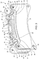
- Figure 10 further shows the radial components of the biasing actions F2, F4, substantially equal to one another and directed in radially inner direction RI.
- the disc-outlet-side biasing action F6 becomes dominating on the disc-inlet-side biasing action F5 to contrast the braking acceleration action 62 of the brake pad 8, 9 with respect to the caliper body 2.
- the tangential component of the disc-outlet-side biasing action F3 balances the sum of the action of the braking acceleration 62 and of the tangential component of the disc-inlet-side biasing action F1 and concurrently the radial component of the disc-outlet-side biasing action F4 balances the sum of the radial component of the disc-inlet-side biasing action F2 and the braking acceleration action 62 applied in the center of gravity of the brake pad 8, 9.
- a disc brake 3 comprising at least one brake caliper 3 according to any one of the embodiments described above, and at least one brake disc 4 having opposite braking surfaces 5, 6.
Landscapes
- Engineering & Computer Science (AREA)
- General Engineering & Computer Science (AREA)
- Mechanical Engineering (AREA)
- Braking Arrangements (AREA)
Claims (9)
- Belag-und-Feder-Anordnung (30) für eine Scheibenbremse (3), umfassend eine Scheibe (4) und einen Bremssattel (1), welcher einen Sattelkörper (2) aufweist, welcher dazu eingerichtet ist, rittlings an der Scheibe (4) angeordnet zu sein, wobei die Scheibenbremse (3) eine axiale Richtung (X-X), welche entweder parallel zu der Rotationsachse der Scheibe (4) ist oder mit dieser zusammenfällt, eine radiale Richtung (R-R) orthogonal zu der axialen Richtung (X-X) und eine Tangential-(T-T) oder Umfangsrichtung (T-T) definiert, welche orthogonal sowohl zu der Axialrichtung (X-X) als auch zu der radialen Richtung (R-R) ist; und wobei ein radial innerer Sinn oder eine radial innere Richtung (RI), welche in eine radiale Richtung (R-R) in Richtung der Rotationsachse der Scheibe (4) gerichtet ist, und entgegengesetzt ein radial äußerer Sinn oder eine radial äußere Richtung (RE) definiert sind; wobei die Belag-und-Feder-Anordnung (30) wenigstens einen Bremsbelag (8, 9) und wenigstens eine Federvorrichtung (10) umfasst, wobei die Federvorrichtung (10) einen Federkörper (11) mit einer vorwiegend longitudinalen Erstreckung aufweist, umfassend:- wenigstens einen Kopplungsabschnitt (12), um die Federvorrichtung (10) mit einem Abschnitt eines zuordenbaren Bremssattels (1) in einer lösbaren Art und Weise zu koppeln;- wenigstens einen ersten Druckabschnitt (13) oder scheibeneinlassseitigen Druckabschnitt (13),- wenigstens einen zweiten Druckabschnitt (14) oder scheibenauslassseitigen Druckabschnitt (14), welcher dem scheibeneinlassseitigen Druckabschnitt (13) in Bezug auf den Kopplungsabschnitt (12) des Druckkörpers (11) longitudinal entgegengesetzt ist;wobei der wenigstens eine erste Druckabschnitt (13) und der wenigstens eine zweite Druckabschnitt (14) dazu eingerichtet sind, wenigstens einen Bremsbelag (8, 9) in Axialrichtung (X-X) weg von der Scheibe (4), in radial innerer Richtung (RI) und in Tangentialrichtung (T-T) der Rotationsrichtung der Scheibe (4) entgegengesetzt vorzuspannen;
wobei jeder des wenigstens einen ersten Druckabschnitts (13) und des wenigstens einen zweiten Druckabschnitts (14) wenigstens eine Aufnahme (17) umfasst, welche eine konvexe Fläche (18) umfasst, welche in einer Arbeitsposition im Wesentlichen zu der radial inneren Richtung (RI) weist und dazu eingerichtet ist, zu dem wenigstens einen Bremsbelag (8, 9) zu weisen; und wobei die konvexe Fläche (18) der wenigstens einen Aufnahme (17) eine Druckfläche (19) umfasst, welche dazu eingerichtet ist, eine axiale, tangentiale und radiale Anlage-Referenz für wenigstens einen Abschnitt einer Halterungsplatte (7) des wenigstens einen Bremsbelags (8, 9) zu bilden, so dass der wenigstens eine Belag (8, 9) durch Drücken gegen die konvexe Fläche (18) der Aufnahme (17) des wenigstens einen ersten Druckabschnitts (13) und des wenigstens einen zweiten Druckabschnitts (14) den Federkörper (11) der Federvorrichtung (10) zwischen dem scheibeneinlassseitigen Druckabschnitt (13) und dem scheibenauslassseitigen Druckabschnitt (14) in Traktion versetzt, wobei eine Anordnung-Vorspannung an die Federvorrichtung (10) bereitgestellt ist; wobei der wenigstens eine Bremsbelag (8, 9) wenigstens ein Reibungsmaterial (31) und wenigstens eine Halterungsplatte (7) umfasst, wobei die wenigstens eine Halterungsplatte (7) eine Reibfläche (32), welcher das Reibungsmaterial (31) zugeordnet ist, eine entgegengesetzte Plattenrückseite (33), welche dazu eingerichtet ist, eine Anlage-Referenz eines Bremssattels (1) zu bilden, welche dem Bremsbelag (8, 9) zugeordnet werden kann, und einen Plattenrand (34) umfasst, welcher die Reibfläche (32) und die entgegengesetzte Plattenrückseite (33) begrenzt;
wobei der Plattenrand (34) einen radial inneren Rand (37), welcher in radial innere Richtung (RI) weist, und einen radial äußeren Rand (38) umfasst, welcher in radial äußere Richtung (RE) weist, wobei der radial äußere Rand (38) wenigstens einen Vorsprung-Rand (41) umfasst, welcher wenigstens einen Vorsprung (39) der Halterungsplatte (7) begrenzt, und wobei der wenigstens eine Vorsprung-Rand (41) wenigstens eine Rampenfläche (40, 50) umfasst, welche in Bezug auf die radiale Richtung (R-R) und die Tangentialrichtung (T-T) geneigt ist;
wobei die wenigstens eine Rampenfläche (40, 50) eine Anlage-Referenz für die wenigstens eine Druckfläche (19) entweder des wenigstens einen scheibeneinlassseitigen Druckabschnitts (13) oder des wenigstens einen scheibenauslassseitigen Druckabschnitts (14) der Federvorrichtung (10) bildet, welche den wenigstens einen Bremsbelag (8, 9) in axialen (X-X). tangentialen (T-T) und radial inneren (RI) Richtungen vorspannt,
dadurch gekennzeichnet, dass
durch Drücken des wenigstens einen Bremsbelags (8, 9) in radial äußere Richtung (RE) gegen die konvexe Fläche (18) der Aufnahme (17) des wenigstens einen Scheibeneinlass-Druckabschnitts (13) und des wenigstens einen scheibenauslassseitigen Druckabschnitts (14) der Federvorrichtung (10) die wenigstens eine Rampenfläche (40, 50) der Halterungsplatte (7) den Federkörper (11) zwischen dem scheibeneinlassseitigen Druckabschnitt (13) und dem scheibenauslassseitigen Druckabschnitt (14) in Traktion versetzt, wobei eine Anordnung-Vorspannung an die Federvorrichtung (10) bereitgestellt ist. - Belag-und-Feder-Anordnung (30) nach Anspruch 1, wobei die konvexe Fläche (18) der Aufnahme (17) des wenigstens einen ersten Druckabschnitts (13) und des wenigstens einen zweiten Druckabschnitts (14) wenigstens einen ersten zylindrischen Flächenabschnitt umfasst, welcher eine in Bezug auf die axiale Richtung (X-X) geneigte Achse aufweist; und wobei die konvexe Fläche (18) der Aufnahme (17) in Richtung der longitudinalen Entwicklungsachse (L-L) des Federkörpers (11) geneigt ist;
und/oder wobei
der Kopplungsabschnitt (12) wenigstens einen Kopplung-Clip umfasst, welcher von dem Federkörper (11) vorspringend vorsteht; und wobei, wenn in Arbeitsposition, sich der wenigstens eine Kopplung-Clip von dem Federkörper (11) in radial äußerer Richtung (RE) erstreckt; und
wobei
der Kopplungsabschnitt (12) wenigstens zwei entgegengesetzte Arme (52, 65) umfasst, welche im Wesentlichen von dem Federkörper (11) vorspringend vorstehen, so dass sie sich nicht-parallel zu der longitudinalen Entwicklungsachse (L-L) des Federkörpers (11) erstrecken; und/oder wobei der wenigstens eine erste Druckabschnitt (13) und der wenigstens eine zweite Druckabschnitt (14) den wenigstens einen Bremsbelags (8, 9) elastisch vorspannen. - Belag-und-Feder-Anordnung (30) nach Anspruch 1 oder 2, wobei
die Federvorrichtung (10) in einem einzigen Stück hergestellt ist; und/oder wobei
die Federvorrichtung (10) in einer Blattfeder hergestellt ist; und/oder wobei die Federvorrichtung (10) durch Abscheren und Falten eines einzigen Metallblechs hergestellt ist. - Belag-und-Feder-Anordnung (30) nach Anspruch 1, wobei die Rampenfläche (40, 50) einen axial inneren Grat (51) umfasst, welcher die Rampenfläche (40, 50) und die Reibfläche (32) des Vorsprungs (39) begrenzt; und wobei
der axial innere Grat (51) der Rampenfläche (40, 50) einen Kontaktabschnitt zwischen dem Bremsbelag (8, 9) und der Druckfläche (19) der Federvorrichtung (10) umfasst; und/oder wobei
ein axial innerer Grat (51) der Rampenfläche (40, 50) im Wesentlichen gradlinig und in Bezug auf die Tangentialrichtung (T-T) und die radiale Richtung (R-R) geneigt ist; und wobei
die wenigstens eine Rampenfläche (40, 50) so geneigt ist, dass eine Erstreckung davon, in einem Abschnitt radial außerhalb des radial äußeren Abschnitts (38) der Halterungsplatte (7), auf eine definierbare Mittelachse (MM) des Bremsbelags (8, 9) trifft, wobei die Mittelachse (M-M) parallel zu der radialen Richtung (R-R) ist; und/oder wobei
der wenigstens eine erste Druckabschnitt (19) des wenigstens entweder ersten Druckabschnitts (13) oder des wenigstens einen zweiten Druckabschnitts (14) der Federvorrichtung (10) den wenigstens einen Bremsbelag (8, 9) elastisch vorspannt. - Belag-und-Feder-Anordnung (30) nach Anspruch 1 oder 4,
wobei der radial äußere Rand (38) der Halterungsplatte (7) zwei separate Vorsprünge (39) in Bezug auf die Mittelachse (M-M) tangential entgegengesetzt umfasst, wobei jeder der beiden separaten Vorsprünge eine Rampenfläche (40, 50) umfasst, so dass der radial äußere Rand (38) der Halterungsplatte (7) zwei entgegengesetzte Rampenflächen (40, 50) umfasst; und/oder wobei
die beiden entgegengesetzten Rampenflächen (40, 50) eine erste Rampenfläche (40) oder scheibeneinlassseitige Rampenfläche (40) und eine zweite entgegengesetzte Rampenfläche (50) oder scheibenauslassseitige Rampenfläche (50) umfassen;
und wobei
die scheibeneinlassseitige Rampenfläche (40) eine Anlage-Referenz für die wenigstens eine Druckfläche (19) des scheibeneinlassseitigen Druckabschnitts (13) der Federvorrichtung (10) bildet und die scheibenauslassseitige Rampenfläche (50) eine Anlage-Referenz für die wenigstens eine Druckfläche (19) des scheibenauslassseitigen Druckabschnitts (14) der Federvorrichtung (10) bildet; und/oder wobei die Erstreckungen der beiden entgegengesetzten seitigen Rampen (40, 50) in einem Abschnitt radial außerhalb des radial äußeren Rands (38) der Halterungsplatte (7) konvergieren, und/oder wobei
der radial äußere Rand (38) der Halterungsplatte (7) einen radial äußeren Mittelrandabschnitt (42) und entgegengesetzt radial äußere Seitenrandabschnitte (43) tangential an der Seite des radial äußeren Mittelrandabschnitts (42) umfasst, wobei wenigstens einer der radial äußeren Seitenrandabschnitte (43) die Rampenfläche (40, 50) umfasst; und/oder wobei
der radial äußere Mittelrandabschnitt (42) frei von Fortsätzen oder Vorsprüngen ist; und/oder wobei
die Belag-und-Feder-Anordnung (30) zwei entgegengesetzte Bremsbeläge (8, 9) und eine Federvorrichtung (10) umfasst, welche an den tangentialen und axialen Enden des Federkörpers (11) vier Aufnahmen (17) umfasst, wobei jede Aufnahme (17) die wenigstens eine Druckfläche (19) umfasst, um die beiden entgegengesetzten Bremsbeläge (8, 9) gleichzeitig sowohl in axialer Richtung (X-X) von der Scheibe (4) weg als auch in radial innere Richtung (RI) und in Tangentialrichtung (T-T) zu beeinflussen, um der Tangentialbeschleunigung des Bremsbelags (8, 9) während der Bremswirkung entgegenzuwirken. - Bremssattel (1) für eine Scheibenbremse (3), wobei die Scheibenbremse (3) eine axiale Richtung (X-X), welche entweder parallel zu der Rotationsachse (4) der Bremsscheibe (3) ist oder mit dieser zusammenfällt, eine radiale Richtung (R-R) orthogonal zu der axialen Richtung (X-X) und eine Tangential-(T-T) oder Umfangsrichtung (T-T) definiert, welche orthogonal sowohl zu der Axialrichtung (X-X) als auch zu der radialen Richtung (R-R) ist; und wobei ein radial innerer Sinn oder eine radial innere Richtung (RI), welche in eine radiale Richtung (R-R) in Richtung der Rotationsachse der Scheibe (4) gerichtet ist, und entgegengesetzt ein radial äußerer Sinn oder eine radiale äußere Richtung (RE) definiert sind;
wobei der Bremssattel (1) einen Sattelkörper (2), welcher dazu eingerichtet ist, rittlings der Scheibe (4) angeordnet zu sein, und wenigstens eine Belag-und-Feder-Anordnung (30) nach einem der Ansprüche 1 bis 4 oder 5 umfasst;
wobei der Sattelkörper (2) umfasst:- zwei entgegengesetzte längliche Elemente (55, 56), von welchen jedes dazu eingerichtet ist, entweder direkt oder indirekt mittels des wenigstens einen Bremsbelags (8, 9) zu einer Bremsfläche (5, 6) der Scheibe (4) zu weisen,- wenigstens eine Sattelbrücke (20, 57), welche die beiden länglichen Elemente (55, 56) miteinander verbindet;und wobei die Federvorrichtung (10) durch Einrasten mittels ihres Kopplungsabschnitts (12) mit der Sattelbrücke (20, 57) gekoppelt ist und wenigstens einen Bremsbelag (8, 9) in axialer Richtung (X-X) von der Scheibe (4) weg, in radial innerer Richtung (RI) und in Tangentialrichtung (T-T) dem Rotationsinn der Scheibe (4) entgegengesetzt vorspannt, um der Tangentialbeschleunigung des Bremsbelags (8, 9) während der Bremswirkung entgegenzuwirken;
und wobei, während der Bremswirkung, der wenigstens eine Bremsbelag (8, 9) den Federkörper (11) der Federvorrichtung (10) zwischen dem Kopplungsabschnitt (12) und wenigstens entweder dem scheibeneinlassseitigen Druckabschnitt (13) oder dem scheibenauslassseitigen Druckabschnitt (14) einer Traktionsreaktion aussetzt. - Bremssattel (1) nach Anspruch 6, wobei die Sattelbrücke (20, 57) eine mittige Sattelbrücke (20) ist, so dass die Federvorrichtung (10) durch Einrasten mittels ihres Kopplungsabschnitts (12) mit der mittigen Sattelbrücke (20) gekoppelt wird; und wobei die mittige Sattelbrücke (20) eine radial innere Brückenseite (58) umfasst, welche dazu eingerichtet ist, zu der Scheibe (4) der Bremsscheibe (3) zu weisen, und der Kopplungsabschnitt (12) der Federvorrichtung (10) wenigstens einen radial inneren Brückenseitenabschnitt (58) der mittigen Sattelbrücke (20) umfasst; und wobei
der Kopplungsabschnitt (12) der Federvorrichtung (10) einen scheibeneinlassseitigen Kopplungsarm (52) und einen entgegengesetzten Scheibenauslass-Kopplungsarm (65) umfasst, so dass, während der Bremswirkung, der wenigstens eine Bremsbelag (8, 9) den Federkörper (11) der Federvorrichtung (10) zwischen dem Scheibeneinlass-Druckabschnitt (13) und dem scheibenauslassseitigen Kopplungsarm (65) und zwischen dem scheibenauslassseitigen Druckabschnitt (14) und dem scheibeneinlassseitigen Kopplungsarm (52) in Traktion versetzt. - Bremssattel (1) nach Anspruch 6 oder 7, wobei jedes der wenigstens zwei entgegengesetzten länglichen Elemente (55, 56) ein inneres sattelseitiges längliches Element umfasst, welches dazu eingerichtet ist, entweder direkt oder indirekt mittels des wenigstens einen Bremsbelags (8, 9) zu einer Bremsfläche (5, 6) der Scheibe (4) zu weisen; wobei das innere sattelseitige längliche Element (64) des Sattelkörpers (2) Taschenwände (66, 67) umfasst, welche wenigstens teilweise eine Belag-Aufnahmetasche begrenzen, wobei die Taschenwände (66, 67) eine tangentiale Anlage-Referenz für die scheibeneinlassseitige Flanke (35) und die scheibenauslassseitige Flanke (36) der Halterungsplatte (7) des wenigstens einen Bremsbelags (8, 9) bilden, um die Bremswirkung des wenigstens einen Bremsbelags (8, 9) auf den Sattelkörper (2) des Bremssattels (1) zu übertragen; und/oder wobei
der Sattelkörper (2) von dem Monoblock-Typ ist; oder wobei
der Sattelkörper (2) zwei Sattel-Halbkörper (59) umfasst. - Scheibenbremse (3), umfassend wenigstens einen Bremssattel (1) nach einem der Ansprüche 6 bis 8 und wenigstens eine Scheibe (4), welche entgegengesetzte Bremsflächen (5, 6) umfasst.
Applications Claiming Priority (2)
| Application Number | Priority Date | Filing Date | Title |
|---|---|---|---|
| IT102016000130800A IT201600130800A1 (it) | 2016-12-23 | 2016-12-23 | Dispositivo a molla per freno a disco, assieme di pastiglia e molla e pinza freno |
| PCT/IB2017/057924 WO2018116088A1 (en) | 2016-12-23 | 2017-12-14 | Spring device for disc brake, pad spring and disc brake assembly |
Publications (2)
| Publication Number | Publication Date |
|---|---|
| EP3559495A1 EP3559495A1 (de) | 2019-10-30 |
| EP3559495B1 true EP3559495B1 (de) | 2020-10-21 |
Family
ID=58670214
Family Applications (1)
| Application Number | Title | Priority Date | Filing Date |
|---|---|---|---|
| EP17826566.6A Active EP3559495B1 (de) | 2016-12-23 | 2017-12-14 | Federvorrichtung für scheibenbremse, auflagefeder und scheibenbremsanordnung |
Country Status (5)
| Country | Link |
|---|---|
| US (1) | US11401990B2 (de) |
| EP (1) | EP3559495B1 (de) |
| CN (1) | CN110121607B (de) |
| IT (1) | IT201600130800A1 (de) |
| WO (1) | WO2018116088A1 (de) |
Cited By (1)
| Publication number | Priority date | Publication date | Assignee | Title |
|---|---|---|---|---|
| US12287018B2 (en) | 2021-09-08 | 2025-04-29 | Brembo S.P.A. | Brake pad, brake caliper assembly, disc brake |
Families Citing this family (14)
| Publication number | Priority date | Publication date | Assignee | Title |
|---|---|---|---|---|
| WO2020125954A1 (en) * | 2018-12-18 | 2020-06-25 | Volvo Truck Corporation | Wheel brake arrangement |
| CN113195920B (zh) * | 2018-12-20 | 2023-08-11 | 乐姆宝公开有限公司 | 至少两个制动衬垫和至少一个弹簧的组件 |
| IT201800020251A1 (it) * | 2018-12-20 | 2020-06-20 | Freni Brembo Spa | Corpo pinza e pinza freno con detto corpo |
| IT201800020401A1 (it) * | 2018-12-20 | 2020-06-20 | Freni Brembo Spa | Molla ritorno pastiglie per un corpo pinza di freno a disco |
| KR102749391B1 (ko) * | 2019-12-06 | 2025-01-02 | 현대모비스 주식회사 | 캘리퍼 브레이크용 패드 스프링 |
| CN115087815B (zh) * | 2020-02-12 | 2023-12-22 | 日立安斯泰莫株式会社 | 车辆用盘式制动器 |
| KR102792005B1 (ko) * | 2020-02-19 | 2025-04-08 | 현대모비스 주식회사 | 차량용 브레이크 장치 |
| USD947733S1 (en) * | 2020-03-13 | 2022-04-05 | Mann+Hummel Gmbh | Brake dust filter |
| KR102878772B1 (ko) * | 2020-08-25 | 2025-10-31 | 현대모비스 주식회사 | 브레이크 장치용 패드 라이너 |
| IT202100023168A1 (it) * | 2021-09-08 | 2023-03-08 | Brembo Spa | Pastiglia freno; assieme di pastiglia; assieme di pinza freno |
| IT202100025361A1 (it) * | 2021-10-04 | 2023-04-04 | Brembo Spa | Molla, assieme di molla e pastiglia freno, assieme di corpo pinza |
| DE112023002912T5 (de) * | 2022-07-01 | 2025-05-08 | Brembo S.P.A. | Bandfeder- und Bremsbelagsanordnung, Bremssattel, Bremsbelag |
| CN117231647A (zh) * | 2023-10-24 | 2023-12-15 | 安徽江淮汽车集团股份有限公司 | 一种高性能可拆卸的复合式卡钳摩擦片整体结构 |
| IT202300023289A1 (it) * | 2023-11-06 | 2025-05-06 | Brembo Spa | Pinza freno |
Family Cites Families (21)
| Publication number | Priority date | Publication date | Assignee | Title |
|---|---|---|---|---|
| DE3709396A1 (de) * | 1987-03-21 | 1988-09-29 | Teves Gmbh Alfred | Scheibenbremse, insbesondere fuer kraftfahrzeuge |
| EP0703378B1 (de) * | 1994-09-22 | 2001-12-05 | Meritor Heavy Vehicle Technology, LLC | Scheibenbremsbelag und Haltesystem |
| DE4442796A1 (de) | 1994-12-01 | 1996-06-05 | Teves Gmbh Alfred | Niederhaltefeder f}r Scheibenbremsen |
| JPH09329164A (ja) | 1996-04-08 | 1997-12-22 | Aisin Seiki Co Ltd | ディスクブレーキ |
| GB0301799D0 (en) * | 2003-01-25 | 2003-02-26 | Meritor Heavy Vehicle Braking | Disc brake pad hold down spring and backplate |
| JP4656027B2 (ja) * | 2006-09-08 | 2011-03-23 | 株式会社アドヴィックス | ディスクブレーキ |
| CN101563550B (zh) * | 2006-12-18 | 2012-11-07 | 福乐尼·乐姆宝公开有限公司 | 带有冷却系统的制动卡钳 |
| DE102007046945B4 (de) * | 2007-10-01 | 2009-07-16 | Knorr-Bremse Systeme für Nutzfahrzeuge GmbH | Bremsbelaghalterung und Bremsbelag einer Scheibenbremse |
| JP5540387B2 (ja) | 2008-12-24 | 2014-07-02 | フレニ ブレンボ エス.ピー.エー. | ディスクブレーキキャリパ用のワイヤースプリング及びディスクブレーキキャリパ |
| DE102010043898A1 (de) * | 2010-06-02 | 2011-12-08 | Continental Teves Ag & Co. Ohg | Festsattelbremse und Bremsbelag für eine Festsattelbremse |
| CN102954129A (zh) * | 2011-08-26 | 2013-03-06 | 常州市武进骏宇汽配涂料有限公司 | 盘式刹车片 |
| ITMI20111693A1 (it) * | 2011-09-20 | 2013-03-21 | Freni Brembo Spa | Corpo pinza per freno a disco |
| DE102012023813A1 (de) * | 2012-12-05 | 2014-06-05 | Wabco Radbremsen Gmbh | Scheibenbremse, insbesondere für Nutzfahrzeuge, sowie Niederhaltefeder einer solchen Scheibenbremse |
| JP6219576B2 (ja) * | 2013-03-06 | 2017-10-25 | 日立オートモティブシステムズ株式会社 | ディスクブレーキ |
| JP6155056B2 (ja) * | 2013-03-06 | 2017-06-28 | 日立オートモティブシステムズ株式会社 | ディスクブレーキ |
| DE102013008161A1 (de) * | 2013-05-13 | 2014-11-13 | Wabco Europe Bvba | Sattelscheibenbremse eines Fahrzeugs, insbesondere eines Nutzfahrzeuges, und Bremssattel einer solchen Bremse |
| JP6261289B2 (ja) * | 2013-11-07 | 2018-01-17 | 曙ブレーキ工業株式会社 | ディスクブレーキ用パッドスプリング |
| US10316912B2 (en) * | 2014-04-08 | 2019-06-11 | Freni Brembo S.P.A. | Disc brake pad, spring for disc brake caliper and disk brake caliper assembly |
| CN106536961B (zh) * | 2014-05-27 | 2019-01-29 | 福乐尼·乐姆宝公开有限公司 | 盘式制动器的卡钳的弹簧 |
| US9726243B2 (en) * | 2015-03-20 | 2017-08-08 | Bendix Spicer Foundation Brake Llc | Disc brake pad retention system and mounting method |
| JP6686852B2 (ja) * | 2016-11-18 | 2020-04-22 | 株式会社アドヴィックス | ピストン対向型のディスクブレーキ |
-
2016
- 2016-12-23 IT IT102016000130800A patent/IT201600130800A1/it unknown
-
2017
- 2017-12-14 US US16/473,122 patent/US11401990B2/en active Active
- 2017-12-14 WO PCT/IB2017/057924 patent/WO2018116088A1/en not_active Ceased
- 2017-12-14 EP EP17826566.6A patent/EP3559495B1/de active Active
- 2017-12-14 CN CN201780080137.4A patent/CN110121607B/zh active Active
Non-Patent Citations (1)
| Title |
|---|
| None * |
Cited By (1)
| Publication number | Priority date | Publication date | Assignee | Title |
|---|---|---|---|---|
| US12287018B2 (en) | 2021-09-08 | 2025-04-29 | Brembo S.P.A. | Brake pad, brake caliper assembly, disc brake |
Also Published As
| Publication number | Publication date |
|---|---|
| US11401990B2 (en) | 2022-08-02 |
| WO2018116088A1 (en) | 2018-06-28 |
| US20210356006A1 (en) | 2021-11-18 |
| IT201600130800A1 (it) | 2018-06-23 |
| EP3559495A1 (de) | 2019-10-30 |
| CN110121607B (zh) | 2021-06-01 |
| CN110121607A (zh) | 2019-08-13 |
Similar Documents
| Publication | Publication Date | Title |
|---|---|---|
| US11401990B2 (en) | Spring device for disc brake, pad spring and disc brake assembly | |
| US5464077A (en) | Floating-caliper spot-type disc brake for high-powered vehicles | |
| US5363944A (en) | Floating-frame spot-type disc brake for high-torque automotive vehicles | |
| US11773932B2 (en) | Pad return spring for a disc brake caliper body | |
| US10844917B2 (en) | Brake caliper | |
| US4408681A (en) | Disc brake | |
| US7458447B2 (en) | Disc brake assembly | |
| EP3809009B1 (de) | Fahrzeugscheibenbremse | |
| US10240649B2 (en) | Caliper for disc brake | |
| US7810617B2 (en) | Friction element and disc brake | |
| JP2020034043A (ja) | ディスクブレーキ | |
| CN110945261B (zh) | 车辆用盘式制动器 | |
| JPH11108089A (ja) | ディスクブレーキ | |
| CN110730876A (zh) | 盘式制动器 | |
| US4360081A (en) | Disc brake | |
| JP5759793B2 (ja) | ディスクブレーキ | |
| JP2003148525A (ja) | ディスクブレーキ | |
| WO2010137715A1 (ja) | 車両用ディスクブレーキ | |
| JP6149273B2 (ja) | ディスクブレーキ | |
| JP2006097867A (ja) | ディスクブレーキ | |
| JPS5838655B2 (ja) | ノリモノヨウエンバンブレ−キ | |
| JP2018123836A (ja) | ディスクブレーキ用パッド及びディスクブレーキ装置 | |
| JP4288197B2 (ja) | 車両用ディスクブレーキ | |
| JPH0716119Y2 (ja) | ディスクブレーキ | |
| JP2015197143A (ja) | ディスクブレーキ |
Legal Events
| Date | Code | Title | Description |
|---|---|---|---|
| STAA | Information on the status of an ep patent application or granted ep patent |
Free format text: STATUS: UNKNOWN |
|
| STAA | Information on the status of an ep patent application or granted ep patent |
Free format text: STATUS: THE INTERNATIONAL PUBLICATION HAS BEEN MADE |
|
| PUAI | Public reference made under article 153(3) epc to a published international application that has entered the european phase |
Free format text: ORIGINAL CODE: 0009012 |
|
| STAA | Information on the status of an ep patent application or granted ep patent |
Free format text: STATUS: REQUEST FOR EXAMINATION WAS MADE |
|
| 17P | Request for examination filed |
Effective date: 20190613 |
|
| AK | Designated contracting states |
Kind code of ref document: A1 Designated state(s): AL AT BE BG CH CY CZ DE DK EE ES FI FR GB GR HR HU IE IS IT LI LT LU LV MC MK MT NL NO PL PT RO RS SE SI SK SM TR |
|
| AX | Request for extension of the european patent |
Extension state: BA ME |
|
| DAV | Request for validation of the european patent (deleted) | ||
| DAX | Request for extension of the european patent (deleted) | ||
| GRAP | Despatch of communication of intention to grant a patent |
Free format text: ORIGINAL CODE: EPIDOSNIGR1 |
|
| STAA | Information on the status of an ep patent application or granted ep patent |
Free format text: STATUS: GRANT OF PATENT IS INTENDED |
|
| INTG | Intention to grant announced |
Effective date: 20200618 |
|
| GRAS | Grant fee paid |
Free format text: ORIGINAL CODE: EPIDOSNIGR3 |
|
| GRAA | (expected) grant |
Free format text: ORIGINAL CODE: 0009210 |
|
| STAA | Information on the status of an ep patent application or granted ep patent |
Free format text: STATUS: THE PATENT HAS BEEN GRANTED |
|
| AK | Designated contracting states |
Kind code of ref document: B1 Designated state(s): AL AT BE BG CH CY CZ DE DK EE ES FI FR GB GR HR HU IE IS IT LI LT LU LV MC MK MT NL NO PL PT RO RS SE SI SK SM TR |
|
| REG | Reference to a national code |
Ref country code: GB Ref legal event code: FG4D |
|
| REG | Reference to a national code |
Ref country code: CH Ref legal event code: EP |
|
| REG | Reference to a national code |
Ref country code: DE Ref legal event code: R096 Ref document number: 602017026082 Country of ref document: DE |
|
| REG | Reference to a national code |
Ref country code: IE Ref legal event code: FG4D |
|
| REG | Reference to a national code |
Ref country code: AT Ref legal event code: REF Ref document number: 1326135 Country of ref document: AT Kind code of ref document: T Effective date: 20201115 |
|
| REG | Reference to a national code |
Ref country code: AT Ref legal event code: MK05 Ref document number: 1326135 Country of ref document: AT Kind code of ref document: T Effective date: 20201021 |
|
| REG | Reference to a national code |
Ref country code: NL Ref legal event code: MP Effective date: 20201021 |
|
| PG25 | Lapsed in a contracting state [announced via postgrant information from national office to epo] |
Ref country code: FI Free format text: LAPSE BECAUSE OF FAILURE TO SUBMIT A TRANSLATION OF THE DESCRIPTION OR TO PAY THE FEE WITHIN THE PRESCRIBED TIME-LIMIT Effective date: 20201021 Ref country code: PT Free format text: LAPSE BECAUSE OF FAILURE TO SUBMIT A TRANSLATION OF THE DESCRIPTION OR TO PAY THE FEE WITHIN THE PRESCRIBED TIME-LIMIT Effective date: 20210222 Ref country code: RS Free format text: LAPSE BECAUSE OF FAILURE TO SUBMIT A TRANSLATION OF THE DESCRIPTION OR TO PAY THE FEE WITHIN THE PRESCRIBED TIME-LIMIT Effective date: 20201021 Ref country code: GR Free format text: LAPSE BECAUSE OF FAILURE TO SUBMIT A TRANSLATION OF THE DESCRIPTION OR TO PAY THE FEE WITHIN THE PRESCRIBED TIME-LIMIT Effective date: 20210122 Ref country code: NO Free format text: LAPSE BECAUSE OF FAILURE TO SUBMIT A TRANSLATION OF THE DESCRIPTION OR TO PAY THE FEE WITHIN THE PRESCRIBED TIME-LIMIT Effective date: 20210121 |
|
| REG | Reference to a national code |
Ref country code: LT Ref legal event code: MG4D |
|
| PG25 | Lapsed in a contracting state [announced via postgrant information from national office to epo] |
Ref country code: ES Free format text: LAPSE BECAUSE OF FAILURE TO SUBMIT A TRANSLATION OF THE DESCRIPTION OR TO PAY THE FEE WITHIN THE PRESCRIBED TIME-LIMIT Effective date: 20201021 Ref country code: AT Free format text: LAPSE BECAUSE OF FAILURE TO SUBMIT A TRANSLATION OF THE DESCRIPTION OR TO PAY THE FEE WITHIN THE PRESCRIBED TIME-LIMIT Effective date: 20201021 Ref country code: SE Free format text: LAPSE BECAUSE OF FAILURE TO SUBMIT A TRANSLATION OF THE DESCRIPTION OR TO PAY THE FEE WITHIN THE PRESCRIBED TIME-LIMIT Effective date: 20201021 Ref country code: PL Free format text: LAPSE BECAUSE OF FAILURE TO SUBMIT A TRANSLATION OF THE DESCRIPTION OR TO PAY THE FEE WITHIN THE PRESCRIBED TIME-LIMIT Effective date: 20201021 Ref country code: IS Free format text: LAPSE BECAUSE OF FAILURE TO SUBMIT A TRANSLATION OF THE DESCRIPTION OR TO PAY THE FEE WITHIN THE PRESCRIBED TIME-LIMIT Effective date: 20210221 Ref country code: LV Free format text: LAPSE BECAUSE OF FAILURE TO SUBMIT A TRANSLATION OF THE DESCRIPTION OR TO PAY THE FEE WITHIN THE PRESCRIBED TIME-LIMIT Effective date: 20201021 Ref country code: BG Free format text: LAPSE BECAUSE OF FAILURE TO SUBMIT A TRANSLATION OF THE DESCRIPTION OR TO PAY THE FEE WITHIN THE PRESCRIBED TIME-LIMIT Effective date: 20210121 |
|
| PG25 | Lapsed in a contracting state [announced via postgrant information from national office to epo] |
Ref country code: NL Free format text: LAPSE BECAUSE OF FAILURE TO SUBMIT A TRANSLATION OF THE DESCRIPTION OR TO PAY THE FEE WITHIN THE PRESCRIBED TIME-LIMIT Effective date: 20201021 Ref country code: HR Free format text: LAPSE BECAUSE OF FAILURE TO SUBMIT A TRANSLATION OF THE DESCRIPTION OR TO PAY THE FEE WITHIN THE PRESCRIBED TIME-LIMIT Effective date: 20201021 |
|
| REG | Reference to a national code |
Ref country code: CH Ref legal event code: PK Free format text: BERICHTIGUNGEN |
|
| RAP4 | Party data changed (patent owner data changed or rights of a patent transferred) |
Owner name: BREMBO S.P.A. |
|
| RIN2 | Information on inventor provided after grant (corrected) |
Inventor name: LONGHI, DANIEL Inventor name: COSTA, MATTEO Inventor name: D'ALESSIO, DAVIDE |
|
| REG | Reference to a national code |
Ref country code: DE Ref legal event code: R097 Ref document number: 602017026082 Country of ref document: DE |
|
| PG25 | Lapsed in a contracting state [announced via postgrant information from national office to epo] |
Ref country code: RO Free format text: LAPSE BECAUSE OF FAILURE TO SUBMIT A TRANSLATION OF THE DESCRIPTION OR TO PAY THE FEE WITHIN THE PRESCRIBED TIME-LIMIT Effective date: 20201021 Ref country code: SK Free format text: LAPSE BECAUSE OF FAILURE TO SUBMIT A TRANSLATION OF THE DESCRIPTION OR TO PAY THE FEE WITHIN THE PRESCRIBED TIME-LIMIT Effective date: 20201021 Ref country code: SM Free format text: LAPSE BECAUSE OF FAILURE TO SUBMIT A TRANSLATION OF THE DESCRIPTION OR TO PAY THE FEE WITHIN THE PRESCRIBED TIME-LIMIT Effective date: 20201021 Ref country code: LT Free format text: LAPSE BECAUSE OF FAILURE TO SUBMIT A TRANSLATION OF THE DESCRIPTION OR TO PAY THE FEE WITHIN THE PRESCRIBED TIME-LIMIT Effective date: 20201021 Ref country code: CZ Free format text: LAPSE BECAUSE OF FAILURE TO SUBMIT A TRANSLATION OF THE DESCRIPTION OR TO PAY THE FEE WITHIN THE PRESCRIBED TIME-LIMIT Effective date: 20201021 Ref country code: EE Free format text: LAPSE BECAUSE OF FAILURE TO SUBMIT A TRANSLATION OF THE DESCRIPTION OR TO PAY THE FEE WITHIN THE PRESCRIBED TIME-LIMIT Effective date: 20201021 |
|
| REG | Reference to a national code |
Ref country code: CH Ref legal event code: PL |
|
| PLBE | No opposition filed within time limit |
Free format text: ORIGINAL CODE: 0009261 |
|
| STAA | Information on the status of an ep patent application or granted ep patent |
Free format text: STATUS: NO OPPOSITION FILED WITHIN TIME LIMIT |
|
| PG25 | Lapsed in a contracting state [announced via postgrant information from national office to epo] |
Ref country code: DK Free format text: LAPSE BECAUSE OF FAILURE TO SUBMIT A TRANSLATION OF THE DESCRIPTION OR TO PAY THE FEE WITHIN THE PRESCRIBED TIME-LIMIT Effective date: 20201021 Ref country code: MC Free format text: LAPSE BECAUSE OF FAILURE TO SUBMIT A TRANSLATION OF THE DESCRIPTION OR TO PAY THE FEE WITHIN THE PRESCRIBED TIME-LIMIT Effective date: 20201021 |
|
| RAP4 | Party data changed (patent owner data changed or rights of a patent transferred) |
Owner name: BREMBO S.P.A. |
|
| REG | Reference to a national code |
Ref country code: BE Ref legal event code: MM Effective date: 20201231 |
|
| 26N | No opposition filed |
Effective date: 20210722 |
|
| PG25 | Lapsed in a contracting state [announced via postgrant information from national office to epo] |
Ref country code: IE Free format text: LAPSE BECAUSE OF NON-PAYMENT OF DUE FEES Effective date: 20201214 Ref country code: FR Free format text: LAPSE BECAUSE OF NON-PAYMENT OF DUE FEES Effective date: 20201221 Ref country code: AL Free format text: LAPSE BECAUSE OF FAILURE TO SUBMIT A TRANSLATION OF THE DESCRIPTION OR TO PAY THE FEE WITHIN THE PRESCRIBED TIME-LIMIT Effective date: 20201021 Ref country code: LU Free format text: LAPSE BECAUSE OF NON-PAYMENT OF DUE FEES Effective date: 20201214 |
|
| PG25 | Lapsed in a contracting state [announced via postgrant information from national office to epo] |
Ref country code: LI Free format text: LAPSE BECAUSE OF NON-PAYMENT OF DUE FEES Effective date: 20201231 Ref country code: CH Free format text: LAPSE BECAUSE OF NON-PAYMENT OF DUE FEES Effective date: 20201231 Ref country code: SI Free format text: LAPSE BECAUSE OF FAILURE TO SUBMIT A TRANSLATION OF THE DESCRIPTION OR TO PAY THE FEE WITHIN THE PRESCRIBED TIME-LIMIT Effective date: 20201021 |
|
| PG25 | Lapsed in a contracting state [announced via postgrant information from national office to epo] |
Ref country code: IS Free format text: LAPSE BECAUSE OF FAILURE TO SUBMIT A TRANSLATION OF THE DESCRIPTION OR TO PAY THE FEE WITHIN THE PRESCRIBED TIME-LIMIT Effective date: 20210221 Ref country code: TR Free format text: LAPSE BECAUSE OF FAILURE TO SUBMIT A TRANSLATION OF THE DESCRIPTION OR TO PAY THE FEE WITHIN THE PRESCRIBED TIME-LIMIT Effective date: 20201021 Ref country code: MT Free format text: LAPSE BECAUSE OF FAILURE TO SUBMIT A TRANSLATION OF THE DESCRIPTION OR TO PAY THE FEE WITHIN THE PRESCRIBED TIME-LIMIT Effective date: 20201021 Ref country code: CY Free format text: LAPSE BECAUSE OF FAILURE TO SUBMIT A TRANSLATION OF THE DESCRIPTION OR TO PAY THE FEE WITHIN THE PRESCRIBED TIME-LIMIT Effective date: 20201021 |
|
| PG25 | Lapsed in a contracting state [announced via postgrant information from national office to epo] |
Ref country code: MK Free format text: LAPSE BECAUSE OF FAILURE TO SUBMIT A TRANSLATION OF THE DESCRIPTION OR TO PAY THE FEE WITHIN THE PRESCRIBED TIME-LIMIT Effective date: 20201021 |
|
| PG25 | Lapsed in a contracting state [announced via postgrant information from national office to epo] |
Ref country code: BE Free format text: LAPSE BECAUSE OF NON-PAYMENT OF DUE FEES Effective date: 20201231 |
|
| REG | Reference to a national code |
Ref country code: DE Ref legal event code: R081 Ref document number: 602017026082 Country of ref document: DE Owner name: BREMBO S.P.A., CURNO, IT Free format text: FORMER OWNER: FRENI BREMBO S.P.A., CURNO, BERGAMO, IT |
|
| P01 | Opt-out of the competence of the unified patent court (upc) registered |
Effective date: 20230526 |
|
| PGFP | Annual fee paid to national office [announced via postgrant information from national office to epo] |
Ref country code: GB Payment date: 20251219 Year of fee payment: 9 |
|
| PGFP | Annual fee paid to national office [announced via postgrant information from national office to epo] |
Ref country code: IT Payment date: 20251007 Year of fee payment: 9 |
|
| PGFP | Annual fee paid to national office [announced via postgrant information from national office to epo] |
Ref country code: DE Payment date: 20251222 Year of fee payment: 9 |