EP3556499B1 - Fraiseuse destinée à l'usinage de matériaux plastiques - Google Patents
Fraiseuse destinée à l'usinage de matériaux plastiques Download PDFInfo
- Publication number
- EP3556499B1 EP3556499B1 EP18167631.3A EP18167631A EP3556499B1 EP 3556499 B1 EP3556499 B1 EP 3556499B1 EP 18167631 A EP18167631 A EP 18167631A EP 3556499 B1 EP3556499 B1 EP 3556499B1
- Authority
- EP
- European Patent Office
- Prior art keywords
- insert holder
- base body
- milling cutter
- clamping
- Prior art date
- Legal status (The legal status is an assumption and is not a legal conclusion. Google has not performed a legal analysis and makes no representation as to the accuracy of the status listed.)
- Active
Links
Images


Classifications
-
- B—PERFORMING OPERATIONS; TRANSPORTING
- B23—MACHINE TOOLS; METAL-WORKING NOT OTHERWISE PROVIDED FOR
- B23C—MILLING
- B23C5/00—Milling-cutters
- B23C5/16—Milling-cutters characterised by physical features other than shape
- B23C5/20—Milling-cutters characterised by physical features other than shape with removable cutter bits or teeth or cutting inserts
- B23C5/22—Securing arrangements for bits or teeth or cutting inserts
- B23C5/24—Securing arrangements for bits or teeth or cutting inserts adjustable
- B23C5/2462—Securing arrangements for bits or teeth or cutting inserts adjustable the adjusting means being oblique surfaces
Definitions
- the invention relates to a milling cutter for processing plastic materials, comprising a disk-shaped base body which can be fixed to a milling spindle, with milling tools designed as cutting pins projecting beyond the plane of the base body being embedded in the region of the periphery of the disk-shaped base body, which are clamped in insert holders and wherein the individual insert holder is fixed in a receiving pocket in the base body.
- Milling cutters of this type which are known from the prior art, are particularly suitable for processing transparent plastics.
- the milling cutter consists primarily of a base body which is designed as a disk, with an opening being present in the center of the disk, in which the milling spindle is fixed in order to set the disk in rotation.
- Pen-like milling tools which are set with diamonds as the cutting material, are embedded in this disc, in particular on the periphery of the disc.
- two, three or four milling tools lying opposite one another are arranged in the base body, with some being designed as rough cutters and others as finishing cutters. In this way, surfaces on a transparent plastic block that are milled and polished can be processed.
- the milling tools consisting of the holder and the cutting pin itself are let into pockets in the base body, which are designed as bores, and are braced therein by means of clamping bolts.
- a cutter head with roughing and finishing cutting edges which comprises a base body, which can be attached to a milling spindle.
- milling tools that protrude beyond the plane of the base body are also embedded in the periphery of the base body.
- the insert holders themselves are used in circular pockets in the base body, with the insert holder and thus the milling tool being able to be aligned or fixed in the base body by means of a positioning pin.
- Another milling cutter for processing is from the GB 11 60 425 A known, this cutting tool also has a base body which shows recessed milling tools in the region of a periphery.
- the insert holder and thus the milling tool are aligned and fixed in the base body by means of a positioning pin.
- the milling cutter as such also includes a disk-shaped base body that can be fixed to a milling spindle, with milling tools designed as cutting pins projecting beyond the plane of the base body being embedded in the region of the periphery of the disk-shaped base body, which are clamped in insert holders.
- U.S. Patent 5,054,972 discloses a rotary mandrel tool for use in a portable drill.
- the tool is designed to sharpen the ends of metal pins and particularly snowmobile tread pins or spikes.
- the tool has a cylindrical head with a tapered central opening axially aligned with the axis of rotation of the head. Radial grooves extend through the wall of the head from the central opening to the outer surface thereof. One wall of each groove forms a stop wall against which a preferably triangular cutting blade with a thickness substantially less than the width of the groove.
- the cutting blade is frictionally held against the stop wall by a set screw extending from the opposite wall against the cutting blade, leaving an opening extending along the groove beyond the cutting tool and wide enough to permit exit from the central To create an opening for chips to be cut out of the end of the spigot by the cutting edges of the cutting tool.
- the individual insert holder is fixed in a receiving pocket in the base body by means of a positioning pin.
- the positioning pins are divided into three areas along their shaft length, with the upper area for positioning the insert holder in the circular pocket, the middle area for bracing the insert holder in the base body and the lower area for storing the positioning pin is determined in the body. So if you want to change the insert holder with the cutting pin, it is necessary here that the positioning pin is loosened using a tool so that the insert holder can then be removed from the receiving pocket.
- the milling cutters known from the prior art have the particular disadvantage that the basic body designed as a disc is heavy on the one hand due to the required moment of inertia, while on the other hand the fixing of the basic body on the spindle also requires complex adjustment work. It is therefore necessary, for example when the milling tools have to be changed or reground, for the entire base body to be removed from the spindle must become. Due to its weight, there are therefore transport problems. Another problem is that different milling tools, which have different setting parameters, have to be kept available for the individual operations. For this purpose, the tool axis of the machine has to be readjusted with each tool change, which leads to downtimes in production.
- the invention thus faces the problem of further developing a known milling cutter in such a way that the tool change is easier, quicker and more economical to handle.
- the insert holder is inserted into the receiving pocket of the disc without tools, with alignment surfaces being present in the receiving pocket for radial alignment of the insert holder.
- the insert holder is threaded into the receiving pocket until it lies over the clamping bolt. Only in this position is the insert holder then pressed into the receiving pocket.
- the alignment surface presses the clamping bolt down against a spring and puts it under tension.
- the guide surface prevents the insert holder from twisting again radially on the way down.
- the clamping bolt hits the clamping surface, the clamping bolt relaxes, sliding over the clamping surface. In doing so, he presses the insert holder against the wall of the receiving pocket and the bottom of the receiving pocket. Because the When the clamping surface has a steeper angle than the linear path of the clamping pin, the tension on the bit holder increases as the ball of the clamping pin slides over the clamping surface.
- the clamping force is increased again by the centrifugal force during the rotation of the disc. Due to this design, it is now possible to change the insert holder more quickly, namely in that, on the one hand, the so-called insertion position can be found quickly through the design of the insert holder, and on the other hand, the insert holder can be fixed by simply pressing the insert holder into the receiving pocket and thus the cutting pin is given.
- the clamping bolt is pushed down through a hole in the top of the disc, and the insert holder is then pulled out using a magnet.
- This design now makes it possible to quickly remove the inserted insert holder from the disc-shaped base body, because the clamping bolt can be easily pushed back through the hole with a tool, so that the release or unlocking then takes place in order to remove the insert holder from the pocket again.
- the wall of the receiving pocket is not completely curved, but is designed in such a way that it has two surface strips opposite the clamping bolt.
- the clamping bolt thus presses the insert holder against these surfaces in the inserted state.
- the rest of the pocket wall is not touched.
- the two surfaces are arranged in such a way that together with the clamping bolts they form a triangle in order to create a stable three-point position of the insert holder in the receiving pocket. This keeps the insert holder aligned in all axes.
- the insert holder can be inserted into the receiving pocket under the action of a self-tightening device and the insert holder is fixed by the device in the inserted state.
- this design means that the insert holder can be quickly fixed and aligned or changed in the disk-shaped spindle.
- the device comprises a clamping bolt which is mounted in the base body and locks the insert holder in the receiving pocket in the inserted state.
- the clamping bolt is arranged in the base body at an angle.
- the spherical head of the clamping bolt protrudes through the wall area of the receiving pocket.
- the insert holder has a guide pocket in its wall for the head of the clamping bolt.
- the guide pocket as such has a beveled alignment surface for the insert holder in the receiving pocket on the insertion side.
- the alignment surface makes it possible for the corresponding position, which is essential for the subsequent latching process, to be found immediately with easy insertion of the cylindrical insert holder.
- the alignment surface is followed by a linear guide surface and a beveled clamping surface for the spherical head, with the clamping surface merging into a free surface for the spherical head in the clamped state.
- the wall of the receiving pocket has at least two surface strips which are arranged opposite the clamping bolt.
- this provides a default radial orientation for the insert holder, which is based on three-point clamping, so that the insert holder is precisely aligned in the disc-shaped base body.
- a hole corresponding to the clamping bolt is provided in the base body for unlocking, which opens out in particular in the area of the free surface where the ball head is in the locked state.
- the ball can be pushed back into its guide using a needle-shaped tool, so that the ball head releases the bracing space here so that the insert holder can be removed from the disc-shaped base body again.
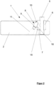
- the figure 1 shows in the perspective representation in the partially exploded representation a milling cutter 1, which is intended in particular to process transparent plastic material, such as acrylic glass.
- the milling cutter 1 in this case comprises a base body 2, which is disk-shaped in the example.
- the base body 2 is in this case fixed to a milling spindle, not shown in detail, with an opening 3 being located in the center of the base body 2, to which the base body 2 can be clamped on the spindle.
- up to four milling tools 4 are embedded in the region of the periphery of the disc-shaped base body 2 and protrude beyond the plane of the base body.
- the milling tools 4 are embodied as cutting pins 5, with some of the milling tools 4 being embodied as rough cutters and the others as finishing cutters, so that surfaces to be machined no longer have to be repolished.
- the cutting pins 5 are clamped in insert holders 6 , the individual insert holder 6 being in an existing one in the base body 2 Receiving pocket 7 is fixed.
- the insert holder 6 in the receiving pocket 7 can be inserted into the receiving pocket 7 under the action of a self-tightening device 8, the insert holder 6 being shown by the device 8 in the inserted state in FIG figure 2 , is fixed.
- the device 8 comprises a clamping bolt 9 mounted in the base body 2 and which locks the insert holder 6 in the receiving pocket 7 in the inserted state, as is shown in FIG figure 2 is shown.
- the clamping bolt 9 which is under a spring effect, is arranged in the base body 2 in an inclined position.
- the clamping bolt 9 has a spherical head 10 which is connected to the spring in the sloping receptacle 11 in relation to a spring which is not shown in detail.
- the spherical head 10 protrudes in this case partially through the wall 12 of the receiving pocket 7, as can be seen from the synopsis of figure 2 and 3 becomes recognizable.
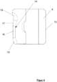
- the insert holder 6 has a guide pocket 14 in its wall 13 for the spherical head 10 of the clamping bolt 9 .
- the guide pocket 14 in its design is here in particular in the figure 3 , but also in the figure 4 shown in more detail, where in particular the insert holder 6 is shown in the sectional view.
- the guide pocket 14 has a beveled alignment surface 15 on the insertion side, which is intended in particular so that when the insert holder 6 is inserted into the receiving pocket 7, the insert holder 6 is first threaded into the opening area of the receiving pocket 7, with the alignment surface 15 then eventually contacting the spherical Head 10 comes into contact, so that then a corresponding alignment of the insert holder 6 relative to the base body 2 is given.
- a clearance area 18 for the head 10 in the clamped state adjoins the clamping surface 17, as can be seen in particular from FIG figure 2 is recognizable.
- slightly laid back clamping surface 17 engages behind the head 10 in the clamped state when the insert holder 6 is pressed into the receiving pocket 7, with the head 10 being guided on the guide surface 16 during the pressing process.
- the wall 12 of the receiving pocket 7 has at least 2 surface strips 19 which are in the figure 1 are only indicated, these surface strips 19 are arranged opposite the clamping bolt 9 .
- the two surface strokes 19 thus form a triangular bracing with the latched clamping bolt 9, which brings about the axial alignment of the insert holder 6 in the receiving pocket.
- a hole 20 corresponding to the clamping bolt 9 is provided in the base body 2 for unlocking, through which a pin-like tool can be inserted, with which the spherical head 10 can then be pushed back in the receptacle 11 for unlocking, in order in this way to be able to remove the insert holder 6 from the receiving pocket 7 by means of a magnet, not shown in detail.
Landscapes
- Engineering & Computer Science (AREA)
- Mechanical Engineering (AREA)
- Milling Processes (AREA)
Claims (7)
- Fraise (1) pour l'usinage de matériaux à base de matière plastique, comprenant un corps de base en forme de disque (2), qui peut être fixé sur une broche de fraisage,sachant que dans la zone de la périphérie du corps de base en forme de disque (2), sont introduits des outils de fraisage (4) dépassant sur le plan du corps de base, constitués sous la forme de tiges coupantes (5), qui sont serrés dans des supports insérables (6), etsachant que le support insérable (6) individuel est fixé dans une alvéole de logement (7) existant dans le corps de base (2),caractérisée en ce quele support insérable (6) dans l'alvéole de logement (7) peut être inséré dans l'alvéole de logement (7) sous l'action d'un dispositif auto-serrant (8), etsachant que le support insérable (6) est fixé par le dispositif (8) à l'état inséré,sachant que le dispositif (8) comprend un boulon de serrage (9) disposé dans une position inclinée dans le corps de base (2), se trouvant sous l'effet d'un ressort, qui enclenche à l'état inséré, le support insérable (6) dans l'alvéole de logement (7).
- Fraise (1) selon la revendication 1,
caractérisée en ce que
le boulon de serrage (9) dépasse avec sa tête sphérique (10) à travers la zone de paroi (12) de l'alvéole de logement (7). - Fraise (1) selon les revendications 1 à 2,
caractérisée en ce que
le support insérable (6) comporte dans sa paroi (13) une alvéole de guidage (14) pour la tête (10) du boulon de serrage (9). - Fraise (1) selon les revendications 1 à 3,
caractérisée en ce que
l'alvéole de guidage (14) comporte du côté introduction une surface d'orientation (15) chanfreinée pour le support insérable (6) dans l'alvéole de logement (7). - Fraise (1) selon les revendications 1 à 4,
caractérisée en ce qu'
une surface de guidage linéaire (16) et une surface de serrage chanfreinée (17) pour la tête (10) se raccordent à la surface d'orientation (15), sachant que la surface de serrage (17) passe à l'état serré dans une surface libre (18) pour la tête (10). - Fraise (1) selon les revendications 1 à 5,
caractérisée en ce que
la paroi (12) de l'alvéole de logement (7) comporte au moins deux bandes de surface (19) opposées au boulon de serrage (9). - Fraise (1) selon les revendications 1 à 6,
caractérisée en ce qu'
un trou (20) correspondant au boulon de serrage (9) est prévu dans le corps de base (2) pour le déverrouillage.
Priority Applications (1)
| Application Number | Priority Date | Filing Date | Title |
|---|---|---|---|
| EP18167631.3A EP3556499B1 (fr) | 2018-04-17 | 2018-04-17 | Fraiseuse destinée à l'usinage de matériaux plastiques |
Applications Claiming Priority (1)
| Application Number | Priority Date | Filing Date | Title |
|---|---|---|---|
| EP18167631.3A EP3556499B1 (fr) | 2018-04-17 | 2018-04-17 | Fraiseuse destinée à l'usinage de matériaux plastiques |
Publications (2)
| Publication Number | Publication Date |
|---|---|
| EP3556499A1 EP3556499A1 (fr) | 2019-10-23 |
| EP3556499B1 true EP3556499B1 (fr) | 2023-06-14 |
Family
ID=62017178
Family Applications (1)
| Application Number | Title | Priority Date | Filing Date |
|---|---|---|---|
| EP18167631.3A Active EP3556499B1 (fr) | 2018-04-17 | 2018-04-17 | Fraiseuse destinée à l'usinage de matériaux plastiques |
Country Status (1)
| Country | Link |
|---|---|
| EP (1) | EP3556499B1 (fr) |
Families Citing this family (1)
| Publication number | Priority date | Publication date | Assignee | Title |
|---|---|---|---|---|
| CN113681838B (zh) * | 2021-08-17 | 2022-11-08 | 苏州市百诺塑胶有限责任公司 | 一种铣胶口设备 |
Family Cites Families (5)
| Publication number | Priority date | Publication date | Assignee | Title |
|---|---|---|---|---|
| US3378901A (en) * | 1965-10-21 | 1968-04-23 | Goddard & Goddard Company | Milling cutter |
| GB1160425A (en) | 1966-07-20 | 1969-08-06 | Marsh Brothers & Co Ltd | Improvements in or relating to Cutting Tools. |
| DD280272A1 (de) | 1989-03-02 | 1990-07-04 | Karl Marx Stadt Ind Werke | Messerkopf mit schrupp- und schlichtschneiden |
| US5054972A (en) * | 1990-05-15 | 1991-10-08 | Cooney Kevin G | Rotary tool for sharpening studs in snowmobile treads |
| DE19947946B4 (de) | 1999-10-06 | 2005-03-17 | Muñoz, Gonzalo Tello | Fräser zur Bearbeitung von insbesondere transparenten Kunststoffmaterialien |
-
2018
- 2018-04-17 EP EP18167631.3A patent/EP3556499B1/fr active Active
Also Published As
| Publication number | Publication date |
|---|---|
| EP3556499A1 (fr) | 2019-10-23 |
Similar Documents
| Publication | Publication Date | Title |
|---|---|---|
| DE69825586T3 (de) | Schneidwerkzeuganordnung und austauschbarer schneidkopf dafür | |
| DE1627012C3 (de) | Bohrkopf o.dgl. Werkzeughalter | |
| EP1839788B1 (fr) | Mesure d'ébavurage pour un outil d'ébavurage | |
| CH678834A5 (fr) | ||
| DE1298845B (de) | Metallbearbeitungswerkzeug | |
| DE4032176C2 (de) | Scheibenschneider | |
| DE2502183B2 (de) | Einlippenbohrer | |
| DE7528316U (de) | Spitzbohrwerkzeug | |
| WO2001028718A1 (fr) | Outil a enlevement de copeaux pour usinage a vitesse elevee | |
| DE4212709C2 (de) | Werkzeug mit einem austauschbaren, einen zylindrischen Schaft aufweisenden Schneidkörper für die spanabhebende Formgebung, vornehmlich in der Metallbearbeitung | |
| EP3556499B1 (fr) | Fraiseuse destinée à l'usinage de matériaux plastiques | |
| DE1063878B (de) | In axialer Richtung hinterschnittener, in einem Halter eingeklemmter Schaftformstahl | |
| DE2234854A1 (de) | Werkzeug zur spanabhebenden bearbeitung, insbesondere fraesmesserkopf zum schlichten von werkstuecken | |
| DE3411557A1 (de) | Schneidwerkzeug zum herstellen von loechern | |
| DE102010003569A1 (de) | Methode zur Montage eines Innenrundschleifwerkzeugs | |
| DE102004014842B4 (de) | Um seine Achse rotierendes Werkzeug | |
| DE102019111986B3 (de) | Verfahren zum Schärfen eines in einen Messerkopf einsetzbaren Messers und Messerkopf mit geschärftem Messer | |
| DE396068C (de) | Umlaufendes Schneidwerkzeug mit in Nuten eingesetzten Messern | |
| EP3623089B1 (fr) | Outil de coupe doté d'un un corps de coupe | |
| CH654772A5 (de) | Werkzeug zum bohren von bohrungen in werkstuecken. | |
| DE3116326A1 (de) | Buerstenwerkzeug zum entgraten | |
| DE102024116340A1 (de) | Vorrichtung zur Begrenzung der Eingriffstiefe eines Zerspanungswerkzeugs | |
| DE202024103108U1 (de) | Vorrichtung zur Begrenzung der Eingriffstiefe eines Zerspanungswerkzeugs | |
| DE1552484C3 (de) | Kreisschneid-Apparat zur Herstellung runder Werkstück-Öffnungen | |
| DE2008789C (de) | Knopfformungsmaschine |
Legal Events
| Date | Code | Title | Description |
|---|---|---|---|
| PUAI | Public reference made under article 153(3) epc to a published international application that has entered the european phase |
Free format text: ORIGINAL CODE: 0009012 |
|
| STAA | Information on the status of an ep patent application or granted ep patent |
Free format text: STATUS: THE APPLICATION HAS BEEN PUBLISHED |
|
| AK | Designated contracting states |
Kind code of ref document: A1 Designated state(s): AL AT BE BG CH CY CZ DE DK EE ES FI FR GB GR HR HU IE IS IT LI LT LU LV MC MK MT NL NO PL PT RO RS SE SI SK SM TR |
|
| AX | Request for extension of the european patent |
Extension state: BA ME |
|
| STAA | Information on the status of an ep patent application or granted ep patent |
Free format text: STATUS: REQUEST FOR EXAMINATION WAS MADE |
|
| 17P | Request for examination filed |
Effective date: 20200421 |
|
| RBV | Designated contracting states (corrected) |
Designated state(s): AL AT BE BG CH CY CZ DE DK EE ES FI FR GB GR HR HU IE IS IT LI LT LU LV MC MK MT NL NO PL PT RO RS SE SI SK SM TR |
|
| STAA | Information on the status of an ep patent application or granted ep patent |
Free format text: STATUS: EXAMINATION IS IN PROGRESS |
|
| 17Q | First examination report despatched |
Effective date: 20220309 |
|
| GRAP | Despatch of communication of intention to grant a patent |
Free format text: ORIGINAL CODE: EPIDOSNIGR1 |
|
| STAA | Information on the status of an ep patent application or granted ep patent |
Free format text: STATUS: GRANT OF PATENT IS INTENDED |
|
| INTG | Intention to grant announced |
Effective date: 20230125 |
|
| GRAS | Grant fee paid |
Free format text: ORIGINAL CODE: EPIDOSNIGR3 |
|
| GRAA | (expected) grant |
Free format text: ORIGINAL CODE: 0009210 |
|
| STAA | Information on the status of an ep patent application or granted ep patent |
Free format text: STATUS: THE PATENT HAS BEEN GRANTED |
|
| AK | Designated contracting states |
Kind code of ref document: B1 Designated state(s): AL AT BE BG CH CY CZ DE DK EE ES FI FR GB GR HR HU IE IS IT LI LT LU LV MC MK MT NL NO PL PT RO RS SE SI SK SM TR |
|
| REG | Reference to a national code |
Ref country code: CH Ref legal event code: EP |
|
| REG | Reference to a national code |
Ref country code: DE Ref legal event code: R096 Ref document number: 502018012450 Country of ref document: DE |
|
| REG | Reference to a national code |
Ref country code: AT Ref legal event code: REF Ref document number: 1578863 Country of ref document: AT Kind code of ref document: T Effective date: 20230715 |
|
| REG | Reference to a national code |
Ref country code: LT Ref legal event code: MG9D |
|
| REG | Reference to a national code |
Ref country code: NL Ref legal event code: MP Effective date: 20230614 |
|
| PG25 | Lapsed in a contracting state [announced via postgrant information from national office to epo] |
Ref country code: SE Free format text: LAPSE BECAUSE OF FAILURE TO SUBMIT A TRANSLATION OF THE DESCRIPTION OR TO PAY THE FEE WITHIN THE PRESCRIBED TIME-LIMIT Effective date: 20230614 Ref country code: NO Free format text: LAPSE BECAUSE OF FAILURE TO SUBMIT A TRANSLATION OF THE DESCRIPTION OR TO PAY THE FEE WITHIN THE PRESCRIBED TIME-LIMIT Effective date: 20230914 Ref country code: ES Free format text: LAPSE BECAUSE OF FAILURE TO SUBMIT A TRANSLATION OF THE DESCRIPTION OR TO PAY THE FEE WITHIN THE PRESCRIBED TIME-LIMIT Effective date: 20230614 |
|
| PG25 | Lapsed in a contracting state [announced via postgrant information from national office to epo] |
Ref country code: RS Free format text: LAPSE BECAUSE OF FAILURE TO SUBMIT A TRANSLATION OF THE DESCRIPTION OR TO PAY THE FEE WITHIN THE PRESCRIBED TIME-LIMIT Effective date: 20230614 Ref country code: NL Free format text: LAPSE BECAUSE OF FAILURE TO SUBMIT A TRANSLATION OF THE DESCRIPTION OR TO PAY THE FEE WITHIN THE PRESCRIBED TIME-LIMIT Effective date: 20230614 Ref country code: LV Free format text: LAPSE BECAUSE OF FAILURE TO SUBMIT A TRANSLATION OF THE DESCRIPTION OR TO PAY THE FEE WITHIN THE PRESCRIBED TIME-LIMIT Effective date: 20230614 Ref country code: LT Free format text: LAPSE BECAUSE OF FAILURE TO SUBMIT A TRANSLATION OF THE DESCRIPTION OR TO PAY THE FEE WITHIN THE PRESCRIBED TIME-LIMIT Effective date: 20230614 Ref country code: HR Free format text: LAPSE BECAUSE OF FAILURE TO SUBMIT A TRANSLATION OF THE DESCRIPTION OR TO PAY THE FEE WITHIN THE PRESCRIBED TIME-LIMIT Effective date: 20230614 Ref country code: GR Free format text: LAPSE BECAUSE OF FAILURE TO SUBMIT A TRANSLATION OF THE DESCRIPTION OR TO PAY THE FEE WITHIN THE PRESCRIBED TIME-LIMIT Effective date: 20230915 |
|
| PG25 | Lapsed in a contracting state [announced via postgrant information from national office to epo] |
Ref country code: FI Free format text: LAPSE BECAUSE OF FAILURE TO SUBMIT A TRANSLATION OF THE DESCRIPTION OR TO PAY THE FEE WITHIN THE PRESCRIBED TIME-LIMIT Effective date: 20230614 |
|
| PG25 | Lapsed in a contracting state [announced via postgrant information from national office to epo] |
Ref country code: SK Free format text: LAPSE BECAUSE OF FAILURE TO SUBMIT A TRANSLATION OF THE DESCRIPTION OR TO PAY THE FEE WITHIN THE PRESCRIBED TIME-LIMIT Effective date: 20230614 |
|
| PG25 | Lapsed in a contracting state [announced via postgrant information from national office to epo] |
Ref country code: IS Free format text: LAPSE BECAUSE OF FAILURE TO SUBMIT A TRANSLATION OF THE DESCRIPTION OR TO PAY THE FEE WITHIN THE PRESCRIBED TIME-LIMIT Effective date: 20231014 |
|
| PG25 | Lapsed in a contracting state [announced via postgrant information from national office to epo] |
Ref country code: SM Free format text: LAPSE BECAUSE OF FAILURE TO SUBMIT A TRANSLATION OF THE DESCRIPTION OR TO PAY THE FEE WITHIN THE PRESCRIBED TIME-LIMIT Effective date: 20230614 Ref country code: SK Free format text: LAPSE BECAUSE OF FAILURE TO SUBMIT A TRANSLATION OF THE DESCRIPTION OR TO PAY THE FEE WITHIN THE PRESCRIBED TIME-LIMIT Effective date: 20230614 Ref country code: RO Free format text: LAPSE BECAUSE OF FAILURE TO SUBMIT A TRANSLATION OF THE DESCRIPTION OR TO PAY THE FEE WITHIN THE PRESCRIBED TIME-LIMIT Effective date: 20230614 Ref country code: PT Free format text: LAPSE BECAUSE OF FAILURE TO SUBMIT A TRANSLATION OF THE DESCRIPTION OR TO PAY THE FEE WITHIN THE PRESCRIBED TIME-LIMIT Effective date: 20231016 Ref country code: IS Free format text: LAPSE BECAUSE OF FAILURE TO SUBMIT A TRANSLATION OF THE DESCRIPTION OR TO PAY THE FEE WITHIN THE PRESCRIBED TIME-LIMIT Effective date: 20231014 Ref country code: EE Free format text: LAPSE BECAUSE OF FAILURE TO SUBMIT A TRANSLATION OF THE DESCRIPTION OR TO PAY THE FEE WITHIN THE PRESCRIBED TIME-LIMIT Effective date: 20230614 Ref country code: CZ Free format text: LAPSE BECAUSE OF FAILURE TO SUBMIT A TRANSLATION OF THE DESCRIPTION OR TO PAY THE FEE WITHIN THE PRESCRIBED TIME-LIMIT Effective date: 20230614 |
|
| PG25 | Lapsed in a contracting state [announced via postgrant information from national office to epo] |
Ref country code: PL Free format text: LAPSE BECAUSE OF FAILURE TO SUBMIT A TRANSLATION OF THE DESCRIPTION OR TO PAY THE FEE WITHIN THE PRESCRIBED TIME-LIMIT Effective date: 20230614 |
|
| REG | Reference to a national code |
Ref country code: DE Ref legal event code: R097 Ref document number: 502018012450 Country of ref document: DE |
|
| PLBE | No opposition filed within time limit |
Free format text: ORIGINAL CODE: 0009261 |
|
| STAA | Information on the status of an ep patent application or granted ep patent |
Free format text: STATUS: NO OPPOSITION FILED WITHIN TIME LIMIT |
|
| PG25 | Lapsed in a contracting state [announced via postgrant information from national office to epo] |
Ref country code: DK Free format text: LAPSE BECAUSE OF FAILURE TO SUBMIT A TRANSLATION OF THE DESCRIPTION OR TO PAY THE FEE WITHIN THE PRESCRIBED TIME-LIMIT Effective date: 20230614 |
|
| PG25 | Lapsed in a contracting state [announced via postgrant information from national office to epo] |
Ref country code: SI Free format text: LAPSE BECAUSE OF FAILURE TO SUBMIT A TRANSLATION OF THE DESCRIPTION OR TO PAY THE FEE WITHIN THE PRESCRIBED TIME-LIMIT Effective date: 20230614 |
|
| 26N | No opposition filed |
Effective date: 20240315 |
|
| PG25 | Lapsed in a contracting state [announced via postgrant information from national office to epo] |
Ref country code: SI Free format text: LAPSE BECAUSE OF FAILURE TO SUBMIT A TRANSLATION OF THE DESCRIPTION OR TO PAY THE FEE WITHIN THE PRESCRIBED TIME-LIMIT Effective date: 20230614 Ref country code: IT Free format text: LAPSE BECAUSE OF FAILURE TO SUBMIT A TRANSLATION OF THE DESCRIPTION OR TO PAY THE FEE WITHIN THE PRESCRIBED TIME-LIMIT Effective date: 20230614 |
|
| PGFP | Annual fee paid to national office [announced via postgrant information from national office to epo] |
Ref country code: DE Payment date: 20240430 Year of fee payment: 7 |
|
| PG25 | Lapsed in a contracting state [announced via postgrant information from national office to epo] |
Ref country code: BG Free format text: LAPSE BECAUSE OF FAILURE TO SUBMIT A TRANSLATION OF THE DESCRIPTION OR TO PAY THE FEE WITHIN THE PRESCRIBED TIME-LIMIT Effective date: 20230614 |
|
| PG25 | Lapsed in a contracting state [announced via postgrant information from national office to epo] |
Ref country code: MC Free format text: LAPSE BECAUSE OF FAILURE TO SUBMIT A TRANSLATION OF THE DESCRIPTION OR TO PAY THE FEE WITHIN THE PRESCRIBED TIME-LIMIT Effective date: 20230614 |
|
| PG25 | Lapsed in a contracting state [announced via postgrant information from national office to epo] |
Ref country code: MC Free format text: LAPSE BECAUSE OF FAILURE TO SUBMIT A TRANSLATION OF THE DESCRIPTION OR TO PAY THE FEE WITHIN THE PRESCRIBED TIME-LIMIT Effective date: 20230614 Ref country code: BG Free format text: LAPSE BECAUSE OF FAILURE TO SUBMIT A TRANSLATION OF THE DESCRIPTION OR TO PAY THE FEE WITHIN THE PRESCRIBED TIME-LIMIT Effective date: 20230614 |
|
| REG | Reference to a national code |
Ref country code: CH Ref legal event code: PL |
|
| PG25 | Lapsed in a contracting state [announced via postgrant information from national office to epo] |
Ref country code: LU Free format text: LAPSE BECAUSE OF NON-PAYMENT OF DUE FEES Effective date: 20240417 |
|
| GBPC | Gb: european patent ceased through non-payment of renewal fee |
Effective date: 20240417 |
|
| REG | Reference to a national code |
Ref country code: BE Ref legal event code: MM Effective date: 20240430 |
|
| PG25 | Lapsed in a contracting state [announced via postgrant information from national office to epo] |
Ref country code: LU Free format text: LAPSE BECAUSE OF NON-PAYMENT OF DUE FEES Effective date: 20240417 |
|
| PG25 | Lapsed in a contracting state [announced via postgrant information from national office to epo] |
Ref country code: BE Free format text: LAPSE BECAUSE OF NON-PAYMENT OF DUE FEES Effective date: 20240430 |
|
| PG25 | Lapsed in a contracting state [announced via postgrant information from national office to epo] |
Ref country code: GB Free format text: LAPSE BECAUSE OF NON-PAYMENT OF DUE FEES Effective date: 20240417 |
|
| PG25 | Lapsed in a contracting state [announced via postgrant information from national office to epo] |
Ref country code: FR Free format text: LAPSE BECAUSE OF NON-PAYMENT OF DUE FEES Effective date: 20240430 |
|
| PG25 | Lapsed in a contracting state [announced via postgrant information from national office to epo] |
Ref country code: GB Free format text: LAPSE BECAUSE OF NON-PAYMENT OF DUE FEES Effective date: 20240417 Ref country code: FR Free format text: LAPSE BECAUSE OF NON-PAYMENT OF DUE FEES Effective date: 20240430 Ref country code: BE Free format text: LAPSE BECAUSE OF NON-PAYMENT OF DUE FEES Effective date: 20240430 Ref country code: CH Free format text: LAPSE BECAUSE OF NON-PAYMENT OF DUE FEES Effective date: 20240430 |
|
| PG25 | Lapsed in a contracting state [announced via postgrant information from national office to epo] |
Ref country code: IE Free format text: LAPSE BECAUSE OF NON-PAYMENT OF DUE FEES Effective date: 20240417 |
|
| REG | Reference to a national code |
Ref country code: AT Ref legal event code: MM01 Ref document number: 1578863 Country of ref document: AT Kind code of ref document: T Effective date: 20240417 |
|
| PG25 | Lapsed in a contracting state [announced via postgrant information from national office to epo] |
Ref country code: AT Free format text: LAPSE BECAUSE OF NON-PAYMENT OF DUE FEES Effective date: 20240417 |
|
| PG25 | Lapsed in a contracting state [announced via postgrant information from national office to epo] |
Ref country code: CY Free format text: LAPSE BECAUSE OF FAILURE TO SUBMIT A TRANSLATION OF THE DESCRIPTION OR TO PAY THE FEE WITHIN THE PRESCRIBED TIME-LIMIT; INVALID AB INITIO Effective date: 20180417 |
|
| PG25 | Lapsed in a contracting state [announced via postgrant information from national office to epo] |
Ref country code: HU Free format text: LAPSE BECAUSE OF FAILURE TO SUBMIT A TRANSLATION OF THE DESCRIPTION OR TO PAY THE FEE WITHIN THE PRESCRIBED TIME-LIMIT; INVALID AB INITIO Effective date: 20180417 |
|
| REG | Reference to a national code |
Ref country code: DE Ref legal event code: R119 Ref document number: 502018012450 Country of ref document: DE |
|
| PG25 | Lapsed in a contracting state [announced via postgrant information from national office to epo] |
Ref country code: DE Free format text: LAPSE BECAUSE OF NON-PAYMENT OF DUE FEES Effective date: 20251104 |