EP3556499A1 - Fraiseuse destinée à l'usinage de matériaux plastiques - Google Patents
Fraiseuse destinée à l'usinage de matériaux plastiques Download PDFInfo
- Publication number
- EP3556499A1 EP3556499A1 EP18167631.3A EP18167631A EP3556499A1 EP 3556499 A1 EP3556499 A1 EP 3556499A1 EP 18167631 A EP18167631 A EP 18167631A EP 3556499 A1 EP3556499 A1 EP 3556499A1
- Authority
- EP
- European Patent Office
- Prior art keywords
- insert holder
- receiving pocket
- base body
- clamping
- clamping bolt
- Prior art date
- Legal status (The legal status is an assumption and is not a legal conclusion. Google has not performed a legal analysis and makes no representation as to the accuracy of the status listed.)
- Granted
Links
Images


Classifications
-
- B—PERFORMING OPERATIONS; TRANSPORTING
- B23—MACHINE TOOLS; METAL-WORKING NOT OTHERWISE PROVIDED FOR
- B23C—MILLING
- B23C5/00—Milling-cutters
- B23C5/16—Milling-cutters characterised by physical features other than shape
- B23C5/20—Milling-cutters characterised by physical features other than shape with removable cutter bits or teeth or cutting inserts
- B23C5/22—Securing arrangements for bits or teeth or cutting inserts
- B23C5/24—Securing arrangements for bits or teeth or cutting inserts adjustable
- B23C5/2462—Securing arrangements for bits or teeth or cutting inserts adjustable the adjusting means being oblique surfaces
Definitions
- the invention relates to a milling cutter for processing plastic materials, comprising a disc-shaped base body which can be fixed to a milling spindle, wherein in the periphery of the disc-shaped base body on the base body plane protruding, designed as cutting pins milling tools are embedded, which are clamped in insert holder and wherein the individual insert holder is fixed in an existing in the base receiving pocket.
- the cutter consists mainly of a base body which is formed as a disc, wherein in the center of the disc, an opening is present, in which the milling spindle is set to enable the disc in rotation.
- the milling spindle is set to enable the disc in rotation.
- pin-like milling tools are embedded, which are filled with diamonds as cutting material.
- the main body while two, three or four opposing milling tools are arranged, some being designed as a precutter and others as a final cutter.
- surfaces can be processed on a transparent plastic block, which are formed milled and polished.
- the milling tools consisting of holder and cutting pin itself are in the body in pockets that are formed as holes, embedded and clamped by means of clamping bolts therein.
- a cutter head with roughing and finishing cutting comprising a body that can be fixed to a milling spindle.
- a body that can be fixed to a milling spindle.
- Inserted milling tools are also in the periphery of the body beyond the main body plane protruding Inserted milling tools.
- the insert holders themselves are here inserted into circular pockets in the base body, wherein by means of a positioning pin of the insert holder and thus the milling tool in the main body can be aligned or fixed.
- Another cutter for processing is from the GB 11 60 425 A known, said cutting tool also has a base body which shows recessed in the region of a peripheral milling tools. Also in this embodiment of the prior art, the insert holder and thus the milling tool is aligned and fixed in the base body by means of a positioning pin.
- the cutter as such in this case likewise comprises a disc-shaped basic body which can be fixed to a milling spindle, wherein in the region of the periphery of the disc-shaped base body beyond the base body plane protruding, designed as cutting pins milling tools are embedded, which are braced in insert holder.
- the individual insert holder is fixed in a receiving pocket present in the main body by means of a positioning pin.
- the positioning pins are subdivided over their shaft length into three regions, the upper region for positioning the insert holder in the circular pocket, the middle region for clamping the insert holder in the base body and the lower region for mounting the positioning pin is determined in the body. So if you want to change the insert holder with the cutting pin, so it is necessary here that by means of a tool, the positioning pin is released, so that then the insert holder can be removed from the receiving pocket.
- the milling cutters known from the prior art have the particular disadvantage that the basic body designed as a disc on the one hand severely fails due to the required moment of inertia, on the other hand, the determination of the body on the spindle requires a complex adjustment work. It is therefore necessary if, for example, the milling tools must be changed or reground, that then the entire body must be removed from the spindle. Due to its weight, therefore, transport problems arise. Another problem is that different milling tools are to be kept for the individual operations, which have different adjustment parameters. For this, the tool axis of the machine must be readjusted with every tool change, which leads to downtimes in production.
- the invention thus raises the problem of developing a known milling cutter in such a way that is easier, faster and less expensive to handle with regard to the tool change.
- the advantages achieved by the invention result from the fact that in the inventive solution of the insert holder is inserted into the receiving pocket of the disc without tools, with alignment surfaces are present in the receiving pocket for radial alignment of the insert holder.
- To insert the insert holder is threaded into the receiving pocket until this is above the clamping bolt. Only in this position, the insert holder is then pressed into the receiving pocket.
- the alignment surface presses the clamping bolt down against a spring and puts it under tension.
- the guide surface prevents the insert holder from turning radially once again on the way down.
- the clamping bolt relaxes, slipping over the clamping surface. He presses the insert holder against the wall of the receiving pocket and the bottom of the receiving pocket.
- the fact that the clamping surface has a steeper angle than the linear path of the clamping bolt, the voltage increases on the insert holder when the ball of the clamping bolt slips over the clamping surface.
- the clamping bolt is pressed by a hole located in the top of the disc down, the insert holder is then pulled out by means of a magnet.
- the wall of the receiving pocket is not completely curved, but it is designed such that it has two surface strips relative to the clamping bolt.
- the clamping bolt thus presses the insert holder against these surfaces in the inserted state.
- the rest of the pocket wall is not touched.
- the two surfaces are arranged so that they form a triangle together with the clamping bolt to form a stable three-point position of the insert holder in the receiving pocket. This keeps the insert holder aligned in all axes.
- the insert holder can be inserted into the receiving pocket under the effect of a self-tensioning device and wherein the insert holder is fixed by the device in the inserted state. Due to this design is achieved, as already described, that a fast fixed and aligned use or change of the insert holder can be made in the disk-shaped spindle.
- the device comprises a clamping bolt mounted in the main body, which locks the insert holder in the receiving pocket in the inserted state.
- the clamping bolt is arranged in the body under an inclined position.
- the clamping bolt projects with its spherical head through the wall region of the receiving pocket.
- the insert holder in its wall on a guide pocket for the head of the clamping bolt.
- the guide pocket has a tapered alignment surface for the insert holder in the receiving pocket. The alignment makes it possible that with easy insertion of the cylindrical insert holder immediately the corresponding position is found, which is essential for the subsequent latching operation.
- the alignment surface is followed by a linear guide surface and a chamfered clamping surface for the spherical one Head on, wherein the clamping surface merges into an open space for the spherical head in the clamped state. Due to this design ensures that in particular after the insertion of the insert holder is done, quasi an inner backdrop for the ball head of the clamping bolt is provided, which is guided over the guide pocket here by the linear and by the undercut locking surface, so that the ball head its end position easy and easy to reach on the insert holder.
- the wall of the receiving pocket on at least two surface strips, which are arranged opposite the clamping bolt.
- this provides a radial default orientation for the insert holder, which is based on a three-point clamping, so that an exact alignment of the insert holder in the disk-shaped base body is thereby provided.
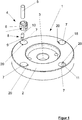
- the FIG. 1 shows in the perspective view in the partially exploded view of a milling cutter 1, which is particularly intended to edit transparent plastic material, such as acrylic glass.
- the cutter 1 in this case comprises a base body 2, which is disc-shaped in the example.
- the base body 2 is in this case fixed to a milling spindle, not shown, wherein in the center of the base body 2, there is an opening 3, to which the base body 2 can be clamped to the spindle.
- up to four milling tools 4 are embedded in the periphery of the disc-shaped base body 2, which protrude beyond the base body plane.
- the milling tools 4 are designed as cutting pins 5, wherein some of the milling tools 4 are formed as a precutter and the other as a final cutter, so that surfaces to be machined no longer need to be polished.
- the cutting pins 5 are clamped in insert holders 6, wherein the single insert holder 6 is fixed in an existing in the base body 2 receiving pocket 7.
- the insert holder 6 is inserted into the receiving pocket 7 under the action of a self-tensioning device 8 in the receiving pocket 7, wherein the insert holder 6 by the device 8 in the inserted state, shown in the FIG. 2 , is fixed.
- the device 8 comprises a clamping body 9 mounted in the base body 2, which locks the insert holder 6 in the receiving pocket 7 in the inserted state, as shown in the FIG. 2 is shown.
- the standing under a spring action clamping bolt 9 is arranged in the base body 2 at an oblique position.
- the clamping bolt 9 in this case has a spherical head 10, which is involved with respect to a spring not shown in the oblique receptacle 11 with the spring.
- the spherical head 10 protrudes partially through the wall 12 of the receiving pocket 7, as is apparent from the synopsis of FIG. 2 and 3 becomes recognizable.
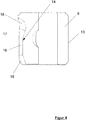
- the insert holder 6 in its wall 13 on a guide pocket 14 for the spherical head 10 of the clamping bolt 9.
- the guide pocket 14 in its configuration is in this case in particular in the FIG. 3 but also in the FIG. 4 shown in more detail, where in particular the insert holder 6 is shown in the sectional view.
- the guide pocket 14 has a tapered alignment surface 15 on the insertion side, which is intended in particular for threading the insert holder 6 into the receiving pocket 7, firstly threading the insert holder 6 in the opening region of the receiving pocket 7, the alignment surface 15 then becoming spherical at some point Head 10 comes into contact, so that then a corresponding orientation of the insert holder 6 relative to the base body 2 is given.
- the slightly recessed clamping surface 17 engages behind the head 10 in the clamped state when the insert holder 6 is pressed into the receiving pocket 7, wherein the head 10 is guided on the guide surface 16 during the pressing operation.
- the wall 12 of the receiving pocket 7 at least 2 surface strips 19, which in the FIG. 1 only indicated, these surface strips 19 are arranged opposite the clamping bolt 9.
- the two surface coatings 19 thus form a latched tension with the latched clamping bolt 9, which effect the axial alignment of the insert holder 6 in the receiving pocket.
- a corresponding with the clamping bolt 9 hole 20 is provided in the base body 2, through which a pin-like tool can be inserted, with which you can then press back to unlock the spherical head 10 in the receptacle 11, in order to unlock to be able to remove the insert holder 6 from the receiving pocket 7 by means of a magnet, not shown.
Landscapes
- Engineering & Computer Science (AREA)
- Mechanical Engineering (AREA)
- Milling Processes (AREA)
Priority Applications (1)
| Application Number | Priority Date | Filing Date | Title |
|---|---|---|---|
| EP18167631.3A EP3556499B1 (fr) | 2018-04-17 | 2018-04-17 | Fraiseuse destinée à l'usinage de matériaux plastiques |
Applications Claiming Priority (1)
| Application Number | Priority Date | Filing Date | Title |
|---|---|---|---|
| EP18167631.3A EP3556499B1 (fr) | 2018-04-17 | 2018-04-17 | Fraiseuse destinée à l'usinage de matériaux plastiques |
Publications (2)
| Publication Number | Publication Date |
|---|---|
| EP3556499A1 true EP3556499A1 (fr) | 2019-10-23 |
| EP3556499B1 EP3556499B1 (fr) | 2023-06-14 |
Family
ID=62017178
Family Applications (1)
| Application Number | Title | Priority Date | Filing Date |
|---|---|---|---|
| EP18167631.3A Active EP3556499B1 (fr) | 2018-04-17 | 2018-04-17 | Fraiseuse destinée à l'usinage de matériaux plastiques |
Country Status (1)
| Country | Link |
|---|---|
| EP (1) | EP3556499B1 (fr) |
Cited By (1)
| Publication number | Priority date | Publication date | Assignee | Title |
|---|---|---|---|---|
| CN113681838A (zh) * | 2021-08-17 | 2021-11-23 | 苏州市百诺塑胶有限责任公司 | 一种铣胶口设备 |
Citations (5)
| Publication number | Priority date | Publication date | Assignee | Title |
|---|---|---|---|---|
| US3378901A (en) * | 1965-10-21 | 1968-04-23 | Goddard & Goddard Company | Milling cutter |
| GB1160425A (en) | 1966-07-20 | 1969-08-06 | Marsh Brothers & Co Ltd | Improvements in or relating to Cutting Tools. |
| DD280272A1 (de) | 1989-03-02 | 1990-07-04 | Karl Marx Stadt Ind Werke | Messerkopf mit schrupp- und schlichtschneiden |
| US5054972A (en) * | 1990-05-15 | 1991-10-08 | Cooney Kevin G | Rotary tool for sharpening studs in snowmobile treads |
| DE19947946A1 (de) | 1999-10-06 | 2001-04-19 | Gonzalo Tello Munoz | Fräser zur Bearbeitung von insbesondere transparenten Kunststoffmaterialien |
-
2018
- 2018-04-17 EP EP18167631.3A patent/EP3556499B1/fr active Active
Patent Citations (5)
| Publication number | Priority date | Publication date | Assignee | Title |
|---|---|---|---|---|
| US3378901A (en) * | 1965-10-21 | 1968-04-23 | Goddard & Goddard Company | Milling cutter |
| GB1160425A (en) | 1966-07-20 | 1969-08-06 | Marsh Brothers & Co Ltd | Improvements in or relating to Cutting Tools. |
| DD280272A1 (de) | 1989-03-02 | 1990-07-04 | Karl Marx Stadt Ind Werke | Messerkopf mit schrupp- und schlichtschneiden |
| US5054972A (en) * | 1990-05-15 | 1991-10-08 | Cooney Kevin G | Rotary tool for sharpening studs in snowmobile treads |
| DE19947946A1 (de) | 1999-10-06 | 2001-04-19 | Gonzalo Tello Munoz | Fräser zur Bearbeitung von insbesondere transparenten Kunststoffmaterialien |
Cited By (2)
| Publication number | Priority date | Publication date | Assignee | Title |
|---|---|---|---|---|
| CN113681838A (zh) * | 2021-08-17 | 2021-11-23 | 苏州市百诺塑胶有限责任公司 | 一种铣胶口设备 |
| CN113681838B (zh) * | 2021-08-17 | 2022-11-08 | 苏州市百诺塑胶有限责任公司 | 一种铣胶口设备 |
Also Published As
| Publication number | Publication date |
|---|---|
| EP3556499B1 (fr) | 2023-06-14 |
Similar Documents
| Publication | Publication Date | Title |
|---|---|---|
| DE1627012C3 (de) | Bohrkopf o.dgl. Werkzeughalter | |
| DE2452681C3 (de) | Rotierendes Werkzeug zur spanabhebenden Bearbeitung | |
| WO2014127391A1 (fr) | Outil de fraisage | |
| CH678834A5 (fr) | ||
| EP2266732B1 (fr) | Système de serrage | |
| DE102016222595B4 (de) | Verfahren und Fräswerkzeug zur Herstellung einer Kavität in einem Werkstück für die Aufnahme einer Zentrierspitze | |
| DE102015115548A1 (de) | Stabmesserkopf | |
| EP0287777A2 (fr) | Dispositif de serrage d'outils ou de pièces, ayant une manche cylindrique | |
| DE2112092A1 (de) | Werkzeughalter | |
| DE1232436B (de) | Mehrschneidiger Schneidkoerper aus hartem Schneidwerkstoff | |
| EP3556499A1 (fr) | Fraiseuse destinée à l'usinage de matériaux plastiques | |
| DE2802324A1 (de) | Bearbeitungswerkzeug | |
| DE3220363C2 (de) | Fräsmesserkopf für Schruppbearbeitung | |
| DE1502083A1 (de) | Verbesserungen an Fraesern | |
| DE202020102054U1 (de) | Werkzeughalter mit einer als Schrumpffutter ausgebildeten Aufnahme in Form einer Hülse | |
| DE29723558U1 (de) | Fräswerkzeug | |
| DE69033337T2 (de) | Rohrendbearbeitungswerkzeug mit verbesserten Torsionreaktion und Spannmöglichkeiten | |
| DE29810851U1 (de) | Schneidwerkzeug-Anordnung | |
| DE202020004775U1 (de) | Schnellwechselsystem zur Werkzeugbefestigung | |
| EP3170595B1 (fr) | Porte-outil | |
| DE1752202A1 (de) | Schneidwerkzeugeinsatz und Halter fuer diesen | |
| DE2522735A1 (de) | Umkehrbarer schneideinsatz | |
| DE3638068C1 (de) | Fraesvorrichtung zum Bearbeiten,insbesondere Besaeumen,der Kanten von Blechbaendern,Blechplatten oder dgl. | |
| DE202018105149U1 (de) | Spannfutter mit einer Aufnahme für einen Schaft eines zylindrischen Rotationswerkzeuges | |
| EP3623089B1 (fr) | Outil de coupe doté d'un un corps de coupe |
Legal Events
| Date | Code | Title | Description |
|---|---|---|---|
| PUAI | Public reference made under article 153(3) epc to a published international application that has entered the european phase |
Free format text: ORIGINAL CODE: 0009012 |
|
| STAA | Information on the status of an ep patent application or granted ep patent |
Free format text: STATUS: THE APPLICATION HAS BEEN PUBLISHED |
|
| AK | Designated contracting states |
Kind code of ref document: A1 Designated state(s): AL AT BE BG CH CY CZ DE DK EE ES FI FR GB GR HR HU IE IS IT LI LT LU LV MC MK MT NL NO PL PT RO RS SE SI SK SM TR |
|
| AX | Request for extension of the european patent |
Extension state: BA ME |
|
| STAA | Information on the status of an ep patent application or granted ep patent |
Free format text: STATUS: REQUEST FOR EXAMINATION WAS MADE |
|
| 17P | Request for examination filed |
Effective date: 20200421 |
|
| RBV | Designated contracting states (corrected) |
Designated state(s): AL AT BE BG CH CY CZ DE DK EE ES FI FR GB GR HR HU IE IS IT LI LT LU LV MC MK MT NL NO PL PT RO RS SE SI SK SM TR |
|
| STAA | Information on the status of an ep patent application or granted ep patent |
Free format text: STATUS: EXAMINATION IS IN PROGRESS |
|
| 17Q | First examination report despatched |
Effective date: 20220309 |
|
| GRAP | Despatch of communication of intention to grant a patent |
Free format text: ORIGINAL CODE: EPIDOSNIGR1 |
|
| STAA | Information on the status of an ep patent application or granted ep patent |
Free format text: STATUS: GRANT OF PATENT IS INTENDED |
|
| INTG | Intention to grant announced |
Effective date: 20230125 |
|
| GRAS | Grant fee paid |
Free format text: ORIGINAL CODE: EPIDOSNIGR3 |
|
| GRAA | (expected) grant |
Free format text: ORIGINAL CODE: 0009210 |
|
| STAA | Information on the status of an ep patent application or granted ep patent |
Free format text: STATUS: THE PATENT HAS BEEN GRANTED |
|
| AK | Designated contracting states |
Kind code of ref document: B1 Designated state(s): AL AT BE BG CH CY CZ DE DK EE ES FI FR GB GR HR HU IE IS IT LI LT LU LV MC MK MT NL NO PL PT RO RS SE SI SK SM TR |
|
| REG | Reference to a national code |
Ref country code: CH Ref legal event code: EP |
|
| REG | Reference to a national code |
Ref country code: DE Ref legal event code: R096 Ref document number: 502018012450 Country of ref document: DE |
|
| REG | Reference to a national code |
Ref country code: AT Ref legal event code: REF Ref document number: 1578863 Country of ref document: AT Kind code of ref document: T Effective date: 20230715 |
|
| REG | Reference to a national code |
Ref country code: LT Ref legal event code: MG9D |
|
| REG | Reference to a national code |
Ref country code: NL Ref legal event code: MP Effective date: 20230614 |
|
| PG25 | Lapsed in a contracting state [announced via postgrant information from national office to epo] |
Ref country code: SE Free format text: LAPSE BECAUSE OF FAILURE TO SUBMIT A TRANSLATION OF THE DESCRIPTION OR TO PAY THE FEE WITHIN THE PRESCRIBED TIME-LIMIT Effective date: 20230614 Ref country code: NO Free format text: LAPSE BECAUSE OF FAILURE TO SUBMIT A TRANSLATION OF THE DESCRIPTION OR TO PAY THE FEE WITHIN THE PRESCRIBED TIME-LIMIT Effective date: 20230914 Ref country code: ES Free format text: LAPSE BECAUSE OF FAILURE TO SUBMIT A TRANSLATION OF THE DESCRIPTION OR TO PAY THE FEE WITHIN THE PRESCRIBED TIME-LIMIT Effective date: 20230614 |
|
| PG25 | Lapsed in a contracting state [announced via postgrant information from national office to epo] |
Ref country code: RS Free format text: LAPSE BECAUSE OF FAILURE TO SUBMIT A TRANSLATION OF THE DESCRIPTION OR TO PAY THE FEE WITHIN THE PRESCRIBED TIME-LIMIT Effective date: 20230614 Ref country code: NL Free format text: LAPSE BECAUSE OF FAILURE TO SUBMIT A TRANSLATION OF THE DESCRIPTION OR TO PAY THE FEE WITHIN THE PRESCRIBED TIME-LIMIT Effective date: 20230614 Ref country code: LV Free format text: LAPSE BECAUSE OF FAILURE TO SUBMIT A TRANSLATION OF THE DESCRIPTION OR TO PAY THE FEE WITHIN THE PRESCRIBED TIME-LIMIT Effective date: 20230614 Ref country code: LT Free format text: LAPSE BECAUSE OF FAILURE TO SUBMIT A TRANSLATION OF THE DESCRIPTION OR TO PAY THE FEE WITHIN THE PRESCRIBED TIME-LIMIT Effective date: 20230614 Ref country code: HR Free format text: LAPSE BECAUSE OF FAILURE TO SUBMIT A TRANSLATION OF THE DESCRIPTION OR TO PAY THE FEE WITHIN THE PRESCRIBED TIME-LIMIT Effective date: 20230614 Ref country code: GR Free format text: LAPSE BECAUSE OF FAILURE TO SUBMIT A TRANSLATION OF THE DESCRIPTION OR TO PAY THE FEE WITHIN THE PRESCRIBED TIME-LIMIT Effective date: 20230915 |
|
| PG25 | Lapsed in a contracting state [announced via postgrant information from national office to epo] |
Ref country code: FI Free format text: LAPSE BECAUSE OF FAILURE TO SUBMIT A TRANSLATION OF THE DESCRIPTION OR TO PAY THE FEE WITHIN THE PRESCRIBED TIME-LIMIT Effective date: 20230614 |
|
| PG25 | Lapsed in a contracting state [announced via postgrant information from national office to epo] |
Ref country code: SK Free format text: LAPSE BECAUSE OF FAILURE TO SUBMIT A TRANSLATION OF THE DESCRIPTION OR TO PAY THE FEE WITHIN THE PRESCRIBED TIME-LIMIT Effective date: 20230614 |
|
| PG25 | Lapsed in a contracting state [announced via postgrant information from national office to epo] |
Ref country code: IS Free format text: LAPSE BECAUSE OF FAILURE TO SUBMIT A TRANSLATION OF THE DESCRIPTION OR TO PAY THE FEE WITHIN THE PRESCRIBED TIME-LIMIT Effective date: 20231014 |
|
| PG25 | Lapsed in a contracting state [announced via postgrant information from national office to epo] |
Ref country code: SM Free format text: LAPSE BECAUSE OF FAILURE TO SUBMIT A TRANSLATION OF THE DESCRIPTION OR TO PAY THE FEE WITHIN THE PRESCRIBED TIME-LIMIT Effective date: 20230614 Ref country code: SK Free format text: LAPSE BECAUSE OF FAILURE TO SUBMIT A TRANSLATION OF THE DESCRIPTION OR TO PAY THE FEE WITHIN THE PRESCRIBED TIME-LIMIT Effective date: 20230614 Ref country code: RO Free format text: LAPSE BECAUSE OF FAILURE TO SUBMIT A TRANSLATION OF THE DESCRIPTION OR TO PAY THE FEE WITHIN THE PRESCRIBED TIME-LIMIT Effective date: 20230614 Ref country code: PT Free format text: LAPSE BECAUSE OF FAILURE TO SUBMIT A TRANSLATION OF THE DESCRIPTION OR TO PAY THE FEE WITHIN THE PRESCRIBED TIME-LIMIT Effective date: 20231016 Ref country code: IS Free format text: LAPSE BECAUSE OF FAILURE TO SUBMIT A TRANSLATION OF THE DESCRIPTION OR TO PAY THE FEE WITHIN THE PRESCRIBED TIME-LIMIT Effective date: 20231014 Ref country code: EE Free format text: LAPSE BECAUSE OF FAILURE TO SUBMIT A TRANSLATION OF THE DESCRIPTION OR TO PAY THE FEE WITHIN THE PRESCRIBED TIME-LIMIT Effective date: 20230614 Ref country code: CZ Free format text: LAPSE BECAUSE OF FAILURE TO SUBMIT A TRANSLATION OF THE DESCRIPTION OR TO PAY THE FEE WITHIN THE PRESCRIBED TIME-LIMIT Effective date: 20230614 |
|
| PG25 | Lapsed in a contracting state [announced via postgrant information from national office to epo] |
Ref country code: PL Free format text: LAPSE BECAUSE OF FAILURE TO SUBMIT A TRANSLATION OF THE DESCRIPTION OR TO PAY THE FEE WITHIN THE PRESCRIBED TIME-LIMIT Effective date: 20230614 |
|
| REG | Reference to a national code |
Ref country code: DE Ref legal event code: R097 Ref document number: 502018012450 Country of ref document: DE |
|
| PLBE | No opposition filed within time limit |
Free format text: ORIGINAL CODE: 0009261 |
|
| STAA | Information on the status of an ep patent application or granted ep patent |
Free format text: STATUS: NO OPPOSITION FILED WITHIN TIME LIMIT |
|
| PG25 | Lapsed in a contracting state [announced via postgrant information from national office to epo] |
Ref country code: DK Free format text: LAPSE BECAUSE OF FAILURE TO SUBMIT A TRANSLATION OF THE DESCRIPTION OR TO PAY THE FEE WITHIN THE PRESCRIBED TIME-LIMIT Effective date: 20230614 |
|
| PG25 | Lapsed in a contracting state [announced via postgrant information from national office to epo] |
Ref country code: SI Free format text: LAPSE BECAUSE OF FAILURE TO SUBMIT A TRANSLATION OF THE DESCRIPTION OR TO PAY THE FEE WITHIN THE PRESCRIBED TIME-LIMIT Effective date: 20230614 |
|
| 26N | No opposition filed |
Effective date: 20240315 |
|
| PG25 | Lapsed in a contracting state [announced via postgrant information from national office to epo] |
Ref country code: SI Free format text: LAPSE BECAUSE OF FAILURE TO SUBMIT A TRANSLATION OF THE DESCRIPTION OR TO PAY THE FEE WITHIN THE PRESCRIBED TIME-LIMIT Effective date: 20230614 Ref country code: IT Free format text: LAPSE BECAUSE OF FAILURE TO SUBMIT A TRANSLATION OF THE DESCRIPTION OR TO PAY THE FEE WITHIN THE PRESCRIBED TIME-LIMIT Effective date: 20230614 |
|
| PGFP | Annual fee paid to national office [announced via postgrant information from national office to epo] |
Ref country code: DE Payment date: 20240430 Year of fee payment: 7 |
|
| PG25 | Lapsed in a contracting state [announced via postgrant information from national office to epo] |
Ref country code: BG Free format text: LAPSE BECAUSE OF FAILURE TO SUBMIT A TRANSLATION OF THE DESCRIPTION OR TO PAY THE FEE WITHIN THE PRESCRIBED TIME-LIMIT Effective date: 20230614 |
|
| PG25 | Lapsed in a contracting state [announced via postgrant information from national office to epo] |
Ref country code: MC Free format text: LAPSE BECAUSE OF FAILURE TO SUBMIT A TRANSLATION OF THE DESCRIPTION OR TO PAY THE FEE WITHIN THE PRESCRIBED TIME-LIMIT Effective date: 20230614 |
|
| PG25 | Lapsed in a contracting state [announced via postgrant information from national office to epo] |
Ref country code: MC Free format text: LAPSE BECAUSE OF FAILURE TO SUBMIT A TRANSLATION OF THE DESCRIPTION OR TO PAY THE FEE WITHIN THE PRESCRIBED TIME-LIMIT Effective date: 20230614 Ref country code: BG Free format text: LAPSE BECAUSE OF FAILURE TO SUBMIT A TRANSLATION OF THE DESCRIPTION OR TO PAY THE FEE WITHIN THE PRESCRIBED TIME-LIMIT Effective date: 20230614 |
|
| REG | Reference to a national code |
Ref country code: CH Ref legal event code: PL |
|
| PG25 | Lapsed in a contracting state [announced via postgrant information from national office to epo] |
Ref country code: LU Free format text: LAPSE BECAUSE OF NON-PAYMENT OF DUE FEES Effective date: 20240417 |
|
| GBPC | Gb: european patent ceased through non-payment of renewal fee |
Effective date: 20240417 |
|
| REG | Reference to a national code |
Ref country code: BE Ref legal event code: MM Effective date: 20240430 |
|
| PG25 | Lapsed in a contracting state [announced via postgrant information from national office to epo] |
Ref country code: LU Free format text: LAPSE BECAUSE OF NON-PAYMENT OF DUE FEES Effective date: 20240417 |
|
| PG25 | Lapsed in a contracting state [announced via postgrant information from national office to epo] |
Ref country code: BE Free format text: LAPSE BECAUSE OF NON-PAYMENT OF DUE FEES Effective date: 20240430 |
|
| PG25 | Lapsed in a contracting state [announced via postgrant information from national office to epo] |
Ref country code: GB Free format text: LAPSE BECAUSE OF NON-PAYMENT OF DUE FEES Effective date: 20240417 |
|
| PG25 | Lapsed in a contracting state [announced via postgrant information from national office to epo] |
Ref country code: FR Free format text: LAPSE BECAUSE OF NON-PAYMENT OF DUE FEES Effective date: 20240430 |
|
| PG25 | Lapsed in a contracting state [announced via postgrant information from national office to epo] |
Ref country code: GB Free format text: LAPSE BECAUSE OF NON-PAYMENT OF DUE FEES Effective date: 20240417 Ref country code: FR Free format text: LAPSE BECAUSE OF NON-PAYMENT OF DUE FEES Effective date: 20240430 Ref country code: BE Free format text: LAPSE BECAUSE OF NON-PAYMENT OF DUE FEES Effective date: 20240430 Ref country code: CH Free format text: LAPSE BECAUSE OF NON-PAYMENT OF DUE FEES Effective date: 20240430 |
|
| PG25 | Lapsed in a contracting state [announced via postgrant information from national office to epo] |
Ref country code: IE Free format text: LAPSE BECAUSE OF NON-PAYMENT OF DUE FEES Effective date: 20240417 |
|
| REG | Reference to a national code |
Ref country code: AT Ref legal event code: MM01 Ref document number: 1578863 Country of ref document: AT Kind code of ref document: T Effective date: 20240417 |
|
| PG25 | Lapsed in a contracting state [announced via postgrant information from national office to epo] |
Ref country code: AT Free format text: LAPSE BECAUSE OF NON-PAYMENT OF DUE FEES Effective date: 20240417 |
|
| PG25 | Lapsed in a contracting state [announced via postgrant information from national office to epo] |
Ref country code: CY Free format text: LAPSE BECAUSE OF FAILURE TO SUBMIT A TRANSLATION OF THE DESCRIPTION OR TO PAY THE FEE WITHIN THE PRESCRIBED TIME-LIMIT; INVALID AB INITIO Effective date: 20180417 |
|
| PG25 | Lapsed in a contracting state [announced via postgrant information from national office to epo] |
Ref country code: HU Free format text: LAPSE BECAUSE OF FAILURE TO SUBMIT A TRANSLATION OF THE DESCRIPTION OR TO PAY THE FEE WITHIN THE PRESCRIBED TIME-LIMIT; INVALID AB INITIO Effective date: 20180417 |
|
| REG | Reference to a national code |
Ref country code: DE Ref legal event code: R119 Ref document number: 502018012450 Country of ref document: DE |
|
| PG25 | Lapsed in a contracting state [announced via postgrant information from national office to epo] |
Ref country code: DE Free format text: LAPSE BECAUSE OF NON-PAYMENT OF DUE FEES Effective date: 20251104 |