EP3556499B1 - Milling cutter for processing plastic materials - Google Patents
Milling cutter for processing plastic materials Download PDFInfo
- Publication number
- EP3556499B1 EP3556499B1 EP18167631.3A EP18167631A EP3556499B1 EP 3556499 B1 EP3556499 B1 EP 3556499B1 EP 18167631 A EP18167631 A EP 18167631A EP 3556499 B1 EP3556499 B1 EP 3556499B1
- Authority
- EP
- European Patent Office
- Prior art keywords
- insert holder
- base body
- milling cutter
- clamping
- Prior art date
- Legal status (The legal status is an assumption and is not a legal conclusion. Google has not performed a legal analysis and makes no representation as to the accuracy of the status listed.)
- Active
Links
Images


Classifications
-
- B—PERFORMING OPERATIONS; TRANSPORTING
- B23—MACHINE TOOLS; METAL-WORKING NOT OTHERWISE PROVIDED FOR
- B23C—MILLING
- B23C5/00—Milling-cutters
- B23C5/16—Milling-cutters characterised by physical features other than shape
- B23C5/20—Milling-cutters characterised by physical features other than shape with removable cutter bits or teeth or cutting inserts
- B23C5/22—Securing arrangements for bits or teeth or cutting inserts
- B23C5/24—Securing arrangements for bits or teeth or cutting inserts adjustable
- B23C5/2462—Securing arrangements for bits or teeth or cutting inserts adjustable the adjusting means being oblique surfaces
Definitions
- the invention relates to a milling cutter for processing plastic materials, comprising a disk-shaped base body which can be fixed to a milling spindle, with milling tools designed as cutting pins projecting beyond the plane of the base body being embedded in the region of the periphery of the disk-shaped base body, which are clamped in insert holders and wherein the individual insert holder is fixed in a receiving pocket in the base body.
- Milling cutters of this type which are known from the prior art, are particularly suitable for processing transparent plastics.
- the milling cutter consists primarily of a base body which is designed as a disk, with an opening being present in the center of the disk, in which the milling spindle is fixed in order to set the disk in rotation.
- Pen-like milling tools which are set with diamonds as the cutting material, are embedded in this disc, in particular on the periphery of the disc.
- two, three or four milling tools lying opposite one another are arranged in the base body, with some being designed as rough cutters and others as finishing cutters. In this way, surfaces on a transparent plastic block that are milled and polished can be processed.
- the milling tools consisting of the holder and the cutting pin itself are let into pockets in the base body, which are designed as bores, and are braced therein by means of clamping bolts.
- a cutter head with roughing and finishing cutting edges which comprises a base body, which can be attached to a milling spindle.
- milling tools that protrude beyond the plane of the base body are also embedded in the periphery of the base body.
- the insert holders themselves are used in circular pockets in the base body, with the insert holder and thus the milling tool being able to be aligned or fixed in the base body by means of a positioning pin.
- Another milling cutter for processing is from the GB 11 60 425 A known, this cutting tool also has a base body which shows recessed milling tools in the region of a periphery.
- the insert holder and thus the milling tool are aligned and fixed in the base body by means of a positioning pin.
- the milling cutter as such also includes a disk-shaped base body that can be fixed to a milling spindle, with milling tools designed as cutting pins projecting beyond the plane of the base body being embedded in the region of the periphery of the disk-shaped base body, which are clamped in insert holders.
- U.S. Patent 5,054,972 discloses a rotary mandrel tool for use in a portable drill.
- the tool is designed to sharpen the ends of metal pins and particularly snowmobile tread pins or spikes.
- the tool has a cylindrical head with a tapered central opening axially aligned with the axis of rotation of the head. Radial grooves extend through the wall of the head from the central opening to the outer surface thereof. One wall of each groove forms a stop wall against which a preferably triangular cutting blade with a thickness substantially less than the width of the groove.
- the cutting blade is frictionally held against the stop wall by a set screw extending from the opposite wall against the cutting blade, leaving an opening extending along the groove beyond the cutting tool and wide enough to permit exit from the central To create an opening for chips to be cut out of the end of the spigot by the cutting edges of the cutting tool.
- the individual insert holder is fixed in a receiving pocket in the base body by means of a positioning pin.
- the positioning pins are divided into three areas along their shaft length, with the upper area for positioning the insert holder in the circular pocket, the middle area for bracing the insert holder in the base body and the lower area for storing the positioning pin is determined in the body. So if you want to change the insert holder with the cutting pin, it is necessary here that the positioning pin is loosened using a tool so that the insert holder can then be removed from the receiving pocket.
- the milling cutters known from the prior art have the particular disadvantage that the basic body designed as a disc is heavy on the one hand due to the required moment of inertia, while on the other hand the fixing of the basic body on the spindle also requires complex adjustment work. It is therefore necessary, for example when the milling tools have to be changed or reground, for the entire base body to be removed from the spindle must become. Due to its weight, there are therefore transport problems. Another problem is that different milling tools, which have different setting parameters, have to be kept available for the individual operations. For this purpose, the tool axis of the machine has to be readjusted with each tool change, which leads to downtimes in production.
- the invention thus faces the problem of further developing a known milling cutter in such a way that the tool change is easier, quicker and more economical to handle.
- the insert holder is inserted into the receiving pocket of the disc without tools, with alignment surfaces being present in the receiving pocket for radial alignment of the insert holder.
- the insert holder is threaded into the receiving pocket until it lies over the clamping bolt. Only in this position is the insert holder then pressed into the receiving pocket.
- the alignment surface presses the clamping bolt down against a spring and puts it under tension.
- the guide surface prevents the insert holder from twisting again radially on the way down.
- the clamping bolt hits the clamping surface, the clamping bolt relaxes, sliding over the clamping surface. In doing so, he presses the insert holder against the wall of the receiving pocket and the bottom of the receiving pocket. Because the When the clamping surface has a steeper angle than the linear path of the clamping pin, the tension on the bit holder increases as the ball of the clamping pin slides over the clamping surface.
- the clamping force is increased again by the centrifugal force during the rotation of the disc. Due to this design, it is now possible to change the insert holder more quickly, namely in that, on the one hand, the so-called insertion position can be found quickly through the design of the insert holder, and on the other hand, the insert holder can be fixed by simply pressing the insert holder into the receiving pocket and thus the cutting pin is given.
- the clamping bolt is pushed down through a hole in the top of the disc, and the insert holder is then pulled out using a magnet.
- This design now makes it possible to quickly remove the inserted insert holder from the disc-shaped base body, because the clamping bolt can be easily pushed back through the hole with a tool, so that the release or unlocking then takes place in order to remove the insert holder from the pocket again.
- the wall of the receiving pocket is not completely curved, but is designed in such a way that it has two surface strips opposite the clamping bolt.
- the clamping bolt thus presses the insert holder against these surfaces in the inserted state.
- the rest of the pocket wall is not touched.
- the two surfaces are arranged in such a way that together with the clamping bolts they form a triangle in order to create a stable three-point position of the insert holder in the receiving pocket. This keeps the insert holder aligned in all axes.
- the insert holder can be inserted into the receiving pocket under the action of a self-tightening device and the insert holder is fixed by the device in the inserted state.
- this design means that the insert holder can be quickly fixed and aligned or changed in the disk-shaped spindle.
- the device comprises a clamping bolt which is mounted in the base body and locks the insert holder in the receiving pocket in the inserted state.
- the clamping bolt is arranged in the base body at an angle.
- the spherical head of the clamping bolt protrudes through the wall area of the receiving pocket.
- the insert holder has a guide pocket in its wall for the head of the clamping bolt.
- the guide pocket as such has a beveled alignment surface for the insert holder in the receiving pocket on the insertion side.
- the alignment surface makes it possible for the corresponding position, which is essential for the subsequent latching process, to be found immediately with easy insertion of the cylindrical insert holder.
- the alignment surface is followed by a linear guide surface and a beveled clamping surface for the spherical head, with the clamping surface merging into a free surface for the spherical head in the clamped state.
- the wall of the receiving pocket has at least two surface strips which are arranged opposite the clamping bolt.
- this provides a default radial orientation for the insert holder, which is based on three-point clamping, so that the insert holder is precisely aligned in the disc-shaped base body.
- a hole corresponding to the clamping bolt is provided in the base body for unlocking, which opens out in particular in the area of the free surface where the ball head is in the locked state.
- the ball can be pushed back into its guide using a needle-shaped tool, so that the ball head releases the bracing space here so that the insert holder can be removed from the disc-shaped base body again.
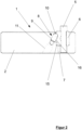
- the figure 1 shows in the perspective representation in the partially exploded representation a milling cutter 1, which is intended in particular to process transparent plastic material, such as acrylic glass.
- the milling cutter 1 in this case comprises a base body 2, which is disk-shaped in the example.
- the base body 2 is in this case fixed to a milling spindle, not shown in detail, with an opening 3 being located in the center of the base body 2, to which the base body 2 can be clamped on the spindle.
- up to four milling tools 4 are embedded in the region of the periphery of the disc-shaped base body 2 and protrude beyond the plane of the base body.
- the milling tools 4 are embodied as cutting pins 5, with some of the milling tools 4 being embodied as rough cutters and the others as finishing cutters, so that surfaces to be machined no longer have to be repolished.
- the cutting pins 5 are clamped in insert holders 6 , the individual insert holder 6 being in an existing one in the base body 2 Receiving pocket 7 is fixed.
- the insert holder 6 in the receiving pocket 7 can be inserted into the receiving pocket 7 under the action of a self-tightening device 8, the insert holder 6 being shown by the device 8 in the inserted state in FIG figure 2 , is fixed.
- the device 8 comprises a clamping bolt 9 mounted in the base body 2 and which locks the insert holder 6 in the receiving pocket 7 in the inserted state, as is shown in FIG figure 2 is shown.
- the clamping bolt 9 which is under a spring effect, is arranged in the base body 2 in an inclined position.
- the clamping bolt 9 has a spherical head 10 which is connected to the spring in the sloping receptacle 11 in relation to a spring which is not shown in detail.
- the spherical head 10 protrudes in this case partially through the wall 12 of the receiving pocket 7, as can be seen from the synopsis of figure 2 and 3 becomes recognizable.
- the insert holder 6 has a guide pocket 14 in its wall 13 for the spherical head 10 of the clamping bolt 9 .
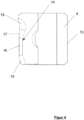
- the guide pocket 14 in its design is here in particular in the figure 3 , but also in the figure 4 shown in more detail, where in particular the insert holder 6 is shown in the sectional view.
- the guide pocket 14 has a beveled alignment surface 15 on the insertion side, which is intended in particular so that when the insert holder 6 is inserted into the receiving pocket 7, the insert holder 6 is first threaded into the opening area of the receiving pocket 7, with the alignment surface 15 then eventually contacting the spherical Head 10 comes into contact, so that then a corresponding alignment of the insert holder 6 relative to the base body 2 is given.
- a clearance area 18 for the head 10 in the clamped state adjoins the clamping surface 17, as can be seen in particular from FIG figure 2 is recognizable.
- slightly laid back clamping surface 17 engages behind the head 10 in the clamped state when the insert holder 6 is pressed into the receiving pocket 7, with the head 10 being guided on the guide surface 16 during the pressing process.
- the wall 12 of the receiving pocket 7 has at least 2 surface strips 19 which are in the figure 1 are only indicated, these surface strips 19 are arranged opposite the clamping bolt 9 .
- the two surface strokes 19 thus form a triangular bracing with the latched clamping bolt 9, which brings about the axial alignment of the insert holder 6 in the receiving pocket.
- a hole 20 corresponding to the clamping bolt 9 is provided in the base body 2 for unlocking, through which a pin-like tool can be inserted, with which the spherical head 10 can then be pushed back in the receptacle 11 for unlocking, in order in this way to be able to remove the insert holder 6 from the receiving pocket 7 by means of a magnet, not shown in detail.
Landscapes
- Engineering & Computer Science (AREA)
- Mechanical Engineering (AREA)
- Milling Processes (AREA)
Description
Die Erfindung betrifft einen Fräser zur Bearbeitung von Kunststoffmaterialien, umfassend einen scheibenförmigen Grundkörper, der an einer Frässpindel festlegbar ist, wobei im Bereich der Peripherie des scheibenförmigen Grundkörpers über die Grundkörperebene hinausragende, als Schneidstifte ausgebildete Fräswerkzeuge eingelassen sind, die in Einsatzhalter verspannt sind und wobei der einzelne Einsatzhalter in einer im Grundkörper vorhandenen Aufnahmetasche fixiert ist.The invention relates to a milling cutter for processing plastic materials, comprising a disk-shaped base body which can be fixed to a milling spindle, with milling tools designed as cutting pins projecting beyond the plane of the base body being embedded in the region of the periphery of the disk-shaped base body, which are clamped in insert holders and wherein the individual insert holder is fixed in a receiving pocket in the base body.
Derartige nach dem Stand der Technik bekannte Fräser eignen sich insbesondere um transparente Kunststoffe zu bearbeiten. Der Fräser besteht vornehmlich aus einem Grundkörper, der als Scheibe ausgebildet ist, wobei in dem Zentrum der Scheibe eine Öffnung vorhanden ist, in der die Frässpindel festgelegt wird um die Scheibe in Rotation zu versetzen. In dieser Scheibe, und zwar insbesondere an der Peripherie der Scheibe, sind stiftartige Fräswerkzeuge eingelassen, die mit Diamanten als Schneidmaterial besetzt sind. In dem Grundkörper sind dabei zwei, drei oder vier sich gegenüber liegende Fräswerkzeuge angeordnet, wobei einige als Vorschneider und andere als Fertigschneider ausgebildet sind. Somit können Oberflächen an einem transparenten Kunststoffblock bearbeitet werden, die gefräst und poliert ausgebildet sind. Die Fräswerkzeuge bestehend aus Halter und Schneidstift selbst sind dabei in dem Grundkörper in Taschen, die als Bohrungen ausgebildet sind, eingelassen und mittels Spannbolzen darin verspannt.Milling cutters of this type, which are known from the prior art, are particularly suitable for processing transparent plastics. The milling cutter consists primarily of a base body which is designed as a disk, with an opening being present in the center of the disk, in which the milling spindle is fixed in order to set the disk in rotation. Pen-like milling tools, which are set with diamonds as the cutting material, are embedded in this disc, in particular on the periphery of the disc. In this case, two, three or four milling tools lying opposite one another are arranged in the base body, with some being designed as rough cutters and others as finishing cutters. In this way, surfaces on a transparent plastic block that are milled and polished can be processed. The milling tools consisting of the holder and the cutting pin itself are let into pockets in the base body, which are designed as bores, and are braced therein by means of clamping bolts.
So ist aus dem Stand der Technik gemäß der
Ein weiterer Fräser zur Bearbeitung ist aus der
Als nächstliegender Stand der Technik wird auf die
Weiterthin wird auf das
Der einzelne Einsatzhalter ist in einer im Grundkörper vorhandenen Aufnahmetasche mittels eines Positionierstiftes fixiert. Bei dieser aus dem Stand der Technik bekannten Ausführungsform sind die Positionierstifte über ihre Schaftlänge in drei Bereiche unterteilt, wobei der obere Bereich zur Positionierung des Einsatzhalters in der Kreistasche, der mittlere Bereich zur Verspannung des Einsatzhalters in dem Grundkörper und der untere Bereich zur Lagerung des Positionierstiftes in dem Grundkörper bestimmt ist. Will man also den Einsatzhalter mit dem Schneidstift wechseln, so bedarf es hier, dass mittels eines Werkzeugs der Positionierstift gelöst wird, sodass dann der Einsatzhalter aus der Aufnahmetasche herausgenommen werden kann.The individual insert holder is fixed in a receiving pocket in the base body by means of a positioning pin. In this embodiment known from the prior art, the positioning pins are divided into three areas along their shaft length, with the upper area for positioning the insert holder in the circular pocket, the middle area for bracing the insert holder in the base body and the lower area for storing the positioning pin is determined in the body. So if you want to change the insert holder with the cutting pin, it is necessary here that the positioning pin is loosened using a tool so that the insert holder can then be removed from the receiving pocket.
Als nachteilig wird es hierbei angesehen, dass aufgrund des Positionierstiftes die Verspannung des Einsatzhalters in der Aufnahmetasche erfolgt. Hierbei bedarf es immer der Zuhilfenahme eines Werkzeugs, um entsprechend die exakte Spannkraft in der Aufnahmetasche vorzuhalten.It is seen as a disadvantage here that the insert holder is braced in the receiving pocket due to the positioning pin. This always requires the use of a tool in order to maintain the exact clamping force in the receiving pocket.
Die nach dem Stand der Technik bekannten Fräser weisen insbesondere den Nachteil auf, dass der als Scheibe ausgebildete Grundkörper einerseits schwer ausfällt, bedingt durch das erforderliche Trägheitsmoment, wobei andererseits auch die Festlegung des Grundkörpers an der Spindel eine aufwändige Justierarbeit erfordert. Es ist daher erforderlich, wenn beispielsweise die Fräswerkzeuge gewechselt oder nachgeschliffen werden müssen, dass dann der gesamte Grundkörper von der Spindel abgenommen werden muss. Aufgrund seines Gewichtes ergeben sich daher Transportprobleme. Ein weiteres Problem ist, dass unterschiedliche Fräswerkzeuge für die einzelnen Arbeitsgänge vorzuhalten sind, die unterschiedliche Einstellparameter haben. Hierzu muss bei jedem Werkzeugwechsel die Werkzeugachse der Maschine nachgestellt werden, was zu Stillstandzeiten in der Produktion führt.The milling cutters known from the prior art have the particular disadvantage that the basic body designed as a disc is heavy on the one hand due to the required moment of inertia, while on the other hand the fixing of the basic body on the spindle also requires complex adjustment work. It is therefore necessary, for example when the milling tools have to be changed or reground, for the entire base body to be removed from the spindle must become. Due to its weight, there are therefore transport problems. Another problem is that different milling tools, which have different setting parameters, have to be kept available for the individual operations. For this purpose, the tool axis of the machine has to be readjusted with each tool change, which leads to downtimes in production.
Der Erfindung stellt sich somit das Problem vor dem aufgezeigten Stand der Technik einen bekannten Fräser derart weiterzubilden, der hinsichtlich des Werkzeugwechsels einfacher, schneller und kostengünstiger zu handhaben ist.The invention thus faces the problem of further developing a known milling cutter in such a way that the tool change is easier, quicker and more economical to handle.
Diese Aufgabe wird erfindungsgemäß durch den Hauptanspruch gelöst, vorteilhafte Ausgestaltungen der Erfindung ergeben sich aus den Unteransprüchen.According to the invention, this object is achieved by the main claim; advantageous refinements of the invention result from the subclaims.
Die mit der Erfindung erreichten Vorteile ergeben sich dadurch, dass bei der erfindungsgemäßen Lösung der Einsatzhalter in die Aufnahmetasche der Scheibe werkzeuglos eingeführt wird, wobei Ausrichtflächen in der Aufnahmetasche zur radialen Ausrichtung des Einsatzhalters vorhanden sind. Zum Einsetzen wird der Einsatzhalter in die Aufnahmetasche eingefädelt, bis dieser über dem Spannbolzen liegt. Erst in dieser Position wird dann der Einsatzhalter in die Aufnahmetasche gedrückt. Dabei drückt die Ausrichtfläche den Spannbolzen nach unten gegen eine Feder und setzt ihn unter Spannung. Die Führungsfläche verhindert, dass der Einsatzhalter sich auf dem Weg nach unten noch einmal radial verdreht. Wenn der Spannbolzen auf die Spannfläche trifft, entspannt sich der Spannbolzen, wobei er über die Spannfläche rutscht. Dabei drückt er den Einsatzhalter gegen die Wand der Aufnahmetasche und den Boden der Aufnahmetasche. Dadurch, dass die Spannfläche einen steileren Winkel hat, als die lineare Bahn des Spannbolzens, erhöht sich die Spannung auf den Einsatzhalter, wenn die Kugel des Spannbolzens über die Spannfläche rutscht.The advantages achieved with the invention result from the fact that, in the solution according to the invention, the insert holder is inserted into the receiving pocket of the disc without tools, with alignment surfaces being present in the receiving pocket for radial alignment of the insert holder. To insert, the insert holder is threaded into the receiving pocket until it lies over the clamping bolt. Only in this position is the insert holder then pressed into the receiving pocket. The alignment surface presses the clamping bolt down against a spring and puts it under tension. The guide surface prevents the insert holder from twisting again radially on the way down. When the clamping bolt hits the clamping surface, the clamping bolt relaxes, sliding over the clamping surface. In doing so, he presses the insert holder against the wall of the receiving pocket and the bottom of the receiving pocket. Because the When the clamping surface has a steeper angle than the linear path of the clamping pin, the tension on the bit holder increases as the ball of the clamping pin slides over the clamping surface.
Durch die Fliehkraft während des Rotierens der Scheibe wird die Spannkraft noch einmal erhöht. Aufgrund dieser Ausbildung wird nun erreicht, dass ein schneller Wechsel des Einsatzhalters vorgenommen werden kann, und zwar dadurch, dass durch Ausbildung des Einsatzhalters einerseits schnell die sog. Einsetzposition gefunden werden kann, wobei andererseits durch einfaches Eindrücken des Einsatzhalters in die Aufnahmetasche eine Fixierung des Einsatzhalters und somit des Schneidstiftes gegeben ist.The clamping force is increased again by the centrifugal force during the rotation of the disc. Due to this design, it is now possible to change the insert holder more quickly, namely in that, on the one hand, the so-called insertion position can be found quickly through the design of the insert holder, and on the other hand, the insert holder can be fixed by simply pressing the insert holder into the receiving pocket and thus the cutting pin is given.
Um insbesondere den Einsatzhalter aus der Aufnahmetasche und wieder von der Scheibe zu entfernen, wird der Spannbolzen durch eine in der Oberseite der Scheibe befindliche Bohrung nach unten gedrückt, wobei der Einsatzhalter dann mithilfe eines Magneten herausgezogen wird. Diese Ausbildung ermöglicht nun, den eingesetzten Einsatzhalter wieder schnell aus dem scheibenförmigen Grundkörper zu entfernen, weil man durch die Bohrung mit einem Werkzeug den Spannbolzen leicht zurückdrücken kann, sodass dann die Freigabe oder Entriegelung erfolgt, um den Einsatzhalter wieder aus der Tasche herauszunehmen.Specifically, to remove the insert holder from the receiving pocket and back from the disc, the clamping bolt is pushed down through a hole in the top of the disc, and the insert holder is then pulled out using a magnet. This design now makes it possible to quickly remove the inserted insert holder from the disc-shaped base body, because the clamping bolt can be easily pushed back through the hole with a tool, so that the release or unlocking then takes place in order to remove the insert holder from the pocket again.
In Weiterbildung ist die Wand der Aufnahmetasche nicht ganz rund gewölbt, sondern sie ist derart ausgebildet, dass sie zwei Flächenstreifen gegenüber dem Spannbolzen aufweist. Der Spannbolzen drückt somit den Einsatzhalter gegen diese Flächen im eingesetzten Zustand. Der Rest der Taschenwand wird nicht berührt. Die beiden Flächen sind so angeordnet, dass sie zusammen mit den Spannbolzen ein Dreieck bilden, um eine stabile Dreipunktlage des Einsatzhalters in der Aufnahmetasche zu bilden. Dadurch bleibt der Einsatzhalter in allen Achsen ausgerichtet.In a further development, the wall of the receiving pocket is not completely curved, but is designed in such a way that it has two surface strips opposite the clamping bolt. The clamping bolt thus presses the insert holder against these surfaces in the inserted state. The rest of the pocket wall is not touched. The two surfaces are arranged in such a way that together with the clamping bolts they form a triangle in order to create a stable three-point position of the insert holder in the receiving pocket. This keeps the insert holder aligned in all axes.
Gemäß der Erfindung wird merkmalsgemäß vorgeschlagen, dass der Einsatzhalter in der Aufnahmetasche unter Wirkung einer selbstspannenden Einrichtung in die Aufnahmetasche einsetzbar ist und wobei der Einsatzhalter durch die Einrichtung im eingesetzten Zustand fixiert ist. Aufgrund dieser Ausbildung wird erreicht, wie bereits beschrieben, dass ein schnell fixierter und ausgerichteter Einsatz bzw. Wechsel des Einsatzhalters in der scheibenförmigen Spindel vorgenommen werden kann.According to the invention, it is proposed that the insert holder can be inserted into the receiving pocket under the action of a self-tightening device and the insert holder is fixed by the device in the inserted state. As already described, this design means that the insert holder can be quickly fixed and aligned or changed in the disk-shaped spindle.
Gemäß der Erfindung umfasst die Einrichtung einen im Grundkörper gelagerten Spannbolzen, der den Einsatzhalter in der Aufnahmetasche im eingesetzten Zustand verrastet. Der Spannbolzen ist in dem Grundkörper unter einer Schräglage angeordnet. In Weiterbildung ragt der Spannbolzen mit seinem kugelförmigen Kopf durch den Wandungsbereich der Aufnahmetasche. Diese Ausbildung gewährleistet einerseits ein einfaches und leichtes Einsetzen, wobei durch die Schräglage auch erreicht wird, dass durch die Fliehkräfte bei der Rotation sich insbesondere die Spannwirkung gegenüber dem Einsatzhalter noch verstärkt wird.According to the invention, the device comprises a clamping bolt which is mounted in the base body and locks the insert holder in the receiving pocket in the inserted state. The clamping bolt is arranged in the base body at an angle. In a further development, the spherical head of the clamping bolt protrudes through the wall area of the receiving pocket. On the one hand, this design ensures simple and easy insertion, with the inclined position also ensuring that the centrifugal forces during rotation in particular increase the clamping effect in relation to the insert holder.
Nach einer besonders vorteilhaften Ausgestaltung der Erfindung weist der Einsatzhalter in seiner Wandung eine Führungstasche für den Kopf des Spannbolzens auf. Die Führungstasche als solches weist einsteckseitig eine angeschrägte Ausrichtfläche für den Einsatzhalter in der Aufnahmetasche auf. Die Ausrichtfläche ermöglicht es, dass bei leichtem Einsetzen des zylinderförmigen Einsatzhalters sofort die entsprechende Position gefunden wird, die für den sich anschließenden Rastvorgang wesentlich ist.According to a particularly advantageous embodiment of the invention, the insert holder has a guide pocket in its wall for the head of the clamping bolt. The guide pocket as such has a beveled alignment surface for the insert holder in the receiving pocket on the insertion side. The alignment surface makes it possible for the corresponding position, which is essential for the subsequent latching process, to be found immediately with easy insertion of the cylindrical insert holder.
Nach einer vorteilhaften Weiterbildung schließt sich an die Ausrichtfläche eine lineare Führungsfläche und eine abgeschrägte Spannfläche für den kugelförmigen Kopf an, wobei die Spannfläche in eine Freifläche für den kugelförmigen Kopf im verspannten Zustand übergeht. Aufgrund dieser Ausbildung wird erreicht, dass insbesondere nachdem die Einfädlung des Einsatzhalters erfolgt ist, quasi eine innen liegende Kulisse für den Kugelkopf des Spannbolzens bereitgestellt wird, der über die Führungstasche hier durch die Lineare und durch die hinterschnittene Rastfläche geführt wird, sodass der Kugelkopf seine Endlage an dem Einsatzhalter leicht und einfach erreichen kann.According to an advantageous development, the alignment surface is followed by a linear guide surface and a beveled clamping surface for the spherical head, with the clamping surface merging into a free surface for the spherical head in the clamped state. Because of this design, it is achieved that, particularly after the insertion of the insert holder has taken place, there is a sort of internal connecting link for the ball head of the clamping bolt is provided, which is guided via the guide pocket here through the linear and through the undercut locking surface, so that the ball head can easily and simply reach its end position on the insert holder.
Nach einer besonders vorteilhaften Ausgestaltung der Erfindung weist die Wandung der Aufnahmetasche wenigstens zwei Flächenstreifen auf, die dem Spannbolzen gegenüberliegend angeordnet sind. Wie bereits schon gesagt, wird dadurch eine radiale Vorgabeausrichtung für den Einsatzhalter vorgesehen, die auf einer Dreipunkteinspannung beruht, sodass dadurch eine exakte Ausrichtung des Einsatzhalters in dem scheibenförmigen Grundkörper gegeben ist.According to a particularly advantageous embodiment of the invention, the wall of the receiving pocket has at least two surface strips which are arranged opposite the clamping bolt. As already mentioned, this provides a default radial orientation for the insert holder, which is based on three-point clamping, so that the insert holder is precisely aligned in the disc-shaped base body.
Um insbesondere den Einsatzhalter schnell und einfach wechseln zu können, ist - wie bereits ebenfalls beschrieben - im Grundkörper zur Entriegelung eine mit dem Spannbolzen korrespondierende Bohrung vorgesehen, die insbesondere im Bereich der Freifläche mündet, wo der Kugelkopf im verrasteten Zustand liegt. Durch ein nadelförmiges Werkzeug kann die Kugel in ihre Führung zurückgedrückt werden, sodass dann der Kugelkopf hier den Verspannungsraum freigibt, um so den Einsatzhalter aus dem scheibenförmigen Grundkörper wieder herauszuholen.In order to be able to change the insert holder quickly and easily, as already described, a hole corresponding to the clamping bolt is provided in the base body for unlocking, which opens out in particular in the area of the free surface where the ball head is in the locked state. The ball can be pushed back into its guide using a needle-shaped tool, so that the ball head releases the bracing space here so that the insert holder can be removed from the disc-shaped base body again.
Ein Ausführungsbeispiel der Erfindung ist in den Zeichnungen rein schematisch dargestellt und wird nachfolgend näher beschrieben. Es zeigt
Figur 1- eine perspektivische Darstellung des scheibenförmigen Grundkörpers mit explosionsartig dargestelltem Einsatzhalter und Schneidstift,
Figur 2- eine geschnittene Ansicht des scheibenförmigen Grundkörpers im Bereich des Einsatzhalters im verspannten Zustand,
- Figur
- eine weitere Darstellung in Teilansicht des scheibenförmigen Grundkörpers mit explosionsartig dargestelltem Spannbolzen und Einsatzhalter und
- Figur 4
- eine geschnittene Ansicht des Einsatzhalters in Alleinstellung.
- figure 1
- a perspective view of the disc-shaped base body with insert holder and cutting pin shown exploded,
- figure 2
- a sectional view of the disc-shaped base body in the area of the insert holder in the clamped state,
- figure
- a further representation in partial view of the disk-shaped base body with the clamping bolt and insert holder shown in an exploded manner and
- figure 4
- a sectional view of the insert holder on its own.
Die
Die Schneidstifte 5 werden dabei in Einsatzhaltern 6 verspannt, wobei der einzelne Einsatzhalter 6 in einer im Grundkörper 2 vorhandenen Aufnahmetasche 7 fixiert wird. Wie insbesondere aus der perspektivischen Darstellung der
Wie aus der Zusammenschau aus der
Wie insbesondere aus der
Es versteht sich somit, dass die leicht zurückgelegte Spannfläche 17 den Kopf 10 im verspannten Zustand hintergreift, wenn der Einsatzhalter 6 in die Aufnahmetasche 7 gedrückt wird, wobei der Kopf 10 an der Führungsfläche 16 während des Drückvorganges geführt wird.It is thus understood that the slightly laid back clamping
In Weiterbildung weist die Wand 12 der Aufnahmetasche 7 wenigstens 2 Flächenstreifen 19 auf, die in der
Wie insbesondere noch aus der
- 11
- Fräsercutter
- 22
- Grundkörperbody
- 33
- Öffnungopening
- 44
- Fräswerkzeugemilling tools
- 55
- Schneidstiftcutting pin
- 66
- Einsatzhalterinsert holder
- 77
- Aufnahmetaschereceiving bag
- 88th
- EinrichtungFurnishings
- 99
- Spannbolzenclamping bolt
- 1010
- kugelförmiger Kopfspherical head
- 1111
- Aufnahme für SpannbolzenMounting for clamping bolts
- 1212
- Wand AufnahmetascheWall recording pocket
- 1313
- Wand Einsatzhalterwall insert holder
- 1414
- Führungstascheguide pocket
- 1515
- angeschrägte Ausrichtflächebeveled alignment surface
- 1616
- lineare Führungsflächelinear guide surface
- 1717
- Spannflächeclamping surface
- 1818
- Freiflächeopen space
- 1919
- Flächenstreifensurface strips
- 2020
- Bohrungdrilling
Claims (7)
- A milling cutter (1) for processing plastic materials, comprising a disc-shaped base body (2) that can be fixed on a milling spindle,wherein milling tools (4), which protrude beyond the base body plane and are realized in the form of cutting pins (5), are embedded in the region of the periphery of the disc-shaped base body (2) and clamped in insert holders (6), andwherein the individual insert holder (6) is fixed in a receptacle pocket (7) provided in the base body (2),characterized inthat the insert holder (6) in the receptacle pocket (7) can be inserted into the receptacle pocket (7) under the effect of a self-clamping device (8),wherein the insert holder (6) is fixed by the device (8) in the inserted state, andwherein the device (8) comprises a spring-loaded clamping pin (9), which is arranged in the base body (2) in an oblique position and snap-locks the insert holder (6) in the receptacle pocket (7) in the inserted state.
- The milling cutter (1) according to claim 1,
characterized in
that the clamping pin (9) protrudes through the wall region (12) of the receptacle pocket (7) with its spherical head (10). - The milling cutter (1) according to claims 1 to 2,
characterized in
that the insert holder (6) has in its wall (13) a guide pocket (14) for the head (10) of the clamping pin (9). - The milling cutter (1) according to claims 1 to 3,
characterized in
that the guide pocket (14) has on the insertion side a beveled alignment surface (15) for the insert holder (6) in the receptacle pocket (7). - The milling cutter (1) according to claims 1 to 4,
characterized in
that the alignment surface (15) is followed by a linear guide surface (16) and a beveled clamping surface (17) for the head (10), wherein the clamping surface (17) transforms into a clearance surface (18) for the head (10) in the clamped state. - The milling cutter (1) according to claims 1 to 5,
characterized in
that the wall (12) of the receptacle pocket (7) has at least two surface strips (19) opposite the clamping pin (9). - The milling cutter (1) according to claims 1 to 6,
characterized in
that a bore (20) corresponding to the clamping pin (9) is provided in the base body (2) for unlocking purposes.
Priority Applications (1)
| Application Number | Priority Date | Filing Date | Title |
|---|---|---|---|
| EP18167631.3A EP3556499B1 (en) | 2018-04-17 | 2018-04-17 | Milling cutter for processing plastic materials |
Applications Claiming Priority (1)
| Application Number | Priority Date | Filing Date | Title |
|---|---|---|---|
| EP18167631.3A EP3556499B1 (en) | 2018-04-17 | 2018-04-17 | Milling cutter for processing plastic materials |
Publications (2)
| Publication Number | Publication Date |
|---|---|
| EP3556499A1 EP3556499A1 (en) | 2019-10-23 |
| EP3556499B1 true EP3556499B1 (en) | 2023-06-14 |
Family
ID=62017178
Family Applications (1)
| Application Number | Title | Priority Date | Filing Date |
|---|---|---|---|
| EP18167631.3A Active EP3556499B1 (en) | 2018-04-17 | 2018-04-17 | Milling cutter for processing plastic materials |
Country Status (1)
| Country | Link |
|---|---|
| EP (1) | EP3556499B1 (en) |
Families Citing this family (1)
| Publication number | Priority date | Publication date | Assignee | Title |
|---|---|---|---|---|
| CN113681838B (en) * | 2021-08-17 | 2022-11-08 | 苏州市百诺塑胶有限责任公司 | Mill and glue mouthful equipment |
Family Cites Families (5)
| Publication number | Priority date | Publication date | Assignee | Title |
|---|---|---|---|---|
| US3378901A (en) * | 1965-10-21 | 1968-04-23 | Goddard & Goddard Company | Milling cutter |
| GB1160425A (en) | 1966-07-20 | 1969-08-06 | Marsh Brothers & Co Ltd | Improvements in or relating to Cutting Tools. |
| DD280272A1 (en) | 1989-03-02 | 1990-07-04 | Karl Marx Stadt Ind Werke | KNIFE HEAD WITH SLIP AND SLICED CUTTING |
| US5054972A (en) * | 1990-05-15 | 1991-10-08 | Cooney Kevin G | Rotary tool for sharpening studs in snowmobile treads |
| DE19947946B4 (en) | 1999-10-06 | 2005-03-17 | Muñoz, Gonzalo Tello | Milling cutters for processing in particular transparent plastic materials |
-
2018
- 2018-04-17 EP EP18167631.3A patent/EP3556499B1/en active Active
Also Published As
| Publication number | Publication date |
|---|---|
| EP3556499A1 (en) | 2019-10-23 |
Similar Documents
| Publication | Publication Date | Title |
|---|---|---|
| DE69825586T3 (en) | CUTTING TOOL ASSEMBLY AND EXCHANGEABLE CUTTING HEAD FOR THIS | |
| DE1627012C3 (en) | Drill head or the like. Tool holder | |
| EP1839788B1 (en) | Burring knife for a deburring tool | |
| CH678834A5 (en) | ||
| DE1298845B (en) | Metal working tool | |
| DE4032176C2 (en) | Slicer | |
| DE2502183B2 (en) | Single-lip bur | |
| DE7528316U (en) | POINT DRILLING TOOL | |
| WO2001028718A1 (en) | Machining tool for high-speed machining | |
| DE4212709C2 (en) | Tool with an interchangeable cutting body with a cylindrical shank for machining, primarily in metalworking | |
| EP3556499B1 (en) | Milling cutter for processing plastic materials | |
| DE1063878B (en) | Shank section undercut in the axial direction, clamped in a holder | |
| DE2234854A1 (en) | TOOL FOR CHIPPING MACHINING, IN PARTICULAR CUTTER HEAD FOR FINISHING WORKPIECES | |
| DE3411557A1 (en) | CUTTING TOOL TO MAKE HOLES | |
| DE102010003569A1 (en) | Method for mounting an internal cylindrical grinding tool | |
| DE102004014842B4 (en) | Tool rotating around its axis | |
| DE102019111986B3 (en) | Method for sharpening a knife that can be inserted into a knife head and knife head with a sharpened knife | |
| DE396068C (en) | Rotating cutting tool with knives inserted in grooves | |
| EP3623089B1 (en) | Cutting tool with a cutting body | |
| CH654772A5 (en) | TOOL FOR DRILLING HOLES IN WORKPIECES. | |
| DE3116326A1 (en) | Brush tool for deburring | |
| DE102024116340A1 (en) | Device for limiting the cutting depth of a cutting tool | |
| DE202024103108U1 (en) | Device for limiting the depth of engagement of a cutting tool | |
| DE1552484C3 (en) | Circle cutting device for the production of round workpiece openings | |
| DE2008789C (en) | Button forming machine |
Legal Events
| Date | Code | Title | Description |
|---|---|---|---|
| PUAI | Public reference made under article 153(3) epc to a published international application that has entered the european phase |
Free format text: ORIGINAL CODE: 0009012 |
|
| STAA | Information on the status of an ep patent application or granted ep patent |
Free format text: STATUS: THE APPLICATION HAS BEEN PUBLISHED |
|
| AK | Designated contracting states |
Kind code of ref document: A1 Designated state(s): AL AT BE BG CH CY CZ DE DK EE ES FI FR GB GR HR HU IE IS IT LI LT LU LV MC MK MT NL NO PL PT RO RS SE SI SK SM TR |
|
| AX | Request for extension of the european patent |
Extension state: BA ME |
|
| STAA | Information on the status of an ep patent application or granted ep patent |
Free format text: STATUS: REQUEST FOR EXAMINATION WAS MADE |
|
| 17P | Request for examination filed |
Effective date: 20200421 |
|
| RBV | Designated contracting states (corrected) |
Designated state(s): AL AT BE BG CH CY CZ DE DK EE ES FI FR GB GR HR HU IE IS IT LI LT LU LV MC MK MT NL NO PL PT RO RS SE SI SK SM TR |
|
| STAA | Information on the status of an ep patent application or granted ep patent |
Free format text: STATUS: EXAMINATION IS IN PROGRESS |
|
| 17Q | First examination report despatched |
Effective date: 20220309 |
|
| GRAP | Despatch of communication of intention to grant a patent |
Free format text: ORIGINAL CODE: EPIDOSNIGR1 |
|
| STAA | Information on the status of an ep patent application or granted ep patent |
Free format text: STATUS: GRANT OF PATENT IS INTENDED |
|
| INTG | Intention to grant announced |
Effective date: 20230125 |
|
| GRAS | Grant fee paid |
Free format text: ORIGINAL CODE: EPIDOSNIGR3 |
|
| GRAA | (expected) grant |
Free format text: ORIGINAL CODE: 0009210 |
|
| STAA | Information on the status of an ep patent application or granted ep patent |
Free format text: STATUS: THE PATENT HAS BEEN GRANTED |
|
| AK | Designated contracting states |
Kind code of ref document: B1 Designated state(s): AL AT BE BG CH CY CZ DE DK EE ES FI FR GB GR HR HU IE IS IT LI LT LU LV MC MK MT NL NO PL PT RO RS SE SI SK SM TR |
|
| REG | Reference to a national code |
Ref country code: CH Ref legal event code: EP |
|
| REG | Reference to a national code |
Ref country code: DE Ref legal event code: R096 Ref document number: 502018012450 Country of ref document: DE |
|
| REG | Reference to a national code |
Ref country code: AT Ref legal event code: REF Ref document number: 1578863 Country of ref document: AT Kind code of ref document: T Effective date: 20230715 |
|
| REG | Reference to a national code |
Ref country code: LT Ref legal event code: MG9D |
|
| REG | Reference to a national code |
Ref country code: NL Ref legal event code: MP Effective date: 20230614 |
|
| PG25 | Lapsed in a contracting state [announced via postgrant information from national office to epo] |
Ref country code: SE Free format text: LAPSE BECAUSE OF FAILURE TO SUBMIT A TRANSLATION OF THE DESCRIPTION OR TO PAY THE FEE WITHIN THE PRESCRIBED TIME-LIMIT Effective date: 20230614 Ref country code: NO Free format text: LAPSE BECAUSE OF FAILURE TO SUBMIT A TRANSLATION OF THE DESCRIPTION OR TO PAY THE FEE WITHIN THE PRESCRIBED TIME-LIMIT Effective date: 20230914 Ref country code: ES Free format text: LAPSE BECAUSE OF FAILURE TO SUBMIT A TRANSLATION OF THE DESCRIPTION OR TO PAY THE FEE WITHIN THE PRESCRIBED TIME-LIMIT Effective date: 20230614 |
|
| PG25 | Lapsed in a contracting state [announced via postgrant information from national office to epo] |
Ref country code: RS Free format text: LAPSE BECAUSE OF FAILURE TO SUBMIT A TRANSLATION OF THE DESCRIPTION OR TO PAY THE FEE WITHIN THE PRESCRIBED TIME-LIMIT Effective date: 20230614 Ref country code: NL Free format text: LAPSE BECAUSE OF FAILURE TO SUBMIT A TRANSLATION OF THE DESCRIPTION OR TO PAY THE FEE WITHIN THE PRESCRIBED TIME-LIMIT Effective date: 20230614 Ref country code: LV Free format text: LAPSE BECAUSE OF FAILURE TO SUBMIT A TRANSLATION OF THE DESCRIPTION OR TO PAY THE FEE WITHIN THE PRESCRIBED TIME-LIMIT Effective date: 20230614 Ref country code: LT Free format text: LAPSE BECAUSE OF FAILURE TO SUBMIT A TRANSLATION OF THE DESCRIPTION OR TO PAY THE FEE WITHIN THE PRESCRIBED TIME-LIMIT Effective date: 20230614 Ref country code: HR Free format text: LAPSE BECAUSE OF FAILURE TO SUBMIT A TRANSLATION OF THE DESCRIPTION OR TO PAY THE FEE WITHIN THE PRESCRIBED TIME-LIMIT Effective date: 20230614 Ref country code: GR Free format text: LAPSE BECAUSE OF FAILURE TO SUBMIT A TRANSLATION OF THE DESCRIPTION OR TO PAY THE FEE WITHIN THE PRESCRIBED TIME-LIMIT Effective date: 20230915 |
|
| PG25 | Lapsed in a contracting state [announced via postgrant information from national office to epo] |
Ref country code: FI Free format text: LAPSE BECAUSE OF FAILURE TO SUBMIT A TRANSLATION OF THE DESCRIPTION OR TO PAY THE FEE WITHIN THE PRESCRIBED TIME-LIMIT Effective date: 20230614 |
|
| PG25 | Lapsed in a contracting state [announced via postgrant information from national office to epo] |
Ref country code: SK Free format text: LAPSE BECAUSE OF FAILURE TO SUBMIT A TRANSLATION OF THE DESCRIPTION OR TO PAY THE FEE WITHIN THE PRESCRIBED TIME-LIMIT Effective date: 20230614 |
|
| PG25 | Lapsed in a contracting state [announced via postgrant information from national office to epo] |
Ref country code: IS Free format text: LAPSE BECAUSE OF FAILURE TO SUBMIT A TRANSLATION OF THE DESCRIPTION OR TO PAY THE FEE WITHIN THE PRESCRIBED TIME-LIMIT Effective date: 20231014 |
|
| PG25 | Lapsed in a contracting state [announced via postgrant information from national office to epo] |
Ref country code: SM Free format text: LAPSE BECAUSE OF FAILURE TO SUBMIT A TRANSLATION OF THE DESCRIPTION OR TO PAY THE FEE WITHIN THE PRESCRIBED TIME-LIMIT Effective date: 20230614 Ref country code: SK Free format text: LAPSE BECAUSE OF FAILURE TO SUBMIT A TRANSLATION OF THE DESCRIPTION OR TO PAY THE FEE WITHIN THE PRESCRIBED TIME-LIMIT Effective date: 20230614 Ref country code: RO Free format text: LAPSE BECAUSE OF FAILURE TO SUBMIT A TRANSLATION OF THE DESCRIPTION OR TO PAY THE FEE WITHIN THE PRESCRIBED TIME-LIMIT Effective date: 20230614 Ref country code: PT Free format text: LAPSE BECAUSE OF FAILURE TO SUBMIT A TRANSLATION OF THE DESCRIPTION OR TO PAY THE FEE WITHIN THE PRESCRIBED TIME-LIMIT Effective date: 20231016 Ref country code: IS Free format text: LAPSE BECAUSE OF FAILURE TO SUBMIT A TRANSLATION OF THE DESCRIPTION OR TO PAY THE FEE WITHIN THE PRESCRIBED TIME-LIMIT Effective date: 20231014 Ref country code: EE Free format text: LAPSE BECAUSE OF FAILURE TO SUBMIT A TRANSLATION OF THE DESCRIPTION OR TO PAY THE FEE WITHIN THE PRESCRIBED TIME-LIMIT Effective date: 20230614 Ref country code: CZ Free format text: LAPSE BECAUSE OF FAILURE TO SUBMIT A TRANSLATION OF THE DESCRIPTION OR TO PAY THE FEE WITHIN THE PRESCRIBED TIME-LIMIT Effective date: 20230614 |
|
| PG25 | Lapsed in a contracting state [announced via postgrant information from national office to epo] |
Ref country code: PL Free format text: LAPSE BECAUSE OF FAILURE TO SUBMIT A TRANSLATION OF THE DESCRIPTION OR TO PAY THE FEE WITHIN THE PRESCRIBED TIME-LIMIT Effective date: 20230614 |
|
| REG | Reference to a national code |
Ref country code: DE Ref legal event code: R097 Ref document number: 502018012450 Country of ref document: DE |
|
| PLBE | No opposition filed within time limit |
Free format text: ORIGINAL CODE: 0009261 |
|
| STAA | Information on the status of an ep patent application or granted ep patent |
Free format text: STATUS: NO OPPOSITION FILED WITHIN TIME LIMIT |
|
| PG25 | Lapsed in a contracting state [announced via postgrant information from national office to epo] |
Ref country code: DK Free format text: LAPSE BECAUSE OF FAILURE TO SUBMIT A TRANSLATION OF THE DESCRIPTION OR TO PAY THE FEE WITHIN THE PRESCRIBED TIME-LIMIT Effective date: 20230614 |
|
| PG25 | Lapsed in a contracting state [announced via postgrant information from national office to epo] |
Ref country code: SI Free format text: LAPSE BECAUSE OF FAILURE TO SUBMIT A TRANSLATION OF THE DESCRIPTION OR TO PAY THE FEE WITHIN THE PRESCRIBED TIME-LIMIT Effective date: 20230614 |
|
| 26N | No opposition filed |
Effective date: 20240315 |
|
| PG25 | Lapsed in a contracting state [announced via postgrant information from national office to epo] |
Ref country code: SI Free format text: LAPSE BECAUSE OF FAILURE TO SUBMIT A TRANSLATION OF THE DESCRIPTION OR TO PAY THE FEE WITHIN THE PRESCRIBED TIME-LIMIT Effective date: 20230614 Ref country code: IT Free format text: LAPSE BECAUSE OF FAILURE TO SUBMIT A TRANSLATION OF THE DESCRIPTION OR TO PAY THE FEE WITHIN THE PRESCRIBED TIME-LIMIT Effective date: 20230614 |
|
| PGFP | Annual fee paid to national office [announced via postgrant information from national office to epo] |
Ref country code: DE Payment date: 20240430 Year of fee payment: 7 |
|
| PG25 | Lapsed in a contracting state [announced via postgrant information from national office to epo] |
Ref country code: BG Free format text: LAPSE BECAUSE OF FAILURE TO SUBMIT A TRANSLATION OF THE DESCRIPTION OR TO PAY THE FEE WITHIN THE PRESCRIBED TIME-LIMIT Effective date: 20230614 |
|
| PG25 | Lapsed in a contracting state [announced via postgrant information from national office to epo] |
Ref country code: MC Free format text: LAPSE BECAUSE OF FAILURE TO SUBMIT A TRANSLATION OF THE DESCRIPTION OR TO PAY THE FEE WITHIN THE PRESCRIBED TIME-LIMIT Effective date: 20230614 |
|
| PG25 | Lapsed in a contracting state [announced via postgrant information from national office to epo] |
Ref country code: MC Free format text: LAPSE BECAUSE OF FAILURE TO SUBMIT A TRANSLATION OF THE DESCRIPTION OR TO PAY THE FEE WITHIN THE PRESCRIBED TIME-LIMIT Effective date: 20230614 Ref country code: BG Free format text: LAPSE BECAUSE OF FAILURE TO SUBMIT A TRANSLATION OF THE DESCRIPTION OR TO PAY THE FEE WITHIN THE PRESCRIBED TIME-LIMIT Effective date: 20230614 |
|
| REG | Reference to a national code |
Ref country code: CH Ref legal event code: PL |
|
| PG25 | Lapsed in a contracting state [announced via postgrant information from national office to epo] |
Ref country code: LU Free format text: LAPSE BECAUSE OF NON-PAYMENT OF DUE FEES Effective date: 20240417 |
|
| GBPC | Gb: european patent ceased through non-payment of renewal fee |
Effective date: 20240417 |
|
| REG | Reference to a national code |
Ref country code: BE Ref legal event code: MM Effective date: 20240430 |
|
| PG25 | Lapsed in a contracting state [announced via postgrant information from national office to epo] |
Ref country code: LU Free format text: LAPSE BECAUSE OF NON-PAYMENT OF DUE FEES Effective date: 20240417 |
|
| PG25 | Lapsed in a contracting state [announced via postgrant information from national office to epo] |
Ref country code: BE Free format text: LAPSE BECAUSE OF NON-PAYMENT OF DUE FEES Effective date: 20240430 |
|
| PG25 | Lapsed in a contracting state [announced via postgrant information from national office to epo] |
Ref country code: GB Free format text: LAPSE BECAUSE OF NON-PAYMENT OF DUE FEES Effective date: 20240417 |
|
| PG25 | Lapsed in a contracting state [announced via postgrant information from national office to epo] |
Ref country code: FR Free format text: LAPSE BECAUSE OF NON-PAYMENT OF DUE FEES Effective date: 20240430 |
|
| PG25 | Lapsed in a contracting state [announced via postgrant information from national office to epo] |
Ref country code: GB Free format text: LAPSE BECAUSE OF NON-PAYMENT OF DUE FEES Effective date: 20240417 Ref country code: FR Free format text: LAPSE BECAUSE OF NON-PAYMENT OF DUE FEES Effective date: 20240430 Ref country code: BE Free format text: LAPSE BECAUSE OF NON-PAYMENT OF DUE FEES Effective date: 20240430 Ref country code: CH Free format text: LAPSE BECAUSE OF NON-PAYMENT OF DUE FEES Effective date: 20240430 |
|
| PG25 | Lapsed in a contracting state [announced via postgrant information from national office to epo] |
Ref country code: IE Free format text: LAPSE BECAUSE OF NON-PAYMENT OF DUE FEES Effective date: 20240417 |
|
| REG | Reference to a national code |
Ref country code: AT Ref legal event code: MM01 Ref document number: 1578863 Country of ref document: AT Kind code of ref document: T Effective date: 20240417 |
|
| PG25 | Lapsed in a contracting state [announced via postgrant information from national office to epo] |
Ref country code: AT Free format text: LAPSE BECAUSE OF NON-PAYMENT OF DUE FEES Effective date: 20240417 |
|
| PG25 | Lapsed in a contracting state [announced via postgrant information from national office to epo] |
Ref country code: CY Free format text: LAPSE BECAUSE OF FAILURE TO SUBMIT A TRANSLATION OF THE DESCRIPTION OR TO PAY THE FEE WITHIN THE PRESCRIBED TIME-LIMIT; INVALID AB INITIO Effective date: 20180417 |
|
| PG25 | Lapsed in a contracting state [announced via postgrant information from national office to epo] |
Ref country code: HU Free format text: LAPSE BECAUSE OF FAILURE TO SUBMIT A TRANSLATION OF THE DESCRIPTION OR TO PAY THE FEE WITHIN THE PRESCRIBED TIME-LIMIT; INVALID AB INITIO Effective date: 20180417 |
|
| REG | Reference to a national code |
Ref country code: DE Ref legal event code: R119 Ref document number: 502018012450 Country of ref document: DE |
|
| PG25 | Lapsed in a contracting state [announced via postgrant information from national office to epo] |
Ref country code: DE Free format text: LAPSE BECAUSE OF NON-PAYMENT OF DUE FEES Effective date: 20251104 |