EP3555367B1 - Rinnensystem sowie verfahren für dessen montage - Google Patents
Rinnensystem sowie verfahren für dessen montage Download PDFInfo
- Publication number
- EP3555367B1 EP3555367B1 EP17822259.2A EP17822259A EP3555367B1 EP 3555367 B1 EP3555367 B1 EP 3555367B1 EP 17822259 A EP17822259 A EP 17822259A EP 3555367 B1 EP3555367 B1 EP 3555367B1
- Authority
- EP
- European Patent Office
- Prior art keywords
- channel
- channel body
- profiles
- support
- profile
- Prior art date
- Legal status (The legal status is an assumption and is not a legal conclusion. Google has not performed a legal analysis and makes no representation as to the accuracy of the status listed.)
- Active
Links
Images

Classifications
-
- E—FIXED CONSTRUCTIONS
- E03—WATER SUPPLY; SEWERAGE
- E03F—SEWERS; CESSPOOLS
- E03F5/00—Sewerage structures
- E03F5/04—Gullies inlets, road sinks, floor drains with or without odour seals or sediment traps
- E03F5/0407—Floor drains for indoor use
- E03F5/0409—Devices for preventing seepage around the floor drain
-
- E—FIXED CONSTRUCTIONS
- E01—CONSTRUCTION OF ROADS, RAILWAYS, OR BRIDGES
- E01C—CONSTRUCTION OF, OR SURFACES FOR, ROADS, SPORTS GROUNDS, OR THE LIKE; MACHINES OR AUXILIARY TOOLS FOR CONSTRUCTION OR REPAIR
- E01C11/00—Details of pavings
- E01C11/22—Gutters; Kerbs ; Surface drainage of streets, roads or like traffic areas
Definitions
- the present application also relates to a method for assembling a gutter system in a floor of a building.
- a “support profile” is understood to mean a component that is inserted into a respective floor.
- the support profile in particular can be formed from aluminum or steel, typically has at least one upstanding leg which laterally delimits the respective floor from the interior space. This means that the floor, for example a screed, is supported against said leg of the support profile or the support profile by means of its upright leg prevents the floor from entering the channel space, for example when it is being introduced.
- the support profiles thus limit the interior space on its two lateral flanks towards the floor.
- Such support profiles can in particular be L-shaped.
- a “U-shaped channel body” is understood to mean a channel body which has at least essentially the shape of a Us. This means that the channel body formed in this way has at least two opposing upright legs and a base lying below. The upright legs do not necessarily have to be oriented vertically, but can also only be inclined with respect to the vertical.
- the U-shape is important insofar as the upright legs of the channel body shaped in this way are suitable for laterally enclosing water guided on the base of the channel body.
- the channel body is suitable for collecting a liquid, in particular water, and diverting it along its longitudinal axis.
- the channel body is advantageously designed symmetrically with respect to a vertical center plane.
- a thickness of the wall or walls of a channel body is typically approximately 3 mm to 10 mm, wherein the channel body can be formed, for example, from an elastomer, preferably a thermoplastic elastomer or thermoelast, or a thermoplastic.
- the channel body is formed from a plastic that has entropy-elastic properties or is more entropy-elastic.
- a “drain” is understood to mean a fluidic guide element, by means of which water collected in the channel body can be diverted from the channel body.
- a horizontal run or any one inclined to the horizontal is also conceivable, which has at least a gradient of at least 0.5%, preferably at least 1.0%, more preferably of at least 1.5%, around a provide a sufficient gradient for the water to be drained off.
- the construction of such a drain is fundamentally independent of the other configuration of a channel system according to the invention.
- a flow connection of a drain to a respective channel body can be formed, for example, by penetrating the channel body, for example from below or from the side.
- the "flanges" described above form, so to speak, an extension of the U-shape in that they adjoin the upper ends of the otherwise U-shaped channel body.
- the flanges typically extend outwardly in an at least substantially horizontal direction.
- a “pressure profile” is basically understood to mean any profile that is suitable for bringing about the described “pressure” of the flange against the surface of the upper end face of the respective associated support profile. It is not absolutely necessary here for the flange of the channel body to be pressed directly onto the associated support profile. It is only essential that the pressure profile exerts a compressive force which is passed through the flange into the surface of the upper end face of the support profile. Ideally, the pressing force of the pressing profile can be anchored in the support profile. For example, it is conceivable that the pressure profile is screwed into the respective support profile by means of a screw connection.
- Channel systems of the type described at the beginning are already known in the prior art. They are used to collect and drain liquids, for example to a drain.
- a corresponding gutter system is typically connected to a slope in the adjacent floor, the gutter system running along a deepest point of the floor.
- a gutter system for draining water is shown.
- This gutter system comprises a gutter body that rests laterally on support profiles.
- the channel body is pressed from its upper side onto the support profiles on both sides by means of pressure profiles.
- the channel system comprises sealing elements that interact with the channel body and indirectly with the support profiles.
- the EP 2 508 685 A1 describes a gutter system.
- the gutter system comprises a gutter body with two oppositely oriented flanges, plates arranged thereon, which in turn form inwardly directed flanges, a flexible layer and pressure profiles.
- the present invention is therefore based on the object of providing a gutter system that is more maintenance-friendly compared to the prior art.
- the underlying object is achieved according to the invention by at least two elongated sealing elements which extend parallel to the support profiles and are each assigned to one of the support profiles.
- the support profiles each interact with one of the sealing elements, the sealing elements typically being designed in the form of strips.
- a respective sealing element is in sealing contact with the surface of the upper end face of the associated support profile.
- the sealing element rests directly on the surface of the support profile, so that a passage of a liquid between the surface of the upper end face and an underside of the sealing element is prevented.
- the sealing elements are each guided to a side of the support profile facing away from the channel body.
- the "left sealing element” is led to a left side of the associated left support profile away from the gutter space, while the “right sealing element” correspondingly to the right side of the associated right support profile away from the gutter space is led.
- a sealing membrane for example, can be brought up to the gutter system on both sides of the gutter system, so that it can interact with the "free ends" of the sealing elements, which are formed on the sides of the gutter system facing away from the gutter body and in this way enable a tight connection of the soil to the gutter system.
- the gutter system according to the invention has many advantages.
- the most important advantage is that a force-transmitting connection between the respective sealing system of the building and the gutter system only takes place with components of the gutter system which are to a certain extent arranged outside the gutter space of the gutter system.
- the tight connection of the sealing system to the gutter system is ensured by means of the sealing elements according to the invention, which, however, are in particular independent of the gutter body. This creates the possibility of removing the channel body from the channel system without loosening or damaging the tight connection of the channel system to the respective sealing system of the building.
- the channel body can be removed from the channel system, a repaired or new channel body inserted and the latter can finally be reinstalled on the channel system by means of at least one pressure profile.
- An intervention, in particular a destructive intervention, with the soil in which the gutter system is installed is not necessary at any time, since the gutter system has created a decoupling of the gutter body from the soil or its sealing system by means of the sealing elements according to the invention.
- the gutter system according to the invention is significantly more maintenance-friendly than that of the prior art.
- an end of a respective sealing element facing away from the channel body is guided along the latter in a downward direction, starting from the upper end face of the associated support profile.
- downward means the direction which is averted from a surface of the floor.
- the sealing element is advantageously guided downwards along at least 20% of a height of the associated support profile, more preferably at least over 50% of the height of the support profile.
- the channel system formed in this way is particularly easy to connect to a sealing system of the respective building, since the sealing elements are led away from the upper face of the support profiles into an area away from the channel space, in which they can ultimately interact particularly easily with a respective sealing system.
- the sealing elements are guided up to a lower, horizontal leg of the support profiles and there on one Surface of the leg can be welded, for example, to a sealing membrane of a sealing system.
- sealing elements are formed from plastic, preferably from a plastic film. Sealing elements of this type can create a sealing connection, especially by pressing onto the surface of the upper end face of the respective associated support profile, and are at the same time flexible, so that connection to a sealing system of the building is particularly easy. Furthermore, such sealing elements can be designed to be particularly elongated in that they can be assembled from a plurality of segments, for example by means of welding.
- such a channel system can be advantageous in which the channel body comprises an end wall on each of its end sides, the end walls being suitable for blocking an end-side exit of water collected in the channel body.
- Such end walls act - roughly comparable to a gutter - as separating elements in order to keep the water collected in the gutter body in the same.
- the same comprises at least two elongated pressure profiles which are each assigned to one of the support profiles.
- the pressure profiles extend parallel to the support profiles, an associated flange of the channel body and / or an associated sealing element preferably being pressed at least indirectly onto the corresponding surface of the upper end face of the associated support profile by means of a pressure profile.
- a pressure profile can be formed, for example, from flat steel which - starting from the surface of the upper end face of a support profile viewed upwards - is placed above the respective flange of the channel body and the associated sealing element on the latter and is finally mounted in such a way that the pressure profile introducing a compressive force into the support profile through the flange and / or the sealing element.
- gutter grates are also referred to as "gutter grates”.
- a gutter cover of this type is used to bridge the inner space in such a way that vertical loads that act in the region of the inner space are directed towards the sides to remove the inner space.
- a channel system must be designed to be traversable by vehicles.
- a channel cover is advantageously designed such that its width exceeds a width of the channel space, so that the channel cover on both sides of the channel space rests at least indirectly on the support profiles, in particular the upper end faces of the support profiles. In this way, forces acting on the gutter cover can be transmitted directly to the support profiles and finally into the ground without the channel body as such being subjected to additional loads. Apart from its own weight and any water that is collected and discharged by means of the channel body, the channel body is consequently free of forces in such a configuration.
- the gutter cover advantageously interacts with the upper end faces of the support profiles, pressure forces being exerted on the flanges and / or the sealing elements by means of the gutter cover in order to produce the sealing engagement with the upper end face of the support profiles.
- a channel system according to the invention which is designed with a channel cover, is particularly advantageous if the channel cover interacts with at least one pressure profile, the pressure profile and the channel cover advantageously connected to a respective associated support profile by means of different connecting means are.
- the connecting means can in particular be formed by screws which are screwed into the respective support profile.
- This embodiment has the particular advantage that the channel cover can in principle be released from the associated support profile independently of the respective pressure profile. This in turn has the significant advantage that the sealing contact between the flange of the channel body and / or the sealing element that is assigned to the respective support profile does not have to be broken when the channel cover is dismantled.
- the dismantling of the channel cover is not accompanied by a dissolution of the compressive force between the upper end face of the support profile and the flange or the sealing element, since this compressive force continues to be provided by means of the pressure profile.
- the channel cover can be exchanged or temporarily dismantled, for example for repair purposes, without further ado and in particular without adversely affecting the channel system.
- a channel system designed in this way is consequently particularly easy to maintain.
- a respective flange of the gutter body and the associated support profile are sealed against one another by means of a tongue and groove system.
- the flange preferably has an elongated spring strip which engages in a complementary elongated groove in the support profile.
- Such a spring strip can preferably have a width in a retaining section which exceeds the width of the elongated groove of the support profile, so that the spring strip is at least partially compressed in the course of the introduction of the spring strip into the elongated groove.
- both a respective flange and a respective sealing element have spring strips which each move into a long groove on the upper end face of the associated support profile.
- the support profiles have two elongated grooves arranged next to one another on their upper end face.
- the channel system according to the invention is also particularly advantageous when the channel body is formed by a plurality of individual channel body segments which are connected to one another in a force-transmitting manner.
- the individual channel body segments are materially connected to one another, in particular welded to one another.
- the channel body segments and consequently the entire channel body are formed from a plastic, in particular a thermoplastic or elastomeric plastic.
- plastics can be connected to one another with a material fit comparatively easily, in the case of a thermoplastic by means of welding and in the case of an elastomeric plastic by means of vulcanization.
- a thermoplastic elastomer or a thermal load is also conceivable.
- the design of the channel body made of plastic is particularly easy in the channel system according to the invention, in particular, if the channel body remains free of payloads that act on the channel system. This can be done particularly easily by means of the above-described configuration of the gutter system with a gutter cover, the width of which exceeds a width of the inner space, so that on Payloads acting on the channel cover are carried directly to the sides of the channel system and have no effect on the channel body.
- the channel body is only loaded with its own weight and any water that is collected and discharged by means of the channel body.
- a sealing plane which is formed between a respective flange of the channel body and / or a respective sealing element and the surface of the upper end face of the associated support profile, is arranged a maximum of 5 cm below a surface of the floor.
- a distance between said sealing plane and the surface of the floor is preferably a maximum of 3 cm, more preferably a maximum of 2 cm.
- the small distance between the sealing plane and the surface of the floor can be constructed in a particularly simple manner in that the support profiles are guided close to the surface of the floor with at least one upright leg, so that the upper end face of a respective support profile is at a small distance from the Surface of the floor is located. Since the flanges and the sealing elements interact with the upper end face of the support profiles, it is understood that consequently the sealing plane is also arranged correspondingly close to the surface of the floor.
- the gutter system can be equipped with two elongated side profiles which are each assigned to one of the support profiles. These side profiles are characterized in that they close the channel system laterally against the adjacent floor, so that the floor is completely decoupled from the channel cover in particular.
- the floor advantageously only comes into direct contact with the support profiles, the sealing elements and the said side profiles.
- the other components of the gutter system are completely decoupled from the floor. This has the particular advantage that those components that are not in contact with the ground can easily be replaced, in particular without having to work on the ground.
- a gutter cover the latter can be dismantled from the gutter system without the floor having to be worked on or damaged as a result. This is delimited laterally from the channel system in particular in an upper area by means of the side profiles.
- the side profiles extend advantageously starting from the surface of the floor downwards or viewed from below as far as a surface of the floor. An upper end face of the side profiles is therefore flush with the floor.
- the side profiles are formed from a flat steel that is laterally connected to an associated support profile, in particular screwed to the support profile.
- the method according to the invention is particularly well suited to producing the channel system according to the invention.
- the channel body is connected to a drain during assembly so that water can be drained from the channel body.
- the drain can have a connection piece which is formed from a thermoplastic or a thermoplastic elastomer. If this also applies to the channel body, the drain can be welded to the channel body and in this way create a tight transition from the channel body to the drain.
- the channel body is composed of a plurality of individual channel body segments.
- the channel body segments are welded to one another. This is particularly advantageous when the channel body segments are formed from a thermoplastic synthetic material or a thermoplastic elastomer.
- the channel body segments are connected to one another by means of vulcanization, the channel body segments being formed from an elastomeric plastic.
- the method designed in this way has the particular advantage that the channel body cannot be manufactured on site on the construction site on which the channel system is to be installed, but rather at an external manufacturing facility.
- the inventive design of the channel body made of plastic offers the essential advantage that the channel body is elastically deformable overall, so that those channel bodies can also be transported whose length significantly exceeds the length of a loading area of a transport vehicle. It goes without saying that most gutter systems have a length that is the length of a loading area of a transport vehicle exceed.
- an elastic plastic is used as the material for the channel body segments and thus the entire channel body, it is now possible according to the invention to elastically deform the channel body, in particular to roll it up or wind it up, to fold it, to bend it or the like in order to shorten an effective length of the channel body overall that it can be transported on a transport vehicle.
- this elastic deformation of the channel body only has to be reversed, for example the channel body must be unwound.
- the channel body is then available as a whole, without the need for subsequent processing at the installation point of the channel system. This both reduces the costs of assembly and avoids sources of error in the course of assembly at the assembly site.
- the method according to the invention can be carried out particularly easily by means of the channel system according to the invention. It has the particular advantage that it can be implemented both in the gutter system and in the soil surrounding the gutter system without any destructive interference. An exchange of the channel body and, if necessary, a channel cover is easily possible since the channel body is decoupled from the floor. As explained above, this is ensured by the action of the sealing elements according to the invention, which ensure a tight connection of the gutter system to a sealing system of the associated structure independently of the channel body.
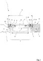
- a first embodiment that is shown in Figure 1 comprises a gutter system 1 according to the invention, which has two elongated support profiles 2 arranged parallel to one another, which delimit a floor 4 laterally against an interior space 3 which extends between the support profiles 2 .
- the support profiles 2, which are formed here from extruded aluminum profiles, have an L-shaped cross section.
- the channel space 3, which extends between the support profiles 2 is bridged by means of a channel body 5.
- the channel system 1 is suitable for collecting liquid, in particular water, which penetrates into the inner space 3 , by means of the channel body 5 and draining it away in a controlled manner.
- the water can then be carried away further, in particular by means of a drain 32 which is fluidically connected to the channel body 5.
- a drain 32 which is fluidically connected to the channel body 5.
- the Channel body 5 is formed here from an elastically deformable, thermoplastic material.
- a wall thickness of the channel body 5 is 5 mm here.
- the gutter body 5 the U-shaped, has on opposite upper lateral ends 9 each have a flange 8, whereby these flanges 8 extending from the ends 9 facing away in a horizontal in about the direction of the channel space 3 sides 13 of the supporting profiles 2 extend.
- the end of the channel body 5 is also closed with end walls, not shown in the figures, which block an end-side exit of the water from the channel body 5.
- the channel body 5 rests with its flanges 8 on the upper end faces 11 of the support profiles 2 .
- the support profiles 2 each have a long groove 21 which is suitable for positively engaging with a complementary spring strip 20 of a respective associated flange 8 of the channel body 5 , so that between an underside of the respective flange 8 and a surface of the upper end faces 11 of the associated support profile 2 a sealing contact is made. A passage of water is therefore prevented in a sealing plane 24, which is located between the underside of the respective flange 8 and the upper end face 11 of the respective support profile 2.
- the spring strips 20 of the flanges 8 each have a width that exceeds a width of the corresponding elongated groove 21 of the associated support profile 2 , so that the spring strips 20 have to be pressed into their respective elongated groove 21, so to speak.
- the spring strips 20 are compressed, as a result of which an increased frictional connection is established between the spring strips 20 and the elongated groove 21 .
- This frictional engagement promotes both a sealing effect of the tongue and groove system and a force transmission between the channel body 5 and the support profiles 2.
- the channel system 1 has sealing elements 12 to the side next to the flanges 8. These are each arranged on the other side of the flanges 8 on the upper end faces 11 of the associated support profiles 2 when viewed from the inner space 3 .
- the sealing elements 12 are likewise connected to the support profiles 2 by means of a tongue and groove system, with spring strips 27 of the sealing elements 12 engaging in elongated grooves 28 of the support profiles 2 .
- the sealing elements 12 are each in sealing contact with the support profiles 2.
- the Andschreibprofile 10 caps are here formed by L-shaped, each with a long leg on a top surface Flanges 8 rest and are guided downwards with a short leg on the side of the support profiles 2.
- the pressure profiles 10 are each connected by means of screws 18 to the support profiles 2 in a force-transmitting manner. By means of these screw connections, the pressure profiles 10 exert a compressive force on the respectively associated flange 8 and the respectively associated sealing element 12 , whereby the sealing contact of both the flange 8 and the sealing element 12 with the upper end face 11 of the respective support profile 2 is ensured.
- the sealing elements 12 are guided downwards under the associated pressure profile in FIG. 10 along the associated support profile 2 in a direction facing away from an upper side 15 of the base 4 , one end 14 of a respective sealing element 12 protruding under the associated pressure profile 10 .
- This end 14 of the sealing element 12 is suitable for being connected to a subsequent sealing system of the structure in which the gutter system 1 is inserted. This ensures that a liquid that accumulates on the floor 4 of the structure does not penetrate the structure at an unintended point, but is reliably conducted to the gutter system 1 , from where it can be drained off by means of the gutter body 5 .
- the sealing element 12 extends along approximately 20% of a height 16 of the associated support profile 2.
- connection of the gutter system 1 according to the invention to a sealing system of the building takes place through the action of the sealing elements 12 completely independently of the gutter body 5 Figure 1 It is easily conceivable to detach the pressure profiles 10 of the gutter system 1 from the respectively associated support profile 2 and then to remove the gutter body 5 in an upward direction.
- the connection of the gutter system 1 is ensured according to the invention by means of the sealing elements 12 , which are independent of the gutter body 5 in their in Figure 1 can remain in the position shown. In this way, with the gutter system 1 according to the invention, it is possible to maintain the gutter body 5 in a particularly simple manner.
- the channel system 1 shown has a channel cover 17 which bridges the inner space 3.
- the channel cover 17 has a width 22 that exceeds a width 23 of the channel body 5 , so that loads that act on the channel cover 17 can be removed on both sides of the channel system 1 without impacting the channel body 5 .
- the channel cover 17 rests indirectly, that is to say with the interposition of the pressure profiles 10 as well as the flanges 8 and the sealing elements 12, on the upper end faces 11 of the support profiles 2 .
- the channel cover 11 is in turn connected by means of screws 19 to the support profiles 2 in a force-transmitting manner.
- a channel cover 17 acts as a pressure profile for both the flanges 8 and the sealing elements 12 .
- the pressure profiles 10 described are used to press the flanges 8 and the sealing elements 12 .
- the latter has the advantage that in the gutter system 1 it is particularly easy to dismantle the gutter cover 17 from the rest of the gutter system 1 without impairing the sealing engagement between the flanges 8 or the sealing elements 12 and the associated support profiles 2. With regard to the ease of maintenance of the gutter system 1 , this is advantageous.
- the channel cover 17 is equipped with reinforcing profiles 26 along its longitudinal axis, which increase the load-bearing capacity of the channel cover 17 .
- the channel system 1 shown also has two elongated side profiles 25 which each correspond to one of the support profiles 2.
- the side profiles 25 are each formed by flat steel which is mounted on the channel system 1 in an upright position.
- each of the side profiles 25 is connected to the short leg of the associated pressure profile 10 .
- the side profiles 25 are arranged on the channel system 1 in such a way that the upper end faces 35 of the side profiles 25 are flush with the surface 15 of the floor 4 .
- This has the particular effect that the base 4 is decoupled from the other components of the gutter system 1, namely in particular by the channel cover 17 and the channel body 5.
- This in turn has the particular advantage that both the channel cover 17 and the channel body 5 of the
- the gutter system 1 can be dismantled without any special intervention in the floor 4 being necessary. In particular, the floor 4 does not have to be processed.
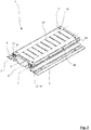
- the gutter system 1 according to Figure 1 is in Figure 2 shown again in an isometric view.
- the channel body 5 extends with its longitudinal axis 6 parallel to the longitudinal axes 7 of the support profiles 2 .
- the support profiles 2 are connected to the pressure profiles 10 by means of screws 36 .
- the channel cover 17 has a plurality of recesses 29 , which are designed here in the form of elongated slots. These recesses 29 allow a liquid to pass from an upper side of the channel cover 17 into the channel body 5.
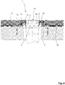
- the gutter system 1 according to the invention according to Figure 1 is also in Figure 3 shown in a state mounted on a building.
- other sealing elements 12 have been used here, the ends 4 of which, facing away from the interior space 3 , extend to a lower leg 37 of the support profiles 2 and rest there.
- the support profiles 2 are anchored in a reinforced concrete ceiling 31 by means of connecting means 33, which are designed here in the form of threaded bolts.
- the associated sealing element 12 is sealingly connected to a bitumen sheet 30 of the structure, so that the sealing connection of the gutter system 1 to the sealing system of the structure is established.
- the "long" sealing elements 12 according to FIG Figure 3 can be used in particular when the sealing system of the structure is guided at a comparatively large distance from the surface 15 of the floor 4.
- the sealing system of the structure consists of bitumen sheets 30 which are guided on a surface of the reinforced concrete ceiling 31 and are covered with a floor 4.
- the use of "short" sealing elements 12, as in the exemplary embodiment according to FIG Figure 1 are shown, however, are used in particular when the sealing system of the structure is guided at a small distance below the surface 15 of the floor 4.
- such short sealing elements 12 can be connected to an upper sealing layer made of an epoxy resin.
- the gutter system 1 according to Figure 3 is shown in a cross section which intersects a vertical drain 32 of the structure.
- a vertical drain 32 of the structure By means of the channel body 5 and collected derived water is discharged from the trough body 5 by means of the process 32nd
- FIG Figure 4 An alternative embodiment of the gutter system 1, which is shown in FIG Figure 4 is shown is essentially identical to that embodiment according to FIG Figure 3 , but differs in the scope of the gutter cover 17.
- the channel cover 17 is formed by a body which rests indirectly on the upper end faces 11 of the support profiles 2 by means of lateral flanges.
- the channel cover 17 does not have such flanges.
- the pressure profiles 10 of the channel system are shown in FIG Figure 4 designed in such a way that they hold ready in the region of the channel 3 support surfaces 38 on which the channel cover 17 can be placed.
- the gutter cover 17 is located in the gutter system 1 according to FIG Figure 4 to a certain extent only loosely on the bearing surfaces 38 of the pressure profiles 10 .
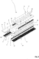
- FIG. 1 Another embodiment of a gutter system according to the invention is an in Figure 5 shown in an exploded view.
- the channel system 1 according to FIG. 1 is purely by way of example Figure 5 provided with different sealing elements 12 , so that the different configuration of sealing elements 12 is understandable.
- the sealing element 12 that in Figure 5 is arranged on a left side of the channel space 3 , made so long that the end 14 of the sealing element 12 extends up to the lower leg 37 of the associated support profile 2 and beyond.
- Such a sealing element 12 is particularly well suited for connection to a “deep-seated” sealing system of a building, as in the example of FIG Figure 3 shown.
- the gutter system 1 On the in Figure 5 On the right side of the inner space 3 , the gutter system 1 is provided with a short sealing element 12 , the end 14 of which is already close below an in Figure 5 surface 15, not shown, of the bottom 4 ends.
- a sealing element 12 can be connected particularly well to a structure belonging to a sealing system arranged close to the surface.
- the sealing elements 12 are designed to be elongated, so that they are particularly suitable for covering butt joints 34 of the support profiles 2. It goes without saying that such butt joints 34 form a potential leak in the gutter system 1 . By covering these butt joints 34 by means of the sealing elements 12 , the butt joints 34 are reliably sealed. Basically regardless of the rest of the configuration of the gutter system 1 according to the invention, it can be of particular advantage if the sealing elements 12 are made of a plastic, in particular a thermoplastic or elastomeric plastic, so that individual segments of sealing elements 12 can be connected to one another particularly easily. Ideally, the sealing elements 12 are already manufactured to a desired length away from an assembly site of the channel system 1 , so that only the sealing elements 12 have to be brought into engagement with the support profiles 2 at the assembly site.
Landscapes
- Engineering & Computer Science (AREA)
- Architecture (AREA)
- Civil Engineering (AREA)
- Structural Engineering (AREA)
- Health & Medical Sciences (AREA)
- Life Sciences & Earth Sciences (AREA)
- Hydrology & Water Resources (AREA)
- Public Health (AREA)
- Water Supply & Treatment (AREA)
- Sewage (AREA)
Priority Applications (1)
| Application Number | Priority Date | Filing Date | Title |
|---|---|---|---|
| PL17822259T PL3555367T3 (pl) | 2016-12-19 | 2017-12-19 | Układ rynnowy i sposób jego montażu |
Applications Claiming Priority (2)
| Application Number | Priority Date | Filing Date | Title |
|---|---|---|---|
| DE102016124836.3A DE102016124836A1 (de) | 2016-12-19 | 2016-12-19 | Rinnensystem sowie Verfahren für dessen Montage |
| PCT/EP2017/083459 WO2018114898A1 (de) | 2016-12-19 | 2017-12-19 | Rinnensystem sowie verfahren für dessen montage |
Publications (2)
| Publication Number | Publication Date |
|---|---|
| EP3555367A1 EP3555367A1 (de) | 2019-10-23 |
| EP3555367B1 true EP3555367B1 (de) | 2021-09-29 |
Family
ID=60857068
Family Applications (1)
| Application Number | Title | Priority Date | Filing Date |
|---|---|---|---|
| EP17822259.2A Active EP3555367B1 (de) | 2016-12-19 | 2017-12-19 | Rinnensystem sowie verfahren für dessen montage |
Country Status (4)
| Country | Link |
|---|---|
| EP (1) | EP3555367B1 (pl) |
| DE (1) | DE102016124836A1 (pl) |
| PL (1) | PL3555367T3 (pl) |
| WO (1) | WO2018114898A1 (pl) |
Families Citing this family (1)
| Publication number | Priority date | Publication date | Assignee | Title |
|---|---|---|---|---|
| RU2699170C1 (ru) * | 2018-11-09 | 2019-09-03 | Никита Михайлович Лапшин | Канал для отведения жидкости |
Family Cites Families (8)
| Publication number | Priority date | Publication date | Assignee | Title |
|---|---|---|---|---|
| DE3020035C2 (de) * | 1980-05-24 | 1985-01-10 | Migua Hammerschmidt GmbH, 5628 Heiligenhaus | Bewegungsfugen-Dichtungsvorrichtung |
| DE3740470C2 (de) * | 1987-11-28 | 1998-07-02 | Hauraton Betonwaren | Entwässerungsrinne und damit aufgebautes Rinnensystem |
| DE8910414U1 (de) * | 1989-08-31 | 1989-10-26 | Passavant-Werke AG, 6209 Aarbergen | Rinne zur Abführung von Oberflächenwasser |
| US6460214B1 (en) * | 2001-03-27 | 2002-10-08 | Ming-Huang Chang | Vibration resistive instant responding roadway or bridge expansion joint and construction method of the same |
| SE0602178L (sv) * | 2006-10-17 | 2008-04-18 | Purus Ab | Förfarande och anordning för positionering och fixering av avloppsränna |
| KR20120050831A (ko) * | 2010-11-11 | 2012-05-21 | 박황 | 배수트렌치 구조 |
| NL2006553C2 (nl) * | 2011-04-06 | 2012-10-09 | Easy Sanitairy Solutions Bv | Klemconstructie voor afvoer. |
| DE102011119705A1 (de) * | 2011-11-29 | 2013-05-29 | Dieter Preissing | Ablaufeinheit |
-
2016
- 2016-12-19 DE DE102016124836.3A patent/DE102016124836A1/de not_active Ceased
-
2017
- 2017-12-19 PL PL17822259T patent/PL3555367T3/pl unknown
- 2017-12-19 EP EP17822259.2A patent/EP3555367B1/de active Active
- 2017-12-19 WO PCT/EP2017/083459 patent/WO2018114898A1/de not_active Ceased
Also Published As
| Publication number | Publication date |
|---|---|
| WO2018114898A1 (de) | 2018-06-28 |
| PL3555367T3 (pl) | 2022-02-07 |
| DE102016124836A1 (de) | 2018-06-21 |
| EP3555367A1 (de) | 2019-10-23 |
Similar Documents
| Publication | Publication Date | Title |
|---|---|---|
| DE3222409C2 (pl) | ||
| EP2925932B1 (de) | Dehnfugen-überbrückungsvorrichtung | |
| EP2098662B1 (de) | Montage- und Reparaturgrube sowie System zur Entsorgung von Abwasser im Bereich von Montagegruben | |
| EP2851477A1 (de) | Entwässerungsrinne | |
| EP1340853A1 (de) | Dichtungsvorrichtung für eine Bewegungsfuge | |
| EP3555367B1 (de) | Rinnensystem sowie verfahren für dessen montage | |
| EP0250612A1 (de) | Gerüstboden für ein Schnellbaugerüst | |
| DE8916127U1 (de) | Vorrichtung zur federnden Einspannung von Traversen einer Fahrbahnüberbrückungskonstruktion | |
| DE202008016244U1 (de) | Stahl-Beton-Decke | |
| EP3436638B1 (de) | Übergangskonstruktion zur überbrückung einer bauwerksfuge | |
| EP2940225A1 (de) | Vorrichtung zum Überbrücken einer Dehnfuge | |
| EP3527734B1 (de) | Entwässerungsrinne mit aufsteckzarge | |
| WO2013189491A1 (de) | Schalungsformanordnung | |
| EP3321545B1 (de) | Dichtungsprofil, und damit ausgestattete dichtungsanordnung | |
| DE102016208490A1 (de) | Schalungselement zum Ausbilden von Dehnungs- oder Pressfugen in Betonbauteilen | |
| DE202012104788U1 (de) | Schalungselement für den Fußbodenbau | |
| DE102012112023B4 (de) | Fußbodenbauschalungselement | |
| EP1719848A2 (de) | Entwässerungsrinne aus Rinnenelementen | |
| DE102012104073B4 (de) | Extrusionswerkzeug zum Extrusionsblasformen von Kunststoffbehältern | |
| DE202008013674U1 (de) | Gerüstboden mit separatem Plattenrand-Einfassungsprofil | |
| DE10100713A1 (de) | Dichtmittel und Verfahren zum Verschließen einer Fuge | |
| EP2692951B1 (de) | Schachtabdeckung und Verfahren zur Herstellung einer Schachtabdeckung | |
| DE3506974C2 (pl) | ||
| EP0622494A2 (de) | Fahrbahnübergang | |
| DE2634992A1 (de) | Schutzhuelle und verfahren zu deren nachtraeglichen anbringen an den innenwandungsflaechen oder teilen dieser von waagerechten oder senkrechten rohrfoermigen oder kanalartigen bauwerken, insbesondere betonrohren, zum zwecke der abdichtung und/oder ausbildung eines innenflaechenschutzes |
Legal Events
| Date | Code | Title | Description |
|---|---|---|---|
| STAA | Information on the status of an ep patent application or granted ep patent |
Free format text: STATUS: UNKNOWN |
|
| STAA | Information on the status of an ep patent application or granted ep patent |
Free format text: STATUS: THE INTERNATIONAL PUBLICATION HAS BEEN MADE |
|
| PUAI | Public reference made under article 153(3) epc to a published international application that has entered the european phase |
Free format text: ORIGINAL CODE: 0009012 |
|
| STAA | Information on the status of an ep patent application or granted ep patent |
Free format text: STATUS: REQUEST FOR EXAMINATION WAS MADE |
|
| 17P | Request for examination filed |
Effective date: 20190517 |
|
| AK | Designated contracting states |
Kind code of ref document: A1 Designated state(s): AL AT BE BG CH CY CZ DE DK EE ES FI FR GB GR HR HU IE IS IT LI LT LU LV MC MK MT NL NO PL PT RO RS SE SI SK SM TR |
|
| AX | Request for extension of the european patent |
Extension state: BA ME |
|
| DAV | Request for validation of the european patent (deleted) | ||
| DAX | Request for extension of the european patent (deleted) | ||
| STAA | Information on the status of an ep patent application or granted ep patent |
Free format text: STATUS: EXAMINATION IS IN PROGRESS |
|
| 17Q | First examination report despatched |
Effective date: 20201026 |
|
| GRAP | Despatch of communication of intention to grant a patent |
Free format text: ORIGINAL CODE: EPIDOSNIGR1 |
|
| STAA | Information on the status of an ep patent application or granted ep patent |
Free format text: STATUS: GRANT OF PATENT IS INTENDED |
|
| INTG | Intention to grant announced |
Effective date: 20210525 |
|
| GRAS | Grant fee paid |
Free format text: ORIGINAL CODE: EPIDOSNIGR3 |
|
| GRAA | (expected) grant |
Free format text: ORIGINAL CODE: 0009210 |
|
| STAA | Information on the status of an ep patent application or granted ep patent |
Free format text: STATUS: THE PATENT HAS BEEN GRANTED |
|
| AK | Designated contracting states |
Kind code of ref document: B1 Designated state(s): AL AT BE BG CH CY CZ DE DK EE ES FI FR GB GR HR HU IE IS IT LI LT LU LV MC MK MT NL NO PL PT RO RS SE SI SK SM TR |
|
| REG | Reference to a national code |
Ref country code: GB Ref legal event code: FG4D Free format text: NOT ENGLISH |
|
| REG | Reference to a national code |
Ref country code: DE Ref legal event code: R096 Ref document number: 502017011624 Country of ref document: DE |
|
| REG | Reference to a national code |
Ref country code: CH Ref legal event code: EP Ref country code: AT Ref legal event code: REF Ref document number: 1434289 Country of ref document: AT Kind code of ref document: T Effective date: 20211015 |
|
| REG | Reference to a national code |
Ref country code: IE Ref legal event code: FG4D Free format text: LANGUAGE OF EP DOCUMENT: GERMAN |
|
| REG | Reference to a national code |
Ref country code: LT Ref legal event code: MG9D |
|
| PG25 | Lapsed in a contracting state [announced via postgrant information from national office to epo] |
Ref country code: SE Free format text: LAPSE BECAUSE OF FAILURE TO SUBMIT A TRANSLATION OF THE DESCRIPTION OR TO PAY THE FEE WITHIN THE PRESCRIBED TIME-LIMIT Effective date: 20210929 Ref country code: RS Free format text: LAPSE BECAUSE OF FAILURE TO SUBMIT A TRANSLATION OF THE DESCRIPTION OR TO PAY THE FEE WITHIN THE PRESCRIBED TIME-LIMIT Effective date: 20210929 Ref country code: HR Free format text: LAPSE BECAUSE OF FAILURE TO SUBMIT A TRANSLATION OF THE DESCRIPTION OR TO PAY THE FEE WITHIN THE PRESCRIBED TIME-LIMIT Effective date: 20210929 Ref country code: FI Free format text: LAPSE BECAUSE OF FAILURE TO SUBMIT A TRANSLATION OF THE DESCRIPTION OR TO PAY THE FEE WITHIN THE PRESCRIBED TIME-LIMIT Effective date: 20210929 Ref country code: NO Free format text: LAPSE BECAUSE OF FAILURE TO SUBMIT A TRANSLATION OF THE DESCRIPTION OR TO PAY THE FEE WITHIN THE PRESCRIBED TIME-LIMIT Effective date: 20211229 Ref country code: LT Free format text: LAPSE BECAUSE OF FAILURE TO SUBMIT A TRANSLATION OF THE DESCRIPTION OR TO PAY THE FEE WITHIN THE PRESCRIBED TIME-LIMIT Effective date: 20210929 Ref country code: BG Free format text: LAPSE BECAUSE OF FAILURE TO SUBMIT A TRANSLATION OF THE DESCRIPTION OR TO PAY THE FEE WITHIN THE PRESCRIBED TIME-LIMIT Effective date: 20211229 |
|
| REG | Reference to a national code |
Ref country code: NL Ref legal event code: MP Effective date: 20210929 |
|
| REG | Reference to a national code |
Ref country code: DE Ref legal event code: R082 Ref document number: 502017011624 Country of ref document: DE Representative=s name: BAUER WAGNER PELLENGAHR SROKA PATENT- & RECHTS, DE Ref country code: DE Ref legal event code: R082 Ref document number: 502017011624 Country of ref document: DE Representative=s name: BAUER PSU PARTG MBB, DE |
|
| PG25 | Lapsed in a contracting state [announced via postgrant information from national office to epo] |
Ref country code: LV Free format text: LAPSE BECAUSE OF FAILURE TO SUBMIT A TRANSLATION OF THE DESCRIPTION OR TO PAY THE FEE WITHIN THE PRESCRIBED TIME-LIMIT Effective date: 20210929 Ref country code: GR Free format text: LAPSE BECAUSE OF FAILURE TO SUBMIT A TRANSLATION OF THE DESCRIPTION OR TO PAY THE FEE WITHIN THE PRESCRIBED TIME-LIMIT Effective date: 20211230 |
|
| PG25 | Lapsed in a contracting state [announced via postgrant information from national office to epo] |
Ref country code: IS Free format text: LAPSE BECAUSE OF FAILURE TO SUBMIT A TRANSLATION OF THE DESCRIPTION OR TO PAY THE FEE WITHIN THE PRESCRIBED TIME-LIMIT Effective date: 20220129 Ref country code: SK Free format text: LAPSE BECAUSE OF FAILURE TO SUBMIT A TRANSLATION OF THE DESCRIPTION OR TO PAY THE FEE WITHIN THE PRESCRIBED TIME-LIMIT Effective date: 20210929 Ref country code: RO Free format text: LAPSE BECAUSE OF FAILURE TO SUBMIT A TRANSLATION OF THE DESCRIPTION OR TO PAY THE FEE WITHIN THE PRESCRIBED TIME-LIMIT Effective date: 20210929 Ref country code: PT Free format text: LAPSE BECAUSE OF FAILURE TO SUBMIT A TRANSLATION OF THE DESCRIPTION OR TO PAY THE FEE WITHIN THE PRESCRIBED TIME-LIMIT Effective date: 20220131 Ref country code: NL Free format text: LAPSE BECAUSE OF FAILURE TO SUBMIT A TRANSLATION OF THE DESCRIPTION OR TO PAY THE FEE WITHIN THE PRESCRIBED TIME-LIMIT Effective date: 20210929 Ref country code: ES Free format text: LAPSE BECAUSE OF FAILURE TO SUBMIT A TRANSLATION OF THE DESCRIPTION OR TO PAY THE FEE WITHIN THE PRESCRIBED TIME-LIMIT Effective date: 20210929 Ref country code: EE Free format text: LAPSE BECAUSE OF FAILURE TO SUBMIT A TRANSLATION OF THE DESCRIPTION OR TO PAY THE FEE WITHIN THE PRESCRIBED TIME-LIMIT Effective date: 20210929 Ref country code: CZ Free format text: LAPSE BECAUSE OF FAILURE TO SUBMIT A TRANSLATION OF THE DESCRIPTION OR TO PAY THE FEE WITHIN THE PRESCRIBED TIME-LIMIT Effective date: 20210929 Ref country code: AL Free format text: LAPSE BECAUSE OF FAILURE TO SUBMIT A TRANSLATION OF THE DESCRIPTION OR TO PAY THE FEE WITHIN THE PRESCRIBED TIME-LIMIT Effective date: 20210929 |
|
| REG | Reference to a national code |
Ref country code: DE Ref legal event code: R097 Ref document number: 502017011624 Country of ref document: DE |
|
| PG25 | Lapsed in a contracting state [announced via postgrant information from national office to epo] |
Ref country code: MC Free format text: LAPSE BECAUSE OF FAILURE TO SUBMIT A TRANSLATION OF THE DESCRIPTION OR TO PAY THE FEE WITHIN THE PRESCRIBED TIME-LIMIT Effective date: 20210929 Ref country code: DK Free format text: LAPSE BECAUSE OF FAILURE TO SUBMIT A TRANSLATION OF THE DESCRIPTION OR TO PAY THE FEE WITHIN THE PRESCRIBED TIME-LIMIT Effective date: 20210929 |
|
| REG | Reference to a national code |
Ref country code: CH Ref legal event code: PL |
|
| PLBE | No opposition filed within time limit |
Free format text: ORIGINAL CODE: 0009261 |
|
| STAA | Information on the status of an ep patent application or granted ep patent |
Free format text: STATUS: NO OPPOSITION FILED WITHIN TIME LIMIT |
|
| GBPC | Gb: european patent ceased through non-payment of renewal fee |
Effective date: 20211229 |
|
| 26N | No opposition filed |
Effective date: 20220630 |
|
| PG25 | Lapsed in a contracting state [announced via postgrant information from national office to epo] |
Ref country code: IE Free format text: LAPSE BECAUSE OF NON-PAYMENT OF DUE FEES Effective date: 20211219 Ref country code: GB Free format text: LAPSE BECAUSE OF NON-PAYMENT OF DUE FEES Effective date: 20211229 |
|
| PG25 | Lapsed in a contracting state [announced via postgrant information from national office to epo] |
Ref country code: SI Free format text: LAPSE BECAUSE OF FAILURE TO SUBMIT A TRANSLATION OF THE DESCRIPTION OR TO PAY THE FEE WITHIN THE PRESCRIBED TIME-LIMIT Effective date: 20210929 |
|
| PG25 | Lapsed in a contracting state [announced via postgrant information from national office to epo] |
Ref country code: LI Free format text: LAPSE BECAUSE OF NON-PAYMENT OF DUE FEES Effective date: 20211231 Ref country code: CH Free format text: LAPSE BECAUSE OF NON-PAYMENT OF DUE FEES Effective date: 20211231 |
|
| PG25 | Lapsed in a contracting state [announced via postgrant information from national office to epo] |
Ref country code: IT Free format text: LAPSE BECAUSE OF FAILURE TO SUBMIT A TRANSLATION OF THE DESCRIPTION OR TO PAY THE FEE WITHIN THE PRESCRIBED TIME-LIMIT Effective date: 20210929 |
|
| P01 | Opt-out of the competence of the unified patent court (upc) registered |
Effective date: 20230521 |
|
| PG25 | Lapsed in a contracting state [announced via postgrant information from national office to epo] |
Ref country code: CY Free format text: LAPSE BECAUSE OF FAILURE TO SUBMIT A TRANSLATION OF THE DESCRIPTION OR TO PAY THE FEE WITHIN THE PRESCRIBED TIME-LIMIT Effective date: 20210929 |
|
| PG25 | Lapsed in a contracting state [announced via postgrant information from national office to epo] |
Ref country code: SM Free format text: LAPSE BECAUSE OF FAILURE TO SUBMIT A TRANSLATION OF THE DESCRIPTION OR TO PAY THE FEE WITHIN THE PRESCRIBED TIME-LIMIT Effective date: 20210929 Ref country code: HU Free format text: LAPSE BECAUSE OF FAILURE TO SUBMIT A TRANSLATION OF THE DESCRIPTION OR TO PAY THE FEE WITHIN THE PRESCRIBED TIME-LIMIT; INVALID AB INITIO Effective date: 20171219 |
|
| PG25 | Lapsed in a contracting state [announced via postgrant information from national office to epo] |
Ref country code: MK Free format text: LAPSE BECAUSE OF FAILURE TO SUBMIT A TRANSLATION OF THE DESCRIPTION OR TO PAY THE FEE WITHIN THE PRESCRIBED TIME-LIMIT Effective date: 20210929 |
|
| PG25 | Lapsed in a contracting state [announced via postgrant information from national office to epo] |
Ref country code: MT Free format text: LAPSE BECAUSE OF FAILURE TO SUBMIT A TRANSLATION OF THE DESCRIPTION OR TO PAY THE FEE WITHIN THE PRESCRIBED TIME-LIMIT Effective date: 20210929 |
|
| PGFP | Annual fee paid to national office [announced via postgrant information from national office to epo] |
Ref country code: AT Payment date: 20251218 Year of fee payment: 9 |
|
| PGFP | Annual fee paid to national office [announced via postgrant information from national office to epo] |
Ref country code: LU Payment date: 20251222 Year of fee payment: 9 Ref country code: FR Payment date: 20251223 Year of fee payment: 9 |
|
| PGFP | Annual fee paid to national office [announced via postgrant information from national office to epo] |
Ref country code: TR Payment date: 20251201 Year of fee payment: 9 |
|
| PGFP | Annual fee paid to national office [announced via postgrant information from national office to epo] |
Ref country code: PL Payment date: 20251125 Year of fee payment: 9 |
|
| PGFP | Annual fee paid to national office [announced via postgrant information from national office to epo] |
Ref country code: DE Payment date: 20251231 Year of fee payment: 9 |
|
| PGFP | Annual fee paid to national office [announced via postgrant information from national office to epo] |
Ref country code: BE Payment date: 20260109 Year of fee payment: 9 |