EP3552945B1 - Véhicule sous-marin doté d'un volet pouvant être bloqué - Google Patents
Véhicule sous-marin doté d'un volet pouvant être bloqué Download PDFInfo
- Publication number
- EP3552945B1 EP3552945B1 EP19166966.2A EP19166966A EP3552945B1 EP 3552945 B1 EP3552945 B1 EP 3552945B1 EP 19166966 A EP19166966 A EP 19166966A EP 3552945 B1 EP3552945 B1 EP 3552945B1
- Authority
- EP
- European Patent Office
- Prior art keywords
- locking
- flap
- underwater vehicle
- actuating element
- rotation
- Prior art date
- Legal status (The legal status is an assumption and is not a legal conclusion. Google has not performed a legal analysis and makes no representation as to the accuracy of the status listed.)
- Active
Links
Images


Classifications
-
- B—PERFORMING OPERATIONS; TRANSPORTING
- B63—SHIPS OR OTHER WATERBORNE VESSELS; RELATED EQUIPMENT
- B63B—SHIPS OR OTHER WATERBORNE VESSELS; EQUIPMENT FOR SHIPPING
- B63B3/00—Hulls characterised by their structure or component parts
- B63B3/13—Hulls built to withstand hydrostatic pressure when fully submerged, e.g. submarine hulls
-
- B—PERFORMING OPERATIONS; TRANSPORTING
- B63—SHIPS OR OTHER WATERBORNE VESSELS; RELATED EQUIPMENT
- B63B—SHIPS OR OTHER WATERBORNE VESSELS; EQUIPMENT FOR SHIPPING
- B63B19/00—Arrangements or adaptations of ports, doors, windows, port-holes, or other openings or covers
- B63B19/08—Ports or like openings in vessels' sides or at the vessels' bow or stern
-
- B—PERFORMING OPERATIONS; TRANSPORTING
- B63—SHIPS OR OTHER WATERBORNE VESSELS; RELATED EQUIPMENT
- B63G—OFFENSIVE OR DEFENSIVE ARRANGEMENTS ON VESSELS; MINE-LAYING; MINE-SWEEPING; SUBMARINES; AIRCRAFT CARRIERS
- B63G8/00—Underwater vessels, e.g. submarines; Equipment specially adapted therefor
-
- B—PERFORMING OPERATIONS; TRANSPORTING
- B63—SHIPS OR OTHER WATERBORNE VESSELS; RELATED EQUIPMENT
- B63B—SHIPS OR OTHER WATERBORNE VESSELS; EQUIPMENT FOR SHIPPING
- B63B19/00—Arrangements or adaptations of ports, doors, windows, port-holes, or other openings or covers
- B63B19/12—Hatches; Hatchways
- B63B19/14—Hatch covers
-
- B—PERFORMING OPERATIONS; TRANSPORTING
- B63—SHIPS OR OTHER WATERBORNE VESSELS; RELATED EQUIPMENT
- B63G—OFFENSIVE OR DEFENSIVE ARRANGEMENTS ON VESSELS; MINE-LAYING; MINE-SWEEPING; SUBMARINES; AIRCRAFT CARRIERS
- B63G8/00—Underwater vessels, e.g. submarines; Equipment specially adapted therefor
- B63G8/40—Rescue equipment for personnel
- B63G8/41—Capsules, chambers, water-tight boats or the like, detachable from the submarine
Definitions
- the invention relates to an underwater vehicle with a flap and with a locking device for locking this flap.
- DE 20 2006 004 805 U1 discloses a submarine in which boat components arranged in a space between the pressure hull and the outer skin are reliably protected by a cover, but at the same time easy and quick access is possible.
- CN 201 834 177 U reveals a quick opening and closing fireproof and watertight hatch cover.
- the object of the invention is to provide an underwater vehicle with the features of the preamble of claim 1, in which the locking device locks the associated flap more securely and can be operated more easily than in known underwater vehicles.
- Each transmission means is mechanically connected to the actuating element and to the associated locking body.
- the outer shell encloses an interior area.
- the outer shell separates this interior area from an exterior area outside the outer shell.
- the or each flap is mechanically connected to the outer shell and can be moved back and forth between a closed position and an open position relative to the outer shell.
- each locking element and each transmission device are located inside.
- the actuating element for this flap can be reached from outside when the flap is closed.
- Each locking body can be moved back and forth between a locking position and a release position.
- the actuating element can be moved relative to the associated flap and thus actuated from the outside.
- Each transmission means connected to the actuating element transfers a movement of the actuating element to the associated locking body and thereby causes the locking body to be moved from one position to the other.
- the flap is locked or unlocked by this movement of several locking bodies.
- the underwater vehicle comprises an outer shell and at least one flap.
- the or each flap is movably embedded in the outer shell and can be opened and closed again.
- access to the interior is possible from the outside.
- the flap When the flap is open, it is possible to move objects into an interior chamber or to remove objects from this chamber.
- the flap protects the interior, for example the chamber, from environmental influences.
- the flap it is possible for the flap to be designed in such a way that the interior is protected from the ingress of water. Objects in the chamber cannot be washed away.
- a watertight container to be located in the chamber at least temporarily, which in turn holds objects. The closed and locked flap prevents this container from floating away or becoming damaged or opening on its own or being removed without authorization.
- the locking device is able to lock the associated closed flap and thus prevent the closed and locked flap from opening unintentionally. Without the locking device, this could happen in particular if the underwater vehicle rolls back and forth in the water or otherwise moves back and forth relative to the surrounding water or is subjected to a sudden load.
- the locked flap can be unlocked from the outside.
- the or each locking device comprises at least two locking bodies. These locking bodies are spatially spaced from one another. As a result, the flap is locked at at least two points, with a gap occurring between these points. Compared to a single locking body per flap, the use of at least two locking bodies further prevents the risk of the closed and locked flap opening unintentionally. Even if one locking body is not in a locking position due to a fault, the or at least one other locking body still locks the flap. If the closed flap is bent in the opening direction, the resulting gap between the flap and the outer shell is smaller with at least two locking bodies than with just a single locking body.
- each locking body for the flap or a flap is connected to the same actuating element via a transmission means.
- this one actuating element By actuating this one actuating element, all locking bodies for this flap can be moved to the locking position with one handle or to the release position with one handle. It is not necessary for a user to actuate several actuating elements one after the other to lock or unlock the same flap.
- This design saves time.
- This design is particularly advantageous if the flap or a flap is to be locked or unlocked when the underwater vehicle is submerged. This process usually requires a diver to descend to the underwater vehicle and work underwater. Visibility underwater is often much worse than above water or on land, and a diver can only stay underwater for a limited period of time. For both reasons, it is advantageous to only have to actuate a single actuating element. The diver only needs to find and actuate a single actuating element to open the flap or a flap.
- the actuating element of the or each locking device can be reached from the outside.
- the underwater vehicle does not necessarily have to have an interior area in which a person can stay.
- each locking body and each transmission means are arranged entirely in the interior.
- the outer shell and the closed flap therefore protect the locking bodies and the transmission means from environmental influences, in particular from the surrounding water.
- no locking body or transmission means impairs the hydrodynamic properties of the underwater vehicle when traveling above or below water, which could be the case if a locking body or transmission means were arranged at least partially outside the interior.
- no locking body and no transmission means can cause turbulence in the water.
- the actuation of an actuating element causes the at least two locking bodies of this locking device to be moved simultaneously from one position to the other position.
- the actuating element comprises an actuating axis of rotation.
- This actuating axis of rotation is guided through the associated flap.
- a user can rotate this actuating axis of rotation from the outside and thereby actuate the transmission means and move the at least two locking bodies that are connected to this actuating element.
- the actuating axis of rotation of the actuating element is mechanically connected to the two transmission means in the interior.
- Each transmission means connected to this actuating element can be guided completely in the interior and along the flap. It is not necessary to guide the transmission means along an edge of the flap.
- At least one recess is provided in the or each flap.
- at least one handle is attached to the flap.
- this recess or this handle a user, such as a diver, can move the unlocked flap relative to the outer shell and thereby open it. The user does not need to carry a tool to move the unlocked flap.
- the or each flap is flush with the outer hull when it is in the closed state.
- the flap does not impair the hydrodynamic properties of the underwater vehicle or a signature of the underwater vehicle, i.e. its recognizability in a radar image or a sonar image.
- the end piece of the actuating element that is still pointing outwards is also flush with the outer hull, i.e. does not protrude.
- This design further improves the hydrodynamic properties of the underwater vehicle in the water.
- a recess for an Allen key is recessed into the actuating axis of rotation, whereby this recess is accessible from the outside. A user can rotate the actuating axis of rotation with a commercially available Allen key and thereby actuate the actuating element and lock or unlock the flap. No special tool is required for actuation.
- the or at least one locking body comprises a locking element and a locking body rotation axis.
- the locking element is fixedly mounted on the locking body rotation axis.
- the locking body rotation axis is rotatable and mounted from the inside on the associated flap. In the locking position, the locking element at least partially reaches under the outer shell, so that the outer shell is located between the locking element and the outer area. In the release position, the locking element does not overlap with the outer shell.
- the transmission means is able to move the locking body rotation axis and thus the locking element. It is not necessary for the transmission means to be directly connected to the locking element.
- the or at least one transmission means comprises two lever arms and a connecting means between these two lever arms.
- the first lever arm is connected to the actuating element, in the case of a rotatable actuating element, in a rotationally fixed manner to the actuating axis of rotation, the other lever arm to the locking body axis of rotation.
- Actuation of the actuating element causes the actuating axis of rotation to be rotated, the first lever arm on the rotated actuating axis of rotation moves the connecting means and the moved connecting means rotates the locking body axis of rotation.
- the lever arm connected to the If the first lever arm connected to the actuating element is moved in another way, the connecting means moves.
- a movement of the connecting means causes the second lever arm to be moved and the locking element to be rotated from one position to the other position.
- the connecting means extends along a longitudinal axis and has, for example, the shape of a rod.
- the length of this connecting means can preferably be changed, for example so that each locking body can be moved easily enough and, on the other hand, the flap is securely locked and released safely.
- the possibility of changing the length makes it easier to adapt the locking device to different environmental conditions, for example to different water temperatures or desired diving depths.
- an opening is let into the flap or a flap.
- a user can reach the actuating element through this opening using a suitable tool.
- this opening is automatically closed as long as the user does not actuate the actuating element.
- a spring element tends to move a plunger into a closed position. In this closed position, the plunger closes the opening. The plunger thus prevents water from penetrating through the opening into the interior area enclosed by the outer shell.
- the spring force exerted by the spring element is large enough for the plunger to maintain its closed position up to a certain diving depth of the underwater vehicle. Thanks to the spring element, the plunger automatically closes the opening without user intervention being required to close it.
- the spring is supported on the actuating element.
- the plunger can be moved against the spring force of this spring element to release the opening and to enable the actuating element to be moved through the opening.
- the plunger can be moved from the outside against the spring force by inserting a suitable tool through the opening and pressing it against the plunger. This design enables a user, for example a diver, to insert a tool into the opening and first move the plunger against the spring force from the closed position and then actuate the actuating element without first having to pull the tool out of the opening again.
- this piston also provides a valve. At least when the piston is moved away from the opening against the spring force, this valve compensates for a pressure difference between the inner and outer areas. This design in particular prevents the pressure difference from causing the unlocked flap to open abruptly when the pressure in the inner area is significantly higher.
- the or at least one actuating element is mounted so that it can rotate.
- a rotation of the actuating element causes each locking body of the associated locking device to be moved from one position to the other position. It is also possible for the or at least one actuating element to be mounted so that it can move and a displacement of the actuating element causes the associated locking body to be moved from one position to the other position.
- each transmission means has a lever arm. The at least two lever arms are connected in a rotationally fixed manner to the rotatable actuating element.
- the design with the stamp can be combined with the design with the rotatably mounted actuating element.
- a user moves the stamp away from the opening by inserting a tool into the opening and then actuates the actuating element by rotating the inserted tool.
- the rotatably mounted actuating element is connected to the stamp in a rotationally fixed manner.
- the stamp is mechanically connected to each transmission means of this locking device.
- a rotation of the actuating element therefore causes the stamp to rotate.
- Each transmission means transmits the rotation of the stamp to the associated locking body.
- This embodiment enables a particularly compact design, in particular because the axis of rotation of the actuating element can coincide with the axis of rotation of the stamp and because the stamp has two functions, namely, on the one hand, to seal the opening and, on the other hand, to transmit the rotation of the actuating element to the transmission means. Two different components are therefore not required.
- the actuating element can rotate relative to the stamp.
- the or at least one locking device additionally has a locking unit which is movable between a locking position and a release position.
- this locking unit prevents the actuating element of this locking device from moving unintentionally and thus the associated flap is no longer locked.
- this locking unit prevents the actuating element from moving without user intervention in such a way that the locking bodies of this locking device are moved into the release position or that the movement of a locking body or a transmission means causes a movement of the actuating element and thus a movement of each locking body into the release position.
- the design with the locking unit can be combined with the design that provides a stamp and a spring element.
- the same spring element has two functions at the same time: Firstly, the spring element holds the stamp in the closed position. Secondly, the spring element holds the locking unit for the actuating element in the locked position.
- This design enables a particularly compact construction and saves space compared to a design in which two different elements hold the stamp in the closed position and the locking unit in the locked position. When the stamp is moved against the spring force, the locking unit is simultaneously moved into the release position.
- At least two flaps are rotatably embedded in the outer hull.
- each flap can be opened and closed independently of the or any other flap. Locked and unlocked in the closed position. This makes it easier to gain access to the interior from different directions.
- only one flap can be opened and the or any other flap remains closed and locked, or both or at least two flaps are opened and unlocked. This makes it possible to create either a smaller opening or a larger opening to the interior.
- Each flap is assigned a locking device, each with at least two locking bodies, two transmission means and an actuating element.
- the underwater vehicle therefore comprises a total of at least two actuating elements, at least four locking bodies and at least four transmission means.
- the watercraft with the flap and the locking device can be a surface vehicle or an underwater vehicle and can have its own propulsion or be towed through the water by another vehicle.
- the watercraft can be a manned or unmanned watercraft.
- the outer hull can also be a pressure hull of the underwater vehicle or enclose the pressure hull, with the pressure hull being located in the interior.
- the outer shell can also enclose only part of the pressure hull. It is also possible that the underwater vehicle is unmanned and does not have a pressure hull that encloses an interior area for crew members. If the underwater vehicle is in a floating position above water, the flap can be located below or above the waterline.
- the invention is used to lock two flaps, these two flaps being rotatably inserted into the outer hull of an underwater vehicle with a pressure hull.
- the two flaps When the two flaps are opened, they provide access to a chamber in the inner region of the outer hull.
- the pressure hull of the underwater vehicle is arranged in the inner region of the outer hull, and this chamber is located between the outer hull and the inner region. It is also possible for the outer hull to only surround an upper part of the pressure hull, for example placed on top of the pressure hull.
- the two flaps are closed, they are flush with the rest of the underwater vehicle's outer hull.
- each flap can be opened and closed independently of the other flap.
- each closed flap can be switched to a locked (arrested) or unlocked (unlocked) state independently of the other flap.
- the flap can only be opened when it is not locked. By switching the closed flap to the locked state, it is prevented from opening accidentally on its own.
- the two flaps are made of glass fiber reinforced plastic so that they are light and can be rotated relatively easily.
- a user can move each door from the locked to the unlocked state and then open the unlocked door to insert or remove at least one object into the chamber. It is desirable that the door can be unlocked and opened even when the underwater vehicle is fully submerged, for example by a diver.
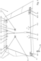
- Fig. 1 shows the two flaps in the closed state, viewed from the outside.
- the direction of travel FR of the underwater vehicle is shown in Fig. 1 from bottom to top.
- a left flap 1.1 and a right flap 1.2 are inserted into the outer shell 2.
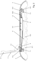
- Fig. 2 shows a cross-sectional view of the outer shell with the left flap 1.1 in the open state and the right flap in the closed state.
- the planes of the two flaps 1.1 and 1.2 are perpendicular to the plane of the drawing of Fig. 2 .
- the direction of travel FR is perpendicular to the plane of the drawing and points away from the viewer.
- a chamber K and several objects G.1, G.2, ... can be seen in this chamber K, whereby the flaps 1.1 and 1.2 can close this chamber K.
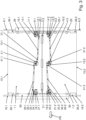
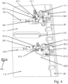
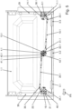
- Fig. 3 to Fig. 7 show the two flaps 1.1 and 1.2 in the closed state from the inside.
- the plane of the two flaps 1.1 and 1.2 lie in the drawing planes of Fig. 3 to Fig. 7
- the observer looks from inside the outer shell 2 at the two closed flaps 1.1 and 1.2.
- a reinforcement element 5.1 is mounted on the inside of the left flap 1.1, and a reinforcement element 5.2 is mounted on the inside of the right flap 1.2.
- the left flap 1.1 can rotate about a rotation axis 15.1 relative to the outer shell 2, and the right flap 1.2 can rotate about a rotation axis 15.2.
- the left rotation axis 15.1 is mounted on a left cross member 7.1, which is attached to the inside of the outer shell 2 and extends approximately parallel to the direction of travel FR, and the right rotation axis 15.2 is mounted on a right cross member 7.2.
- Three oval grip openings 3.1, 3.2 and 3.3 are formed between the two flaps 1.1 and 1.2, which are created by corresponding recesses in the free (inner) edges of the two flaps 1.1 and 1.2. A user can reach into such a grip opening from the outside in order to open a closed and unlocked flap 1.1 or 1.2.
- a receiving element 8 is mounted on the inside of the outer shell 2, which receives the reinforcement element 5.1 when the left flap 1.1 is closed and the reinforcement element 5.2 when the right flap 1.2 is closed.
- a front left locking claw 16.1 and a rear left locking claw 6.1 are mounted on the left flap 1.1 near the axis of rotation 15.1 - viewed in the direction of travel FR.
- the front left locking claw 16.1 is held on the flap 1.1 with a holder 26.1, the rear left locking claw 6.1 with a holder 36.1, cf. Fig. 3
- the heads of three screws of this bracket 26.1, 36.1 are in Fig. 1 to see the lower ends of these screws in Fig. 3 .
- a front right locking claw 16.2 and a rear right locking claw 6.2 are mounted on the right flap 1.2 near the axis of rotation 15.2, each with a holder 26.2, 36.2.
- a left central axis of rotation 4.1 is guided through the left flap 1.1.
- This left central axis of rotation 4.1 is arranged approximately in the middle between the front end - seen in the direction of travel FR - and the rear end of the left flap 1.1, namely near the free edge of the left flap 1.1 and near the gripping opening 3.2. Accordingly, a right central axis of rotation 4.2 is guided through the right flap 1.1.
- a user can place a tool on the left central axis of rotation 4.1 from the outside and use this tool to rotate the left central axis of rotation 4.1 in either direction.
- a rotation of the left central axis of rotation 4.1 causes the left flap 1.1 to be transferred from the locked to the unlocked state or vice versa from the unlocked to the unlocked state. locked state to the locked state. How this is achieved is described below.
- a hexagonal opening 0.1 can be seen on the outside of the left pivot axis 4.1.
- a user can place an Allen key on this opening 0.1 from the outside and press the key down to then rotate the left pivot axis 4.1 relative to the left flap 1.1. This is described in detail below.
- a user can rotate the right pivot axis 4.2 relative to the right flap 1.2 by placing the Allen key on the opening ⁇ .2 at the top of the right pivot axis 4.2.
- the circular surface at the end of the central pivot axes 4.1, 4.2 is flush with the flap 1.1, 1.2.
- the heads of the screws which attach the bracket 13.1, 13.2 to the flap 1.1, 1.2 are also flush with the flap 1.1, 1.2.
- Fig. 3 shows both flaps 1.1 and 1.2 in the closed state.
- the viewing direction is that of an observer who is located inside the outer shell 2 and looks vertically upwards at the closed flaps 1.1, 1.2.
- the left flap 1.1 (in Fig. 3 above) is locked, the right flap 1.2 (in Fig. 3 bottom) is not locked.
- the left flap 1.1 can be locked using a front left locking claw 19.1 and a rear left locking claw 9.1.
- the right flap 1.2 can be locked using a front right locking claw 19.2 and a rear right locking claw 9.2.
- a front segment of the rear left locking claw 9.1 is located below a counter element 30.1, cf. Fig.
- a front segment of the rear right locking claw 9.2 is located below a counter element 30.2 and a front segment of the front right locking claw 19.2 is located below a counter element 40.2.
- the two counter elements 30.1 and 30.2 are firmly mounted on a reinforcement 29.
- This reinforcement 29 is mounted on the inside of the outer shell 2, extends perpendicular to the direction of travel FR and is located between the closed flaps 1.1, 1.2 and the counter elements 30.1 and 30.2.
- the other two counter elements are firmly mounted on a reinforcement 39.
- the left locking claws 19.1 and 9.1 are in a locking position and the right locking claws 19.2 and 9.2 are in a release position.
- the left flap 1.1 is locked.
- Three edges of the left flap 1.1 are connected to the surrounding outer shell 2, namely one edge by the rotation axis 15.1 and two edges by a locking claw 19.1 and 9.1 each. If these two locking claws 19.1 and 9.1 are in the release position, the left flap 1.1 can be opened. The same applies to the right flap 1.2.
- the rear left locking claw 9.1 is firmly mounted on a rotation axis 11.1.
- this rotation axis 11.1 is rotatably mounted on the left flap 1.1.
- the rotation axis 11.1 and an approximately triangular plate 17.1 of the bracket 14.1 are attached to the inside of the left flap 1.1.
- Three screws are passed through the left flap 1.1 and hold the plate 17.1 of the bracket 14.1 inside the left flap 1.1.
- Fig. 1 the three heads of these three screws can be seen, which also end flush with the outer shell 2.
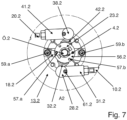
- Fig. 7 shows in a detailed view from the inside the right central axis of rotation 4.2 for the right flap 1.2, namely the area A2 of Fig. 6 .
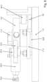
- Fig. 8 shows a detailed view from the inside and parallel to the plane of the right flap 1.2 the right rear locking claw 9.2.
- Fig. 9 shows in a detailed view from the outside and parallel to the plane of the right flap 1.2 the right central axis of rotation 4.2 for the right flap 1.2.
- a right central bracket 13.2 holds the right central pivot axis 4.2 rotatably on the right flap 1.2.
- Several screws 53.1, 53.2, ... are passed through the right flap, cf. Fig. 9 .
- a cross member 18.2 of the central right bracket 13.2 is mounted to the right flap 1.2 in a rotationally fixed manner using the screws 53.1, 53.2, ... In Fig. 1 and in Fig. 9 the heads of these screws 53.1, 53.2, ... can be seen.
- the rotation axis 4.2 is guided through a sleeve 58.2 of the bracket 13.2 and can be rotated about its own central axis relative to the sleeve 58.2.
- This sleeve 58.2 is embedded in the right flap 1.2 and is firmly connected to the inside of the cross member 18.2.
- a disk 60.2 is firmly mounted on the rotation axis 4.2. This disk 60.2 is accommodated in a corresponding recess in the cross member 18.2 and enables rotation of the rotation axis 4.2, but prevents the rotation axis 4.2 from being moved relative to the cross member 18.2 parallel to the central axis of the rotation axis 4.2.
- the two holding elements 62.a and 62.b are firmly connected to the axis of rotation 4.2.
- the stamp 55.2 can not only move linearly relative to the axis of rotation 4.2, but can also rotate around the common central axis.
- the stamp 55.2 can move relative to the two holding elements 62.a and 62.b along its own central axis.
- the stamp 55.2, the holding elements 62.a and 62.b and the lever arm 32.2 can be seen in detail.
- this lever arm 32.2 is connected to a connecting element 31.2 via a joint 28.2, cf. Fig. 7 and Fig. 9
- a screw 61.2 connects the lever arm 32.2 with the joint 28.2 and with the connecting element 32.
- the Connecting element 31.2 is connected to a rod 10.2.
- the distance between connecting element 31.2 and rod 10.2 can be changed using two screws.
- the length of rod 10.2 can be changed.
- a stop element 23.2 with a circular plate can be seen.
- This stop element 23.2 is firmly connected to the cross member 18.2 by means of two screws 59.a, 59.b and prevents the possible rotation of the axis of rotation 4.2 and thus of the lever arm 32.2 relative to the flap 1.2. In one embodiment, this stop element 23.2 also prevents a possible rotation of the piston 55.2.
- two locking pins 57.a and 57.b are mounted on a locking disk 56.2. This locking disk 56.2 is connected in a rotationally fixed manner to the axis of rotation 4.2 and, in one embodiment, also in a rotationally fixed manner to the punch 55.2.
- the stamp 55.2 engages from the inside in the hollow interior of the rotary axis 4.2 and can be moved relative to the rotary axis 4.2 along the common central axis.
- the two holding elements 62.a and 62.b can be moved together with the stamp 55.2 relative to the rotary axis 4.2.
- the stamp 55.2 can be moved linearly relative to the two holding elements 62.a and 62.b.
- the stop element 23.2 limits the movement of the stamp 55.2 away from the opening ⁇ .2.
- a compression spring 54.2 is supported on the rotary axis 4.2 (first embodiment) or on the two holding elements 62.a and 62.b (second embodiment) and strives to move the stamp 55.2 away from the stop element 23.2 into the Fig. 9
- the upper end of the piston 55.2 closes the hexagonal opening ⁇ .2 in the rotation axis 4.2 and prevents water from entering from the outside.
- the piston 55.2 When the piston 55.2 is moved linearly away from the opening ⁇ .2 relative to the axis of rotation 4.2, the opening ⁇ .2 is opened.
- the piston 55.2 is designed as a valve.
- the valve provided by the piston 55.2 compensates for a pressure difference between the inner area, for example of the chamber, which is closed by the flap 1.2, and the outer area outside the flap 1.2. Such a pressure difference can occur, for example, when the underwater vehicle surfaces from a dive and an excess pressure has developed in the chamber.
- the rod 10.2 is connected to another connecting element 25.2, see. Fig. 8 .
- This connecting element 25.2 is connected to a lever arm 12.2 via a joint 27.2.
- the lever arm 12.2 is firmly connected to the locking claw 9.2.
- the lever arm 12.2 and the locking claw 9.2 are mounted so that they can rotate on a pivot axis 11.2.
- An almost triangular plate 17.2 of a bracket 14.2 is mounted so that it cannot rotate on the right-hand flap 1.2 using three screws, whereby these three screws are passed through the right-hand flap 1.2, cf. Fig. 8 .
- the bracket 14.2 holds the rotary axis 11.2.
- the rotary axis 11.2 is guided through a sleeve which is firmly connected to the plate 17.2.
- the transmission means for the rear right locking claw 9.2 include the lever arms 32.2 and 12.2, the connecting elements 31.2 and 25.2 and the rigid rod 10.2.
- the three other locking claws 19.2, 9.1 and 19.1 have corresponding transmission means.
- FIG. 9 describes how the right flap 1.2 is opened.
- a user places an Allen key from the outside on the hexagonal opening ⁇ .2 in the rotary axis 4.2.
- the locking of the rotary axis 4.2 is released.
- the user presses on the Allen key and thereby moves the plunger 55.2 against the force of the spring 54.2 towards the stop element 23.2.
- the punch 55.2 is thereby displaced relative to the rotation axis 4.2 along the longitudinal axis of the rotation axis 4.2. Now the hexagon socket wrench and no longer the punch 55.2 closes the hexagonal opening ⁇ .2.
- the movement of the punch 55.2 causes the locking disk 56.2 with the two pins 57.a and 57.b to also be displaced away from the opening ⁇ .2 (in Fig. 9 downwards) and as a result the two pins 57.a and 57.b no longer engage in the two recesses in the stop element 23.2. This removes the locking of the rotation axis 4.2.
- the disk 60.2 also prevents the rotation axis 4.2 from being displaced relative to the cross member 18.2.
- the punch 55.2 is connected to the rotation axis 4.2 in a rotationally fixed manner and the holding elements 62.a, 62.b are firmly connected to the punch 55.2.
- the rotationally fixed punch 55.2 is rotated with the rotation axis 4.2.
- This also causes the holding elements 62.a and 62.b and thus the lever arms 32.2 and 42.2 (in Fig. 9 not shown).
- the rotation axis 4.2 is firmly connected to the two lever arms 32.2 and 42.2. A rotation of the rotation axis 42.2 is transmitted directly to the two lever arms 32.2 and 42.2.
- this rotation of the lever arms 32.2 and 42.2 is transmitted to the connecting elements 31.2 and 41.2 (in Fig. 9 not shown) and then onto bars 10.2 and 20.2 (in Fig. 9 not shown) and thus transferred to the associated locking claws 9.2 and 19.2.
- the rotation unlocks the flap 1.2.
- the user then removes the Allen key.
- the compression spring 54.2 moves the plunger 55.2 back into the locking position, which is shown in Fig. 9
- the user can turn the unlocked flap 1.2 using the recesses 3.1, 3.2, 3.3 and thereby open it. Later, the user can close the flap 1.2 again and lock it in the corresponding way.
- a third example shows an underwater vehicle according to one of the preceding examples, characterized in that the or each flap in the closed position together with the associated actuating element is flush with the outer hull 2.
- a sixth example shows an underwater vehicle according to example 5, characterized in that the connecting means is articulated both to the lever arm and to the further lever arm.
- a seventh example shows an underwater vehicle according to one of the preceding examples, characterized in that the length of the or at least one transmission means is variable.
- An eighth example shows an underwater vehicle according to one of the preceding examples, characterized in that the actuating element of the or at least one locking device is rotatably mounted and the transmission means of this locking device comprises a lever arm 32.1, 32.2, 42.1, 42.2 which is connected in a rotationally fixed manner to the actuating element.
- a ninth example shows an underwater vehicle according to one of the preceding examples, characterized in that an opening 0.1, ⁇ .2 is let into the or at least one flap and the locking device associated with this flap has a plunger 55.2, wherein the actuating element for this locking device can be actuated through the opening and wherein a spring element 54.2 strives to move the plunger into a closing position in which the plunger closes the opening in the flap.
- a twelfth example shows an underwater vehicle according to example 9 and example 11, characterized in that the spring element for the piston is additionally designed to hold the locking unit in the locking position.
Landscapes
- Engineering & Computer Science (AREA)
- Mechanical Engineering (AREA)
- Chemical & Material Sciences (AREA)
- Combustion & Propulsion (AREA)
- Ocean & Marine Engineering (AREA)
- Aviation & Aerospace Engineering (AREA)
- Lock And Its Accessories (AREA)
Claims (11)
- Véhicule sous-marin comprenant- une coque extérieure (2),- un volet (1.1, 1.2) relié à l'enveloppe extérieure et- un dispositif de blocage pour le volet (1.1, 1.2),le rabat (1.1, 1.2) étant mobile en va-et-vient entre une position fermée et une position ouverte,l'enveloppe extérieure entoure une zone intérieure et la sépare d'une zone extérieure, et le dispositif d'arrêt étant conçu pour verrouiller le volet (1.1, 1.2) se trouvant dans la position fermée,dans lequelle dispositif d'arrêt- au moins deux corps d'arrêt (9.1, 11.1, 14.1 et 19.1, 21.1, 24.1 et 9.2, 11.2, 14.2 et 19.2, 21.2, 24.2),- un élément d'actionnement monté mobile (4.1, 13.1 et 4.2, 13.2) et- pour chaque corps d'arrêt, un moyen de transmission (32.1, 31.1, 10.1, 25.1, 12.1 et 42.1, 41.1, 20.1, 35.1, 22.1 et 32.2, 31.2, 10.2, 25.2, 12.2, 55.2 et 42.2, 41.2, 20.2, 35.2, 22.2)comprend,les corps d'arrêt et les moyens de transmission se trouvant dans la zone intérieure lorsque le volet est fermé,l'élément d'actionnement pouvant être atteint depuis la zone extérieure lorsque le volet est fermé,les corps d'arrêt étant mobiles en va-et-vient par rapport au volet entre une position d'arrêt et une position de libération,les moyens de transmission étant reliés mécaniquement à l'élément d'actionnement et au corps d'arrêt associé, etle moyen de transmission du dispositif d'arrêt étant disposé de telle manière,qu'un actionnement de l'élément d'actionnement provoque un mouvement des corps d'arrêt entre la position d'arrêt et la position de libération ;
oùl'élément d'actionnement (4.1, 13.1 et 4.2, 13.2) comprend un axe de rotation d'actionnement (4.1, 4.2) logé de manière rotative,l'axe de rotation d'actionnement (4.1, 4.2) étant- peut tourner par rapport au volet associé et- est guidé à travers le volet ;
caractérisé en ce queune ouverture est ménagée dans le volet, un élément à ressort étant conçu pour déplacer un poinçon dans une position de fermeture, de sorte que l'ouverture est automatiquement fermée au moyen du poinçon, dans la mesure où l'élément d'actionnement n'est pas actionné ;dans lequel le poinçon peut être déplacé contre la force de ressort de l'élément de ressort pour libérer l'ouverture et déplacer l'élément d'actionnement à travers l'ouverture ;dans lequel le plongeur fournit une soupape pour équilibrer une différence de pression entre la zone intérieure et la zone extérieure lorsque le plongeur est déplacé à l'encontre de la force du ressort en s'éloignant de l'ouverture. - Véhicule sous-marin selon l'une quelconque des revendications précédentes, caractérisé en ce que
le volet en position fermée, y compris l'élément d'actionnement associé, affleure l'enveloppe extérieure (2). - Véhicule sous-marin selon l'une quelconque des revendications précédentes, caractérisé en ce queau moins un corps d'arrêt- un axe de rotation de corps d'arrêt (11.1, 11.2, 21.1, 21.2) ainsi que- un élément d'arrêt (9.1, 9.2, 19.1, 19.2) solidaire de l'axe de rotation du corps d'arrêt comprend un élément d'arrêt,l'axe de rotation du corps d'arrêt étant- est fixé de manière rotative sur le volet associé et- se trouve entièrement dans la zone intérieure etl'élément d'arrêt étant- est mobile entre la position de libération et la position de blocage, et- dans la position de blocage, il s'engage de l'intérieur sous l'enveloppe extérieure.
- Véhicule sous-marin selon l'une quelconque des revendications précédentes, caractérisé en ce quele moyen de transmission- un bras de levier (32.1, 32.2, 42.1, 42.2) qui est relié mécaniquement à l'élément de commande,- un autre bras de levier (12.1, 12.2, 22.1, 22.2), qui est relié mécaniquement au corps d'arrêt associé, ainsi que- un moyen de liaison (25.1, 10.1, 31.1 et 25.2, 10.2, 31.2 et 35.1, 20.1, 41.1 et 35.2, 20.2, 41.2) entre ces deux bras de leviercomprend.
- Véhicule sous-marin selon la revendication 4,
caractérisé en ce que
le moyen de liaison est articulé à la fois au bras de levier et à l'autre bras de levier. - Véhicule sous-marin selon l'une quelconque des revendications précédentes, caractérisé en ce que
la longueur du moyen de transmission est modifiable. - Véhicule sous-marin selon l'une quelconque des revendications précédentes, caractérisé en ce quel'élément d'actionnement du dispositif d'arrêt est monté à rotation, etle moyen de transmission de ce dispositif d'arrêt comprend un bras de levier (32.1, 32.2, 42.1, 42.2) solidaire en rotation de l'élément d'actionnement.
- Véhicule sous-marin selon la revendication 7,
caractérisé en ce quele moyen de transmission comprend le bras de levier (32.1, 32.2, 42.1, 42.2) qui est relié mécaniquement au poinçon, etl'élément de commande- est logé de manière rotative et- est solidaire en rotation du poinçon. - Véhicule sous-marin selon l'une quelconque des revendications précédentes, caractérisé en ce quele dispositif d'arrêt comprend en outre une unité d'arrêt (56.2, 57.a, 57.b, 54.2) pour l'élément d'actionnement,l'unité d'arrêt étant conçue à cet effet,- d'empêcher, dans une position de blocage, un mouvement de l'élément d'actionnement par rapport au clapet associé et- dans une position de libération, de permettre un tel mouvement.
- Véhicule sous-marin selon l'une quelconque des revendications 7 à 9,
caractérisé en ce que
l'élément de ressort pour le poinçon est en outre configuré pour maintenir l'unité d'arrêt dans la position d'arrêt. - Véhicule sous-marin selon l'une quelconque des revendications précédentes, caractérisé en ce quele véhicule sous-marin- au moins deux volets (1.1, 1.2), tous deux reliés de manière pivotante à la coque extérieure, et- respectivement un dispositif de blocage pour chaque volet comprend,de sorte que le véhicule sous-marin comporte au total au moins- quatre corps d'arrêt,- quatre moyens de transmission et- deux éléments d'actionnementcomprennent des moyens de transport.
Applications Claiming Priority (1)
| Application Number | Priority Date | Filing Date | Title |
|---|---|---|---|
| DE102018205487.8A DE102018205487A1 (de) | 2018-04-11 | 2018-04-11 | Unterwasserfahrzeug mit einer arretierbaren Klappe |
Publications (2)
| Publication Number | Publication Date |
|---|---|
| EP3552945A1 EP3552945A1 (fr) | 2019-10-16 |
| EP3552945B1 true EP3552945B1 (fr) | 2024-12-04 |
Family
ID=66102863
Family Applications (1)
| Application Number | Title | Priority Date | Filing Date |
|---|---|---|---|
| EP19166966.2A Active EP3552945B1 (fr) | 2018-04-11 | 2019-04-03 | Véhicule sous-marin doté d'un volet pouvant être bloqué |
Country Status (2)
| Country | Link |
|---|---|
| EP (1) | EP3552945B1 (fr) |
| DE (1) | DE102018205487A1 (fr) |
Families Citing this family (1)
| Publication number | Priority date | Publication date | Assignee | Title |
|---|---|---|---|---|
| CN110884613B (zh) * | 2019-11-28 | 2021-05-11 | 中国科学院沈阳自动化研究所 | 一种水下机器人的舱门系统 |
Citations (1)
| Publication number | Priority date | Publication date | Assignee | Title |
|---|---|---|---|---|
| DE202006004805U1 (de) * | 2006-03-25 | 2006-06-08 | Howaldtswerke-Deutsche Werft Gmbh | Unterseeboot |
Family Cites Families (3)
| Publication number | Priority date | Publication date | Assignee | Title |
|---|---|---|---|---|
| US3051280A (en) * | 1958-04-04 | 1962-08-28 | Boeing Co | Outward-opening plug type door for aircraft |
| DE102007041724B4 (de) * | 2007-09-04 | 2017-11-23 | Thyssenkrupp Marine Systems Gmbh | Unterseeboot mit einem außen angeordneten Behälter |
| CN201834177U (zh) * | 2010-08-26 | 2011-05-18 | 无锡市东舟船舶附件有限公司 | A60级快开闭防火水密舱口盖 |
-
2018
- 2018-04-11 DE DE102018205487.8A patent/DE102018205487A1/de not_active Withdrawn
-
2019
- 2019-04-03 EP EP19166966.2A patent/EP3552945B1/fr active Active
Patent Citations (1)
| Publication number | Priority date | Publication date | Assignee | Title |
|---|---|---|---|---|
| DE202006004805U1 (de) * | 2006-03-25 | 2006-06-08 | Howaldtswerke-Deutsche Werft Gmbh | Unterseeboot |
Also Published As
| Publication number | Publication date |
|---|---|
| EP3552945A1 (fr) | 2019-10-16 |
| DE102018205487A1 (de) | 2019-10-17 |
Similar Documents
| Publication | Publication Date | Title |
|---|---|---|
| DE60109697T2 (de) | Kraftfahrzeug mit voneinander unabhängigen Schwenk- und Schiebetüren | |
| EP3234289B1 (fr) | Organe d'actionnement pour porte d'armoire à équipement électrique | |
| DE3539480A1 (de) | Betaetigungsvorrichtung fuer ein frachtladetor | |
| DE202014102405U1 (de) | Verriegelungsvorrichtung für Schwenkschiebetüren von Fahrzeugen des öffentlichen Personenverkehrs; Schwenkschiebetür mit Verriegelungsvorrichtung | |
| DE102013222955A1 (de) | Doppelte Haubenverriegelungsanordnung | |
| DE102012010786A1 (de) | Panikschloss mit Selektionseinrichtung im Schlosskasten | |
| DE202015101373U1 (de) | Fahrzeug mit unterteilter Heckklappe | |
| EP2572415B1 (fr) | Agencement de porte pour une armoire d'appareils et procédé pour inverser le sens d'ouverture de porte | |
| DE202009007141U1 (de) | Wasserfahrzeug mit einem Plattformlift | |
| EP2094924A2 (fr) | Serrure pour portes d'aéronefs, en particulier d'hélicoptères | |
| EP0398106B1 (fr) | Dispositif pour la manoeuvre de pièces de carrosserie de véhicules automobiles pivotantes et/ou déplaçables | |
| DE10128866A1 (de) | Griffanordnung für ein deckelartiges Bauteil, insbesondere eine Heckklappe eines Kraftfahrzeugs | |
| EP3552945A1 (fr) | Véhicule sous-marin doté d'un volet pouvant être bloqué | |
| EP2016245A1 (fr) | Dispositf de fermeture | |
| DE102008064374B3 (de) | Öffnungs- und Schließvorrichtung eines Verdeckkastendeckels | |
| DE3915737A1 (de) | Einrichtung zum betaetigen von schwenkbaren und/oder verschiebbaren karosserieteilen an kraftfahrzeugen | |
| DE3608369C2 (fr) | ||
| EP2927514B1 (fr) | Revêtement d'une ouverture de réception d'un compartiment de réception | |
| EP3287579B1 (fr) | Dispositif de fermeture pour porte | |
| DE102005061127A1 (de) | Luftfahrzeugtür-Anordnung sowie Luftfahrzeugrumpf mit einer derartigen Luftfahrzeugtür-Anordnung | |
| DE20017674U1 (de) | Lösbare mechanische Verriegelungsanordnung zwischen einem schwenkbaren Deckel und einem Behälter, vorzugsweise einem Gepäckfach | |
| EP2499315B1 (fr) | Serrure de porte de véhicule automobile | |
| DE102005030705B4 (de) | Kraftstofftankluke für Kraftfahrzeuge | |
| EP3269902B1 (fr) | Ensemble d'actionnement pour une fermeture de bâtiment, fermeture de bâtiment correspondante, kit de montage destiné à produire des fermetures de bâtiments et procédé d'équipement d'une fermeture de bâtiment | |
| DE2918837A1 (de) | Notentriegelungseinrichtung an einem mit einer zentralen verriegelungsanlage ausgeruesteten schloss fuer tueren oder raumklappen von kraftfahrzeugen, insbesondere omnibussen |
Legal Events
| Date | Code | Title | Description |
|---|---|---|---|
| PUAI | Public reference made under article 153(3) epc to a published international application that has entered the european phase |
Free format text: ORIGINAL CODE: 0009012 |
|
| STAA | Information on the status of an ep patent application or granted ep patent |
Free format text: STATUS: THE APPLICATION HAS BEEN PUBLISHED |
|
| AK | Designated contracting states |
Kind code of ref document: A1 Designated state(s): AL AT BE BG CH CY CZ DE DK EE ES FI FR GB GR HR HU IE IS IT LI LT LU LV MC MK MT NL NO PL PT RO RS SE SI SK SM TR |
|
| AX | Request for extension of the european patent |
Extension state: BA ME |
|
| STAA | Information on the status of an ep patent application or granted ep patent |
Free format text: STATUS: REQUEST FOR EXAMINATION WAS MADE |
|
| 17P | Request for examination filed |
Effective date: 20200416 |
|
| RBV | Designated contracting states (corrected) |
Designated state(s): AL AT BE BG CH CY CZ DE DK EE ES FI FR GB GR HR HU IE IS IT LI LT LU LV MC MK MT NL NO PL PT RO RS SE SI SK SM TR |
|
| RAP1 | Party data changed (applicant data changed or rights of an application transferred) |
Owner name: THYSSENKRUPP MARINE SYSTEMS GMBH Owner name: THYSSENKRUPP AG |
|
| STAA | Information on the status of an ep patent application or granted ep patent |
Free format text: STATUS: EXAMINATION IS IN PROGRESS |
|
| 17Q | First examination report despatched |
Effective date: 20211011 |
|
| 17Q | First examination report despatched |
Effective date: 20211022 |
|
| GRAP | Despatch of communication of intention to grant a patent |
Free format text: ORIGINAL CODE: EPIDOSNIGR1 |
|
| STAA | Information on the status of an ep patent application or granted ep patent |
Free format text: STATUS: GRANT OF PATENT IS INTENDED |
|
| INTG | Intention to grant announced |
Effective date: 20240705 |
|
| GRAS | Grant fee paid |
Free format text: ORIGINAL CODE: EPIDOSNIGR3 |
|
| GRAA | (expected) grant |
Free format text: ORIGINAL CODE: 0009210 |
|
| STAA | Information on the status of an ep patent application or granted ep patent |
Free format text: STATUS: THE PATENT HAS BEEN GRANTED |
|
| AK | Designated contracting states |
Kind code of ref document: B1 Designated state(s): AL AT BE BG CH CY CZ DE DK EE ES FI FR GB GR HR HU IE IS IT LI LT LU LV MC MK MT NL NO PL PT RO RS SE SI SK SM TR |
|
| REG | Reference to a national code |
Ref country code: GB Ref legal event code: FG4D Free format text: NOT ENGLISH |
|
| REG | Reference to a national code |
Ref country code: CH Ref legal event code: EP |
|
| REG | Reference to a national code |
Ref country code: DE Ref legal event code: R096 Ref document number: 502019012576 Country of ref document: DE |
|
| REG | Reference to a national code |
Ref country code: IE Ref legal event code: FG4D Free format text: LANGUAGE OF EP DOCUMENT: GERMAN |
|
| REG | Reference to a national code |
Ref country code: DE Ref legal event code: R084 Ref document number: 502019012576 Country of ref document: DE |
|
| REG | Reference to a national code |
Ref country code: LT Ref legal event code: MG9D |
|
| REG | Reference to a national code |
Ref country code: NL Ref legal event code: MP Effective date: 20241204 |
|
| PG25 | Lapsed in a contracting state [announced via postgrant information from national office to epo] |
Ref country code: HR Free format text: LAPSE BECAUSE OF FAILURE TO SUBMIT A TRANSLATION OF THE DESCRIPTION OR TO PAY THE FEE WITHIN THE PRESCRIBED TIME-LIMIT Effective date: 20241204 |
|
| PG25 | Lapsed in a contracting state [announced via postgrant information from national office to epo] |
Ref country code: FI Free format text: LAPSE BECAUSE OF FAILURE TO SUBMIT A TRANSLATION OF THE DESCRIPTION OR TO PAY THE FEE WITHIN THE PRESCRIBED TIME-LIMIT Effective date: 20241204 |
|
| PG25 | Lapsed in a contracting state [announced via postgrant information from national office to epo] |
Ref country code: BG Free format text: LAPSE BECAUSE OF FAILURE TO SUBMIT A TRANSLATION OF THE DESCRIPTION OR TO PAY THE FEE WITHIN THE PRESCRIBED TIME-LIMIT Effective date: 20241204 |
|
| PG25 | Lapsed in a contracting state [announced via postgrant information from national office to epo] |
Ref country code: ES Free format text: LAPSE BECAUSE OF FAILURE TO SUBMIT A TRANSLATION OF THE DESCRIPTION OR TO PAY THE FEE WITHIN THE PRESCRIBED TIME-LIMIT Effective date: 20241204 |
|
| PG25 | Lapsed in a contracting state [announced via postgrant information from national office to epo] |
Ref country code: NO Free format text: LAPSE BECAUSE OF FAILURE TO SUBMIT A TRANSLATION OF THE DESCRIPTION OR TO PAY THE FEE WITHIN THE PRESCRIBED TIME-LIMIT Effective date: 20250304 |
|
| PG25 | Lapsed in a contracting state [announced via postgrant information from national office to epo] |
Ref country code: LV Free format text: LAPSE BECAUSE OF FAILURE TO SUBMIT A TRANSLATION OF THE DESCRIPTION OR TO PAY THE FEE WITHIN THE PRESCRIBED TIME-LIMIT Effective date: 20241204 Ref country code: GR Free format text: LAPSE BECAUSE OF FAILURE TO SUBMIT A TRANSLATION OF THE DESCRIPTION OR TO PAY THE FEE WITHIN THE PRESCRIBED TIME-LIMIT Effective date: 20250305 |
|
| PG25 | Lapsed in a contracting state [announced via postgrant information from national office to epo] |
Ref country code: RS Free format text: LAPSE BECAUSE OF FAILURE TO SUBMIT A TRANSLATION OF THE DESCRIPTION OR TO PAY THE FEE WITHIN THE PRESCRIBED TIME-LIMIT Effective date: 20250304 |
|
| PG25 | Lapsed in a contracting state [announced via postgrant information from national office to epo] |
Ref country code: NL Free format text: LAPSE BECAUSE OF FAILURE TO SUBMIT A TRANSLATION OF THE DESCRIPTION OR TO PAY THE FEE WITHIN THE PRESCRIBED TIME-LIMIT Effective date: 20241204 |
|
| PG25 | Lapsed in a contracting state [announced via postgrant information from national office to epo] |
Ref country code: SM Free format text: LAPSE BECAUSE OF FAILURE TO SUBMIT A TRANSLATION OF THE DESCRIPTION OR TO PAY THE FEE WITHIN THE PRESCRIBED TIME-LIMIT Effective date: 20241204 |
|
| PG25 | Lapsed in a contracting state [announced via postgrant information from national office to epo] |
Ref country code: PL Free format text: LAPSE BECAUSE OF FAILURE TO SUBMIT A TRANSLATION OF THE DESCRIPTION OR TO PAY THE FEE WITHIN THE PRESCRIBED TIME-LIMIT Effective date: 20241204 |
|
| PGFP | Annual fee paid to national office [announced via postgrant information from national office to epo] |
Ref country code: DE Payment date: 20250422 Year of fee payment: 7 |
|
| PG25 | Lapsed in a contracting state [announced via postgrant information from national office to epo] |
Ref country code: IS Free format text: LAPSE BECAUSE OF FAILURE TO SUBMIT A TRANSLATION OF THE DESCRIPTION OR TO PAY THE FEE WITHIN THE PRESCRIBED TIME-LIMIT Effective date: 20250404 |
|
| PG25 | Lapsed in a contracting state [announced via postgrant information from national office to epo] |
Ref country code: PT Free format text: LAPSE BECAUSE OF FAILURE TO SUBMIT A TRANSLATION OF THE DESCRIPTION OR TO PAY THE FEE WITHIN THE PRESCRIBED TIME-LIMIT Effective date: 20250404 |
|
| PG25 | Lapsed in a contracting state [announced via postgrant information from national office to epo] |
Ref country code: EE Free format text: LAPSE BECAUSE OF FAILURE TO SUBMIT A TRANSLATION OF THE DESCRIPTION OR TO PAY THE FEE WITHIN THE PRESCRIBED TIME-LIMIT Effective date: 20241204 |
|
| PGFP | Annual fee paid to national office [announced via postgrant information from national office to epo] |
Ref country code: FR Payment date: 20250425 Year of fee payment: 7 |
|
| PG25 | Lapsed in a contracting state [announced via postgrant information from national office to epo] |
Ref country code: RO Free format text: LAPSE BECAUSE OF FAILURE TO SUBMIT A TRANSLATION OF THE DESCRIPTION OR TO PAY THE FEE WITHIN THE PRESCRIBED TIME-LIMIT Effective date: 20241204 |
|
| PG25 | Lapsed in a contracting state [announced via postgrant information from national office to epo] |
Ref country code: SK Free format text: LAPSE BECAUSE OF FAILURE TO SUBMIT A TRANSLATION OF THE DESCRIPTION OR TO PAY THE FEE WITHIN THE PRESCRIBED TIME-LIMIT Effective date: 20241204 |
|
| PG25 | Lapsed in a contracting state [announced via postgrant information from national office to epo] |
Ref country code: CZ Free format text: LAPSE BECAUSE OF FAILURE TO SUBMIT A TRANSLATION OF THE DESCRIPTION OR TO PAY THE FEE WITHIN THE PRESCRIBED TIME-LIMIT Effective date: 20241204 |
|
| PG25 | Lapsed in a contracting state [announced via postgrant information from national office to epo] |
Ref country code: IT Free format text: LAPSE BECAUSE OF FAILURE TO SUBMIT A TRANSLATION OF THE DESCRIPTION OR TO PAY THE FEE WITHIN THE PRESCRIBED TIME-LIMIT Effective date: 20241204 |
|
| REG | Reference to a national code |
Ref country code: DE Ref legal event code: R081 Ref document number: 502019012576 Country of ref document: DE Owner name: THYSSENKRUPP AG, DE Free format text: FORMER OWNERS: THYSSENKRUPP AG, 45143 ESSEN, DE; THYSSENKRUPP MARINE SYSTEMS GMBH, 24143 KIEL, DE Ref country code: DE Ref legal event code: R081 Ref document number: 502019012576 Country of ref document: DE Owner name: TKMS GMBH, DE Free format text: FORMER OWNERS: THYSSENKRUPP AG, 45143 ESSEN, DE; THYSSENKRUPP MARINE SYSTEMS GMBH, 24143 KIEL, DE |
|
| REG | Reference to a national code |
Ref country code: DE Ref legal event code: R097 Ref document number: 502019012576 Country of ref document: DE |
|
| PG25 | Lapsed in a contracting state [announced via postgrant information from national office to epo] |
Ref country code: SE Free format text: LAPSE BECAUSE OF FAILURE TO SUBMIT A TRANSLATION OF THE DESCRIPTION OR TO PAY THE FEE WITHIN THE PRESCRIBED TIME-LIMIT Effective date: 20241204 |
|
| PG25 | Lapsed in a contracting state [announced via postgrant information from national office to epo] |
Ref country code: DK Free format text: LAPSE BECAUSE OF FAILURE TO SUBMIT A TRANSLATION OF THE DESCRIPTION OR TO PAY THE FEE WITHIN THE PRESCRIBED TIME-LIMIT Effective date: 20241204 |
|
| PLBE | No opposition filed within time limit |
Free format text: ORIGINAL CODE: 0009261 |
|
| STAA | Information on the status of an ep patent application or granted ep patent |
Free format text: STATUS: NO OPPOSITION FILED WITHIN TIME LIMIT |
|
| REG | Reference to a national code |
Ref country code: CH Ref legal event code: L10 Free format text: ST27 STATUS EVENT CODE: U-0-0-L10-L00 (AS PROVIDED BY THE NATIONAL OFFICE) Effective date: 20251015 |
|
| 26N | No opposition filed |
Effective date: 20250905 |
|
| REG | Reference to a national code |
Ref country code: CH Ref legal event code: H13 Free format text: ST27 STATUS EVENT CODE: U-0-0-H10-H13 (AS PROVIDED BY THE NATIONAL OFFICE) Effective date: 20251125 |
|
| PG25 | Lapsed in a contracting state [announced via postgrant information from national office to epo] |
Ref country code: LU Free format text: LAPSE BECAUSE OF NON-PAYMENT OF DUE FEES Effective date: 20250403 |
|
| PG25 | Lapsed in a contracting state [announced via postgrant information from national office to epo] |
Ref country code: MC Free format text: LAPSE BECAUSE OF FAILURE TO SUBMIT A TRANSLATION OF THE DESCRIPTION OR TO PAY THE FEE WITHIN THE PRESCRIBED TIME-LIMIT Effective date: 20241204 |
|
| GBPC | Gb: european patent ceased through non-payment of renewal fee |
Effective date: 20250403 |
|
| REG | Reference to a national code |
Ref country code: BE Ref legal event code: MM Effective date: 20250430 |
|
| PG25 | Lapsed in a contracting state [announced via postgrant information from national office to epo] |
Ref country code: GB Free format text: LAPSE BECAUSE OF NON-PAYMENT OF DUE FEES Effective date: 20250403 |
|
| PG25 | Lapsed in a contracting state [announced via postgrant information from national office to epo] |
Ref country code: BE Free format text: LAPSE BECAUSE OF NON-PAYMENT OF DUE FEES Effective date: 20250430 |
|
| PG25 | Lapsed in a contracting state [announced via postgrant information from national office to epo] |
Ref country code: CH Free format text: LAPSE BECAUSE OF NON-PAYMENT OF DUE FEES Effective date: 20250430 |
|
| PG25 | Lapsed in a contracting state [announced via postgrant information from national office to epo] |
Ref country code: IE Free format text: LAPSE BECAUSE OF NON-PAYMENT OF DUE FEES Effective date: 20250403 |