EP3552945B1 - Underwater vehicle comprising a lockable flap - Google Patents
Underwater vehicle comprising a lockable flap Download PDFInfo
- Publication number
- EP3552945B1 EP3552945B1 EP19166966.2A EP19166966A EP3552945B1 EP 3552945 B1 EP3552945 B1 EP 3552945B1 EP 19166966 A EP19166966 A EP 19166966A EP 3552945 B1 EP3552945 B1 EP 3552945B1
- Authority
- EP
- European Patent Office
- Prior art keywords
- locking
- flap
- underwater vehicle
- actuating element
- rotation
- Prior art date
- Legal status (The legal status is an assumption and is not a legal conclusion. Google has not performed a legal analysis and makes no representation as to the accuracy of the status listed.)
- Active
Links
Images


Classifications
-
- B—PERFORMING OPERATIONS; TRANSPORTING
- B63—SHIPS OR OTHER WATERBORNE VESSELS; RELATED EQUIPMENT
- B63B—SHIPS OR OTHER WATERBORNE VESSELS; EQUIPMENT FOR SHIPPING
- B63B3/00—Hulls characterised by their structure or component parts
- B63B3/13—Hulls built to withstand hydrostatic pressure when fully submerged, e.g. submarine hulls
-
- B—PERFORMING OPERATIONS; TRANSPORTING
- B63—SHIPS OR OTHER WATERBORNE VESSELS; RELATED EQUIPMENT
- B63B—SHIPS OR OTHER WATERBORNE VESSELS; EQUIPMENT FOR SHIPPING
- B63B19/00—Arrangements or adaptations of ports, doors, windows, port-holes, or other openings or covers
- B63B19/08—Ports or like openings in vessels' sides or at the vessels' bow or stern
-
- B—PERFORMING OPERATIONS; TRANSPORTING
- B63—SHIPS OR OTHER WATERBORNE VESSELS; RELATED EQUIPMENT
- B63G—OFFENSIVE OR DEFENSIVE ARRANGEMENTS ON VESSELS; MINE-LAYING; MINE-SWEEPING; SUBMARINES; AIRCRAFT CARRIERS
- B63G8/00—Underwater vessels, e.g. submarines; Equipment specially adapted therefor
-
- B—PERFORMING OPERATIONS; TRANSPORTING
- B63—SHIPS OR OTHER WATERBORNE VESSELS; RELATED EQUIPMENT
- B63B—SHIPS OR OTHER WATERBORNE VESSELS; EQUIPMENT FOR SHIPPING
- B63B19/00—Arrangements or adaptations of ports, doors, windows, port-holes, or other openings or covers
- B63B19/12—Hatches; Hatchways
- B63B19/14—Hatch covers
-
- B—PERFORMING OPERATIONS; TRANSPORTING
- B63—SHIPS OR OTHER WATERBORNE VESSELS; RELATED EQUIPMENT
- B63G—OFFENSIVE OR DEFENSIVE ARRANGEMENTS ON VESSELS; MINE-LAYING; MINE-SWEEPING; SUBMARINES; AIRCRAFT CARRIERS
- B63G8/00—Underwater vessels, e.g. submarines; Equipment specially adapted therefor
- B63G8/40—Rescue equipment for personnel
- B63G8/41—Capsules, chambers, water-tight boats or the like, detachable from the submarine
Definitions
- the invention relates to an underwater vehicle with a flap and with a locking device for locking this flap.
- DE 20 2006 004 805 U1 discloses a submarine in which boat components arranged in a space between the pressure hull and the outer skin are reliably protected by a cover, but at the same time easy and quick access is possible.
- CN 201 834 177 U reveals a quick opening and closing fireproof and watertight hatch cover.
- the object of the invention is to provide an underwater vehicle with the features of the preamble of claim 1, in which the locking device locks the associated flap more securely and can be operated more easily than in known underwater vehicles.
- Each transmission means is mechanically connected to the actuating element and to the associated locking body.
- the outer shell encloses an interior area.
- the outer shell separates this interior area from an exterior area outside the outer shell.
- the or each flap is mechanically connected to the outer shell and can be moved back and forth between a closed position and an open position relative to the outer shell.
- each locking element and each transmission device are located inside.
- the actuating element for this flap can be reached from outside when the flap is closed.
- Each locking body can be moved back and forth between a locking position and a release position.
- the actuating element can be moved relative to the associated flap and thus actuated from the outside.
- Each transmission means connected to the actuating element transfers a movement of the actuating element to the associated locking body and thereby causes the locking body to be moved from one position to the other.
- the flap is locked or unlocked by this movement of several locking bodies.
- the underwater vehicle comprises an outer shell and at least one flap.
- the or each flap is movably embedded in the outer shell and can be opened and closed again.
- access to the interior is possible from the outside.
- the flap When the flap is open, it is possible to move objects into an interior chamber or to remove objects from this chamber.
- the flap protects the interior, for example the chamber, from environmental influences.
- the flap it is possible for the flap to be designed in such a way that the interior is protected from the ingress of water. Objects in the chamber cannot be washed away.
- a watertight container to be located in the chamber at least temporarily, which in turn holds objects. The closed and locked flap prevents this container from floating away or becoming damaged or opening on its own or being removed without authorization.
- the locking device is able to lock the associated closed flap and thus prevent the closed and locked flap from opening unintentionally. Without the locking device, this could happen in particular if the underwater vehicle rolls back and forth in the water or otherwise moves back and forth relative to the surrounding water or is subjected to a sudden load.
- the locked flap can be unlocked from the outside.
- the or each locking device comprises at least two locking bodies. These locking bodies are spatially spaced from one another. As a result, the flap is locked at at least two points, with a gap occurring between these points. Compared to a single locking body per flap, the use of at least two locking bodies further prevents the risk of the closed and locked flap opening unintentionally. Even if one locking body is not in a locking position due to a fault, the or at least one other locking body still locks the flap. If the closed flap is bent in the opening direction, the resulting gap between the flap and the outer shell is smaller with at least two locking bodies than with just a single locking body.
- each locking body for the flap or a flap is connected to the same actuating element via a transmission means.
- this one actuating element By actuating this one actuating element, all locking bodies for this flap can be moved to the locking position with one handle or to the release position with one handle. It is not necessary for a user to actuate several actuating elements one after the other to lock or unlock the same flap.
- This design saves time.
- This design is particularly advantageous if the flap or a flap is to be locked or unlocked when the underwater vehicle is submerged. This process usually requires a diver to descend to the underwater vehicle and work underwater. Visibility underwater is often much worse than above water or on land, and a diver can only stay underwater for a limited period of time. For both reasons, it is advantageous to only have to actuate a single actuating element. The diver only needs to find and actuate a single actuating element to open the flap or a flap.
- the actuating element of the or each locking device can be reached from the outside.
- the underwater vehicle does not necessarily have to have an interior area in which a person can stay.
- each locking body and each transmission means are arranged entirely in the interior.
- the outer shell and the closed flap therefore protect the locking bodies and the transmission means from environmental influences, in particular from the surrounding water.
- no locking body or transmission means impairs the hydrodynamic properties of the underwater vehicle when traveling above or below water, which could be the case if a locking body or transmission means were arranged at least partially outside the interior.
- no locking body and no transmission means can cause turbulence in the water.
- the actuation of an actuating element causes the at least two locking bodies of this locking device to be moved simultaneously from one position to the other position.
- the actuating element comprises an actuating axis of rotation.
- This actuating axis of rotation is guided through the associated flap.
- a user can rotate this actuating axis of rotation from the outside and thereby actuate the transmission means and move the at least two locking bodies that are connected to this actuating element.
- the actuating axis of rotation of the actuating element is mechanically connected to the two transmission means in the interior.
- Each transmission means connected to this actuating element can be guided completely in the interior and along the flap. It is not necessary to guide the transmission means along an edge of the flap.
- At least one recess is provided in the or each flap.
- at least one handle is attached to the flap.
- this recess or this handle a user, such as a diver, can move the unlocked flap relative to the outer shell and thereby open it. The user does not need to carry a tool to move the unlocked flap.
- the or each flap is flush with the outer hull when it is in the closed state.
- the flap does not impair the hydrodynamic properties of the underwater vehicle or a signature of the underwater vehicle, i.e. its recognizability in a radar image or a sonar image.
- the end piece of the actuating element that is still pointing outwards is also flush with the outer hull, i.e. does not protrude.
- This design further improves the hydrodynamic properties of the underwater vehicle in the water.
- a recess for an Allen key is recessed into the actuating axis of rotation, whereby this recess is accessible from the outside. A user can rotate the actuating axis of rotation with a commercially available Allen key and thereby actuate the actuating element and lock or unlock the flap. No special tool is required for actuation.
- the or at least one locking body comprises a locking element and a locking body rotation axis.
- the locking element is fixedly mounted on the locking body rotation axis.
- the locking body rotation axis is rotatable and mounted from the inside on the associated flap. In the locking position, the locking element at least partially reaches under the outer shell, so that the outer shell is located between the locking element and the outer area. In the release position, the locking element does not overlap with the outer shell.
- the transmission means is able to move the locking body rotation axis and thus the locking element. It is not necessary for the transmission means to be directly connected to the locking element.
- the or at least one transmission means comprises two lever arms and a connecting means between these two lever arms.
- the first lever arm is connected to the actuating element, in the case of a rotatable actuating element, in a rotationally fixed manner to the actuating axis of rotation, the other lever arm to the locking body axis of rotation.
- Actuation of the actuating element causes the actuating axis of rotation to be rotated, the first lever arm on the rotated actuating axis of rotation moves the connecting means and the moved connecting means rotates the locking body axis of rotation.
- the lever arm connected to the If the first lever arm connected to the actuating element is moved in another way, the connecting means moves.
- a movement of the connecting means causes the second lever arm to be moved and the locking element to be rotated from one position to the other position.
- the connecting means extends along a longitudinal axis and has, for example, the shape of a rod.
- the length of this connecting means can preferably be changed, for example so that each locking body can be moved easily enough and, on the other hand, the flap is securely locked and released safely.
- the possibility of changing the length makes it easier to adapt the locking device to different environmental conditions, for example to different water temperatures or desired diving depths.
- an opening is let into the flap or a flap.
- a user can reach the actuating element through this opening using a suitable tool.
- this opening is automatically closed as long as the user does not actuate the actuating element.
- a spring element tends to move a plunger into a closed position. In this closed position, the plunger closes the opening. The plunger thus prevents water from penetrating through the opening into the interior area enclosed by the outer shell.
- the spring force exerted by the spring element is large enough for the plunger to maintain its closed position up to a certain diving depth of the underwater vehicle. Thanks to the spring element, the plunger automatically closes the opening without user intervention being required to close it.
- the spring is supported on the actuating element.
- the plunger can be moved against the spring force of this spring element to release the opening and to enable the actuating element to be moved through the opening.
- the plunger can be moved from the outside against the spring force by inserting a suitable tool through the opening and pressing it against the plunger. This design enables a user, for example a diver, to insert a tool into the opening and first move the plunger against the spring force from the closed position and then actuate the actuating element without first having to pull the tool out of the opening again.
- this piston also provides a valve. At least when the piston is moved away from the opening against the spring force, this valve compensates for a pressure difference between the inner and outer areas. This design in particular prevents the pressure difference from causing the unlocked flap to open abruptly when the pressure in the inner area is significantly higher.
- the or at least one actuating element is mounted so that it can rotate.
- a rotation of the actuating element causes each locking body of the associated locking device to be moved from one position to the other position. It is also possible for the or at least one actuating element to be mounted so that it can move and a displacement of the actuating element causes the associated locking body to be moved from one position to the other position.
- each transmission means has a lever arm. The at least two lever arms are connected in a rotationally fixed manner to the rotatable actuating element.
- the design with the stamp can be combined with the design with the rotatably mounted actuating element.
- a user moves the stamp away from the opening by inserting a tool into the opening and then actuates the actuating element by rotating the inserted tool.
- the rotatably mounted actuating element is connected to the stamp in a rotationally fixed manner.
- the stamp is mechanically connected to each transmission means of this locking device.
- a rotation of the actuating element therefore causes the stamp to rotate.
- Each transmission means transmits the rotation of the stamp to the associated locking body.
- This embodiment enables a particularly compact design, in particular because the axis of rotation of the actuating element can coincide with the axis of rotation of the stamp and because the stamp has two functions, namely, on the one hand, to seal the opening and, on the other hand, to transmit the rotation of the actuating element to the transmission means. Two different components are therefore not required.
- the actuating element can rotate relative to the stamp.
- the or at least one locking device additionally has a locking unit which is movable between a locking position and a release position.
- this locking unit prevents the actuating element of this locking device from moving unintentionally and thus the associated flap is no longer locked.
- this locking unit prevents the actuating element from moving without user intervention in such a way that the locking bodies of this locking device are moved into the release position or that the movement of a locking body or a transmission means causes a movement of the actuating element and thus a movement of each locking body into the release position.
- the design with the locking unit can be combined with the design that provides a stamp and a spring element.
- the same spring element has two functions at the same time: Firstly, the spring element holds the stamp in the closed position. Secondly, the spring element holds the locking unit for the actuating element in the locked position.
- This design enables a particularly compact construction and saves space compared to a design in which two different elements hold the stamp in the closed position and the locking unit in the locked position. When the stamp is moved against the spring force, the locking unit is simultaneously moved into the release position.
- At least two flaps are rotatably embedded in the outer hull.
- each flap can be opened and closed independently of the or any other flap. Locked and unlocked in the closed position. This makes it easier to gain access to the interior from different directions.
- only one flap can be opened and the or any other flap remains closed and locked, or both or at least two flaps are opened and unlocked. This makes it possible to create either a smaller opening or a larger opening to the interior.
- Each flap is assigned a locking device, each with at least two locking bodies, two transmission means and an actuating element.
- the underwater vehicle therefore comprises a total of at least two actuating elements, at least four locking bodies and at least four transmission means.
- the watercraft with the flap and the locking device can be a surface vehicle or an underwater vehicle and can have its own propulsion or be towed through the water by another vehicle.
- the watercraft can be a manned or unmanned watercraft.
- the outer hull can also be a pressure hull of the underwater vehicle or enclose the pressure hull, with the pressure hull being located in the interior.
- the outer shell can also enclose only part of the pressure hull. It is also possible that the underwater vehicle is unmanned and does not have a pressure hull that encloses an interior area for crew members. If the underwater vehicle is in a floating position above water, the flap can be located below or above the waterline.
- the invention is used to lock two flaps, these two flaps being rotatably inserted into the outer hull of an underwater vehicle with a pressure hull.
- the two flaps When the two flaps are opened, they provide access to a chamber in the inner region of the outer hull.
- the pressure hull of the underwater vehicle is arranged in the inner region of the outer hull, and this chamber is located between the outer hull and the inner region. It is also possible for the outer hull to only surround an upper part of the pressure hull, for example placed on top of the pressure hull.
- the two flaps are closed, they are flush with the rest of the underwater vehicle's outer hull.
- each flap can be opened and closed independently of the other flap.
- each closed flap can be switched to a locked (arrested) or unlocked (unlocked) state independently of the other flap.
- the flap can only be opened when it is not locked. By switching the closed flap to the locked state, it is prevented from opening accidentally on its own.
- the two flaps are made of glass fiber reinforced plastic so that they are light and can be rotated relatively easily.
- a user can move each door from the locked to the unlocked state and then open the unlocked door to insert or remove at least one object into the chamber. It is desirable that the door can be unlocked and opened even when the underwater vehicle is fully submerged, for example by a diver.
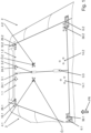
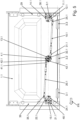
- Fig. 1 shows the two flaps in the closed state, viewed from the outside.
- the direction of travel FR of the underwater vehicle is shown in Fig. 1 from bottom to top.
- a left flap 1.1 and a right flap 1.2 are inserted into the outer shell 2.
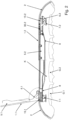
- Fig. 2 shows a cross-sectional view of the outer shell with the left flap 1.1 in the open state and the right flap in the closed state.
- the planes of the two flaps 1.1 and 1.2 are perpendicular to the plane of the drawing of Fig. 2 .
- the direction of travel FR is perpendicular to the plane of the drawing and points away from the viewer.
- a chamber K and several objects G.1, G.2, ... can be seen in this chamber K, whereby the flaps 1.1 and 1.2 can close this chamber K.
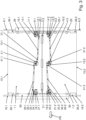
- Fig. 3 to Fig. 7 show the two flaps 1.1 and 1.2 in the closed state from the inside.
- the plane of the two flaps 1.1 and 1.2 lie in the drawing planes of Fig. 3 to Fig. 7
- the observer looks from inside the outer shell 2 at the two closed flaps 1.1 and 1.2.
- a reinforcement element 5.1 is mounted on the inside of the left flap 1.1, and a reinforcement element 5.2 is mounted on the inside of the right flap 1.2.
- the left flap 1.1 can rotate about a rotation axis 15.1 relative to the outer shell 2, and the right flap 1.2 can rotate about a rotation axis 15.2.
- the left rotation axis 15.1 is mounted on a left cross member 7.1, which is attached to the inside of the outer shell 2 and extends approximately parallel to the direction of travel FR, and the right rotation axis 15.2 is mounted on a right cross member 7.2.
- Three oval grip openings 3.1, 3.2 and 3.3 are formed between the two flaps 1.1 and 1.2, which are created by corresponding recesses in the free (inner) edges of the two flaps 1.1 and 1.2. A user can reach into such a grip opening from the outside in order to open a closed and unlocked flap 1.1 or 1.2.
- a receiving element 8 is mounted on the inside of the outer shell 2, which receives the reinforcement element 5.1 when the left flap 1.1 is closed and the reinforcement element 5.2 when the right flap 1.2 is closed.
- a front left locking claw 16.1 and a rear left locking claw 6.1 are mounted on the left flap 1.1 near the axis of rotation 15.1 - viewed in the direction of travel FR.
- the front left locking claw 16.1 is held on the flap 1.1 with a holder 26.1, the rear left locking claw 6.1 with a holder 36.1, cf. Fig. 3
- the heads of three screws of this bracket 26.1, 36.1 are in Fig. 1 to see the lower ends of these screws in Fig. 3 .
- a front right locking claw 16.2 and a rear right locking claw 6.2 are mounted on the right flap 1.2 near the axis of rotation 15.2, each with a holder 26.2, 36.2.
- a left central axis of rotation 4.1 is guided through the left flap 1.1.
- This left central axis of rotation 4.1 is arranged approximately in the middle between the front end - seen in the direction of travel FR - and the rear end of the left flap 1.1, namely near the free edge of the left flap 1.1 and near the gripping opening 3.2. Accordingly, a right central axis of rotation 4.2 is guided through the right flap 1.1.
- a user can place a tool on the left central axis of rotation 4.1 from the outside and use this tool to rotate the left central axis of rotation 4.1 in either direction.
- a rotation of the left central axis of rotation 4.1 causes the left flap 1.1 to be transferred from the locked to the unlocked state or vice versa from the unlocked to the unlocked state. locked state to the locked state. How this is achieved is described below.
- a hexagonal opening 0.1 can be seen on the outside of the left pivot axis 4.1.
- a user can place an Allen key on this opening 0.1 from the outside and press the key down to then rotate the left pivot axis 4.1 relative to the left flap 1.1. This is described in detail below.
- a user can rotate the right pivot axis 4.2 relative to the right flap 1.2 by placing the Allen key on the opening ⁇ .2 at the top of the right pivot axis 4.2.
- the circular surface at the end of the central pivot axes 4.1, 4.2 is flush with the flap 1.1, 1.2.
- the heads of the screws which attach the bracket 13.1, 13.2 to the flap 1.1, 1.2 are also flush with the flap 1.1, 1.2.
- Fig. 3 shows both flaps 1.1 and 1.2 in the closed state.
- the viewing direction is that of an observer who is located inside the outer shell 2 and looks vertically upwards at the closed flaps 1.1, 1.2.
- the left flap 1.1 (in Fig. 3 above) is locked, the right flap 1.2 (in Fig. 3 bottom) is not locked.
- the left flap 1.1 can be locked using a front left locking claw 19.1 and a rear left locking claw 9.1.
- the right flap 1.2 can be locked using a front right locking claw 19.2 and a rear right locking claw 9.2.
- a front segment of the rear left locking claw 9.1 is located below a counter element 30.1, cf. Fig.
- a front segment of the rear right locking claw 9.2 is located below a counter element 30.2 and a front segment of the front right locking claw 19.2 is located below a counter element 40.2.
- the two counter elements 30.1 and 30.2 are firmly mounted on a reinforcement 29.
- This reinforcement 29 is mounted on the inside of the outer shell 2, extends perpendicular to the direction of travel FR and is located between the closed flaps 1.1, 1.2 and the counter elements 30.1 and 30.2.
- the other two counter elements are firmly mounted on a reinforcement 39.
- the left locking claws 19.1 and 9.1 are in a locking position and the right locking claws 19.2 and 9.2 are in a release position.
- the left flap 1.1 is locked.
- Three edges of the left flap 1.1 are connected to the surrounding outer shell 2, namely one edge by the rotation axis 15.1 and two edges by a locking claw 19.1 and 9.1 each. If these two locking claws 19.1 and 9.1 are in the release position, the left flap 1.1 can be opened. The same applies to the right flap 1.2.
- the rear left locking claw 9.1 is firmly mounted on a rotation axis 11.1.
- this rotation axis 11.1 is rotatably mounted on the left flap 1.1.
- the rotation axis 11.1 and an approximately triangular plate 17.1 of the bracket 14.1 are attached to the inside of the left flap 1.1.
- Three screws are passed through the left flap 1.1 and hold the plate 17.1 of the bracket 14.1 inside the left flap 1.1.
- Fig. 1 the three heads of these three screws can be seen, which also end flush with the outer shell 2.
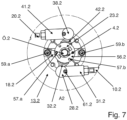
- Fig. 7 shows in a detailed view from the inside the right central axis of rotation 4.2 for the right flap 1.2, namely the area A2 of Fig. 6 .
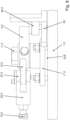
- Fig. 8 shows a detailed view from the inside and parallel to the plane of the right flap 1.2 the right rear locking claw 9.2.
- Fig. 9 shows in a detailed view from the outside and parallel to the plane of the right flap 1.2 the right central axis of rotation 4.2 for the right flap 1.2.
- a right central bracket 13.2 holds the right central pivot axis 4.2 rotatably on the right flap 1.2.
- Several screws 53.1, 53.2, ... are passed through the right flap, cf. Fig. 9 .
- a cross member 18.2 of the central right bracket 13.2 is mounted to the right flap 1.2 in a rotationally fixed manner using the screws 53.1, 53.2, ... In Fig. 1 and in Fig. 9 the heads of these screws 53.1, 53.2, ... can be seen.
- the rotation axis 4.2 is guided through a sleeve 58.2 of the bracket 13.2 and can be rotated about its own central axis relative to the sleeve 58.2.
- This sleeve 58.2 is embedded in the right flap 1.2 and is firmly connected to the inside of the cross member 18.2.
- a disk 60.2 is firmly mounted on the rotation axis 4.2. This disk 60.2 is accommodated in a corresponding recess in the cross member 18.2 and enables rotation of the rotation axis 4.2, but prevents the rotation axis 4.2 from being moved relative to the cross member 18.2 parallel to the central axis of the rotation axis 4.2.
- the two holding elements 62.a and 62.b are firmly connected to the axis of rotation 4.2.
- the stamp 55.2 can not only move linearly relative to the axis of rotation 4.2, but can also rotate around the common central axis.
- the stamp 55.2 can move relative to the two holding elements 62.a and 62.b along its own central axis.
- the stamp 55.2, the holding elements 62.a and 62.b and the lever arm 32.2 can be seen in detail.
- this lever arm 32.2 is connected to a connecting element 31.2 via a joint 28.2, cf. Fig. 7 and Fig. 9
- a screw 61.2 connects the lever arm 32.2 with the joint 28.2 and with the connecting element 32.
- the Connecting element 31.2 is connected to a rod 10.2.
- the distance between connecting element 31.2 and rod 10.2 can be changed using two screws.
- the length of rod 10.2 can be changed.
- a stop element 23.2 with a circular plate can be seen.
- This stop element 23.2 is firmly connected to the cross member 18.2 by means of two screws 59.a, 59.b and prevents the possible rotation of the axis of rotation 4.2 and thus of the lever arm 32.2 relative to the flap 1.2. In one embodiment, this stop element 23.2 also prevents a possible rotation of the piston 55.2.
- two locking pins 57.a and 57.b are mounted on a locking disk 56.2. This locking disk 56.2 is connected in a rotationally fixed manner to the axis of rotation 4.2 and, in one embodiment, also in a rotationally fixed manner to the punch 55.2.
- the stamp 55.2 engages from the inside in the hollow interior of the rotary axis 4.2 and can be moved relative to the rotary axis 4.2 along the common central axis.
- the two holding elements 62.a and 62.b can be moved together with the stamp 55.2 relative to the rotary axis 4.2.
- the stamp 55.2 can be moved linearly relative to the two holding elements 62.a and 62.b.
- the stop element 23.2 limits the movement of the stamp 55.2 away from the opening ⁇ .2.
- a compression spring 54.2 is supported on the rotary axis 4.2 (first embodiment) or on the two holding elements 62.a and 62.b (second embodiment) and strives to move the stamp 55.2 away from the stop element 23.2 into the Fig. 9
- the upper end of the piston 55.2 closes the hexagonal opening ⁇ .2 in the rotation axis 4.2 and prevents water from entering from the outside.
- the piston 55.2 When the piston 55.2 is moved linearly away from the opening ⁇ .2 relative to the axis of rotation 4.2, the opening ⁇ .2 is opened.
- the piston 55.2 is designed as a valve.
- the valve provided by the piston 55.2 compensates for a pressure difference between the inner area, for example of the chamber, which is closed by the flap 1.2, and the outer area outside the flap 1.2. Such a pressure difference can occur, for example, when the underwater vehicle surfaces from a dive and an excess pressure has developed in the chamber.
- the rod 10.2 is connected to another connecting element 25.2, see. Fig. 8 .
- This connecting element 25.2 is connected to a lever arm 12.2 via a joint 27.2.
- the lever arm 12.2 is firmly connected to the locking claw 9.2.
- the lever arm 12.2 and the locking claw 9.2 are mounted so that they can rotate on a pivot axis 11.2.
- An almost triangular plate 17.2 of a bracket 14.2 is mounted so that it cannot rotate on the right-hand flap 1.2 using three screws, whereby these three screws are passed through the right-hand flap 1.2, cf. Fig. 8 .
- the bracket 14.2 holds the rotary axis 11.2.
- the rotary axis 11.2 is guided through a sleeve which is firmly connected to the plate 17.2.
- the transmission means for the rear right locking claw 9.2 include the lever arms 32.2 and 12.2, the connecting elements 31.2 and 25.2 and the rigid rod 10.2.
- the three other locking claws 19.2, 9.1 and 19.1 have corresponding transmission means.
- FIG. 9 describes how the right flap 1.2 is opened.
- a user places an Allen key from the outside on the hexagonal opening ⁇ .2 in the rotary axis 4.2.
- the locking of the rotary axis 4.2 is released.
- the user presses on the Allen key and thereby moves the plunger 55.2 against the force of the spring 54.2 towards the stop element 23.2.
- the punch 55.2 is thereby displaced relative to the rotation axis 4.2 along the longitudinal axis of the rotation axis 4.2. Now the hexagon socket wrench and no longer the punch 55.2 closes the hexagonal opening ⁇ .2.
- the movement of the punch 55.2 causes the locking disk 56.2 with the two pins 57.a and 57.b to also be displaced away from the opening ⁇ .2 (in Fig. 9 downwards) and as a result the two pins 57.a and 57.b no longer engage in the two recesses in the stop element 23.2. This removes the locking of the rotation axis 4.2.
- the disk 60.2 also prevents the rotation axis 4.2 from being displaced relative to the cross member 18.2.
- the punch 55.2 is connected to the rotation axis 4.2 in a rotationally fixed manner and the holding elements 62.a, 62.b are firmly connected to the punch 55.2.
- the rotationally fixed punch 55.2 is rotated with the rotation axis 4.2.
- This also causes the holding elements 62.a and 62.b and thus the lever arms 32.2 and 42.2 (in Fig. 9 not shown).
- the rotation axis 4.2 is firmly connected to the two lever arms 32.2 and 42.2. A rotation of the rotation axis 42.2 is transmitted directly to the two lever arms 32.2 and 42.2.
- this rotation of the lever arms 32.2 and 42.2 is transmitted to the connecting elements 31.2 and 41.2 (in Fig. 9 not shown) and then onto bars 10.2 and 20.2 (in Fig. 9 not shown) and thus transferred to the associated locking claws 9.2 and 19.2.
- the rotation unlocks the flap 1.2.
- the user then removes the Allen key.
- the compression spring 54.2 moves the plunger 55.2 back into the locking position, which is shown in Fig. 9
- the user can turn the unlocked flap 1.2 using the recesses 3.1, 3.2, 3.3 and thereby open it. Later, the user can close the flap 1.2 again and lock it in the corresponding way.
- a third example shows an underwater vehicle according to one of the preceding examples, characterized in that the or each flap in the closed position together with the associated actuating element is flush with the outer hull 2.
- a sixth example shows an underwater vehicle according to example 5, characterized in that the connecting means is articulated both to the lever arm and to the further lever arm.
- a seventh example shows an underwater vehicle according to one of the preceding examples, characterized in that the length of the or at least one transmission means is variable.
- An eighth example shows an underwater vehicle according to one of the preceding examples, characterized in that the actuating element of the or at least one locking device is rotatably mounted and the transmission means of this locking device comprises a lever arm 32.1, 32.2, 42.1, 42.2 which is connected in a rotationally fixed manner to the actuating element.
- a ninth example shows an underwater vehicle according to one of the preceding examples, characterized in that an opening 0.1, ⁇ .2 is let into the or at least one flap and the locking device associated with this flap has a plunger 55.2, wherein the actuating element for this locking device can be actuated through the opening and wherein a spring element 54.2 strives to move the plunger into a closing position in which the plunger closes the opening in the flap.
- a twelfth example shows an underwater vehicle according to example 9 and example 11, characterized in that the spring element for the piston is additionally designed to hold the locking unit in the locking position.
Landscapes
- Engineering & Computer Science (AREA)
- Mechanical Engineering (AREA)
- Chemical & Material Sciences (AREA)
- Combustion & Propulsion (AREA)
- Ocean & Marine Engineering (AREA)
- Aviation & Aerospace Engineering (AREA)
- Lock And Its Accessories (AREA)
Description
Die Erfindung betrifft ein Unterwasserfahrzeug mit einer Klappe und mit einer Arretier-Vorrichtung zum Verriegeln dieser Klappe.The invention relates to an underwater vehicle with a flap and with a locking device for locking this flap.
Aufgabe der Erfindung ist es, ein Unterwasserfahrzeug mit den Merkmalen des Oberbegriffs des Anspruchs 1 bereitzustellen, bei dem die Arretier-Vorrichtung die zugeordnete Klappe sicherer verriegelt und sich leichter betätigen lässt als bei bekannten Unterwasserfahrzeugen.The object of the invention is to provide an underwater vehicle with the features of the preamble of claim 1, in which the locking device locks the associated flap more securely and can be operated more easily than in known underwater vehicles.
Gelöst wird diese Aufgabe durch ein Unterwasserfahrzeug mit den in Anspruch 1 angegebenen Merkmalen. Vorteilhafte Weiterbildungen ergeben sich aus den Unteransprüchen, der nachfolgenden Beschreibung sowie den Zeichnungen.This object is achieved by an underwater vehicle having the features specified in claim 1. Advantageous further developments emerge from the subclaims, the following description and the drawings.
Das erfindungsgemäße Unterwasserfahrzeug umfasst
- eine Außenhülle,
- mindestens eine Klappe und
- jeweils eine Arretier-Vorrichtung für jede Klappe.
- an outer shell,
- at least one flap and
- one locking device for each flap.
Jede Arretier-Vorrichtung umfasst jeweils
- zwei Arretierkörper,
- ein Betätigungselement und
- jeweils ein Übertragungsmittel pro Arretierkörper.
- two locking bodies,
- an actuating element and
- one transmission medium per locking body.
Jedes Übertragungsmittel ist mit dem Betätigungselement und mit dem zugeordneten Arretierkörper mechanisch verbunden.Each transmission means is mechanically connected to the actuating element and to the associated locking body.
Die Außenhülle umschließt einen Innenbereich. Die Außenhülle trennt diesen Innenbereich von einem Außenbereich außerhalb der Außenhülle. Die oder jede Klappe ist mechanisch mit der Außenhülle verbunden und lässt sich relativ zur Außenhülle zwischen einer geschlossenen Position und einer geöffneten Position hin und her bewegen.The outer shell encloses an interior area. The outer shell separates this interior area from an exterior area outside the outer shell. The or each flap is mechanically connected to the outer shell and can be moved back and forth between a closed position and an open position relative to the outer shell.
Bei geschlossener Klappe befinden sich jeder Arretierkörper und jedes Übertragungsmittel im Innenbereich. Das Betätigungselement für diese Klappe lässt sich bei geschlossener Klappe aus dem Außenbereich heraus erreichen.When the flap is closed, each locking element and each transmission device are located inside. The actuating element for this flap can be reached from outside when the flap is closed.
Jeder Arretierkörper lässt sich jeweils zwischen einer Arretier-Position und einer Freigabe-Position hin und her bewegen. Das Betätigungselement lässt sich relativ zu der zugeordneten Klappe bewegen und dadurch betätigen, und zwar aus dem Außenbereich heraus. Jedes mit dem Betätigungselement verbundene Übertragungsmittel überträgt eine Bewegung des Betätigungselements auf den zugeordneten Arretierkörper und bewirkt dadurch, dass der Arretierkörper aus der einen Position in die andere Position bewegt wird. Durch diese bewirkte Bewegung mehrerer Arretierkörper wird die Klappe verriegelt oder entriegelt.Each locking body can be moved back and forth between a locking position and a release position. The actuating element can be moved relative to the associated flap and thus actuated from the outside. Each transmission means connected to the actuating element transfers a movement of the actuating element to the associated locking body and thereby causes the locking body to be moved from one position to the other. The flap is locked or unlocked by this movement of several locking bodies.
Das erfindungsgemäße Unterwasserfahrzeug umfasst eine Außenhülle und mindestens eine Klappe. Die oder jede Klappe ist beweglich in die Außenhülle eingelassen und lässt sich öffnen und wieder schließen. Bei geöffneter Klappe ist ein Zugriff von außen auf den Innenbereich möglich. Beispielsweise ist es möglich, bei geöffneter Klappe Gegenstände in eine Kammer im Innenbereich zu verbringen oder Gegenstände aus dieser Kammer zu entnehmen. Bei geschlossener Klappe schützt die Klappe den Innenbereich, beispielsweise die Kammer, vor Umgebungseinflüssen. Insbesondere ist es möglich, dass die Klappe so ausgestaltet ist, dass der Innenbereich vor dem Eindringen von Wasser geschützt wird. Gegenstände in der Kammer können nicht weggeschwemmt werden. Möglich ist auch, dass sich in der Kammer wenigstens zeitweise ein wasserdichter Behälter befindet, der seinerseits Gegenstände aufnimmt. Die verschlossene und verriegelte Klappe verhindert, dass dieser Behälter fortschwimmt oder beschädigt wird oder sich von alleine öffnet oder unberechtigterweise entnommen wird.The underwater vehicle according to the invention comprises an outer shell and at least one flap. The or each flap is movably embedded in the outer shell and can be opened and closed again. When the flap is open, access to the interior is possible from the outside. For example, when the flap is open, it is possible to move objects into an interior chamber or to remove objects from this chamber. When the flap is closed, the flap protects the interior, for example the chamber, from environmental influences. In particular, it is possible for the flap to be designed in such a way that the interior is protected from the ingress of water. Objects in the chamber cannot be washed away. It is also possible for a watertight container to be located in the chamber at least temporarily, which in turn holds objects. The closed and locked flap prevents this container from floating away or becoming damaged or opening on its own or being removed without authorization.
Die Arretier-Vorrichtung vermag die zugeordnete geschlossene Klappe zu verriegeln und damit zu verhindern, dass sich die geschlossene und verriegelte Klappe unbeabsichtigt öffnet. Dies könnte ohne Arretierung insbesondere dann geschehen, wenn das Unterwasserfahrzeug im Wasser hin und her rollt oder sich anderweitig relativ zum umgebenden Wasser hin und her bewegt oder einer schlagartigen Belastung ausgesetzt ist. Die verriegelte Klappe lässt sich von außen entriegeln.The locking device is able to lock the associated closed flap and thus prevent the closed and locked flap from opening unintentionally. Without the locking device, this could happen in particular if the underwater vehicle rolls back and forth in the water or otherwise moves back and forth relative to the surrounding water or is subjected to a sudden load. The locked flap can be unlocked from the outside.
Die oder jede Arretier-Vorrichtung umfasst jeweils mindestens zwei Arretierkörper. Diese Arretierkörper sind räumlich voneinander beabstandet. Dadurch wird die Klappe an wenigstens zwei Punkten verriegelt, wobei ein Abstand zwischen diesen Punkten auftritt. Verglichen mit einem einzigen Arretierkörper pro Klappe verhindert die Verwendung von mindestens zwei Arretierkörpern weiter die Gefahr, dass die geschlossene und verriegelte Klappe sich unbeabsichtigt öffnet. Selbst wenn ein Arretierkörper aufgrund eines Fehlers nicht in einer Arretier-Position ist, verriegelt der oder mindestens ein anderer Arretierkörper noch die Klappe. Falls die verschlossene Klappe in die Öffnungsrichtung verbogen wird, so ist der dadurch entstehende Spalt zwischen der Klappe und der Außenhülle bei mindestens zwei Arretierkörpern geringer als bei nur einem einzigen Arretierkörper.The or each locking device comprises at least two locking bodies. These locking bodies are spatially spaced from one another. As a result, the flap is locked at at least two points, with a gap occurring between these points. Compared to a single locking body per flap, the use of at least two locking bodies further prevents the risk of the closed and locked flap opening unintentionally. Even if one locking body is not in a locking position due to a fault, the or at least one other locking body still locks the flap. If the closed flap is bent in the opening direction, the resulting gap between the flap and the outer shell is smaller with at least two locking bodies than with just a single locking body.
Lösungsgemäß ist jeder Arretierkörper für die oder eine Klappe über ein Übertragungsmittel mit demselben Betätigungselement verbunden. Durch eine Betätigung dieses einen Betätigungselements lassen sich alle Arretierkörper für diese Klappe quasi mit einem Griff gleichzeitig in die Arretier-Position oder mit einem Griff in die Freigabe-Position verbringen. Nicht erforderlich ist es, dass ein Benutzer nacheinander mehrere Betätigungselemente betätigt, um dieselbe Klappe zu verriegeln oder zu entriegeln. Diese Ausgestaltung spart Zeit ein. Diese Ausgestaltung ist insbesondere dann von Vorteil, wenn die oder eine Klappe bei getauchtem Unterwasserfahrzeug verriegelt oder entriegelt werden soll. Dieser Vorgang erfordert in der Regel, dass ein Taucher zum Unterwasserfahrzeug abtaucht und unter Wasser arbeitet. Die Sicht unter Wasser ist oft wesentlich schlechter als über Wasser oder an Land, und ein Taucher kann sich nur für eine begrenzte Zeitspanne unter Wasser aufhalten. Aus beiden Gründen ist es von Vorteil, nur ein einziges Betätigungselement betätigen zu müssen. Der Taucher braucht nur ein einziges Betätigungselement aufzufinden und zu betätigen, um die oder eine Klappe zu öffnen.According to the solution, each locking body for the flap or a flap is connected to the same actuating element via a transmission means. By actuating this one actuating element, all locking bodies for this flap can be moved to the locking position with one handle or to the release position with one handle. It is not necessary for a user to actuate several actuating elements one after the other to lock or unlock the same flap. This design saves time. This design is particularly advantageous if the flap or a flap is to be locked or unlocked when the underwater vehicle is submerged. This process usually requires a diver to descend to the underwater vehicle and work underwater. Visibility underwater is often much worse than above water or on land, and a diver can only stay underwater for a limited period of time. For both reasons, it is advantageous to only have to actuate a single actuating element. The diver only needs to find and actuate a single actuating element to open the flap or a flap.
Lösungsgemäß ist das Betätigungselement der oder jeder Arretier-Vorrichtung von außen erreichbar. Das heißt, die Arretier-Vorrichtung kann von außen betätigt werden. Daher ist es nicht erforderlich, dass ein Bearbeiter, z.B. ein Taucher, sich in das Innere des Unterwasserfahrzeugs begibt, um den Innenbereich zu erreichen und um beispielsweise Gegenstände in die Kammer zu verbringen oder aus der Kammer zu entnehmen. Das Unterwasserfahrzeug braucht nicht notwendigerweise einen Innenbereich aufzuweisen, in dem ein Mensch sich aufhalten kann.According to the solution, the actuating element of the or each locking device can be reached from the outside. This means that the locking device can be actuated from the outside. It is therefore not necessary for an operator, e.g. a diver, to go inside the underwater vehicle to reach the interior and, for example, to bring objects into the chamber or to remove them from the chamber. The underwater vehicle does not necessarily have to have an interior area in which a person can stay.
Lösungsgemäß sind jeder Arretierkörper und jedes Übertragungsmittel vollständig im Innenbereich angeordnet. Dadurch schützen die Außenhülle und die verschlossene Klappe die Arretierkörper und die Übertragungsmittel vor Umgebungseinflüssen, insbesondere vor dem umgebenden Wasser. Außerdem beeinträchtigt nicht ein Arretierkörper oder ein Übertragungsmittel die hydrodynamische Eigenschaft des Unterwasserfahrzeugs bei der Fahrt über oder unter Wasser, was der Fall sein könnte, wenn ein Arretierkörper oder ein Übertragungsmittel wenigstens teilweise außerhalb des Innenbereichs angeordnet wäre. Insbesondere können kein Arretierkörper und kein Übertragungsmittel eine Verwirbelung im Wasser hervorrufen.According to the solution, each locking body and each transmission means are arranged entirely in the interior. The outer shell and the closed flap therefore protect the locking bodies and the transmission means from environmental influences, in particular from the surrounding water. In addition, no locking body or transmission means impairs the hydrodynamic properties of the underwater vehicle when traveling above or below water, which could be the case if a locking body or transmission means were arranged at least partially outside the interior. In particular, no locking body and no transmission means can cause turbulence in the water.
Bevorzugt bewirkt die Betätigung eines Betätigungselements, dass die mindestens zwei Arretierkörper dieser Arretier-Vorrichtung gleichzeitig aus der einen Position in die andere Position bewegt werden.Preferably, the actuation of an actuating element causes the at least two locking bodies of this locking device to be moved simultaneously from one position to the other position.
Erfindungsgemäß umfasst das Betätigungselement eine Betätigungs-Drehachse. Diese Betätigungs-Drehachse ist durch die zugeordnete Klappe hindurchgeführt. Ein Benutzer kann von außen diese Betätigungs-Drehachse drehen und dadurch die Übertragungsmittel betätigen und die mindestens zwei Arretierkörper, die mit diesem Betätigungselement verbunden sind, bewegen. Die Betätigungs-Drehachse des Betätigungselements ist im Innenbereich mit den beiden Übertragungsmittel mechanisch verbunden. Jedes mit diesem Betätigungselement verbundene Übertragungsmittel kann vollständig im Innenbereich und entlang der Klappe geführt werden. Nicht erforderlich ist es, das Übertragungsmittel entlang einer Kante der Klappe zu führen.According to the invention, the actuating element comprises an actuating axis of rotation. This actuating axis of rotation is guided through the associated flap. A user can rotate this actuating axis of rotation from the outside and thereby actuate the transmission means and move the at least two locking bodies that are connected to this actuating element. The actuating axis of rotation of the actuating element is mechanically connected to the two transmission means in the interior. Each transmission means connected to this actuating element can be guided completely in the interior and along the flap. It is not necessary to guide the transmission means along an edge of the flap.
Vorzugsweise ist in die oder jede Klappe jeweils mindestens eine Aussparung eingelassen. Oder mindestens ein Griff ist an der Klappe angebracht. Mit Hilfe dieser Aussparung oder dieses Griffs kann ein Benutzer, beispielsweise ein Taucher, die entriegelte Klappe relativ zur Außenhülle bewegen und dadurch öffnen. Nicht erforderlich ist, dass der Benutzer ein Werkzeug mitführt, um die entriegelte Klappe zu bewegen.Preferably, at least one recess is provided in the or each flap. Or at least one handle is attached to the flap. With the help of this recess or this handle a user, such as a diver, can move the unlocked flap relative to the outer shell and thereby open it. The user does not need to carry a tool to move the unlocked flap.
Vorzugsweise schließt die oder jede Klappe dann, wenn sie im geschlossenen Zustand ist, bündig mit der Außenhülle ab. Dadurch beeinträchtigt die Klappe nicht die hydrodynamischen Eigenschaften des Unterwasserfahrzeugs und auch nicht eine Signatur des Unterwasserfahrzeugs, also die Erkennbarkeit in einem Radarbild oder einem Sonarbild. Vorzugsweise schließt auch das noch außen zeigende Endstück des Betätigungselements bündig mit der Außenhülle ab, steht also nicht über. Diese Ausgestaltung verbessert weiter die hydrodynamische Eigenschaft des Unterwasserfahrzeugs im Wasser. Bevorzugt ist in die Betätigungs-Drehachse eine Aussparung für einen Innen-Sechskant-Schlüssel eingelassen, wobei diese Aussparung aus dem Außenbereich zugänglich ist. Ein Benutzer kann mit einem handelsüblichen Innen-Sechskant-Schlüssel die Betätigungs-Drehachse drehen und dadurch das Betätigungselement betätigen und die Klappe verriegeln oder entriegeln. Zum Betätigen ist kein spezielles Werkzeug erforderlich.Preferably, the or each flap is flush with the outer hull when it is in the closed state. As a result, the flap does not impair the hydrodynamic properties of the underwater vehicle or a signature of the underwater vehicle, i.e. its recognizability in a radar image or a sonar image. Preferably, the end piece of the actuating element that is still pointing outwards is also flush with the outer hull, i.e. does not protrude. This design further improves the hydrodynamic properties of the underwater vehicle in the water. Preferably, a recess for an Allen key is recessed into the actuating axis of rotation, whereby this recess is accessible from the outside. A user can rotate the actuating axis of rotation with a commercially available Allen key and thereby actuate the actuating element and lock or unlock the flap. No special tool is required for actuation.
In einer Ausgestaltung umfasst das oder mindestens ein Arretierkörper ein Arretierelement und eine Arretierkörper-Drehachse. Das Arretierelement ist fest auf der Arretierkörper-Drehachse montiert. Die Arretierkörper-Drehachse ist drehbar und von innen an der zugeordneten Klappe montiert. In der Arretier-Position greift das Arretierelement wenigstens teilweise unter die Außenhülle, so dass die Außenhülle sich zwischen dem Arretierelement und dem Außenbereich befindet. In der Freigabe-Position überlappt das Arretierelement nicht mit der Außenhülle. Das Übertragungsmittel vermag die Arretierkörper-Drehachse und damit das Arretierelement zu bewegen. Nicht erforderlich ist, dass das Übertragungsmittel direkt mit dem Arretierelement verbunden ist.In one embodiment, the or at least one locking body comprises a locking element and a locking body rotation axis. The locking element is fixedly mounted on the locking body rotation axis. The locking body rotation axis is rotatable and mounted from the inside on the associated flap. In the locking position, the locking element at least partially reaches under the outer shell, so that the outer shell is located between the locking element and the outer area. In the release position, the locking element does not overlap with the outer shell. The transmission means is able to move the locking body rotation axis and thus the locking element. It is not necessary for the transmission means to be directly connected to the locking element.
In einer Ausgestaltung umfasst das oder mindestens ein Übertragungsmittel zwei Hebelarme und ein Verbindungsmittel zwischen diesen beiden Hebelarmen. Der erste Hebelarm ist mit dem Betätigungselement verbunden, im Falle eines drehbaren Betätigungselements drehfest mit der Betätigungs-Drehachse, der andere Hebelarm mit der Arretierkörper-Drehachse. Eine Betätigung des Betätigungselements bewirkt, dass die Betätigungs-Drehachse gedreht wird, der erste Hebelarm an der gedrehten Betätigungs-Drehachse das Verbindungsmittel bewegt und das bewegte Verbindungsmittel die Arretierkörper-Drehachse dreht. Oder der mit dem Betätigungselement verbundene erste Hebelarm wird auf andere Weise bewegt, bewegt das Verbindungsmittel. In beiden Ausgestaltungen bewirkt eine Bewegung des Verbindungsmittels, dass der zweite Hebelarm bewegt wird und das Arretierelement von einer Position in die andere Position gedreht wird.In one embodiment, the or at least one transmission means comprises two lever arms and a connecting means between these two lever arms. The first lever arm is connected to the actuating element, in the case of a rotatable actuating element, in a rotationally fixed manner to the actuating axis of rotation, the other lever arm to the locking body axis of rotation. Actuation of the actuating element causes the actuating axis of rotation to be rotated, the first lever arm on the rotated actuating axis of rotation moves the connecting means and the moved connecting means rotates the locking body axis of rotation. Or the lever arm connected to the If the first lever arm connected to the actuating element is moved in another way, the connecting means moves. In both embodiments, a movement of the connecting means causes the second lever arm to be moved and the locking element to be rotated from one position to the other position.
In einer Ausgestaltung erstreckt sich das Verbindungsmittel entlang einer Längsachse und hat beispielsweise die Form eines Stabs. Bevorzugt lässt sich die Länge dieses Verbindungsmittels verändern, beispielsweise damit jeder Arretierkörper sich ausreichend leicht bewegen lässt und andererseits die Klappe sicher verriegelt und sicher freigibt. Die Möglichkeit, die Länge zu verändern, erleichtert es, die Arretiervorrichtung an verschiedene Umgebungsbedingungen anzupassen, beispielsweise an unterschiedliche Wassertemperaturen oder gewünschte Tauchtiefen.In one embodiment, the connecting means extends along a longitudinal axis and has, for example, the shape of a rod. The length of this connecting means can preferably be changed, for example so that each locking body can be moved easily enough and, on the other hand, the flap is securely locked and released safely. The possibility of changing the length makes it easier to adapt the locking device to different environmental conditions, for example to different water temperatures or desired diving depths.
Erfindungsgemäß ist in die oder eine Klappe eine Öffnung eingelassen. Durch diese Öffnung hindurch kann ein Benutzer mit einem geeigneten Werkzeug das Betätigungselement erreichen. In einer bevorzugten Ausgestaltung wird diese Öffnung automatisch verschlossen, solange der Benutzer nicht das Betätigungselement betätigt. Ein Federelement ist bestrebt, einen Stempel in eine Verschluss-Position zu bewegen. In dieser Verschluss-Position verschließt der Stempel die Öffnung. Der Stempel verhindert somit, dass Wasser durch die Öffnung hindurch in den von der Außenhülle umschlossenen Innenbereich eindringt. Vorzugsweise ist die Federkraft, den das Federelement ausübt, groß genug, damit der Stempel seiner Verschluss-Position bis zu einer bestimmten Tauchtiefe des Unterwasserfahrzeugs beibehalten kann. Dank des Federelements verschließt der Stempel automatisch die Öffnung, ohne dass zum Verschließen ein Benutzereingriff erforderlich ist. Vorzugsweise stützt die Feder sich am Betätigungselement ab.According to the invention, an opening is let into the flap or a flap. A user can reach the actuating element through this opening using a suitable tool. In a preferred embodiment, this opening is automatically closed as long as the user does not actuate the actuating element. A spring element tends to move a plunger into a closed position. In this closed position, the plunger closes the opening. The plunger thus prevents water from penetrating through the opening into the interior area enclosed by the outer shell. Preferably, the spring force exerted by the spring element is large enough for the plunger to maintain its closed position up to a certain diving depth of the underwater vehicle. Thanks to the spring element, the plunger automatically closes the opening without user intervention being required to close it. Preferably, the spring is supported on the actuating element.
Der Stempel lässt sich gegen die Federkraft dieses Federelements bewegen, um die Öffnung freizugeben und um es zu ermöglichen, das Betätigungselement durch die Öffnung hindurch zu bewegen. Vorzugsweise lässt sich der Stempel von außen gegen die Federkraft bewegen, und zwar dadurch, dass ein geeignetes Werkzeug durch die Öffnung hindurch eingeführt und gegen den Stempel gedrückt wird. Diese Ausgestaltung ermöglicht es, dass ein Benutzer, beispielsweise ein Taucher, ein Werkzeug in die Öffnung einführt und zunächst den Stempel gegen die Federkraft aus der Verschluss-Position bewegt und anschließend das Betätigungselement betätigt, ohne zuvor das Werkzeug wieder aus der Öffnung herausziehen zu müssen.The plunger can be moved against the spring force of this spring element to release the opening and to enable the actuating element to be moved through the opening. Preferably, the plunger can be moved from the outside against the spring force by inserting a suitable tool through the opening and pressing it against the plunger. This design enables a user, for example a diver, to insert a tool into the opening and first move the plunger against the spring force from the closed position and then actuate the actuating element without first having to pull the tool out of the opening again.
Erfindungsgemäß stellt dieser Stempel zusätzlich ein Ventil bereit. Mindestens dann, wenn der Stempel gegen die Federkraft von der Öffnung weg bewegt ist, gleicht dieses Ventil eine Druckdifferenz zwischen dem Innenbereich und dem Außenbereich aus. Diese Ausgestaltung vermeidet insbesondere, dass bei einem deutlich höheren Druck im Innenbereich die Druckdifferenz die entriegelte Klappe ruckartig öffnet.According to the invention, this piston also provides a valve. At least when the piston is moved away from the opening against the spring force, this valve compensates for a pressure difference between the inner and outer areas. This design in particular prevents the pressure difference from causing the unlocked flap to open abruptly when the pressure in the inner area is significantly higher.
In einer Ausgestaltung ist das oder mindestens ein Betätigungselement drehbar gelagert. Eine Drehung des Betätigungselements bewirkt, dass jeder Arretierkörper der zugeordneten Arretier-Vorrichtung aus der einen Position in die andere Position bewegt wird. Möglich ist auch, dass das oder mindestens ein Betätigungselement verschiebbar gelagert ist und eine Verschiebung des Betätigungselements bewirkt, dass der zugeordneten Arretierkörper aus der einen Position in die andere Position bewegt wird. In einer Ausgestaltung besitzt jedes Übertragungsmittel jeweils einen Hebelarm. Die mindestens zwei Hebelarme sind drehfest mit dem drehbaren Betätigungselement verbunden.In one embodiment, the or at least one actuating element is mounted so that it can rotate. A rotation of the actuating element causes each locking body of the associated locking device to be moved from one position to the other position. It is also possible for the or at least one actuating element to be mounted so that it can move and a displacement of the actuating element causes the associated locking body to be moved from one position to the other position. In one embodiment, each transmission means has a lever arm. The at least two lever arms are connected in a rotationally fixed manner to the rotatable actuating element.
Die Ausgestaltung mit dem Stempel lässt sich mit der Ausgestaltung mit dem drehbar gelagerten Betätigungselement kombinieren. Vorzugsweise bewegt ein Benutzer dadurch den Stempel von der Öffnung weg, dass ein Werkzeug in die Öffnung eingeführt, und betätigt dann das Betätigungselement, indem er das eingeführte Werkzeug dreht.The design with the stamp can be combined with the design with the rotatably mounted actuating element. Preferably, a user moves the stamp away from the opening by inserting a tool into the opening and then actuates the actuating element by rotating the inserted tool.
In einer Ausführungsform ist das drehbar gelagerte Betätigungselement drehfest mit dem Stempel verbunden. Der Stempel ist mit jedem Übertragungsmittel dieser Arretier-Vorrichtung mechanisch verbunden. Eine Drehung des Betätigungselements bewirkt daher, dass der Stempel mit gedreht wird. Jedes Übertragungsmittel überträgt die Drehung des Stempels auf den zugeordneten Arretierkörper. Diese Ausführungsform ermöglicht eine besonders kompakte Bauweise, insbesondere weil die Drehachse des Betätigungselements mit der Drehachse des Stempel übereinstimmen kann und weil der Stempel zwei Funktionen hat, nämlich zum einen die, die Öffnung abzudichten, und zum anderen die, die Drehung des Betätigungselements auf das Übertragungsmittel zu übertragen. Zwei verschiedene Bauteile sind daher nicht erforderlich. In einer anderen Ausführungsform lässt das Betätigungselement sich relativ zum Stempel drehen.In one embodiment, the rotatably mounted actuating element is connected to the stamp in a rotationally fixed manner. The stamp is mechanically connected to each transmission means of this locking device. A rotation of the actuating element therefore causes the stamp to rotate. Each transmission means transmits the rotation of the stamp to the associated locking body. This embodiment enables a particularly compact design, in particular because the axis of rotation of the actuating element can coincide with the axis of rotation of the stamp and because the stamp has two functions, namely, on the one hand, to seal the opening and, on the other hand, to transmit the rotation of the actuating element to the transmission means. Two different components are therefore not required. In another embodiment, the actuating element can rotate relative to the stamp.
In einer Ausgestaltung besitzt die oder mindestens eine Arretier-Vorrichtung zusätzlich eine Arretiereinheit, die zwischen einer Arretier-Position und einer Freigabe-Position beweglich ist.In one embodiment, the or at least one locking device additionally has a locking unit which is movable between a locking position and a release position.
Diese Arretiereinheit verhindert in der Arretier-Position, dass das Betätigungselement dieser Arretier-Vorrichtung sich ungewollt bewegt und dadurch die zugeordnete Klappe nicht mehr verriegelt ist. Insbesondere verhindert diese Arretiereinheit in der Arretier-Position, dass das Betätigungselement sich ohne Benutzereingriff so bewegt, dass die Arretierkörper dieser Arretier-Vorrichtung in die Freigabeposition bewegt werden oder dass die Bewegung eines Arretierkörpers oder eines Übertragungsmittels eine Bewegung des Betätigungselements und damit eine Bewegung jedes Arretierkörpers in die Freigabe-Position bewirkt.In the locking position, this locking unit prevents the actuating element of this locking device from moving unintentionally and thus the associated flap is no longer locked. In particular, in the locking position, this locking unit prevents the actuating element from moving without user intervention in such a way that the locking bodies of this locking device are moved into the release position or that the movement of a locking body or a transmission means causes a movement of the actuating element and thus a movement of each locking body into the release position.
Die Ausgestaltung mit der Arretiereinheit lässt sich mit der Ausgestaltung, die einen Stempel und ein Federelement vorsieht, kombinieren. In einer Ausführungsform dieser Kombination hat dasselbe Federelement gleichzeitig zwei Funktionen: Zum einen hält das Federelement den Stempel in der Verschluss-Position. Zum anderen hält das Federelement die Arretiereinheit für das Betätigungselement in der Arretier-Position. Diese Ausgestaltung ermöglicht eine besonders kompakte Bauweise und spart gegenüber einer Ausführungsform, bei der zwei verschiedene Elemente den Stempel in der Verschluss-Position und die Arretiereinheit in der Arretier-Position halten. Wenn der Stempel gegen die Federkraft bewegt wird, so wird zugleich die Arretiereinheit in die Freigabe-Position bewegt.The design with the locking unit can be combined with the design that provides a stamp and a spring element. In one embodiment of this combination, the same spring element has two functions at the same time: Firstly, the spring element holds the stamp in the closed position. Secondly, the spring element holds the locking unit for the actuating element in the locked position. This design enables a particularly compact construction and saves space compared to a design in which two different elements hold the stamp in the closed position and the locking unit in the locked position. When the stamp is moved against the spring force, the locking unit is simultaneously moved into the release position.
In einer weiteren Ausführungsform der Erfindung sind mindestens zwei Klappen drehbar in die Außenhülle eingelassen. Vorzugsweise lässt sich jede Klappe unabhängig von der oder jeder anderen Klappe öffnen und schließen. In der geschlossenen Position verriegeln und entriegeln. Dadurch wird es erleichtert, Zugang aus verschiedenen Richtungen zum Innenbereich zu erhalten. Wahlweise lässt sich nur eine Klappe öffnen, und die oder jede andere Klappe bleibt geschlossen und verriegelt, oder beide oder mindestens zwei Klappen werden geöffnet und entriegelt. Dadurch wird es ermöglicht, wahlweise eine kleinere Öffnung oder eine größere Öffnung zum Innenbereich herzustellen. Jeder Klappe ist eine Arretier-Vorrichtung mit jeweils wenigstens zwei Arretierkörpern, zwei Übertragungsmitteln und einem Betätigungselement zugeordnet. Dadurch umfasst das Unterwasserfahrzeug insgesamt wenigstens zwei Betätigungselemente, wenigstens vier Arretierkörper und wenigstens vier Übertragungsmittel.In a further embodiment of the invention, at least two flaps are rotatably embedded in the outer hull. Preferably, each flap can be opened and closed independently of the or any other flap. Locked and unlocked in the closed position. This makes it easier to gain access to the interior from different directions. Optionally, only one flap can be opened and the or any other flap remains closed and locked, or both or at least two flaps are opened and unlocked. This makes it possible to create either a smaller opening or a larger opening to the interior. Each flap is assigned a locking device, each with at least two locking bodies, two transmission means and an actuating element. The underwater vehicle therefore comprises a total of at least two actuating elements, at least four locking bodies and at least four transmission means.
Das Wasserfahrzeug mit der Klappe und der Arretier-Vorrichtung kann ein Überwasserfahrzeug oder ein Unterwasserfahrzeug sein und einen eigenen Antrieb aufweisen oder von einem anderen Fahrzeug durchs Wasser geschleppt werden. Das Wasserfahrzeug kann ein bemanntes oder ein unbemanntes Wasserfahrzeug sein. Die Außenhülle kann zugleich einen Druckkörper des Unterwasserfahrzeugs ausbilden oder aber dem Druckkörper umschließen, wobei der Druckkörper sich im Innenbereich befindet. Die Außenhülle kann auch nur einen Teil des Druckkörpers umschließen. Möglich ist auch, dass das Unterwasserfahrzeug unbemannt ist und keinen Druckkörper aufweist, der einen Innenbereich für Besatzungsmitglieder umschließt. Wenn das Unterwasserfahrzeug sich in einer Schwimmlage über Wasser befindet, so kann die Klappe unterhalb oder oberhalb der Wasserlinie angeordnet sein.The watercraft with the flap and the locking device can be a surface vehicle or an underwater vehicle and can have its own propulsion or be towed through the water by another vehicle. The watercraft can be a manned or unmanned watercraft. The outer hull can also be a pressure hull of the underwater vehicle or enclose the pressure hull, with the pressure hull being located in the interior. The outer shell can also enclose only part of the pressure hull. It is also possible that the underwater vehicle is unmanned and does not have a pressure hull that encloses an interior area for crew members. If the underwater vehicle is in a floating position above water, the flap can be located below or above the waterline.
Nachfolgend ist das erfindungsgemäße Unterwasserfahrzeug anhand eines in den Zeichnungen dargestellten Ausführungsbeispiels näher erläutert. Hierbei zeigen
-
Fig. 1 in einer Betrachtungsrichtung von außen die Außenhülle mit beiden Klappen im geschlossenen Zustand; -
Fig. 2 in einer Querschnittsdarstellung die Außenhülle mit der linken Klappe im geöffneten und der rechten Klappe im geschlossenen Zustand; -
Fig. 3 in einer Betrachtungsrichtung von innen die Außenhülle mit beiden Klappen im geschlossenen Zustand, wobei die linke Klappe arretiert und die rechte Klappe nicht arretiert ist; -
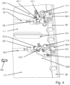
Fig. 4 in einer Betrachtungsrichtung von innen eine Detailsicht der Anordnung vonFig. 3 mit den beiden hinteren Verriegelungs-Klauen; -
Fig. 5 in einer Betrachtungsrichtung von innen die linke Klappe im arretierten Zustand; -
Fig. 6 in einer Betrachtungsrichtung von innen die rechte Klappe im nicht arretierten Zustand; -
Fig. 7 in einer Detailsicht von innen die rechte zentrale Drehachse für die rechte Klappe; -
Fig. 8 in einer Detailsicht von innen und parallel zur Ebene der rechten Klappe die rechte hintere Verriegelungs-Klaue; -
Fig. 9 in einer Querschnittsdarstellung annähernd parallel zur Ebene der rechten Klappe die rechte zentrale Drehachse für die rechte Klappe.
-
Fig. 1 in a viewing direction from the outside, the outer shell with both flaps in the closed state; -
Fig. 2 in a cross-sectional view of the outer shell with the left flap in the open state and the right flap in the closed state; -
Fig. 3 in a viewing direction from the inside, the outer shell with both flaps in the closed state, with the left flap locked and the right flap unlocked; -
Fig. 4 in a viewing direction from the inside a detailed view of the arrangement ofFig. 3 with the two rear locking claws; -
Fig. 5 in a viewing direction from the inside, the left flap in the locked position; -
Fig. 6 in a viewing direction from the inside, the right flap in the unlocked state; -
Fig. 7 in a detailed view from the inside the right central axis of rotation for the right flap; -
Fig. 8 in a detailed view from the inside and parallel to the plane of the right flap, the right rear locking claw; -
Fig. 9 in a cross-sectional view approximately parallel to the plane of the right flap, the right central axis of rotation for the right flap.
Im Ausführungsbeispiel wird die Erfindung eingesetzt, um zwei Klappen zu verriegeln, wobei diese beiden Klappen drehbar in die Außenhülle eines Unterwasserfahrzeugs mit einem Druckkörper eingesetzt sind. Wenn die beiden Klappen geöffnet sind, geben sie den Zugang zu einer Kammer im Innenbereich der Außenhülle frei. Vorzugsweise ist der Druckkörper des Unterwasserfahrzeugs im Innenbereich der Außenhülle angeordnet, und diese Kammer befindet sich zwischen der Außenhülle und dem Innenbereich. Möglich ist auch, dass die Außenhülle nur einen oberen Teil des Druckkörpers umgibt, beispielsweise oben auf den Druckkörper aufgesetzt ist. Wenn die beiden Klappen geschlossen sind, schließen sie bündig mit der übrigen Außenhülle des Unterwasserfahrzeugs ab.In the exemplary embodiment, the invention is used to lock two flaps, these two flaps being rotatably inserted into the outer hull of an underwater vehicle with a pressure hull. When the two flaps are opened, they provide access to a chamber in the inner region of the outer hull. Preferably, the pressure hull of the underwater vehicle is arranged in the inner region of the outer hull, and this chamber is located between the outer hull and the inner region. It is also possible for the outer hull to only surround an upper part of the pressure hull, for example placed on top of the pressure hull. When the two flaps are closed, they are flush with the rest of the underwater vehicle's outer hull.
Im Ausführungsbeispiel lässt sich jede Klappe unabhängig von der anderen Klappe öffnen und schließen. Außerdem lässt sich jede geschlossene Klappe unabhängig von der anderen Klappe wahlweise in einen verriegelten (arretierten) oder in einen nicht verriegelten (nicht arretierten) Zustand überführen. Nur im nicht verriegelten Zustand lässt die Klappe sich öffnen. Indem die geschlossene Klappe in den verriegelten Zustand überführt wird, wird verhindert, dass sie sich ungewollt von alleine öffnet. Im Ausführungsbeispiel sind die beiden Klappen aus glasfaserverstärktem Kunststoff hergestellt, damit ihr Gewicht gering ist und sie sich relativ leicht drehen lassen.In the example, each flap can be opened and closed independently of the other flap. In addition, each closed flap can be switched to a locked (arrested) or unlocked (unlocked) state independently of the other flap. The flap can only be opened when it is not locked. By switching the closed flap to the locked state, it is prevented from opening accidentally on its own. In the example, the two flaps are made of glass fiber reinforced plastic so that they are light and can be rotated relatively easily.
Ein Benutzer kann jede Klappe von dem verriegelten in den nicht verriegelten Zustand überführen und nicht verriegelten Klappe anschließend öffnen, um mindestens einen Gegenstand in die Kammer zu verbringen oder aus der Kammer zu entnehmen. Gewünscht wird, dass die Klappe sich auch dann entriegeln und öffnen lässt, wenn das Unterwasserfahrzeug vollständig getaucht ist, beispielsweise von einem Taucher.A user can move each door from the locked to the unlocked state and then open the unlocked door to insert or remove at least one object into the chamber. It is desirable that the door can be unlocked and opened even when the underwater vehicle is fully submerged, for example by a diver.
Innen an die linke Klappe 1.1 ist ein Verstärkungselement 5.1 montiert, innen an die rechte Klappe 1.2 ein Verstärkungselement 5.2. Die linke Klappe 1.1 ist um eine Drehachse 15.1 relativ zur Außenhülle 2 drehbar, die rechte Klappe 1.2 um eine Drehachse 15.2. Die linke Drehachse 15.1 ist an einem linken Querträger 7.1 montiert, der innen an der Außenhülle 2 befestigt ist und sich annähernd parallel zur Fahrtrichtung FR erstreckt, die rechte Drehachse 15.2 an einem rechten Querträger 7.2. Wenn beide Klappen 1.1 und 1.2 geschlossen sind, so befinden sich die beiden Klappen 1.1 und 1.2 zwischen den beiden Drehachsen 15.1 und 15.2. Zwischen den beiden Klappen 1.1 und 1.2 werden drei ovale Greiföffnungen 3.1, 3.2 und 3.3 ausgebildet, die durch entsprechende Aussparungen in den freien (inneren) Kanten der beiden Klappen 1.1 und 1.2 entstehen. Ein Benutzer kann von außen in eine solche Greiföffnung eingreifen, um eine geschlossene und entriegelte Klappe 1.1 oder 1.2 zu öffnen.A reinforcement element 5.1 is mounted on the inside of the left flap 1.1, and a reinforcement element 5.2 is mounted on the inside of the right flap 1.2. The left flap 1.1 can rotate about a rotation axis 15.1 relative to the
Innen an die Außenhülle 2 ist ein Aufnahmeelement 8 montiert, das bei geschlossener linker Klappe 1.1 das Verstärkungselement 5.1 aufnimmt und bei geschlossener rechter Klappe 1.2 das Verstärkungselement 5.2. An die linke Klappe 1.1 nahe der Drehachse 15.1 sind - gesehen in die Fahrtrichtung FR - eine vordere linke Verschluss-Klaue 16.1 und eine hintere linke Verschluss-Klaue 6.1 montiert. Die vordere linke Verschlussklaue 16.1 wird mit einer Halterung 26.1 an der Klappe 1.1 gehalten, die hintere linke Verschlussklaue 6.1 mit einer Halterung 36.1, vgl.
Eine linke zentrale Drehachse 4.1 ist durch die linke Klappe 1.1 hindurch geführt. Diese linke zentrale Drehachse 4.1 ist etwa mittig zwischen dem - gesehen in die Fahrtrichtung FR - vorderen Ende und dem hinteren Ende der linken Klappe 1.1 angeordnet, und zwar nahe der freien Kante der linken Klappe 1.1 und nahe der Greiföffnung 3.2. Entsprechend ist eine rechte zentrale Drehachse 4.2 durch die rechte Klappe 1.1 hindurch geführt. Ein Benutzer kann von außen ein Werkzeug auf die linke zentrale Drehachse 4.1 aufsetzen und mit Hilfe dieses Werkzeugs die linke zentrale Drehachse 4.1 wahlweise in die eine oder in die andere Richtung drehen. Eine Drehung der linken zentralen Drehachse 4.1 bewirkt, dass die linke Klappe 1.1 vom verriegelten in den nicht verriegelten Zustand überführt wird oder umgekehrt vom nicht verriegelten Zustand in den verriegelten Zustand. Wie dies bewirkt wird, wird weiter unten beschrieben.A left central axis of rotation 4.1 is guided through the left flap 1.1. This left central axis of rotation 4.1 is arranged approximately in the middle between the front end - seen in the direction of travel FR - and the rear end of the left flap 1.1, namely near the free edge of the left flap 1.1 and near the gripping opening 3.2. Accordingly, a right central axis of rotation 4.2 is guided through the right flap 1.1. A user can place a tool on the left central axis of rotation 4.1 from the outside and use this tool to rotate the left central axis of rotation 4.1 in either direction. A rotation of the left central axis of rotation 4.1 causes the left flap 1.1 to be transferred from the locked to the unlocked state or vice versa from the unlocked to the unlocked state. locked state to the locked state. How this is achieved is described below.
In
In
Wenn die Drehachse 11.1 in die eine Richtung gedreht wird (in
Indem ein Benutzer mit Hilfe eines Werkzeugs die linke zentrale Drehachse 4.1 dreht, überführt er die linke Klappe 1.1 von dem verriegelten Zustand in den nicht verriegelten Zustand oder umgekehrt. Diese Drehung der zentralen Drehachse 4.1 bewirkt, dass beide Verriegelungs-Klauen 19.1 und 9.1 gleichzeitig aus der Arretier-Position in die Freigabe-Position oder gleichzeitig aus der Freigabe-Position in die Arretier-Position überführt werden. Jeweils ein Übertragungsmittel pro Verriegelungs-Klaue 19.1 und 9.1 überträgt die Drehung der linken zentralen Drehachse 4.1 synchron auf beide linken Verriegelungs-Klauen 19.1 und 9.1. Entsprechend überträgt jeweils ein Übertragungsmittel pro Verriegelungs-Klaue 19.2 und 9.2 die Drehung der rechten zentralen Drehachse 4.2 synchron auf beide rechten Verriegelungs-Klauen 19.2 und 9.2.By rotating the left central rotary axis 4.1 with the aid of a tool, a user transfers the left flap 1.1 from the locked state to the unlocked state or vice versa. This rotation of the central rotary axis 4.1 causes both locking claws 19.1 and 9.1 to be simultaneously transferred from the locking position to the release position or simultaneously from the release position to the locking position. One transmission means per locking claw 19.1 and 9.1 transfers the rotation of the left central rotary axis 4.1 synchronously to both left locking claws 19.1 and 9.1. Accordingly, one transmission means per locking claw 19.2 and 9.2 transfers the rotation of the right central rotary axis 4.2 synchronously to both right locking claws 19.2 and 9.2.
Das Übertragungsmittel für die hintere rechte Verriegelungs-Klaue 9.2 wird im Folgenden mit Bezug zu
Eine rechte zentrale Halterung 13.2 hält die rechte zentrale Drehachse 4.2 drehbar an der rechten Klappe 1.2. Mehrere Schrauben 53.1, 53.2, ... sind durch die rechte Klappe hindurch geführt, vgl.
Die Drehachse 4.2 ist durch eine Hülse 58.2 der Halterung 13.2 hindurch geführt und kann relativ zur Hülse 58.2 um die eigene Mittelachse gedreht werden. Diese Hülse 58.2 ist in die rechte Klappe 1.2 eingelassen und innen fest mit dem Querträger 18.2 verbunden. Auf die Drehachse 4.2 ist eine Scheibe 60.2 fest montiert. Diese Scheibe 60.2 ist in einer entsprechenden Aussparung des Querträgers 18.2 aufgenommen und ermöglicht eine Drehung der Drehachse 4.2, verhindert aber, dass die Drehachse 4.2 relativ zum Querträger 18.2 parallel zur Mittelachse der Drehachse 4.2 verschoben werden kann.The rotation axis 4.2 is guided through a sleeve 58.2 of the bracket 13.2 and can be rotated about its own central axis relative to the sleeve 58.2. This sleeve 58.2 is embedded in the right flap 1.2 and is firmly connected to the inside of the cross member 18.2. A disk 60.2 is firmly mounted on the rotation axis 4.2. This disk 60.2 is accommodated in a corresponding recess in the cross member 18.2 and enables rotation of the rotation axis 4.2, but prevents the rotation axis 4.2 from being moved relative to the cross member 18.2 parallel to the central axis of the rotation axis 4.2.
Im Folgenden werden mit Bezug auf
In beiden Ausgestaltungen ist dieser Hebelarm 32.2 über ein Gelenk 28.2 gelenkig mit einem Verbindungselement 31.2 verbunden, vgl.
Außerdem ist in
Der Stempel 55.2 greift von innen in das hohle Innere der Drehachse 4.2 ein und kann relativ zur Drehachse 4.2 entlang der gemeinsamen Mittelachse verschoben werden. In der ersten Ausgestaltung lassen sich die beiden Halteelemente 62.a und 62.b gemeinsam mit dem Stempel 55.2 relativ zur Drehachse 4.2 verschieben. In der zweiten Ausgestaltung lässt sich der Stempel 55.2 relativ zu den beiden Halteelementen 62.a und 62.b linear verschieben. Das Anschlagelement 23.2 begrenzt in beiden Ausgestaltungen die Bewegung des Stempels 55.2 weg von der Öffnung Ö.2. Eine Druckfeder 54.2 stützt sich an der Drehachse 4.2 (erste Ausgestaltung) oder an den beiden Halteelementen 62.a und 62.b (zweite Ausgestaltung) ab und ist bestrebt, den Stempel 55.2 von dem Anschlagelement 23.2 weg in die in
Wenn der Stempel 55.2 relativ zur Drehachse 4.2 linear von der Öffnung Ö.2 weg verschoben wird, ist die Öffnung Ö.2 geöffnet. In einer Ausführungsform ist der Stempel 55.2 als ein Ventil ausgestaltet. Wenn der Stempel 55.2 weg geschoben ist, so gleicht das vom Stempel 55.2 bereitgestellte Ventil eine Druckdifferenz zwischen dem Innenbereich, beispielsweise von der Kammer, der von der Klappe 1.2 verschlossen wird, und dem Außenbereich außerhalb der Klappe 1.2 aus. Eine solche Druckdifferenz kann beispielsweise auftreten, wenn das Unterwasserfahrzeug einer Tauchfahrt auftaucht und in der Kammer ein Überdruck entstanden ist.When the piston 55.2 is moved linearly away from the opening Ö.2 relative to the axis of rotation 4.2, the opening Ö.2 is opened. In one embodiment, the piston 55.2 is designed as a valve. When the piston 55.2 is moved away, the valve provided by the piston 55.2 compensates for a pressure difference between the inner area, for example of the chamber, which is closed by the flap 1.2, and the outer area outside the flap 1.2. Such a pressure difference can occur, for example, when the underwater vehicle surfaces from a dive and an excess pressure has developed in the chamber.
Wenn der Stempel 55.2 weg von der Öffnung Ö.2 verschoben wird, so bewirkt diese Bewegung außerdem, dass der Stempel 55.2 die Sicherungsscheibe 56.2 weg von der Öffnung Ö.2 bewegt. Dies wiederum bewirkt, dass die beiden Sperrzapfen 57.a und 57.b nicht mehr in die beiden Aussparungen des Anschlagelements 23.2 eingreifen, also die Arretiereinheit für die Drehachse 4.2 in einer Freigabe-Position ist.If the punch 55.2 is moved away from the opening Ö.2, this movement also causes the punch 55.2 to move the locking disk 56.2 away from the opening Ö.2. This in turn causes the two locking pins 57.a and 57.b to no longer engage in the two recesses of the stop element 23.2, i.e. the locking unit for the rotary axis 4.2 is in a release position.
Die Stange 10.2 ist mit einem weiteren Verbindungselement 25.2 verbunden, vgl.
Zum Übertragungsmittel für die hintere rechte Verriegelungs-Klaue 9.2 gehören die Hebelarme 32.2 und 12.2, die Verbindungselemente 31.2 und 25.2 sowie die starre Stange 10.2. Die drei anderen Verriegelungs-Klauen 19.2, 9.1 und 19.1 haben entsprechende Übertragungsmittel.The transmission means for the rear right locking claw 9.2 include the lever arms 32.2 and 12.2, the connecting elements 31.2 and 25.2 and the rigid rod 10.2. The three other locking claws 19.2, 9.1 and 19.1 have corresponding transmission means.
Im Folgenden wird beispielhaft und mit Bezug auf
Der Stempel 55.2 wird dadurch relativ zur Drehachse 4.2 entlang der Längsachse der Drehachse 4.2 verschoben. Nunmehr verschließt der Innen-Sechskant-Schlüssel und nicht mehr der Stempel 55.2 die sechseckige Öffnung Ö.2. Die Bewegung des Stempels 55.2 bewirkt, dass die Sicherungsscheibe 56.2 mit den beiden Stiften 57.a und 57.b ebenfalls von der Öffnung Ö.2 weg verschoben wird (in
Nunmehr dreht der Benutzer den eingeschobenen Innen-Sechskant-Schlüssel. Dadurch wird die Drehachse 4.2 relativ zur Hülse 58.2 und damit auch relativ zum Querträger 18.2 um die eigene Mittelachse gedreht. In der ersten Ausgestaltung ist der Stempel 55.2 drehfest mit der Drehachse 4.2 verbunden, und die Halteelemente 62.a, 62.b sind fest mit dem Stempel 55.2 verbunden. Der drehfest verbundene Stempel 55.2 wird mit der Drehachse 4.2 mit gedreht. Dadurch werden auch die Halteelemente 62.a und 62.b und damit die Hebelarme 32.2 und 42.2 (in
In beiden Ausgestaltungen wird diese Drehung der Hebelarme 32.2 und 42.2 auf die Verbindungselemente 31.2 und 41.2 (in
Ferner sind folgende Beispiele offenbart:
Ein erstes Beispiel zeigt ein Unterwasserfahrzeug mit einer Außenhülle 2,mindestens einer mit der Außenhülle verbundenen Klappe 1.1, 1.2 und jeweils einer Arretier-Vorrichtung für jede verbundene Klappe 1.1, 1.2, wobei die oder jede mit der Außenhülle verbundene Klappe 1.1, 1.2 relativ zu der Außenhülle zwischen einer geschlossenen Position und einer geöffneten Position hin und her beweglich ist, wobei die Außenhülle einen Innenbereich umschließt und diesen von einem Außenbereich trennt und wobei die oder jede Arretier-Vorrichtung dazu ausgestaltet ist, die zugeordnete und in der geschlossenen Position befindliche Klappe 1.1, 1.2 zu verriegeln, dadurch gekennzeichnet, dass die oder jede Arretier-Vorrichtung jeweils
- mindestens zwei Arretierkörper 9.1, 11.1, 14.1 und 19.1, 21.1, 24.1 und 9.2, 11.2, 14.2 und 19.2, 21.2, 24.2,
- ein beweglich gelagertes Betätigungselement 4.1, 13.1 und 4.2, 13.2 und
- jeweils ein Übertragungsmittel 32.1, 31.1, 10.1, 25.1, 12.1 und 42.1, 41.1, 20.1, 35.1, 22.1 und 32.2, 31.2, 10.2, 25.2, 12.2, 55.2 und 42.2, 41.2, 20.2, 35.2, 22.2 pro Arretierkörper umfasst, wobei jeder Arretierkörper und jedes Übertragungsmittel sich bei geschlossener Klappe im Innenbereich befinden, wobei das Betätigungselement bei geschlossener Klappe aus dem Außenbereich erreichbar ist, wobei jeder Arretierkörper relativ zur zugeordneten Klappe zwischen einer Arretier-Position und einer Freigabe-Position hin und her beweglich ist, wobei jedes Übertragungsmittel mit dem oder einem zugeordneten Betätigungselement und mit dem zugeordneten Arretierkörper mechanisch verbunden ist und wobei das Übertragungsmittel der oder jeder Arretier-Vorrichtung so angeordnet ist, dass eine Betätigung des Betätigungselements eine Bewegung jedes Arretierkörpers dieser Arretier-Vorrichtung aus der einen Position in die andere Position bewirkt.
A first example shows an underwater vehicle with an
- at least two locking bodies 9.1, 11.1, 14.1 and 19.1, 21.1, 24.1 and 9.2, 11.2, 14.2 and 19.2, 21.2, 24.2,
- a movably mounted actuating element 4.1, 13.1 and 4.2, 13.2 and
- each comprises a transmission means 32.1, 31.1, 10.1, 25.1, 12.1 and 42.1, 41.1, 20.1, 35.1, 22.1 and 32.2, 31.2, 10.2, 25.2, 12.2, 55.2 and 42.2, 41.2, 20.2, 35.2, 22.2 per locking body, wherein each locking body and each transmission means are located in the interior when the flap is closed, wherein the actuating element is accessible from the exterior when the flap is closed, wherein each locking body is movable back and forth relative to the associated flap between a locking position and a release position, wherein each transmission means is mechanically connected to the or an associated actuating element and to the associated locking body, and wherein the transmission means of the or each Locking device is arranged such that actuation of the actuating element causes movement of each locking body of this locking device from one position to the other position.
Ein zweites Beispiel zeigt ein Unterwasserfahrzeug nach Beispiel 1, dadurch gekennzeichnet, dass das oder mindestens ein Betätigungselement 4.1, 13.1 und 4.2, 13.2 eine drehbar gelagerte Betätigungs-Drehachse 4.1, 4.2 umfasst, wobei die Betätigungs-Drehachse 4.1, 4.2
- relativ zu der zugeordneten Klappe drehbar ist und
- durch die Klappe hindurch geführt ist.
- is rotatable relative to the associated flap and
- is passed through the flap.
Ein drittes Beispiel zeigt ein Unterwasserfahrzeug nach einem der vorstehenden Beispiele, dadurch gekennzeichnet, dass die oder jede in der geschlossenen Position befindlichen Klappe mitsamt dem zugeordneten Betätigungselement bündig mit der Außenhülle 2 abschließt.A third example shows an underwater vehicle according to one of the preceding examples, characterized in that the or each flap in the closed position together with the associated actuating element is flush with the
Ein viertes Beispiel zeigt ein Unterwasserfahrzeug nach einem der vorstehenden Beispiele, dadurch gekennzeichnet, dass mindestens ein Arretierkörper
- eine Arretierkörper-Drehachse 11.1, 11.2, 21.1, 21.2 sowie
- ein fest mit der Arretierkörper-Drehachse verbundenes Arretierelement 9.1, 9.2, 19.1, 19.2
umfasst, wobei die Arretierkörper-Drehachse - drehbar an der zugeordneten Klappe befestigt ist und
- sich vollständig im Innenbereich befindet und
wobei das Arretierelement - zwischen der Freigabe-Position und der Arretier-Position beweglich ist und
- in der Arretier-Position von innen unter die Außenhülle greift.
- a locking body rotation axis 11.1, 11.2, 21.1, 21.2 and
- a locking element 9.1, 9.2, 19.1, 19.2 firmly connected to the locking body rotation axis
wherein the locking body rotation axis - is rotatably attached to the associated flap and
- is completely indoors and
whereby the locking element - is movable between the release position and the locking position and
- in the locked position, it reaches under the outer shell from the inside.
Ein fünftes Beispiel zeigt ein Unterwasserfahrzeug nach einem der vorstehenden Beispiele, dadurch gekennzeichnet, dass das oder mindestens ein Übertragungsmittel
- einen Hebelarm 32.1, 32.2, 42.1, 42.2, der mechanisch mit dem Betätigungselement verbunden ist,
- einen weiteren Hebelarm 12.1, 12.2, 22.1, 22.2, der mechanisch mit dem zugeordneten Arretierkörper verbunden ist, sowie
- ein Verbindungsmittel 25.1, 10.1, 31.1 und 25.2, 10.2, 31.2 und 35.1, 20.1, 41.1 und 35.2, 20.2, 41.2 zwischen diesen beiden Hebelarmen
umfasst.
- a lever arm 32.1, 32.2, 42.1, 42.2, which is mechanically connected to the actuating element,
- another lever arm 12.1, 12.2, 22.1, 22.2, which is mechanically connected to the associated locking body, and
- a connecting means 25.1, 10.1, 31.1 and 25.2, 10.2, 31.2 and 35.1, 20.1, 41.1 and 35.2, 20.2, 41.2 between these two lever arms
includes.
Ein sechstes Beispiel zeigt ein Unterwasserfahrzeug nach Beispiel 5, dadurch gekennzeichnet, dass das Verbindungsmittel sowohl mit dem Hebelarm als auch mit dem weiteren Hebelarm gelenkig verbunden ist.A sixth example shows an underwater vehicle according to example 5, characterized in that the connecting means is articulated both to the lever arm and to the further lever arm.
Ein siebtes Beispiel zeigt ein Unterwasserfahrzeug nach einem der vorstehenden Beispiele, dadurch gekennzeichnet, dass die Länge des oder mindestens eines Übertragungsmittels veränderbar ist.A seventh example shows an underwater vehicle according to one of the preceding examples, characterized in that the length of the or at least one transmission means is variable.
Ein achtes Beispiel zeigt ein Unterwasserfahrzeug nach einem der vorstehenden Beispiele, dadurch gekennzeichnet, dass das Betätigungselement der oder mindestens einer Arretier-Vorrichtung drehbar gelagert ist und das Übertragungsmittel dieser Arretier-Vorrichtung einen Hebelarm 32.1, 32.2, 42.1, 42.2 umfasst, welcher drehfest mit dem Betätigungselement verbunden ist.An eighth example shows an underwater vehicle according to one of the preceding examples, characterized in that the actuating element of the or at least one locking device is rotatably mounted and the transmission means of this locking device comprises a lever arm 32.1, 32.2, 42.1, 42.2 which is connected in a rotationally fixed manner to the actuating element.
Ein neuntes Beispiel zeigt ein Unterwasserfahrzeug nach einem der vorstehenden Beispiele, dadurch gekennzeichnet, dass in die oder mindestens eine Klappe eine Öffnung 0.1, Ö.2 eingelassen ist und die dieser Klappe zugeordnete Arretier-Vorrichtung einen Stempel 55.2 aufweist, wobei das Betätigungselement für diese Arretier-Vorrichtung durch die Öffnung hindurch betätigbar ist und wobei ein Federelement 54.2 bestrebt ist, den Stempel in eine Verschluss-Position zu bewegen, in welcher der Stempel die Öffnung in der Klappe verschließt.A ninth example shows an underwater vehicle according to one of the preceding examples, characterized in that an opening 0.1, Ö.2 is let into the or at least one flap and the locking device associated with this flap has a plunger 55.2, wherein the actuating element for this locking device can be actuated through the opening and wherein a spring element 54.2 strives to move the plunger into a closing position in which the plunger closes the opening in the flap.
Ein zehntes Beispiel zeigt ein Unterwasserfahrzeug nach Beispiel 9, dadurch gekennzeichnet, dass das Übertragungsmittel der dieser Klappe zugeordneten Arretier-Vorrichtung einen Hebelarm 32.1, 32.2, 42.1, 42.2 umfasst, der mit dem Stempel mechanisch verbunden ist, und das Betätigungselement
- drehbar gelagert ist und
- drehfest mit dem Stempel verbunden ist.
- is rotatably mounted and
- is non-rotatably connected to the stamp.
Ein elftes Beispiel zeigt ein Unterwasserfahrzeug nach einem der vorstehenden Beispiele, dadurch gekennzeichnet, dass die oder mindestens eine Arretier-Vorrichtung zusätzlich eine Arretiereinheit 56.2, 57.a, 57.b, 54.2 für das Betätigungselement umfasst, wobei die Arretiereinheit dazu ausgestaltet ist,
- in einer Arretier-Position eine Bewegung des Betätigungselements relativ zur zugeordneten Klappe zu verhindern und
- in einer Freigabe-Position eine solche Bewegung zu ermöglichen.
- to prevent movement of the actuating element relative to the associated flap in a locking position and
- in a release position to enable such a movement.
Ein zwölftes Beispiel zeigt ein Unterwasserfahrzeug nach Beispiel 9 und nach Beispiel 11, dadurch gekennzeichnet, dass das Federelement für den Stempel zusätzlich dazu ausgestaltet ist, die Arretiereinheit in der Arretier-Position zu halten.A twelfth example shows an underwater vehicle according to example 9 and example 11, characterized in that the spring element for the piston is additionally designed to hold the locking unit in the locking position.
Ein dreizehntes Beispiel zeigt ein Unterwasserfahrzeug nach einem der vorstehenden Beispiele, dadurch gekennzeichnet, dass das Unterwasserfahrzeug
- mindestens zwei Klappen 1.1, 1.2, die beide drehbar mit der Außenhülle verbunden sind, und
- jeweils eine Arretier-Vorrichtung für jede Klappe umfasst, so dass das Unterwasserfahrzeug insgesamt wenigstens
- vier Arretierkörper,
- vier Übertragungsmittel und
- zwei Betätigungselemente
umfasst.
- at least two flaps 1.1, 1.2, both of which are pivotally connected to the outer shell, and
- one locking device for each flap, so that the underwater vehicle as a whole has at least
- four locking bodies,
- four transmission media and
- two actuators
includes.
Claims (11)
- Underwater vehicle with- an outer hull (2),- a flap (1.1, 1.2) connected to the outer hull, and- a locking device for the flap (1.1, 1.2),wherein the flap (1.1, 1.2) is movable back and forth between a closed position and an open position,wherein the outer cover encloses an inner region and separates this from an outer region, andwherein the locking device is designed to lock the flap (1.1, 1.2) in the closed position, whereinthe locking device- at least two locking bodies (9.1, 11.1, 14.1 and 19.1, 21.1, 24.1 and 9.2, 11.2, 14.2 and 19.2, 21.2, 24.2),- a movably mounted actuating element (4.1, 13.1 and 4.2, 13.2) and- one transmission means (32.1, 31.1, 10.1, 25.1, 12.1 and 42.1, 41.1, 20.1, 35.1, 22.1 and 32.2, 31.2, 10.2, 25.2, 12.2, 55.2 and 42.2, 41.2, 20.2, 35.2, 22.2) per locking body respectivelycomprises,wherein the locking bodies and the transmission means are located in the inner area when the flap is closed,wherein the actuating element can be reached from the outer area when the flap is closed,wherein the locking bodies are movable back and forth relative to the flap between a locking position and a release position,wherein the transmission means are mechanically connected to the actuating element and to the associated locking body, andwherein the transmission means of the locking device is arranged in such a way that an actuation of the actuating element causes a movement of the locking bodies between the locking position and the release position;whereinthe actuating element (4.1, 13.1 and 4.2, 13.2) comprises a rotatably mounted actuating axis of rotation (4.1, 4.2),wherein the actuating axis of rotation (4.1, 4.2)- is rotatable relative to the associated flap and- is guided through the flap;
characterised in thatan opening is recessed in the flap, a spring element being designed to move a plunger into a closed position, so that the opening is automatically closed by means of the plunger if the actuating element is not actuated;wherein the plunger can be moved against the spring force of the spring element to release the opening and move the actuating element through the opening;wherein the plunger provides a valve to equalise a pressure differential between the inner region and the outer region when the plunger is moved away from the opening against the spring force. - Underwater vehicle according to any of the preceding claims,
characterised in that
the flap in the closed position, together with the associated actuating element, is flush with the outer shell (2). - Underwater vehicle according to one of the preceding claims,
characterised in that
at least one locking body- a locking body axis of rotation (11.1, 11.2, 21.1, 21.2) and- a locking element (9.1, 9.2, 19.1, 19.2) firmly connected to the axis of rotation of the locking bodycompriseswherein the locking body axis of rotation- rotatably attached to the associated flap and- is located completely in the inner area and
wherein the locking element- is movable between the release position and the locking position and- engages under the outer shell from the inside in the locking position. - Underwater vehicle according to one of the preceding claims,
characterised in that
the transmission means- a lever arm (32.1, 32.2, 42.1, 42.2) which is mechanically connected to the actuating element,- a further lever arm (12.1, 12.2, 22.1, 22.2), which is mechanically connected to the associated locking body, and- a connecting means (25.1, 10.1, 31.1 and 25.2, 10.2, 31.2 and 35.1, 20.1, 41.1 and 35.2, 20.2, 41.2) between these two lever arms - Underwater vehicle according to claim 4,
characterised in that
the connecting means is articulated both to the lever arm and to the further lever arm. - Underwater vehicle according to one of the preceding claims,
characterised in that
the length of the transmission means is variable. - Underwater vehicle according to one of the preceding claims,
characterised in thatthe actuating element of the locking device is rotatably mounted andthe transmission means of this locking device comprises a lever arm (32.1, 32.2, 42.1, 42.2) which is non-rotatably connected to the actuating element. - Underwater vehicle according to claim 7,
characterised in thatthe transmission means comprises the one lever arm (32.1, 32.2, 42.1, 42.2) which is mechanically connected to the plunger, andthe actuating element- is rotatably mounted and- is non-rotatably connected to the plunger. - Underwater vehicle according to one of the preceding claims,
characterised in thatthe locking device additionally comprises a locking unit (56.2, 57.a, 57.b, 54.2) for the actuating element,wherein the locking unit is designed for this purpose,- preventing movement of the actuating element relative to the associated flap in a locking position and- enabling such a movement in a release position. - Underwater vehicle according to one of claims 7 to 9,
characterised in that
the spring element for the plunger is additionally designed to hold the locking unit in the locking position. - Underwater vehicle according to one of the preceding claims,
characterised in thatthe underwater vehicle- at least two flaps (1.1, 1.2), both of which are rotatably connected to the outer shell, and- a locking device for each flapfor each flap,so that the underwater vehicle comprises a total of at least- four locking bodies,- four transmission means and- two actuating elements.
Applications Claiming Priority (1)
| Application Number | Priority Date | Filing Date | Title |
|---|---|---|---|
| DE102018205487.8A DE102018205487A1 (en) | 2018-04-11 | 2018-04-11 | Underwater vehicle with a lockable flap |
Publications (2)
| Publication Number | Publication Date |
|---|---|
| EP3552945A1 EP3552945A1 (en) | 2019-10-16 |
| EP3552945B1 true EP3552945B1 (en) | 2024-12-04 |
Family
ID=66102863
Family Applications (1)
| Application Number | Title | Priority Date | Filing Date |
|---|---|---|---|
| EP19166966.2A Active EP3552945B1 (en) | 2018-04-11 | 2019-04-03 | Underwater vehicle comprising a lockable flap |
Country Status (2)
| Country | Link |
|---|---|
| EP (1) | EP3552945B1 (en) |
| DE (1) | DE102018205487A1 (en) |
Families Citing this family (1)
| Publication number | Priority date | Publication date | Assignee | Title |
|---|---|---|---|---|
| CN110884613B (en) * | 2019-11-28 | 2021-05-11 | 中国科学院沈阳自动化研究所 | A hatch system of an underwater robot |
Citations (1)
| Publication number | Priority date | Publication date | Assignee | Title |
|---|---|---|---|---|
| DE202006004805U1 (en) * | 2006-03-25 | 2006-06-08 | Howaldtswerke-Deutsche Werft Gmbh | Submarine has locking device by which cover over opening is fixed on outer skin with positive locking, whereby locking device is functionally connected to handle accessible from outer side of skin and provided at least for unlocking |
Family Cites Families (3)
| Publication number | Priority date | Publication date | Assignee | Title |
|---|---|---|---|---|
| US3051280A (en) * | 1958-04-04 | 1962-08-28 | Boeing Co | Outward-opening plug type door for aircraft |
| DE102007041724B4 (en) * | 2007-09-04 | 2017-11-23 | Thyssenkrupp Marine Systems Gmbh | Submarine with an outside arranged vessel |
| CN201834177U (en) * | 2010-08-26 | 2011-05-18 | 无锡市东舟船舶附件有限公司 | A60-class quick opening and closing fire-proof and watertight hatch cover |
-
2018
- 2018-04-11 DE DE102018205487.8A patent/DE102018205487A1/en not_active Withdrawn
-
2019
- 2019-04-03 EP EP19166966.2A patent/EP3552945B1/en active Active
Patent Citations (1)
| Publication number | Priority date | Publication date | Assignee | Title |
|---|---|---|---|---|
| DE202006004805U1 (en) * | 2006-03-25 | 2006-06-08 | Howaldtswerke-Deutsche Werft Gmbh | Submarine has locking device by which cover over opening is fixed on outer skin with positive locking, whereby locking device is functionally connected to handle accessible from outer side of skin and provided at least for unlocking |
Also Published As
| Publication number | Publication date |
|---|---|
| EP3552945A1 (en) | 2019-10-16 |
| DE102018205487A1 (en) | 2019-10-17 |
Similar Documents
| Publication | Publication Date | Title |
|---|---|---|
| DE60109697T2 (en) | Motor vehicle with independent pivoting and sliding doors | |
| EP3234289B1 (en) | Actuator for a switchboard cabinet door | |
| DE3539480A1 (en) | OPERATING DEVICE FOR A FREIGHT LOADING GATE | |
| DE202014102405U1 (en) | Locking device for sliding doors of public transport vehicles; Sliding sliding door with locking device | |
| DE102013222955A1 (en) | Double hood lock arrangement | |
| DE102012010786A1 (en) | Panic lock with selection device in the lock case | |
| DE202015101373U1 (en) | Vehicle with divided tailgate | |
| EP2572415B1 (en) | Door assembly for an instrument cabinet and method for changing a stop side of a door assembly | |
| DE202009007141U1 (en) | Watercraft with a platform lift | |
| EP2094924A2 (en) | Door lock for doors of aircraft, especially of helicopters | |
| EP0398106B1 (en) | Operating device for pivoted and/or sliding car body parts of motor vehicles | |
| DE10128866A1 (en) | Grab handle for a vehicle tailgate or boot comprises swivel grip plate which moves from rest position covering grip trough to protruding operating position about a swivel axis running in centre areas | |
| EP3552945A1 (en) | Underwater vehicle comprising a lockable flap | |
| EP2016245A1 (en) | Closing device | |
| DE102008064374B3 (en) | Opening and closing device of a top compartment lid | |
| DE3915737A1 (en) | DEVICE FOR ACTUATING SWIVELING AND / OR SLIDING BODY PARTS ON MOTOR VEHICLES | |
| DE3608369C2 (en) | ||
| EP2927514B1 (en) | Covering of a holder opening of a holder compartment | |
| EP3287579B1 (en) | Closure device for a door | |
| DE102005061127A1 (en) | Aircraft door arrangement has door structure that can be lifted from locked closed position to unlocked closed position and can be pivoted from there into open position outside door frame and fuselage; it has cover element for door gap | |
| DE20017674U1 (en) | Detachable mechanical locking arrangement between a pivotable lid and a container, preferably a luggage compartment | |
| EP2499315B1 (en) | Motor vehicle door latch | |
| DE102005030705B4 (en) | Fuel tank hatch for motor vehicles | |
| EP3269902B1 (en) | Operating assembly for a building closure, corresponding building closure, kit for the preparation of building closures and method of equipping a building closure | |
| DE2918837A1 (en) | Emergency release for central locking systems - has cylinder lock-operated lever shifting blocking element out of engagement |
Legal Events
| Date | Code | Title | Description |
|---|---|---|---|
| PUAI | Public reference made under article 153(3) epc to a published international application that has entered the european phase |
Free format text: ORIGINAL CODE: 0009012 |
|
| STAA | Information on the status of an ep patent application or granted ep patent |
Free format text: STATUS: THE APPLICATION HAS BEEN PUBLISHED |
|
| AK | Designated contracting states |
Kind code of ref document: A1 Designated state(s): AL AT BE BG CH CY CZ DE DK EE ES FI FR GB GR HR HU IE IS IT LI LT LU LV MC MK MT NL NO PL PT RO RS SE SI SK SM TR |
|
| AX | Request for extension of the european patent |
Extension state: BA ME |
|
| STAA | Information on the status of an ep patent application or granted ep patent |
Free format text: STATUS: REQUEST FOR EXAMINATION WAS MADE |
|
| 17P | Request for examination filed |
Effective date: 20200416 |
|
| RBV | Designated contracting states (corrected) |
Designated state(s): AL AT BE BG CH CY CZ DE DK EE ES FI FR GB GR HR HU IE IS IT LI LT LU LV MC MK MT NL NO PL PT RO RS SE SI SK SM TR |
|
| RAP1 | Party data changed (applicant data changed or rights of an application transferred) |
Owner name: THYSSENKRUPP MARINE SYSTEMS GMBH Owner name: THYSSENKRUPP AG |
|
| STAA | Information on the status of an ep patent application or granted ep patent |
Free format text: STATUS: EXAMINATION IS IN PROGRESS |
|
| 17Q | First examination report despatched |
Effective date: 20211011 |
|
| 17Q | First examination report despatched |
Effective date: 20211022 |
|
| GRAP | Despatch of communication of intention to grant a patent |
Free format text: ORIGINAL CODE: EPIDOSNIGR1 |
|
| STAA | Information on the status of an ep patent application or granted ep patent |
Free format text: STATUS: GRANT OF PATENT IS INTENDED |
|
| INTG | Intention to grant announced |
Effective date: 20240705 |
|
| GRAS | Grant fee paid |
Free format text: ORIGINAL CODE: EPIDOSNIGR3 |
|
| GRAA | (expected) grant |
Free format text: ORIGINAL CODE: 0009210 |
|
| STAA | Information on the status of an ep patent application or granted ep patent |
Free format text: STATUS: THE PATENT HAS BEEN GRANTED |
|
| AK | Designated contracting states |
Kind code of ref document: B1 Designated state(s): AL AT BE BG CH CY CZ DE DK EE ES FI FR GB GR HR HU IE IS IT LI LT LU LV MC MK MT NL NO PL PT RO RS SE SI SK SM TR |
|
| REG | Reference to a national code |
Ref country code: GB Ref legal event code: FG4D Free format text: NOT ENGLISH |
|
| REG | Reference to a national code |
Ref country code: CH Ref legal event code: EP |
|
| REG | Reference to a national code |
Ref country code: DE Ref legal event code: R096 Ref document number: 502019012576 Country of ref document: DE |
|
| REG | Reference to a national code |
Ref country code: IE Ref legal event code: FG4D Free format text: LANGUAGE OF EP DOCUMENT: GERMAN |
|
| REG | Reference to a national code |
Ref country code: DE Ref legal event code: R084 Ref document number: 502019012576 Country of ref document: DE |
|
| REG | Reference to a national code |
Ref country code: LT Ref legal event code: MG9D |
|
| REG | Reference to a national code |
Ref country code: NL Ref legal event code: MP Effective date: 20241204 |
|
| PG25 | Lapsed in a contracting state [announced via postgrant information from national office to epo] |
Ref country code: HR Free format text: LAPSE BECAUSE OF FAILURE TO SUBMIT A TRANSLATION OF THE DESCRIPTION OR TO PAY THE FEE WITHIN THE PRESCRIBED TIME-LIMIT Effective date: 20241204 |
|
| PG25 | Lapsed in a contracting state [announced via postgrant information from national office to epo] |
Ref country code: FI Free format text: LAPSE BECAUSE OF FAILURE TO SUBMIT A TRANSLATION OF THE DESCRIPTION OR TO PAY THE FEE WITHIN THE PRESCRIBED TIME-LIMIT Effective date: 20241204 |
|
| PG25 | Lapsed in a contracting state [announced via postgrant information from national office to epo] |
Ref country code: BG Free format text: LAPSE BECAUSE OF FAILURE TO SUBMIT A TRANSLATION OF THE DESCRIPTION OR TO PAY THE FEE WITHIN THE PRESCRIBED TIME-LIMIT Effective date: 20241204 |
|
| PG25 | Lapsed in a contracting state [announced via postgrant information from national office to epo] |
Ref country code: ES Free format text: LAPSE BECAUSE OF FAILURE TO SUBMIT A TRANSLATION OF THE DESCRIPTION OR TO PAY THE FEE WITHIN THE PRESCRIBED TIME-LIMIT Effective date: 20241204 |
|
| PG25 | Lapsed in a contracting state [announced via postgrant information from national office to epo] |
Ref country code: NO Free format text: LAPSE BECAUSE OF FAILURE TO SUBMIT A TRANSLATION OF THE DESCRIPTION OR TO PAY THE FEE WITHIN THE PRESCRIBED TIME-LIMIT Effective date: 20250304 |
|
| PG25 | Lapsed in a contracting state [announced via postgrant information from national office to epo] |
Ref country code: LV Free format text: LAPSE BECAUSE OF FAILURE TO SUBMIT A TRANSLATION OF THE DESCRIPTION OR TO PAY THE FEE WITHIN THE PRESCRIBED TIME-LIMIT Effective date: 20241204 Ref country code: GR Free format text: LAPSE BECAUSE OF FAILURE TO SUBMIT A TRANSLATION OF THE DESCRIPTION OR TO PAY THE FEE WITHIN THE PRESCRIBED TIME-LIMIT Effective date: 20250305 |
|
| PG25 | Lapsed in a contracting state [announced via postgrant information from national office to epo] |
Ref country code: RS Free format text: LAPSE BECAUSE OF FAILURE TO SUBMIT A TRANSLATION OF THE DESCRIPTION OR TO PAY THE FEE WITHIN THE PRESCRIBED TIME-LIMIT Effective date: 20250304 |
|
| PG25 | Lapsed in a contracting state [announced via postgrant information from national office to epo] |
Ref country code: NL Free format text: LAPSE BECAUSE OF FAILURE TO SUBMIT A TRANSLATION OF THE DESCRIPTION OR TO PAY THE FEE WITHIN THE PRESCRIBED TIME-LIMIT Effective date: 20241204 |
|
| PG25 | Lapsed in a contracting state [announced via postgrant information from national office to epo] |
Ref country code: SM Free format text: LAPSE BECAUSE OF FAILURE TO SUBMIT A TRANSLATION OF THE DESCRIPTION OR TO PAY THE FEE WITHIN THE PRESCRIBED TIME-LIMIT Effective date: 20241204 |
|
| PG25 | Lapsed in a contracting state [announced via postgrant information from national office to epo] |
Ref country code: PL Free format text: LAPSE BECAUSE OF FAILURE TO SUBMIT A TRANSLATION OF THE DESCRIPTION OR TO PAY THE FEE WITHIN THE PRESCRIBED TIME-LIMIT Effective date: 20241204 |
|
| PGFP | Annual fee paid to national office [announced via postgrant information from national office to epo] |
Ref country code: DE Payment date: 20250422 Year of fee payment: 7 |
|
| PG25 | Lapsed in a contracting state [announced via postgrant information from national office to epo] |
Ref country code: IS Free format text: LAPSE BECAUSE OF FAILURE TO SUBMIT A TRANSLATION OF THE DESCRIPTION OR TO PAY THE FEE WITHIN THE PRESCRIBED TIME-LIMIT Effective date: 20250404 |
|
| PG25 | Lapsed in a contracting state [announced via postgrant information from national office to epo] |
Ref country code: PT Free format text: LAPSE BECAUSE OF FAILURE TO SUBMIT A TRANSLATION OF THE DESCRIPTION OR TO PAY THE FEE WITHIN THE PRESCRIBED TIME-LIMIT Effective date: 20250404 |
|
| PG25 | Lapsed in a contracting state [announced via postgrant information from national office to epo] |
Ref country code: EE Free format text: LAPSE BECAUSE OF FAILURE TO SUBMIT A TRANSLATION OF THE DESCRIPTION OR TO PAY THE FEE WITHIN THE PRESCRIBED TIME-LIMIT Effective date: 20241204 |
|
| PGFP | Annual fee paid to national office [announced via postgrant information from national office to epo] |
Ref country code: FR Payment date: 20250425 Year of fee payment: 7 |
|
| PG25 | Lapsed in a contracting state [announced via postgrant information from national office to epo] |
Ref country code: RO Free format text: LAPSE BECAUSE OF FAILURE TO SUBMIT A TRANSLATION OF THE DESCRIPTION OR TO PAY THE FEE WITHIN THE PRESCRIBED TIME-LIMIT Effective date: 20241204 |
|
| PG25 | Lapsed in a contracting state [announced via postgrant information from national office to epo] |
Ref country code: SK Free format text: LAPSE BECAUSE OF FAILURE TO SUBMIT A TRANSLATION OF THE DESCRIPTION OR TO PAY THE FEE WITHIN THE PRESCRIBED TIME-LIMIT Effective date: 20241204 |
|
| PG25 | Lapsed in a contracting state [announced via postgrant information from national office to epo] |
Ref country code: CZ Free format text: LAPSE BECAUSE OF FAILURE TO SUBMIT A TRANSLATION OF THE DESCRIPTION OR TO PAY THE FEE WITHIN THE PRESCRIBED TIME-LIMIT Effective date: 20241204 |
|
| PG25 | Lapsed in a contracting state [announced via postgrant information from national office to epo] |
Ref country code: IT Free format text: LAPSE BECAUSE OF FAILURE TO SUBMIT A TRANSLATION OF THE DESCRIPTION OR TO PAY THE FEE WITHIN THE PRESCRIBED TIME-LIMIT Effective date: 20241204 |
|
| REG | Reference to a national code |
Ref country code: DE Ref legal event code: R081 Ref document number: 502019012576 Country of ref document: DE Owner name: THYSSENKRUPP AG, DE Free format text: FORMER OWNERS: THYSSENKRUPP AG, 45143 ESSEN, DE; THYSSENKRUPP MARINE SYSTEMS GMBH, 24143 KIEL, DE Ref country code: DE Ref legal event code: R081 Ref document number: 502019012576 Country of ref document: DE Owner name: TKMS GMBH, DE Free format text: FORMER OWNERS: THYSSENKRUPP AG, 45143 ESSEN, DE; THYSSENKRUPP MARINE SYSTEMS GMBH, 24143 KIEL, DE |
|
| REG | Reference to a national code |
Ref country code: DE Ref legal event code: R097 Ref document number: 502019012576 Country of ref document: DE |
|
| PG25 | Lapsed in a contracting state [announced via postgrant information from national office to epo] |
Ref country code: SE Free format text: LAPSE BECAUSE OF FAILURE TO SUBMIT A TRANSLATION OF THE DESCRIPTION OR TO PAY THE FEE WITHIN THE PRESCRIBED TIME-LIMIT Effective date: 20241204 |
|
| PG25 | Lapsed in a contracting state [announced via postgrant information from national office to epo] |
Ref country code: DK Free format text: LAPSE BECAUSE OF FAILURE TO SUBMIT A TRANSLATION OF THE DESCRIPTION OR TO PAY THE FEE WITHIN THE PRESCRIBED TIME-LIMIT Effective date: 20241204 |
|
| PLBE | No opposition filed within time limit |
Free format text: ORIGINAL CODE: 0009261 |
|
| STAA | Information on the status of an ep patent application or granted ep patent |
Free format text: STATUS: NO OPPOSITION FILED WITHIN TIME LIMIT |
|
| REG | Reference to a national code |
Ref country code: CH Ref legal event code: L10 Free format text: ST27 STATUS EVENT CODE: U-0-0-L10-L00 (AS PROVIDED BY THE NATIONAL OFFICE) Effective date: 20251015 |
|
| 26N | No opposition filed |
Effective date: 20250905 |
|
| REG | Reference to a national code |
Ref country code: CH Ref legal event code: H13 Free format text: ST27 STATUS EVENT CODE: U-0-0-H10-H13 (AS PROVIDED BY THE NATIONAL OFFICE) Effective date: 20251125 |
|
| PG25 | Lapsed in a contracting state [announced via postgrant information from national office to epo] |
Ref country code: LU Free format text: LAPSE BECAUSE OF NON-PAYMENT OF DUE FEES Effective date: 20250403 |
|
| PG25 | Lapsed in a contracting state [announced via postgrant information from national office to epo] |
Ref country code: MC Free format text: LAPSE BECAUSE OF FAILURE TO SUBMIT A TRANSLATION OF THE DESCRIPTION OR TO PAY THE FEE WITHIN THE PRESCRIBED TIME-LIMIT Effective date: 20241204 |
|
| GBPC | Gb: european patent ceased through non-payment of renewal fee |
Effective date: 20250403 |
|
| REG | Reference to a national code |
Ref country code: BE Ref legal event code: MM Effective date: 20250430 |
|
| PG25 | Lapsed in a contracting state [announced via postgrant information from national office to epo] |
Ref country code: GB Free format text: LAPSE BECAUSE OF NON-PAYMENT OF DUE FEES Effective date: 20250403 |
|
| PG25 | Lapsed in a contracting state [announced via postgrant information from national office to epo] |
Ref country code: BE Free format text: LAPSE BECAUSE OF NON-PAYMENT OF DUE FEES Effective date: 20250430 |
|
| PG25 | Lapsed in a contracting state [announced via postgrant information from national office to epo] |
Ref country code: CH Free format text: LAPSE BECAUSE OF NON-PAYMENT OF DUE FEES Effective date: 20250430 |
|
| PG25 | Lapsed in a contracting state [announced via postgrant information from national office to epo] |
Ref country code: IE Free format text: LAPSE BECAUSE OF NON-PAYMENT OF DUE FEES Effective date: 20250403 |