EP3552875A1 - Kopfstütze - Google Patents
Kopfstütze Download PDFInfo
- Publication number
- EP3552875A1 EP3552875A1 EP19020111.1A EP19020111A EP3552875A1 EP 3552875 A1 EP3552875 A1 EP 3552875A1 EP 19020111 A EP19020111 A EP 19020111A EP 3552875 A1 EP3552875 A1 EP 3552875A1
- Authority
- EP
- European Patent Office
- Prior art keywords
- holding device
- headrest
- locking means
- locking
- head
- Prior art date
- Legal status (The legal status is an assumption and is not a legal conclusion. Google has not performed a legal analysis and makes no representation as to the accuracy of the status listed.)
- Pending
Links
- 238000009434 installation Methods 0.000 claims abstract description 7
- 230000006641 stabilisation Effects 0.000 description 1
- 238000011105 stabilization Methods 0.000 description 1
Images


Classifications
-
- B—PERFORMING OPERATIONS; TRANSPORTING
- B60—VEHICLES IN GENERAL
- B60N—SEATS SPECIALLY ADAPTED FOR VEHICLES; VEHICLE PASSENGER ACCOMMODATION NOT OTHERWISE PROVIDED FOR
- B60N2/00—Seats specially adapted for vehicles; Arrangement or mounting of seats in vehicles
- B60N2/80—Head-rests
- B60N2/806—Head-rests movable or adjustable
- B60N2/838—Tiltable
- B60N2/862—Tiltable with means for maintaining a desired position when the seat-back is adjusted, e.g. parallelogram mechanisms
-
- B—PERFORMING OPERATIONS; TRANSPORTING
- B60—VEHICLES IN GENERAL
- B60N—SEATS SPECIALLY ADAPTED FOR VEHICLES; VEHICLE PASSENGER ACCOMMODATION NOT OTHERWISE PROVIDED FOR
- B60N2/00—Seats specially adapted for vehicles; Arrangement or mounting of seats in vehicles
- B60N2/80—Head-rests
- B60N2/806—Head-rests movable or adjustable
- B60N2/865—Head-rests movable or adjustable providing a fore-and-aft movement with respect to the occupant's head
-
- B—PERFORMING OPERATIONS; TRANSPORTING
- B60—VEHICLES IN GENERAL
- B60N—SEATS SPECIALLY ADAPTED FOR VEHICLES; VEHICLE PASSENGER ACCOMMODATION NOT OTHERWISE PROVIDED FOR
- B60N2/00—Seats specially adapted for vehicles; Arrangement or mounting of seats in vehicles
- B60N2/80—Head-rests
- B60N2/806—Head-rests movable or adjustable
- B60N2/809—Head-rests movable or adjustable vertically slidable
- B60N2/829—Head-rests movable or adjustable vertically slidable characterised by their adjusting mechanisms, e.g. electric motors
-
- B—PERFORMING OPERATIONS; TRANSPORTING
- B60—VEHICLES IN GENERAL
- B60N—SEATS SPECIALLY ADAPTED FOR VEHICLES; VEHICLE PASSENGER ACCOMMODATION NOT OTHERWISE PROVIDED FOR
- B60N2/00—Seats specially adapted for vehicles; Arrangement or mounting of seats in vehicles
- B60N2/80—Head-rests
- B60N2/806—Head-rests movable or adjustable
- B60N2/838—Tiltable
- B60N2/841—Tiltable characterised by their locking devices
-
- B—PERFORMING OPERATIONS; TRANSPORTING
- B60—VEHICLES IN GENERAL
- B60N—SEATS SPECIALLY ADAPTED FOR VEHICLES; VEHICLE PASSENGER ACCOMMODATION NOT OTHERWISE PROVIDED FOR
- B60N2/00—Seats specially adapted for vehicles; Arrangement or mounting of seats in vehicles
- B60N2/80—Head-rests
- B60N2/806—Head-rests movable or adjustable
- B60N2/838—Tiltable
- B60N2/853—Tiltable characterised by their adjusting mechanisms, e.g. electric motors
Definitions
- the invention relates to a headrest, in particular for a vehicle seat, with four-bar mounting.
- Such a headrest is known from the DE 10 2010 007 942 A1 ,
- the headrest comprises a holding device, with which a headrest can be stored on a vehicle seat.
- a four-bar linkage is arranged with which the head unit can be moved between a front position and a rear position.
- the headgear can be locked in different positions during the movement between the front position and the rear position.
- For the handlebars of the four-bar linkage are circular-segment-shaped and comprise at one end a toothing with which for locking the head restraint on the holding device pivotally mounted lever can be positively releasably engaged.
- the headrest is intended for a seat, in particular for a vehicle seat. It is equipped with a head system and with a holding device for supporting the headrest on a structure of the vehicle.
- the structure of the vehicle may be, for example, a vehicle seat, in particular the backrest of a vehicle seat.
- Holding device may be any structure with which an attachment the vehicle structure is possible.
- the headrest comprises at least one four-bar joint between the head installation and the holding device by means of which the head installation is movably mounted relative to the holding device between a first position and a second position.
- the four-bar linkage comprises at least two links, wherein each link forms at least one joint with the holding device and at least one joint with the head device.
- the headrest comprises at least one locking device which is provided with first locking means associated with the holding means and with second locking means associated with the head unit.
- the first locking means are fixedly held on the holding device or according to an alternative, an upper portion of at least one arm is provided with the first locking means.
- the second locking means are firmly held on the head unit.
- the holding device comprises e.g. at least one support bar or a support bar bracket.
- the support bar need not be a rod in the conventional sense, it may e.g. in the context of the invention also be a sheet.
- the holding device may e.g. comprise an approximately U-shaped plate with free end portions. At the end regions are e.g. Handlebar of the four-link articulated.
- the sheet is e.g. mounted on at least one support rod or on a support bar bracket, wherein the support rod or the support bar bracket can be mounted on the backrest.
- the sheet may e.g. also be held directly on the backrest.
- the holding device may be e.g. also simply be formed by a base plate which is attachable to the backrest structure.
- the holding device forms e.g. the first locking means off.
- the head system includes, for example, a holder.
- the holder forms, for example, the joints between the arms of the four-bar linkage and the head system.
- the holder is, for example, integrally connected to a head rest plate or formed as a separate part. In the latter case, the headrest plate can be movable relative to the holder.
- the holder receives, for example, a part of the locking device.
- the holding device comprises at least one projection extending over the head restraint joints.
- the projection may e.g. be formed by a support rod or a support bar bracket.
- the projection extends e.g. from the holding device about vertically.
- the first locking means may be formed adjacent to the second locking means. There is no need to bridge a large path between the first locking means and the second locking means to move them between the latch position and the release position.
- the first locking means are e.g. assigned to the lead.
- the projection forms the first locking means e.g. out.
- the first locking means are formed by a portion of the projection or by an element attached to the projection.
- the second locking means comprise e.g. at least one movable between the locking position and the release position bolt.
- the bar may e.g. have the shape of at least one projection which engages in a recess of the first locking means or at least comprise a recess which is positively releasably movable in engagement with a structure of the first locking means.
- the at least one latch is formed for example by at least one toothed rail, which is provided with at least one recess.
- one of the recesses be detachably movable into engagement with the first locking means, for example with a Area of a projection of the holding device, which forms the first locking means.
- the dental splint is displaceable substantially in a substantially horizontal plane between the locking position and the disengaging position to move the locking device between the locking position and the disengaging position.
- the dental splint is e.g. formed by a locking element.
- the locking element is e.g. translationally displaceable.
- the latch are loaded by a spring in the locking position and are movable against the force of the spring in the release position.
- the locking device is disposed adjacent the head restraint joints of the four-bar linkage. With these features, the leverage forces acting on the holding device are reduced.
- the locking device in particular the second locking means, arranged above the head restraint joints of the four-bar linkage.
- the headrest has, for example, an adjusting device for a vertical adjustment of the entire head system or a part of the head system.
- the vertical adjustment of the headrest can eg according to the headrest according to DE 10 2017 007 149 A1 be formed, the disclosure of which is fully incorporated into this application.
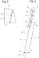
- a headrest of a vehicle seat as a whole is designated by the reference numeral 10 in the figures.
- Like reference numerals in the various figures indicate corresponding parts, even if small letters are readjusted or omitted.
- FIG Fig. 1 A perspective view of the headrest 10 is shown in FIG Fig. 1 shown.
- the headrest 10 includes a headrest 11 and a holding device 12, which in the present embodiment comprises two support rods 13a and 13b.
- the head unit 11 comprises a head rest plate 27 and a holder 18, which in the present Embodiment is a separate part, but alternatively may be integrally connected to the head rest plate 27.
- the support rods 13a and 13b are fixedly connected for stabilization with a rod 37 to a support bar bracket 38, which is part of the holding device 12.
- the head unit 11 has a head bearing surface 14, which forms an abutment for the head of the seat occupant.
- Lower ends 15a and 15b of the support rods 13a and 13b are e.g. on the structure backrest of a seat, not shown fastened.
- the head unit 11 is adjustable by means of an adjusting device 40 in different positions.
- the adjusting device 40 comprises a four-bar device 23 with two links 16 and 17.
- Each of the links 16 and 17 comprises arms 34a and 34b and a cross member 33 which connects the arms 34a and 34b.
- the traverse 33 is used in the embodiment essentially to improve the stability.
- the traverse 33 as connection of the arms 34a and 34b could alternatively be omitted.
- the link 16 forms with the support rod 13b a joint G1 (see Fig. 2 ) and the handlebar 17 forms with the support rod 13b a joint G2.
- the handlebar 16, in particular the arm 34b of the handlebar 16 also forms with the headrest 11, in the present case with a side portion 35 of the holder 18 of the headrest 11, a joint G3, while the handlebar 17, in particular the arm 34b of the handlebar 17, forms a joint G4 with the side portion 35 of the holder 18.
- handlebars 16 and 17 on a side region 35 opposite the side region 36 each have a hinge with the support rod 13 a and beyond a respective joint with the holder 18, which in Fig. 2 is not recognizable.
- the head assembly 11 is connected by means of a four-bar device 23 comprising the support bar bracket 38, the handlebars 16 and 17 and the head assembly 11 with the holder 18 relative to the holding device 12 between a rear position (see Figs Fig. 2 to 4 ) and a front position (see Fig. 5 ) in the directions x1 and x2 displaceable, wherein the head unit 11 thereby performs a curve movement with portions of a movement in the Z direction and portions of a movement in the X direction.
- the adjusting device 40 comprises a locking device 19, with which the headrest 11 can be locked in the rear position or the front position or in a position between the rear position and the front position.
- the locking device 19 comprises first locking means associated with the headset 11 and second locking means associated with the support bars 13a and 13b which can be releasably engaged.
- the supporting rods 13a and 13b are extended beyond the joints G1 and G2, in particular beyond the joints G3 and G4, in the direction z1 and are provided with the second locking means in the form of a locking area 20.
- the locking portion 20 is formed directly from the supporting rods 13a and 13b in the present embodiment.
- the first locking means are in the form of two bars 21a and 21b, which are movable relative to the holder 18 and are each provided with a tooth structure 22a and 22b, in this embodiment in the form of a dental splint. In Fig. 2 only the tooth structure 22b can be seen.
- Fig. 2 It can also be seen that the locking device 19 is in a locking position, that is, that the tooth structure 22b is engaged with the locking portion 20, so that the Head unit 11 is not movable between the rear and the front position.
- Fig. 3 is the articulated connection between the handlebar 17 and the support rod 13a to recognize in the form of a joint G5.
- a rear portion 24 of the holder 18 includes the tooth structures 22a and 22b which extend substantially in the x direction.
- a front portion 25 is provided with a guide device 26 for movably supporting the head rest plate 27 in directions z1 and z2 between an upper position and a lower position.
- the headrest plate 27 can be locked with a locking device in the upper position, the lower position and in intermediate positions between the upper position and the lower position.
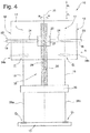
- Fig. 4 the head unit 11 is locked in the rear position by means of the locking device 23.
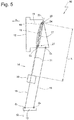
- Fig. 5 shows the headset 11 locked in the forward position.
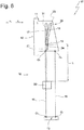
- Fig. 6 shows a sectional view, wherein the bars 21a and 21b are visible.
- the latch 21a and 21b are movably mounted.
- a spring 29a loads the latch 21a in the direction y2 in the locked position and a spring 29b loads the latch 21b in the direction y1 in the locked position.
- An actuator 30 is pivotally mounted about an axis a in the directions u1 and u2.
- the actuating element 30 can be fitted from the outside to the headrest 10 with a button 43 (only in FIG Fig. 2 designated) or alternatively or additionally electrically operated with a motor.
- the actuator 30 includes two arms 31 and 32. The arm 31 is in contact with the latch 21a and the arm 32 is in contact with the latch 21b.
- the latch 21a and 21b are in the locked position.
- the arm 31 displaces the latch 21a against the force of the spring 29a in the direction y1 and the arm 32 displaces the latch 21b against the force of the spring 29b in the direction y2 in the release position.
- the latch 21a is disengaged from the latch portion 20a, and the latch 21b is disengaged from the latch portion 20b.
- the headgear 11 can be moved between the rear position and the front position.
- the spring moves the latch 21a in the direction y2 and the spring 29b moves the latch 21b in the direction y1 to the latch position in engagement with the respective latch portion 20a and 20b, respectively.
- the actuating element 30 is moved back from the bars 21a and 21b in the direction u2 in the basic position.
- FIG. 6 Hook-shaped projections 39 a and 39 b are formed, which are formed on the front portion 25 of the holder 18. Grooves 41a and 41b are formed in the headrest plate 27.
- the projection 39a engages with the groove 41a
- the projection 39b engages with the groove 41b to movably guide the headrest plate 27 relative to the holder 18 in directions z1 and z2.
- the projections 39a and 39b and the grooves 41a and 41b are part of the guide device 26.
- a toothed rail 42 is visible as part of the locking device, with which a not shown, mounted on the holder 18 bolt can be releasably engaged to lock the head rest plate 27 in different height positions.
Landscapes
- Engineering & Computer Science (AREA)
- Aviation & Aerospace Engineering (AREA)
- Transportation (AREA)
- Mechanical Engineering (AREA)
- Transmission Devices (AREA)
- Seats For Vehicles (AREA)
- Chair Legs, Seat Parts, And Backrests (AREA)
Applications Claiming Priority (2)
| Application Number | Priority Date | Filing Date | Title |
|---|---|---|---|
| DE102018108520 | 2018-04-10 | ||
| DE102018109611.9A DE102018109611B4 (de) | 2018-04-10 | 2018-04-20 | Kopfstütze |
Publications (1)
| Publication Number | Publication Date |
|---|---|
| EP3552875A1 true EP3552875A1 (de) | 2019-10-16 |
Family
ID=65729051
Family Applications (1)
| Application Number | Title | Priority Date | Filing Date |
|---|---|---|---|
| EP19020111.1A Pending EP3552875A1 (de) | 2018-04-10 | 2019-03-08 | Kopfstütze |
Country Status (2)
| Country | Link |
|---|---|
| EP (1) | EP3552875A1 (zh) |
| CN (1) | CN110356302B (zh) |
Families Citing this family (2)
| Publication number | Priority date | Publication date | Assignee | Title |
|---|---|---|---|---|
| CN112977216A (zh) * | 2021-03-26 | 2021-06-18 | 重庆宏立至信科技发展集团有限公司 | 电动平移头枕 |
| CN113525205B (zh) * | 2021-08-26 | 2022-08-19 | 延锋国际座椅系统有限公司 | 一种座椅电动头枕 |
Citations (6)
| Publication number | Priority date | Publication date | Assignee | Title |
|---|---|---|---|---|
| JPS58121913A (ja) * | 1982-01-13 | 1983-07-20 | アイシン精機株式会社 | 車輌用座席のヘツドレスト装置 |
| DE10138248C1 (de) * | 2001-08-03 | 2002-12-05 | Autoliv Dev | Aktive Kopfstütze mit Verriegelungseinrichtung |
| KR20100130002A (ko) * | 2009-06-02 | 2010-12-10 | 주식회사 우보테크 | 헤드레스트 이동장치 |
| DE102010007942A1 (de) | 2010-02-12 | 2011-08-18 | Grammer AG, 92224 | Kopfstütze für Fahrzeugsitze |
| KR101694910B1 (ko) * | 2015-12-23 | 2017-01-10 | 주식회사 우보테크 | 헤드레스트 슬라이딩 장치 |
| DE102017007149A1 (de) | 2017-07-27 | 2019-01-31 | DILO Armaturen und Anlagenbau GmbH | Verfahren zur Lokalisierung von Leckstellen |
Family Cites Families (14)
| Publication number | Priority date | Publication date | Assignee | Title |
|---|---|---|---|---|
| US3102753A (en) * | 1960-08-04 | 1963-09-03 | Anton Lorenz | Multiple position reclining chair with extendible head-rest |
| JPH08266368A (ja) * | 1995-03-24 | 1996-10-15 | R Schmidt Gmbh | 自動車用頭部支持装置 |
| CN2259320Y (zh) * | 1996-07-09 | 1997-08-13 | 吕国清 | 可调整和置物的汽车椅背 |
| CN2590784Y (zh) * | 2002-12-31 | 2003-12-10 | 江苏省溧阳市汽车座椅调角器总厂 | 汽车座椅调节装置 |
| DE10325472A1 (de) * | 2003-06-05 | 2004-12-30 | Keiper Gmbh & Co. Kg | Crashaktive Kopfstütze |
| JP4640968B2 (ja) * | 2005-08-30 | 2011-03-02 | テイ・エス テック株式会社 | 車両用シートおよび車両用シートの組立方法 |
| FR2891506B1 (fr) * | 2005-10-05 | 2007-12-07 | Faurecia Sieges Automobile | Appui-tete pour siege de vehicule et siege comportant un tel appui-tete |
| CN2897039Y (zh) * | 2006-04-04 | 2007-05-09 | 孙立华 | 沙发枕头升降转动机构 |
| CN101243922B (zh) * | 2007-02-16 | 2011-05-11 | 湖北中航精机科技股份有限公司 | 一种座椅角度调节装置 |
| DE102013104760B3 (de) * | 2013-05-08 | 2014-07-31 | Faurecia Autositze Gmbh | Fahrzeugsitz, insbesondere für ein Kraftfahrzeug |
| US9315130B2 (en) * | 2013-11-11 | 2016-04-19 | Ford Global Technologies, Llc | Articulating head restraint |
| CN204415185U (zh) * | 2015-01-14 | 2015-06-24 | 新乡市新豪机电有限公司 | 座椅角度调节装置 |
| CN107444207B (zh) * | 2016-05-30 | 2019-11-22 | 比亚迪股份有限公司 | 汽车座椅头枕调节机构和汽车座椅 |
| CN106274579B (zh) * | 2016-08-29 | 2018-11-27 | 舟山岱美汽车零部件有限公司 | 座椅头枕的转动控制结构 |
-
2019
- 2019-03-08 EP EP19020111.1A patent/EP3552875A1/de active Pending
- 2019-04-09 CN CN201910278032.0A patent/CN110356302B/zh active Active
Patent Citations (6)
| Publication number | Priority date | Publication date | Assignee | Title |
|---|---|---|---|---|
| JPS58121913A (ja) * | 1982-01-13 | 1983-07-20 | アイシン精機株式会社 | 車輌用座席のヘツドレスト装置 |
| DE10138248C1 (de) * | 2001-08-03 | 2002-12-05 | Autoliv Dev | Aktive Kopfstütze mit Verriegelungseinrichtung |
| KR20100130002A (ko) * | 2009-06-02 | 2010-12-10 | 주식회사 우보테크 | 헤드레스트 이동장치 |
| DE102010007942A1 (de) | 2010-02-12 | 2011-08-18 | Grammer AG, 92224 | Kopfstütze für Fahrzeugsitze |
| KR101694910B1 (ko) * | 2015-12-23 | 2017-01-10 | 주식회사 우보테크 | 헤드레스트 슬라이딩 장치 |
| DE102017007149A1 (de) | 2017-07-27 | 2019-01-31 | DILO Armaturen und Anlagenbau GmbH | Verfahren zur Lokalisierung von Leckstellen |
Also Published As
| Publication number | Publication date |
|---|---|
| CN110356302B (zh) | 2022-05-27 |
| CN110356302A (zh) | 2019-10-22 |
Similar Documents
| Publication | Publication Date | Title |
|---|---|---|
| DE60300049T2 (de) | Kopfstütze für Kraftfahrzeugsitze | |
| DE102012112525B4 (de) | Nutzfahrzeugsitz mit doppelarretierbarem Querschlittenteil | |
| DE10348939B3 (de) | Kopfstütze für einen Fahrzeusitz | |
| DE102004005695B4 (de) | Fahrzeugsitz | |
| DE4309301C2 (de) | Fahrzeugsitz | |
| EP3543068B1 (de) | Kopfstütze | |
| DE102011108652B4 (de) | Fahrzeugsitz, insbesondere Kraftfahrzeugsitz | |
| DE102011078688B4 (de) | Tragkonstruktion für einen fahrzeugsitzrahmen | |
| EP2054260A1 (de) | Fahrzeugsitz, insbesondere nutzfahrzeugsitz | |
| DE102004050144B4 (de) | Aktive Kopfstütze mit entkoppeltem Lordoserahmen | |
| EP3552875A1 (de) | Kopfstütze | |
| DE102004061885B4 (de) | Sitzeinheitenstruktur für einen Kraftfahrzeugsitz | |
| DE102007027564A1 (de) | Fahrzeugsitz-Verstellvorrichtung | |
| DE3500496A1 (de) | Koerpergewichtseinstellvorrichtung einer sitzaufhaengung | |
| EP3360728A1 (de) | Kopfstütze | |
| DE102018109611B4 (de) | Kopfstütze | |
| DE10236259B4 (de) | Kopfstütze für Fahrzeugsitze | |
| DE102005005826B4 (de) | Kopfstütze | |
| DE10334551B3 (de) | Kopfstütze für die Rückenlehne von Automobilsitzen, insbesondere von Rücksitzen | |
| DE102008045021B3 (de) | Kopfstütze für Fahrzeuge | |
| DE2503695A1 (de) | Verschwenkbarer fahrersitz | |
| DE102012104812B4 (de) | Kraftfahrzeug mit einem feststehenden Überrollbügel | |
| DE102009036896B3 (de) | Kopfstütze für Fahrzeugsitze | |
| EP1332066B1 (de) | Gelenkhebelkonstruktion für ein sitzgestell | |
| DE10051344C1 (de) | Rückenlehne eines Kraftfahrzeugsitzes mit einer Kopfstütze |
Legal Events
| Date | Code | Title | Description |
|---|---|---|---|
| PUAI | Public reference made under article 153(3) epc to a published international application that has entered the european phase |
Free format text: ORIGINAL CODE: 0009012 |
|
| STAA | Information on the status of an ep patent application or granted ep patent |
Free format text: STATUS: THE APPLICATION HAS BEEN PUBLISHED |
|
| AK | Designated contracting states |
Kind code of ref document: A1 Designated state(s): AL AT BE BG CH CY CZ DE DK EE ES FI FR GB GR HR HU IE IS IT LI LT LU LV MC MK MT NL NO PL PT RO RS SE SI SK SM TR |
|
| AX | Request for extension of the european patent |
Extension state: BA ME |
|
| STAA | Information on the status of an ep patent application or granted ep patent |
Free format text: STATUS: REQUEST FOR EXAMINATION WAS MADE |
|
| 17P | Request for examination filed |
Effective date: 20191120 |
|
| RBV | Designated contracting states (corrected) |
Designated state(s): AL AT BE BG CH CY CZ DE DK EE ES FI FR GB GR HR HU IE IS IT LI LT LU LV MC MK MT NL NO PL PT RO RS SE SI SK SM TR |
|
| STAA | Information on the status of an ep patent application or granted ep patent |
Free format text: STATUS: EXAMINATION IS IN PROGRESS |
|
| STAA | Information on the status of an ep patent application or granted ep patent |
Free format text: STATUS: EXAMINATION IS IN PROGRESS |
|
| 17Q | First examination report despatched |
Effective date: 20201218 |
|
| RAP1 | Party data changed (applicant data changed or rights of an application transferred) |
Owner name: GRAMMER AG |