EP3552847B1 - Pneumatique - Google Patents
Pneumatique Download PDFInfo
- Publication number
- EP3552847B1 EP3552847B1 EP19168073.5A EP19168073A EP3552847B1 EP 3552847 B1 EP3552847 B1 EP 3552847B1 EP 19168073 A EP19168073 A EP 19168073A EP 3552847 B1 EP3552847 B1 EP 3552847B1
- Authority
- EP
- European Patent Office
- Prior art keywords
- groove
- tire
- tread
- main
- width
- Prior art date
- Legal status (The legal status is an assumption and is not a legal conclusion. Google has not performed a legal analysis and makes no representation as to the accuracy of the status listed.)
- Active
Links
Images


Classifications
-
- B—PERFORMING OPERATIONS; TRANSPORTING
- B60—VEHICLES IN GENERAL
- B60C—VEHICLE TYRES; TYRE INFLATION; TYRE CHANGING; CONNECTING VALVES TO INFLATABLE ELASTIC BODIES IN GENERAL; DEVICES OR ARRANGEMENTS RELATED TO TYRES
- B60C11/00—Tyre tread bands; Tread patterns; Anti-skid inserts
- B60C11/03—Tread patterns
- B60C11/13—Tread patterns characterised by the groove cross-section, e.g. for buttressing or preventing stone-trapping
- B60C11/1307—Tread patterns characterised by the groove cross-section, e.g. for buttressing or preventing stone-trapping with special features of the groove walls
- B60C11/1315—Tread patterns characterised by the groove cross-section, e.g. for buttressing or preventing stone-trapping with special features of the groove walls having variable inclination angles, e.g. warped groove walls
-
- B—PERFORMING OPERATIONS; TRANSPORTING
- B60—VEHICLES IN GENERAL
- B60C—VEHICLE TYRES; TYRE INFLATION; TYRE CHANGING; CONNECTING VALVES TO INFLATABLE ELASTIC BODIES IN GENERAL; DEVICES OR ARRANGEMENTS RELATED TO TYRES
- B60C11/00—Tyre tread bands; Tread patterns; Anti-skid inserts
- B60C11/03—Tread patterns
- B60C11/0306—Patterns comprising block rows or discontinuous ribs
- B60C11/0309—Patterns comprising block rows or discontinuous ribs further characterised by the groove cross-section
-
- B—PERFORMING OPERATIONS; TRANSPORTING
- B60—VEHICLES IN GENERAL
- B60C—VEHICLE TYRES; TYRE INFLATION; TYRE CHANGING; CONNECTING VALVES TO INFLATABLE ELASTIC BODIES IN GENERAL; DEVICES OR ARRANGEMENTS RELATED TO TYRES
- B60C11/00—Tyre tread bands; Tread patterns; Anti-skid inserts
- B60C11/03—Tread patterns
- B60C11/13—Tread patterns characterised by the groove cross-section, e.g. for buttressing or preventing stone-trapping
- B60C11/1376—Three dimensional block surfaces departing from the enveloping tread contour
- B60C11/1392—Three dimensional block surfaces departing from the enveloping tread contour with chamfered block edges
-
- B—PERFORMING OPERATIONS; TRANSPORTING
- B60—VEHICLES IN GENERAL
- B60C—VEHICLE TYRES; TYRE INFLATION; TYRE CHANGING; CONNECTING VALVES TO INFLATABLE ELASTIC BODIES IN GENERAL; DEVICES OR ARRANGEMENTS RELATED TO TYRES
- B60C11/00—Tyre tread bands; Tread patterns; Anti-skid inserts
- B60C11/03—Tread patterns
- B60C2011/0337—Tread patterns characterised by particular design features of the pattern
- B60C2011/0339—Grooves
- B60C2011/0341—Circumferential grooves
- B60C2011/0353—Circumferential grooves characterised by width
Definitions
- the present invention relates to a tire having, in a tread portion, a main groove that extends continuously in a tire circumferential direction.
- Japanese Laid-Open Patent Publication No. 5-338412 discloses a tire having, in a tread portion, main grooves that extend continuously in the tire circumferential direction.
- the main groove has a groove wall surface that extends so as to be tilted in a direction in which the groove width is reduced from a groove bottom surface toward a tread surface.
- the main groove exhibits good drainage performance also when the tread portion has been worn.
- a corner portion of a land portion between a tread surface of the tread portion and the groove wall surface of the main groove tends to have an acute angle.
- the corner portion is deformed when contacting with the ground, and thus receives little shearing force and eventually receives only low wear energy. Therefore, the corner portion of the land portion tends to cause abnormal wear in which wear concentrates on other portions.
- the corner portion has problems that stiffness of the tread portion is reduced, and, in particular, steering stability is poor when the tire is a new one.
- EP 1 116 604 A2 discloses a tire comprising a tread provided with three circumferentially extending fine grooves with enlarged groove bottom portions.
- JP 2002 211211 A discloses a tire comprising features according to a related technology.
- US 3 770 04 A also discloses a tire comprising features according to a related technology.
- JP S58 136502 A discloses a tire having a tread portion in which a main groove includes a first portion extending in a depth direction of the main groove and having a constant width and a second portion extending in the depth direction and having an arc shape with increasing and decreasing width.
- US 2 327 057 A discloses a tire comprising features according to a related technology.
- the present invention is made in view of the aforementioned circumstances, and a main object of the present invention is to provide a tire that can exhibit excellent wet performance over a long period of time while maintaining wear resistance and steering stability.
- the present invention is directed to a tire according to claim 1.
- the tread portion has at least one main groove that extends continuously in a tire circumferential direction.
- the main groove includes a first portion that extends in a depth direction of the main groove so as to have an almost constant groove width, and a second portion that has a groove width which increases from the first portion toward a groove bottom, on a transverse cross-section orthogonal to a length direction of the main groove.
- a depth from a tread surface of the tread portion to the boundary between the first portion and the second portion is 0.40 to 0.50 times a maximum depth of the main groove.
- One groove wall of the main groove and the other groove wall of the main groove are line-symmetric with respect to a center line of the main groove in a tire axial direction, on the transverse cross-section of the tire of the present invention.
- the main groove extends linearly along the tire circumferential direction.
- the first portion preferably extends from a groove edge of the main groove in the depth direction of the main groove.
- At least one of groove walls of the second portion is smoothly curved and recessed outward in a width direction of the main groove, on the transverse cross-section of the tire of the present invention.
- At least one of the groove walls of the second portion preferably includes a tilted portion that extends so as to be tilted in a direction in which a groove width of the main groove increases from a boundary between the first portion and the second portion, on the transverse cross-section of the tire of the present invention.
- An angle of the tilted portion relative to a normal line that passes through the groove edge of the main groove is preferably 10 to 70°.
- a difference between a groove width of the first portion and a maximum groove width of the second portion is preferably 3.0 to 6.0 mm.
- a groove bottom face of the main groove preferably extends linearly in the tire axial direction, on the transverse cross-section of the tire of the present invention.
- the main groove preferably extends in the tire circumferential direction so as to maintain a shape of the transverse cross-section.
- the main groove may zigzag in the tire circumferential direction.
- An angle of a groove wall of the first portion relative to the line normal to a tread is preferably 0 to 5° on the transverse cross-section of the tire of the present invention.
- An angle of each groove wall of the first portion relative to the line normal to the tread is preferably less than 1.0° on the transverse cross-section of the tire of the present invention.
- the tread portion of the tire according to the present invention has at least one main groove that extends continuously in the tire circumferential direction.
- the main groove includes the first portion that extends in the depth direction of the main groove so as to have an almost constant groove width, and the second portion that has a groove width which increases from the first portion toward a groove bottom, on the transverse cross-section orthogonal to the length direction of the main groove.
- the tire of the present invention can exhibit excellent wet performance over a long period of time due to the second portion having the groove width that increases toward the groove bottom.
- FIG. 1 is a transverse cross-sectional view of a tread portion 2 of a tire 1 according to the present embodiment.
- FIG. 1 shows a meridian cross-section that includes a tire rotation axis in a normal state of the tire 1.
- the tire 1 is preferably used as, for example, a pneumatic tire for passenger cars.
- the present invention is not limited to such an example.
- the tire 1 of the present invention may be used as, for example, a heavy duty tire.
- the "normal state” represents a state in which a tire is mounted to a normal rim and is inflated with air to a normal internal pressure, and no load is applied to the tire.
- dimensions of components of the tire and the like are represented by values measured in the normal state.
- the "normal rim” represents a rim that is defined by a standard, in a standard system including the standard with which the tire complies, for each tire, and is, for example, the "standard rim” in the JATMA standard, the "Design Rim” in the TRA standard, or the “Measuring Rim” in the ETRTO standard.
- the "normal internal pressure” represents an air pressure that is defined by a standard, in a standard system including the standard with which the tire complies, for each tire, and is the “maximum air pressure” in the JATMA standard, the maximum value recited in the table "TIRE LOAD LIMITS AT VARIOUS COLD INFLATION PRESSURES" in the TRA standard, or the “INFLATION PRESSURE” in the ETRTO standard.
- the tread portion 2 has four main grooves 3 that extend continuously in the tire circumferential direction.
- a groove width Wa of each main groove 3 is 3.0% to 6.0% of a tread width TW.
- the groove width Wa is a length between groove edges that appear on a tread surface of the tread portion 2.
- the tread width TW is a distance, in the tire axial direction, from one of tread ends Te to the other of the tread ends Te in the normal state.
- each main groove 3 preferably has a groove depth of, for example, 5 to 10 mm.
- the tread end Te is a ground contact position at the outermost side in the tire axial direction in a state where a normal load is applied to the tire 1 in the normal state and the tire 1 is brought into contact with a plane at a camber angle of 0°.
- the "normal load” represents a load that is defined by a standard, in a standard system including the standard with which the tire complies, for each tire, and is "maximum load capacity" in the JATMA standard, the maximum value recited in the table "TIRE LOAD LIMITS AT VARIOUS COLD INFLATION PRESSURES" in the TRA standard, or the "LOAD CAPACITY" in the ETRTO standard.
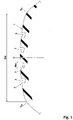
- FIG. 2 is an enlarged plan view of the main groove 3. As shown in FIG. 2 , the main groove 3 extends linearly along the tire circumferential direction. According to an alternative example not according to the invention, the main groove 3 may zigzag in the tire circumferential direction.
- FIG. 3 is a cross-sectional view of the main groove 3 as taken along a line A-A.
- the main groove 3 includes a first portion 6 which extends in the depth direction of the main groove 3 so as to have an almost constant groove width, and a second portion 7 that has a groove width that increases from the first portion 6 toward the groove bottom.
- the first portion 6 that extends so as to have an almost constant groove width includes a mode in which an angle between one of the groove walls of the first portion 6 and the other of the groove walls thereof is 0 to 5°.
- the angle is less than 1.0°.
- an angle of each groove wall of the first portion 6 relative to the line normal to the tread is 0 to 5° and more preferably less than 1.0°.
- the line normal to the tread is a line that passes through a groove edge of the main groove 3 and is orthogonal to the tread surface on the transverse cross-section of the tire.
- the tire 1 of the present invention as described above is a new tire in which the first portion 6 of the main groove 3 remains unworn, or is a tire in an initial stage of wear, a corner portion 8 of a land portion which is defined by the tread surface of the tread portion 2 and the groove wall of the main groove 3 is inhibited from having an acute angle. Therefore, while steering stability is maintained, abnormal wear in the tread portion 2 can be reduced.
- the tire of the present invention can exhibit excellent wet performance over a long period of time due to the second portion 7 having the groove width that increases toward the groove bottom.
- the first portion 6 preferably extends, for example, from a groove edge 3e of the main groove 3 in the depth direction of the main groove 3.
- the first portion 6 having such a structure can assuredly maintain steering stability obtained in the case of the tire being a new one. Furthermore, the first portion 6 having such a structure contributes to assuredly increasing of an area of the tread surface of the tread portion 2 so that grip force can be made high, as compared to a groove of which the groove width is gradually reduced from the groove edge. Furthermore, in the first portion 6, the groove width is unlikely to change even when ground contact pressure acts, and pumping sound at the time of ground contact can be reduced, as compared to a groove of which the groove width is gradually reduced from the groove edge.
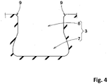
- the main groove 3 of the present invention may include, for example, a chamfered portion 9 formed from a tilted surface, between the first portion 6 and the tread surface of the tread portion 2, as in another embodiment shown in FIG. 4 .
- a depth d2 from the tread surface of the tread portion 2 to a boundary 10 between the first portion 6 and the second portion 7 is 0.40 to 0.50 times a maximum depth d1 of the main groove.
- the main groove 3 having such a structure allows well-balanced improvement of steering stability and wet performance.
- the main groove 3 having such a structure prevents a groove volume from being excessively great, and contributes to reduction of air column resonance sound.
- the second portion 7 for example, at least one of groove walls 7a is smoothly curved, and recessed outward in the width direction of the main groove 3. In the present embodiment, both the groove walls are smoothly curved and recessed. Furthermore, in the second portion 7, the groove width is gradually increased toward the groove bottom.
- the second portion 7 having such a structure facilitates removal of a main-groove-forming rib of a vulcanization mold from the tread portion 2 in vulcanization molding (hereinafter, this effect may be referred to as "improve demoldability").
- the first portion 6 has a constant groove width toward the depth direction of the main groove. Therefore, when the rib of the vulcanization mold is removed from the tread portion 2, damage near the boundary 10 can be reduced.
- the groove width is gradually reduced toward the groove bottom in a region on the outer side of the second portion 7 in the tire radial direction, the direction in which the groove wall tilts is changed at the boundary 10. Therefore, a portion near the boundary 10 may be easily damaged in vulcanization molding.
- At least one of the groove walls 7a of the second portion 7 includes a tilted portion 14 that extends so as to be tilted in a direction in which the groove width of the main groove 3 increases from the boundary 10 between the second portion 7 and the first portion 6.
- An angle ⁇ 1 of the tilted portion 14 relative to the normal line that passes through the groove edge 3e of the main groove 3 is preferably not less than 10°, more preferably not less than 20°, and even more preferably not less than 25°, and preferably not greater than 70°, more preferably not greater than 50°, and even more preferably not greater than 30°.
- the second portion 7 having such a structure exhibits the above-described effects while exhibiting excellent demoldability.
- An outermost side portion 12 of the second portion 7 is positioned, for example, outward of the groove edge 3e of the main groove 3.
- a maximum groove width W2 of the second portion 7 is preferably 1.15 to 1.25 times a groove width W1 of the first portion 6.
- the main groove 3 having such a structure exhibits excellent drainage performance while enhancing wear resistance.
- a difference between the groove width W1 of the first portion 6 and the maximum groove width W2 of the second portion 7 is preferably not less than 3.0 mm and more preferably not less than 4.0 mm, and preferably not greater than 6.0 mm and more preferably not greater than 5.0 mm.
- One groove wall 3a of the main groove 3 and the other groove wall 3b of the main groove 3 are line-symmetric with respect to the center line of the main groove 3 in the tire axial direction.
- the main groove 3 having such a structure allows the groove walls on both sides to be equally worn, and eventually allows wear resistance to be improved.
- a groove bottom face 13 of the main groove 3 preferably extends linearly in the tire axial direction.
- a portion, of the groove bottom face 13, near the center in the tire axial direction is unlikely to be bent, and the groove volume of the main groove 3 is unlikely to be reduced even in a state where stress in the tire axial direction acts on the tread portion 2. Therefore, cornering performance at a wet road surface is improved.
- the outermost side portion 12 of the second portion 7 preferably extends parallel to the groove edge 3e of the main groove 3.
- the entirety of the main groove 3 preferably extends in the tire circumferential direction so as to maintain the transverse cross-sectional shape described above.
- the main groove 3 having such a structure even when wear of the tread portion 2 is developed, the groove edge 3e that appears on the outer surface thereof maintains the linear shape so that uneven wear near the groove edge 3e can be reduced.
- the main groove 3 may be formed, for example, so as to increase or reduce the groove width of the second portion 7 in the tire circumferential direction.
- Pneumatic tires each having the above-described main groove and having the size of 185/65R15 were produced as sample tires based on the specifications indicated in Table 1.
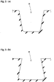
- a tire that had a main groove having a cross-sectional shape shown in FIG. 5 (a) was produced as the sample tire.
- the groove width of the main groove a was gradually reduced from the groove edge of the main groove toward the groove bottom.
- a tire that had a main groove having a cross-sectional shape shown in FIG. 5 (b) was produced as the sample tire.
- the groove width of the main groove a was gradually increased from the groove edge of the main groove toward the groove bottom.
- the groove volume of the main groove is equal to the groove volume of the main groove of example 1.
- test tire was tested for steering stability, wet performance after wear, and presence or absence of abnormal wear. Specifications common to all the test tires and the test method are as follows.
Landscapes
- Engineering & Computer Science (AREA)
- Mechanical Engineering (AREA)
- Tires In General (AREA)
Claims (9)
- Pneumatique (1) comprenantune portion formant bande de roulement (2), dans lequella portion formant bande de roulement a quatre rainures principales (3) s'étendant en continu linéairement le long d'une direction circonférentielle du pneumatique,chaque rainure principale (3) inclut une première portion (6) qui s'étend dans une direction de la profondeur de la rainure principale (3) de manière à avoir largeur de rainure pratiquement constante, et une seconde portion (7) qui a une largeur de rainure qui augmente depuis la première portion (6) vers un fond de rainure, sur une section transversale orthogonale à une direction longitudinale de la rainure principale (3), etune paroi de rainure (3a) de la rainure principale (3) et l'autre paroi de rainure (3b) de la rainure principale (3) sont en symétrie d'axe par rapport à une ligne centrale de la rainure principale (3) dans une direction axiale du pneumatique, sur la section transversale,dans lequelune largeur de rainure (Wa) de chaque rainure principale (3), qui est une longueur entre des bords de rainure qui apparaissent sur une surface de bande de roulement de la portion formant bande de roulement (2), est de 3,0 % à 6,0 % d'une largeur de bande de roulement (TW), la largeur de bande de roulement (TW) étant une distance, dans la direction axiale du pneumatique, depuis l'une des extrémités de bande de roulement (Te) jusqu'à l'autre des extrémités de bande de roulement (Te) dans l'état normal, dans lequel une extrémité de bande de roulement (Te) est une position de contact au sol au niveau du côté le plus extérieur dans la direction axiale du pneumatique dans un état où une charge normale est appliquée sur le pneumatique (1) dans l'état normal et le pneumatique (1) est amené en contact avec un plan à un angle de cambrure de 0°, l'état normal étant un état dans lequel le pneumatique (1) est monté sur une jante normale et est gonflé avec de l'air à une pression interne normale, et aucune charge n'étant appliquée sur le pneumatique (1), etune profondeur (d2) depuis une surface de bande de roulement de la portion formant bande de roulement (2) jusqu'à la frontière (10) entre la première portion (6) et la seconde portion (7) est 0,40 à 0,50 fois une profondeur maximum (d1) des rainures principales (3).
- Bandage pneumatique (1) selon la revendication 1, dans lequel la première portion (6) s'étend depuis un bord de rainure (3e) des rainures principales (3) dans la direction de la profondeur des rainures principales (3).
- Pneumatique (1) selon la revendication 1 ou 2, dans lequel l'une au moins des parois de rainure (7a) de la seconde portion (7) est incurvée en douceur et évidée vers l'extérieur dans une direction de la largeur des rainures principales (3), sur la section transversale.
- Pneumatique (1) selon l'une quelconque des revendications 1 à 3, dans lequell'une au moins des parois de rainure (7a) de la seconde portion (7) inclut une portion inclinée (14) qui s'étend de manière à être inclinée dans une direction dans laquelle une largeur de rainure des rainures principales (3) augmente depuis une frontière (10) entre la première portion (6) et la seconde portion (7), sur la section transversale, etun angle de la portion inclinée (14) relativement à une ligne normale qui passe à travers le bord de rainure (3e) des rainures principales (3) est de 10 à 70°.
- Pneumatique (1) selon l'une quelconque des revendications 1 à 4, dans lequel une différence entre une largeur de rainure (W1) de la première portion (6) et une largeur de rainure maximum (W2) de la seconde portion (7) est de 3,0 à 6,0 mm.
- Pneumatique (1) selon l'une quelconque des revendications 1 à 5, dans lequel une face de fond de rainure (13) des rainures principales (3) s'étend linéairement dans la direction axiale du pneumatique, sur la section transversale.
- Pneumatique (1) selon l'une quelconque des revendications 1 à 6, dans lequel les rainures principales (3) s'étendent dans la direction circonférentielle du pneumatique de manière à maintenir une forme de la section transversale.
- Pneumatique (1) selon l'une quelconque des revendications 1 à 7, dans lequel un angle d'une paroi de rainure de la première portion (6) relativement à la ligne normale par rapport à une bande de roulement est de 0 à 5° sur la section transversale.
- Pneumatique (1) selon l'une quelconque des revendications 1 à 8, dans lequel un angle de chaque paroi de rainure de la première portion (6) relativement à la ligne normale par rapport à la bande de roulement est inférieur à 1,0° sur la section transversale.
Applications Claiming Priority (1)
| Application Number | Priority Date | Filing Date | Title |
|---|---|---|---|
| JP2018076338A JP7172106B2 (ja) | 2018-04-11 | 2018-04-11 | タイヤ |
Publications (2)
| Publication Number | Publication Date |
|---|---|
| EP3552847A1 EP3552847A1 (fr) | 2019-10-16 |
| EP3552847B1 true EP3552847B1 (fr) | 2022-09-07 |
Family
ID=66102932
Family Applications (1)
| Application Number | Title | Priority Date | Filing Date |
|---|---|---|---|
| EP19168073.5A Active EP3552847B1 (fr) | 2018-04-11 | 2019-04-09 | Pneumatique |
Country Status (2)
| Country | Link |
|---|---|
| EP (1) | EP3552847B1 (fr) |
| JP (1) | JP7172106B2 (fr) |
Families Citing this family (4)
| Publication number | Priority date | Publication date | Assignee | Title |
|---|---|---|---|---|
| JP7539310B2 (ja) * | 2020-12-16 | 2024-08-23 | 株式会社ブリヂストン | 乗用車用空気入りラジアルタイヤ |
| JP2022095315A (ja) * | 2020-12-16 | 2022-06-28 | 株式会社ブリヂストン | 乗用車用空気入りラジアルタイヤ |
| JP7701207B2 (ja) * | 2021-08-04 | 2025-07-01 | 株式会社ブリヂストン | タイヤ |
| JP2023178048A (ja) * | 2022-06-03 | 2023-12-14 | 住友ゴム工業株式会社 | タイヤ |
Family Cites Families (13)
| Publication number | Priority date | Publication date | Assignee | Title |
|---|---|---|---|---|
| US2327057A (en) * | 1939-08-23 | 1943-08-17 | Goodrich Co B F | Tire tread |
| FR1163341A (fr) * | 1956-12-18 | 1958-09-24 | Mft Fr Pneumatiques Michelin | Perfectionnements aux bandes de roulement des pneumatiques pour véhicules |
| US3770040A (en) * | 1971-09-15 | 1973-11-06 | De Cicco M Augusta | Tire with safety indicator means |
| JPS58136502A (ja) * | 1982-02-08 | 1983-08-13 | Sumitomo Rubber Ind Ltd | タイヤトレツド |
| JP3096357B2 (ja) | 1992-06-04 | 2000-10-10 | 住友ゴム工業株式会社 | 重荷重用空気入りタイヤ |
| JP3101555B2 (ja) * | 1995-11-28 | 2000-10-23 | 住友ゴム工業株式会社 | 空気入りタイヤ |
| JP3450953B2 (ja) * | 1995-12-18 | 2003-09-29 | 住友ゴム工業株式会社 | 乗用車用タイヤ |
| US6412531B1 (en) | 1999-07-15 | 2002-07-02 | Michelin Recherche Et Technique S.A. | Tire tread having groove walls with compound contours |
| JP4615655B2 (ja) * | 2000-01-17 | 2011-01-19 | 株式会社ブリヂストン | 空気入りタイヤ |
| JP2002211211A (ja) | 2001-01-12 | 2002-07-31 | Bridgestone Corp | 空気入りラジアルタイヤ |
| JP4955022B2 (ja) | 2009-01-06 | 2012-06-20 | 東洋ゴム工業株式会社 | 空気入りタイヤ |
| DE102015205006A1 (de) | 2015-03-19 | 2016-09-22 | Continental Reifen Deutschland Gmbh | Fahrzeugluftreifen |
| DE102015215455A1 (de) | 2015-08-13 | 2017-02-16 | Continental Reifen Deutschland Gmbh | Fahrzeugluftreifen |
-
2018
- 2018-04-11 JP JP2018076338A patent/JP7172106B2/ja active Active
-
2019
- 2019-04-09 EP EP19168073.5A patent/EP3552847B1/fr active Active
Also Published As
| Publication number | Publication date |
|---|---|
| EP3552847A1 (fr) | 2019-10-16 |
| JP7172106B2 (ja) | 2022-11-16 |
| JP2019182246A (ja) | 2019-10-24 |
Similar Documents
| Publication | Publication Date | Title |
|---|---|---|
| EP3178668B1 (fr) | Pneumatique | |
| CN106985618B (zh) | 轮胎 | |
| EP3552847B1 (fr) | Pneumatique | |
| KR102569782B1 (ko) | 타이어 | |
| JP7310434B2 (ja) | タイヤ | |
| CN114103558B (zh) | 轮胎 | |
| JP2020196286A (ja) | タイヤ | |
| EP3689642B1 (fr) | Pneumatique | |
| US20200262248A1 (en) | Pneumatic tyre, tyre mold and method for manufacturing pneumatic tyre using the same | |
| EP3354484B1 (fr) | Pneumatique | |
| CN112009177B (zh) | 轮胎 | |
| CN110091676B (zh) | 轮胎 | |
| JP7669775B2 (ja) | タイヤ | |
| EP4245571B1 (fr) | Pneumatique | |
| EP3925797B1 (fr) | Pneumatique | |
| CN112046205A (zh) | 轮胎 | |
| EP3970996B1 (fr) | Pneumatique | |
| US20220339965A1 (en) | Tire | |
| US11691459B2 (en) | Tire | |
| JP7669781B2 (ja) | タイヤ | |
| JP7625855B2 (ja) | タイヤ | |
| EP4245572B1 (fr) | Pneumatique | |
| JP7707719B2 (ja) | 空気入りタイヤ | |
| JP7683290B2 (ja) | タイヤ | |
| JP7643039B2 (ja) | タイヤ |
Legal Events
| Date | Code | Title | Description |
|---|---|---|---|
| PUAI | Public reference made under article 153(3) epc to a published international application that has entered the european phase |
Free format text: ORIGINAL CODE: 0009012 |
|
| STAA | Information on the status of an ep patent application or granted ep patent |
Free format text: STATUS: THE APPLICATION HAS BEEN PUBLISHED |
|
| AK | Designated contracting states |
Kind code of ref document: A1 Designated state(s): AL AT BE BG CH CY CZ DE DK EE ES FI FR GB GR HR HU IE IS IT LI LT LU LV MC MK MT NL NO PL PT RO RS SE SI SK SM TR |
|
| AX | Request for extension of the european patent |
Extension state: BA ME |
|
| STAA | Information on the status of an ep patent application or granted ep patent |
Free format text: STATUS: REQUEST FOR EXAMINATION WAS MADE |
|
| 17P | Request for examination filed |
Effective date: 20200317 |
|
| RBV | Designated contracting states (corrected) |
Designated state(s): AL AT BE BG CH CY CZ DE DK EE ES FI FR GB GR HR HU IE IS IT LI LT LU LV MC MK MT NL NO PL PT RO RS SE SI SK SM TR |
|
| STAA | Information on the status of an ep patent application or granted ep patent |
Free format text: STATUS: EXAMINATION IS IN PROGRESS |
|
| 17Q | First examination report despatched |
Effective date: 20200428 |
|
| GRAP | Despatch of communication of intention to grant a patent |
Free format text: ORIGINAL CODE: EPIDOSNIGR1 |
|
| STAA | Information on the status of an ep patent application or granted ep patent |
Free format text: STATUS: GRANT OF PATENT IS INTENDED |
|
| INTG | Intention to grant announced |
Effective date: 20220523 |
|
| RIN1 | Information on inventor provided before grant (corrected) |
Inventor name: NAKAJIMA, KOICHI |
|
| GRAS | Grant fee paid |
Free format text: ORIGINAL CODE: EPIDOSNIGR3 |
|
| GRAA | (expected) grant |
Free format text: ORIGINAL CODE: 0009210 |
|
| STAA | Information on the status of an ep patent application or granted ep patent |
Free format text: STATUS: THE PATENT HAS BEEN GRANTED |
|
| AK | Designated contracting states |
Kind code of ref document: B1 Designated state(s): AL AT BE BG CH CY CZ DE DK EE ES FI FR GB GR HR HU IE IS IT LI LT LU LV MC MK MT NL NO PL PT RO RS SE SI SK SM TR |
|
| REG | Reference to a national code |
Ref country code: GB Ref legal event code: FG4D |
|
| REG | Reference to a national code |
Ref country code: CH Ref legal event code: EP Ref country code: AT Ref legal event code: REF Ref document number: 1516731 Country of ref document: AT Kind code of ref document: T Effective date: 20220915 |
|
| REG | Reference to a national code |
Ref country code: IE Ref legal event code: FG4D |
|
| REG | Reference to a national code |
Ref country code: DE Ref legal event code: R096 Ref document number: 602019019146 Country of ref document: DE |
|
| REG | Reference to a national code |
Ref country code: LT Ref legal event code: MG9D |
|
| REG | Reference to a national code |
Ref country code: NL Ref legal event code: MP Effective date: 20220907 |
|
| PG25 | Lapsed in a contracting state [announced via postgrant information from national office to epo] |
Ref country code: SE Free format text: LAPSE BECAUSE OF FAILURE TO SUBMIT A TRANSLATION OF THE DESCRIPTION OR TO PAY THE FEE WITHIN THE PRESCRIBED TIME-LIMIT Effective date: 20220907 Ref country code: RS Free format text: LAPSE BECAUSE OF FAILURE TO SUBMIT A TRANSLATION OF THE DESCRIPTION OR TO PAY THE FEE WITHIN THE PRESCRIBED TIME-LIMIT Effective date: 20220907 Ref country code: NO Free format text: LAPSE BECAUSE OF FAILURE TO SUBMIT A TRANSLATION OF THE DESCRIPTION OR TO PAY THE FEE WITHIN THE PRESCRIBED TIME-LIMIT Effective date: 20221207 Ref country code: LV Free format text: LAPSE BECAUSE OF FAILURE TO SUBMIT A TRANSLATION OF THE DESCRIPTION OR TO PAY THE FEE WITHIN THE PRESCRIBED TIME-LIMIT Effective date: 20220907 Ref country code: LT Free format text: LAPSE BECAUSE OF FAILURE TO SUBMIT A TRANSLATION OF THE DESCRIPTION OR TO PAY THE FEE WITHIN THE PRESCRIBED TIME-LIMIT Effective date: 20220907 Ref country code: FI Free format text: LAPSE BECAUSE OF FAILURE TO SUBMIT A TRANSLATION OF THE DESCRIPTION OR TO PAY THE FEE WITHIN THE PRESCRIBED TIME-LIMIT Effective date: 20220907 |
|
| REG | Reference to a national code |
Ref country code: AT Ref legal event code: MK05 Ref document number: 1516731 Country of ref document: AT Kind code of ref document: T Effective date: 20220907 |
|
| PG25 | Lapsed in a contracting state [announced via postgrant information from national office to epo] |
Ref country code: HR Free format text: LAPSE BECAUSE OF FAILURE TO SUBMIT A TRANSLATION OF THE DESCRIPTION OR TO PAY THE FEE WITHIN THE PRESCRIBED TIME-LIMIT Effective date: 20220907 Ref country code: GR Free format text: LAPSE BECAUSE OF FAILURE TO SUBMIT A TRANSLATION OF THE DESCRIPTION OR TO PAY THE FEE WITHIN THE PRESCRIBED TIME-LIMIT Effective date: 20221208 |
|
| PG25 | Lapsed in a contracting state [announced via postgrant information from national office to epo] |
Ref country code: SM Free format text: LAPSE BECAUSE OF FAILURE TO SUBMIT A TRANSLATION OF THE DESCRIPTION OR TO PAY THE FEE WITHIN THE PRESCRIBED TIME-LIMIT Effective date: 20220907 Ref country code: RO Free format text: LAPSE BECAUSE OF FAILURE TO SUBMIT A TRANSLATION OF THE DESCRIPTION OR TO PAY THE FEE WITHIN THE PRESCRIBED TIME-LIMIT Effective date: 20220907 Ref country code: PT Free format text: LAPSE BECAUSE OF FAILURE TO SUBMIT A TRANSLATION OF THE DESCRIPTION OR TO PAY THE FEE WITHIN THE PRESCRIBED TIME-LIMIT Effective date: 20230109 Ref country code: ES Free format text: LAPSE BECAUSE OF FAILURE TO SUBMIT A TRANSLATION OF THE DESCRIPTION OR TO PAY THE FEE WITHIN THE PRESCRIBED TIME-LIMIT Effective date: 20220907 Ref country code: CZ Free format text: LAPSE BECAUSE OF FAILURE TO SUBMIT A TRANSLATION OF THE DESCRIPTION OR TO PAY THE FEE WITHIN THE PRESCRIBED TIME-LIMIT Effective date: 20220907 Ref country code: AT Free format text: LAPSE BECAUSE OF FAILURE TO SUBMIT A TRANSLATION OF THE DESCRIPTION OR TO PAY THE FEE WITHIN THE PRESCRIBED TIME-LIMIT Effective date: 20220907 |
|
| PG25 | Lapsed in a contracting state [announced via postgrant information from national office to epo] |
Ref country code: SK Free format text: LAPSE BECAUSE OF FAILURE TO SUBMIT A TRANSLATION OF THE DESCRIPTION OR TO PAY THE FEE WITHIN THE PRESCRIBED TIME-LIMIT Effective date: 20220907 Ref country code: PL Free format text: LAPSE BECAUSE OF FAILURE TO SUBMIT A TRANSLATION OF THE DESCRIPTION OR TO PAY THE FEE WITHIN THE PRESCRIBED TIME-LIMIT Effective date: 20220907 Ref country code: IS Free format text: LAPSE BECAUSE OF FAILURE TO SUBMIT A TRANSLATION OF THE DESCRIPTION OR TO PAY THE FEE WITHIN THE PRESCRIBED TIME-LIMIT Effective date: 20230107 Ref country code: EE Free format text: LAPSE BECAUSE OF FAILURE TO SUBMIT A TRANSLATION OF THE DESCRIPTION OR TO PAY THE FEE WITHIN THE PRESCRIBED TIME-LIMIT Effective date: 20220907 |
|
| REG | Reference to a national code |
Ref country code: DE Ref legal event code: R097 Ref document number: 602019019146 Country of ref document: DE |
|
| P01 | Opt-out of the competence of the unified patent court (upc) registered |
Effective date: 20230510 |
|
| PG25 | Lapsed in a contracting state [announced via postgrant information from national office to epo] |
Ref country code: NL Free format text: LAPSE BECAUSE OF FAILURE TO SUBMIT A TRANSLATION OF THE DESCRIPTION OR TO PAY THE FEE WITHIN THE PRESCRIBED TIME-LIMIT Effective date: 20220907 Ref country code: AL Free format text: LAPSE BECAUSE OF FAILURE TO SUBMIT A TRANSLATION OF THE DESCRIPTION OR TO PAY THE FEE WITHIN THE PRESCRIBED TIME-LIMIT Effective date: 20220907 |
|
| PLBE | No opposition filed within time limit |
Free format text: ORIGINAL CODE: 0009261 |
|
| STAA | Information on the status of an ep patent application or granted ep patent |
Free format text: STATUS: NO OPPOSITION FILED WITHIN TIME LIMIT |
|
| PG25 | Lapsed in a contracting state [announced via postgrant information from national office to epo] |
Ref country code: DK Free format text: LAPSE BECAUSE OF FAILURE TO SUBMIT A TRANSLATION OF THE DESCRIPTION OR TO PAY THE FEE WITHIN THE PRESCRIBED TIME-LIMIT Effective date: 20220907 |
|
| 26N | No opposition filed |
Effective date: 20230608 |
|
| PG25 | Lapsed in a contracting state [announced via postgrant information from national office to epo] |
Ref country code: SI Free format text: LAPSE BECAUSE OF FAILURE TO SUBMIT A TRANSLATION OF THE DESCRIPTION OR TO PAY THE FEE WITHIN THE PRESCRIBED TIME-LIMIT Effective date: 20220907 |
|
| REG | Reference to a national code |
Ref country code: CH Ref legal event code: PL |
|
| GBPC | Gb: european patent ceased through non-payment of renewal fee |
Effective date: 20230409 |
|
| PG25 | Lapsed in a contracting state [announced via postgrant information from national office to epo] |
Ref country code: LU Free format text: LAPSE BECAUSE OF NON-PAYMENT OF DUE FEES Effective date: 20230409 |
|
| REG | Reference to a national code |
Ref country code: BE Ref legal event code: MM Effective date: 20230430 |
|
| PG25 | Lapsed in a contracting state [announced via postgrant information from national office to epo] |
Ref country code: MC Free format text: LAPSE BECAUSE OF FAILURE TO SUBMIT A TRANSLATION OF THE DESCRIPTION OR TO PAY THE FEE WITHIN THE PRESCRIBED TIME-LIMIT Effective date: 20220907 |
|
| PG25 | Lapsed in a contracting state [announced via postgrant information from national office to epo] |
Ref country code: GB Free format text: LAPSE BECAUSE OF NON-PAYMENT OF DUE FEES Effective date: 20230409 |
|
| PG25 | Lapsed in a contracting state [announced via postgrant information from national office to epo] |
Ref country code: MC Free format text: LAPSE BECAUSE OF FAILURE TO SUBMIT A TRANSLATION OF THE DESCRIPTION OR TO PAY THE FEE WITHIN THE PRESCRIBED TIME-LIMIT Effective date: 20220907 Ref country code: LI Free format text: LAPSE BECAUSE OF NON-PAYMENT OF DUE FEES Effective date: 20230430 Ref country code: GB Free format text: LAPSE BECAUSE OF NON-PAYMENT OF DUE FEES Effective date: 20230409 Ref country code: CH Free format text: LAPSE BECAUSE OF NON-PAYMENT OF DUE FEES Effective date: 20230430 |
|
| REG | Reference to a national code |
Ref country code: IE Ref legal event code: MM4A |
|
| PG25 | Lapsed in a contracting state [announced via postgrant information from national office to epo] |
Ref country code: BE Free format text: LAPSE BECAUSE OF NON-PAYMENT OF DUE FEES Effective date: 20230430 |
|
| PG25 | Lapsed in a contracting state [announced via postgrant information from national office to epo] |
Ref country code: IE Free format text: LAPSE BECAUSE OF NON-PAYMENT OF DUE FEES Effective date: 20230409 |
|
| PG25 | Lapsed in a contracting state [announced via postgrant information from national office to epo] |
Ref country code: IE Free format text: LAPSE BECAUSE OF NON-PAYMENT OF DUE FEES Effective date: 20230409 |
|
| PG25 | Lapsed in a contracting state [announced via postgrant information from national office to epo] |
Ref country code: IT Free format text: LAPSE BECAUSE OF FAILURE TO SUBMIT A TRANSLATION OF THE DESCRIPTION OR TO PAY THE FEE WITHIN THE PRESCRIBED TIME-LIMIT Effective date: 20220907 |
|
| PG25 | Lapsed in a contracting state [announced via postgrant information from national office to epo] |
Ref country code: BG Free format text: LAPSE BECAUSE OF FAILURE TO SUBMIT A TRANSLATION OF THE DESCRIPTION OR TO PAY THE FEE WITHIN THE PRESCRIBED TIME-LIMIT Effective date: 20220907 |
|
| PG25 | Lapsed in a contracting state [announced via postgrant information from national office to epo] |
Ref country code: BG Free format text: LAPSE BECAUSE OF FAILURE TO SUBMIT A TRANSLATION OF THE DESCRIPTION OR TO PAY THE FEE WITHIN THE PRESCRIBED TIME-LIMIT Effective date: 20220907 |
|
| PGFP | Annual fee paid to national office [announced via postgrant information from national office to epo] |
Ref country code: DE Payment date: 20250305 Year of fee payment: 7 |
|
| PG25 | Lapsed in a contracting state [announced via postgrant information from national office to epo] |
Ref country code: CY Free format text: LAPSE BECAUSE OF FAILURE TO SUBMIT A TRANSLATION OF THE DESCRIPTION OR TO PAY THE FEE WITHIN THE PRESCRIBED TIME-LIMIT; INVALID AB INITIO Effective date: 20190409 |
|
| PG25 | Lapsed in a contracting state [announced via postgrant information from national office to epo] |
Ref country code: HU Free format text: LAPSE BECAUSE OF FAILURE TO SUBMIT A TRANSLATION OF THE DESCRIPTION OR TO PAY THE FEE WITHIN THE PRESCRIBED TIME-LIMIT; INVALID AB INITIO Effective date: 20190409 |
|
| PG25 | Lapsed in a contracting state [announced via postgrant information from national office to epo] |
Ref country code: TR Free format text: LAPSE BECAUSE OF FAILURE TO SUBMIT A TRANSLATION OF THE DESCRIPTION OR TO PAY THE FEE WITHIN THE PRESCRIBED TIME-LIMIT Effective date: 20220907 |
|
| PGFP | Annual fee paid to national office [announced via postgrant information from national office to epo] |
Ref country code: FR Payment date: 20260309 Year of fee payment: 8 |