EP3552749A1 - Spulendrahtausgabesystem - Google Patents
Spulendrahtausgabesystem Download PDFInfo
- Publication number
- EP3552749A1 EP3552749A1 EP19151915.6A EP19151915A EP3552749A1 EP 3552749 A1 EP3552749 A1 EP 3552749A1 EP 19151915 A EP19151915 A EP 19151915A EP 3552749 A1 EP3552749 A1 EP 3552749A1
- Authority
- EP
- European Patent Office
- Prior art keywords
- wire
- welding wire
- coil
- staged
- wire transfer
- Prior art date
- Legal status (The legal status is an assumption and is not a legal conclusion. Google has not performed a legal analysis and makes no representation as to the accuracy of the status listed.)
- Granted
Links
Images


Classifications
-
- B—PERFORMING OPERATIONS; TRANSPORTING
- B65—CONVEYING; PACKING; STORING; HANDLING THIN OR FILAMENTARY MATERIAL
- B65H—HANDLING THIN OR FILAMENTARY MATERIAL, e.g. SHEETS, WEBS, CABLES
- B65H49/00—Unwinding or paying-out filamentary material; Supporting, storing or transporting packages from which filamentary material is to be withdrawn or paid-out
- B65H49/02—Methods or apparatus in which packages do not rotate
- B65H49/04—Package-supporting devices
- B65H49/06—Package-supporting devices for a single operative package
- B65H49/08—Package-supporting devices for a single operative package enclosing the package
-
- B—PERFORMING OPERATIONS; TRANSPORTING
- B23—MACHINE TOOLS; METAL-WORKING NOT OTHERWISE PROVIDED FOR
- B23K—SOLDERING OR UNSOLDERING; WELDING; CLADDING OR PLATING BY SOLDERING OR WELDING; CUTTING BY APPLYING HEAT LOCALLY, e.g. FLAME CUTTING; WORKING BY LASER BEAM
- B23K9/00—Arc welding or cutting
- B23K9/12—Automatic feeding or moving of electrodes or work for spot or seam welding or cutting
- B23K9/133—Means for feeding electrodes, e.g. drums, rolls, motors
- B23K9/1333—Dereeling means
-
- B—PERFORMING OPERATIONS; TRANSPORTING
- B65—CONVEYING; PACKING; STORING; HANDLING THIN OR FILAMENTARY MATERIAL
- B65H—HANDLING THIN OR FILAMENTARY MATERIAL, e.g. SHEETS, WEBS, CABLES
- B65H49/00—Unwinding or paying-out filamentary material; Supporting, storing or transporting packages from which filamentary material is to be withdrawn or paid-out
- B65H49/02—Methods or apparatus in which packages do not rotate
- B65H49/04—Package-supporting devices
- B65H49/10—Package-supporting devices for one operative package and one or more reserve packages
- B65H49/12—Package-supporting devices for one operative package and one or more reserve packages the reserve packages being mounted to permit manual or automatic transfer to operating position
-
- B—PERFORMING OPERATIONS; TRANSPORTING
- B65—CONVEYING; PACKING; STORING; HANDLING THIN OR FILAMENTARY MATERIAL
- B65H—HANDLING THIN OR FILAMENTARY MATERIAL, e.g. SHEETS, WEBS, CABLES
- B65H57/00—Guides for filamentary materials; Supports therefor
- B65H57/18—Guides for filamentary materials; Supports therefor mounted to facilitate unwinding of material from packages
-
- B—PERFORMING OPERATIONS; TRANSPORTING
- B65—CONVEYING; PACKING; STORING; HANDLING THIN OR FILAMENTARY MATERIAL
- B65H—HANDLING THIN OR FILAMENTARY MATERIAL, e.g. SHEETS, WEBS, CABLES
- B65H2701/00—Handled material; Storage means
- B65H2701/30—Handled filamentary material
- B65H2701/36—Wires
Definitions
- the invention described herein pertains generally to a method and apparatus for Improving existing bulk wire transfer methodologies and more particularly, to welding wire packages for use as an endless wire container such that the welding wire of multiple containers can be linked together to produce an uninterrupted flow of welding wire to a welding operation.
- Welding wire used in high production operations, such as robotic welding stations, is provided in large packages having over 200 pounds of wire.
- the welding wire In these packages Is looped into convolutions of wire loops forming a wire coil extending around a central core or a central clearance bore.
- a welding wire transfer system for use with at least a pair of endless welding wire containers, at least one of said containers is an in-process supply container containing a coil of wire and at least one other of said containers is a staged supply container containing a coil of wire with a start end of said staged container welding wire butt-welded to a tail of said in-process container welding wire, which Includes: a vertical shaft; and a horizontal shaft extending normal to the vertical shaft and containing a welding wire transfer guide, the guide having an outwardly-facing curvilinear groove, one end of the groove of the welding wire transfer guide positioned nearly tangent to an outer diameter of the in-process coll of wire and an opposed end of the groove positioned nearly tangent to an inner diameter of the staged coil of welding wire.
- the welding wire transfer system further includes: a magnetically positionable wire transfer arm, the vertical shaft having a pivotable collar and at least one magnet and a fixed collar having at least two magnets in a spaced apart relationship.
- the fixed collar will have at least four magnets in a spaced apart relationship.
- Each welding wire container may be fitted with an optional dome having at least two slots in at least one side in a geometric relationship which permits one end of the groove of the welding wire transfer guide which is positioned nearly tangent to the outer diameter of the in-process coil of wire to access at least one of the at least two slots.
- the welding wire transfer guide will act as a retention means for said welding wire as It moves from said staged coil container to the In-process coil container.
- a welding wire transfer stand for use with at least a pair of endless welding wire containers, at least one of said containers is an In-process supply container containing a coil of wire and at least one other of said containers Is a staged supply container containing a coil of wire with a start end of the staged container welding wire butt-welded to a tail of the in-process container welding wire, which includes: a vertical shaft; and a magnetically positionable wire transfer arm proximate to the top, the vertical shaft having a pivotable collar and at least one magnet and a fixed collar having at least two magnets in a spaced apart relationship.
- the fixed collar may have at least four magnets In a spaced apart relationship.
- the welding wire transfer stand may further include: a horizontal shaft extending normal to the vertical shaft and including a welding wire transfer guide, the guide having an outwardly-facing curvilinear groove, one end of the groove of the welding wire transfer guide positioned nearly tangent to an outer diameter of the in-process coil of wire and an opposed end of the groove positioned nearly tangent to an inner diameter of the staged coll of welding wire.
- the transfer stand may Include a welding wire retention means, which may be the welding wire transfer guide.
- Wire dispensing stand 10 which involves at least two wire coils of welding wire 12, 14 positioned within respective welding wire containers 16, 18.
- Wire dispensing stand 10 includes frame 20, wire transfer arm 22, wire feeder 24, and wire guide conduits 26, 28.
- Frame 20 allows for positioning at least a pair of welding wire coils 12, 14 in a side-by-side position.
- frame 20 allows for positioning of welding wire containers 16 , 18 containing respective wire coils 12, 14 by horizontal side arms 30 and center arm 32.
- additional welding wire containers with respective welding wire coils may be positioned about wire transfer stand 10 as physical space and geometry permit. Each of these additional welding wire containers may have their respective welding wire "daisy-chained" or welded together as appropriate to meet the needs of the welding operation.
- Wire transfer stand 10 Includes vertical center post 34 positioned between at least two welding wire containers 16 , 18 .
- each of at least two welding wire containers 16, 18 further may optionally include a removable generally hemispherical top or other geometrically-shaped dome 36 positioned thereupon, recognizing that the inclusion of a top Is optional and not a required aspect of the invention, the top typically serving to prevent welding contaminants from coming into contact with the welding wire.
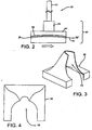
- each welding wire container is essentially identical and positioned about a top periphery of each container in a mirror image fashion, the dome having at least a partial cut-out portion 48 sufficiently sized for access of guide conduit 28 as well as wire guide conduit transfer component 38 when positioned either In a left-to-right or right-to-left orientation when wire guide conduit transfer component 38 is positioned thereupon and affixed to shaft 40 ( Fig. 2 ).
- Fig. 7 one wishbone aperture is illustrated which permits the alignment described hereinbefore. However, when multiple containers are employed with the optional tops or domes, it is recognized that multiple wishbone apertures would be positioned about the center of the top or dome.
- wire guide transfer component 38 includes top plate 42 with wire transfer plate 44 affixed thereto, the combination forming fixed wire transfer plate 46 which is insertable onto or into shaft 40 using known mechanical affixing methods known to those skilled in the art.
- shaft 40 may be an n-sided shaft (wherein n is at least three) with a mating shaft opening attached to the bottom of top plate 42.
- shaft 40 may be essentially circular with a mating shaft opening attached to the bottom of top plate 42 and wherein rotation Is inhibited by the inclusion of a set screw.
- Yet another approach involves the concept of a notched rest.
- the top of wire transfer plate 44 has a retention groove 52 through which welding wire 50 travels during the cross-over from one welding wire staged container into an in-process container.
- the orientation of groove 52 has been determined to at least play a role in minimizing various possible welding wire tangles, e.g., the tendency of bulk welding wire during payout to form an "e-script" among others. As better illustrated in Fig.
- the wire transfer plate 44 is orientated in anticipation of a left to right transfer, I.e., the in-process coil of wire is positioned to the right and the staged coil of wire Is positioned to the left, and the positioning of groove 52 is from a nearly tangent line running between the outer diameter of the in-process coil of wire and the inner diameter of the staged coil of wire, this positioning determined by the direction of transfer.
- the tangent line described is the natural line which the welding wire takes during the transfer from the just-emptied wire package to the full endless wire package, and which serves to reduce imposed stress energy in the wire transfer loop that often leads to tangling opportunities.
- curved retention groove 52 is oriented in a curvilinear manner in which the direction of the curve is facing outwardly and the inlet and outlets of the curved retention groove are positioned approximately nearly along a tangent line between the outer diameter of the In-process coil of wire and the inner diameter of the staged coil of wire.
- repositioning and turning reversible wire transfer plate 46 by 180° around the pivot point wire payouts which are directioned from right to left are accommodated.
- shaft 40 is vertically positionable and fastenable upon vertical center post 34 to permit different height wire containers.
- the pivot point of reversible wire transfer plate 46 is also vertically adjustable.
- dome 36 is optional and illustrated as generally hemispherical in shape.
- the geometry may be other than hemispherical, and may be rectangular-shaped at a base and more frusto-conical as the dome progresses toward its apex. In either shape, dome 36 will have an apertured side in which cut-out 48 extends from a top of the dome to the base of the dome.
- a transfer system is illustrated in which no domes are positioned upon the bulk wire dispensing containers, the containers either having no lids or partial lids which have appropriate cut-outs sufficiently dimensioned to permit the wire to transition between containers.
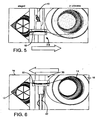
- wire transfer arm 22 is pivotally mounted on vertical center post 34 and has 360° of rotation.
- the arm rotates with bearings. This configuration permits more than two welding wire containers to be pre-positioned and joined in an array about post 34, allowing larger amounts of wire to be run In a continuous fashion with resultant reductions in attendant time for the package setup technician.
- conduit support arm 22 is pivotable about frame 20 into defined and fixed positions by the matching of at least one magnet 60 within bearing block collar 64 and fixed positioning magnets 62 on top of frame column 20.
- This arrangement allows magnetic stops to couple without having to hit a stop and allow the necessary positioning during normal dispensing, but break free to follow the transfer wire. Therefore, as the welding wire is completely dispensed from the in-process coil of wire package, the magnetic force to retain the wire transfer arm over that package is overcome and the arm pivots to a position above what had previously been the staged coil of wire package.
- the sequence for the wire transfer arm is repeated for each successive wire package, illustrated to be approximately 90° In Fig. B.
Landscapes
- Engineering & Computer Science (AREA)
- Physics & Mathematics (AREA)
- Plasma & Fusion (AREA)
- Mechanical Engineering (AREA)
- Unwinding Of Filamentary Materials (AREA)
- Molten Solder (AREA)
Applications Claiming Priority (4)
| Application Number | Priority Date | Filing Date | Title |
|---|---|---|---|
| US201261711558P | 2012-10-09 | 2012-10-09 | |
| US13/826,216 US9421633B2 (en) | 2012-10-09 | 2013-03-14 | Bulk wire delivery system |
| EP13805509.0A EP2885105B1 (de) | 2012-10-09 | 2013-10-09 | Spulendrahtausgabesystem |
| PCT/IB2013/002237 WO2014057336A2 (en) | 2012-10-09 | 2013-10-09 | Bulk wire delivery system |
Related Parent Applications (2)
| Application Number | Title | Priority Date | Filing Date |
|---|---|---|---|
| PCT/IB2013/002237 Previously-Filed-Application WO2014057336A2 (en) | 2012-10-09 | 2013-10-09 | Bulk wire delivery system |
| EP13805509.0A Division EP2885105B1 (de) | 2012-10-09 | 2013-10-09 | Spulendrahtausgabesystem |
Publications (2)
| Publication Number | Publication Date |
|---|---|
| EP3552749A1 true EP3552749A1 (de) | 2019-10-16 |
| EP3552749B1 EP3552749B1 (de) | 2023-05-31 |
Family
ID=50431973
Family Applications (2)
| Application Number | Title | Priority Date | Filing Date |
|---|---|---|---|
| EP13805509.0A Active EP2885105B1 (de) | 2012-10-09 | 2013-10-09 | Spulendrahtausgabesystem |
| EP19151915.6A Active EP3552749B1 (de) | 2012-10-09 | 2013-10-09 | Spulendrahtausgabesystem |
Family Applications Before (1)
| Application Number | Title | Priority Date | Filing Date |
|---|---|---|---|
| EP13805509.0A Active EP2885105B1 (de) | 2012-10-09 | 2013-10-09 | Spulendrahtausgabesystem |
Country Status (8)
| Country | Link |
|---|---|
| US (2) | US9421633B2 (de) |
| EP (2) | EP2885105B1 (de) |
| JP (1) | JP6230610B2 (de) |
| KR (1) | KR102100527B1 (de) |
| CN (1) | CN104736287B (de) |
| BR (1) | BR112015005128A2 (de) |
| PL (2) | PL2885105T3 (de) |
| WO (1) | WO2014057336A2 (de) |
Families Citing this family (9)
| Publication number | Priority date | Publication date | Assignee | Title |
|---|---|---|---|---|
| US9421633B2 (en) * | 2012-10-09 | 2016-08-23 | Lincoln Global, Inc. | Bulk wire delivery system |
| CN109702285B (zh) * | 2017-10-25 | 2021-07-16 | 宝山钢铁股份有限公司 | 一种焊丝送丝装置 |
| CN109436933A (zh) * | 2018-12-29 | 2019-03-08 | 乐庭电线工业(惠州)有限公司 | 应用于中拉机上的换线装置 |
| WO2022047013A1 (en) * | 2020-08-27 | 2022-03-03 | American Linc, Llc | Canister-yarn tensioning assembly incorporating a pivoted yarn tensioner |
| US12606409B1 (en) * | 2020-12-23 | 2026-04-21 | A.B. Carter, Inc. | Canister-yarn tensioning assembly incorporating a pivoted yarn tensioner |
| USD991299S1 (en) | 2021-04-30 | 2023-07-04 | Esab Ab | Hood for a welding consumable container |
| USD998664S1 (en) | 2021-04-30 | 2023-09-12 | Esab Ab | Welding consumable container |
| USD998665S1 (en) | 2021-04-30 | 2023-09-12 | Esab Ab | Welding consumable container |
| CN113213247A (zh) * | 2021-05-21 | 2021-08-06 | 菲翼汽车电气(上海)有限公司 | 一种导线上料机构、方法和送线设备 |
Citations (2)
| Publication number | Priority date | Publication date | Assignee | Title |
|---|---|---|---|---|
| US20100072317A1 (en) | 2007-01-03 | 2010-03-25 | Elco Enterprises, Inc. | Wire dispensing system |
| EP2174741A1 (de) * | 2008-10-07 | 2010-04-14 | SIDERGAS Spa | Abdeckung für einen Schweißdrahtbehälter |
Family Cites Families (30)
| Publication number | Priority date | Publication date | Assignee | Title |
|---|---|---|---|---|
| US1955805A (en) | 1930-11-12 | 1934-04-24 | Western Electric Co | Guarding and guiding apparatus |
| US2774548A (en) | 1953-02-04 | 1956-12-18 | Western Electric Co | Wire payoff apparatus |
| US2942802A (en) * | 1955-08-30 | 1960-06-28 | Western Electric Co | Transfer device for guiding strand as it is continuously unwound from spools |
| US2944755A (en) * | 1959-01-05 | 1960-07-12 | Western Electric Co | Cut-over mechanism for advancing strands |
| US3780963A (en) * | 1971-11-09 | 1973-12-25 | Krupp Gmbh | Wire-looping apparatus |
| US4097004A (en) * | 1977-05-06 | 1978-06-27 | Ppg Industries, Inc. | Method and apparatus for unwinding roving packages from the inside |
| JPS58147962U (ja) * | 1982-03-27 | 1983-10-04 | 日鐵溶接工業株式会社 | 溶接用ワイヤの装填装置 |
| JPS59229287A (ja) | 1983-06-10 | 1984-12-22 | Nippon Steel Weld Prod & Eng Co Ltd | 溶接用ワイヤの装填物 |
| JPS60177155A (ja) * | 1984-02-23 | 1985-09-11 | Tanaka Kikinzoku Kogyo Kk | 装飾用黄金色系銅合金 |
| US4572458A (en) * | 1984-11-14 | 1986-02-25 | American Barmag Corporation | Compact creel for large diameter yarn supply packages |
| US4578513A (en) * | 1984-11-16 | 1986-03-25 | American Cyanamid Company | Process for preparing phenylisopropylurea compounds |
| JPH0215893Y2 (de) | 1985-03-25 | 1990-04-27 | ||
| JPH0716687Y2 (ja) * | 1989-06-20 | 1995-04-19 | 松下電器産業株式会社 | 溶接用ワイヤ収納ペイル容器 |
| JP2991018B2 (ja) * | 1993-11-19 | 1999-12-20 | 松下電器産業株式会社 | 溶接用ワイヤ収納ペイル容器 |
| US5816514A (en) * | 1997-01-15 | 1998-10-06 | Reliance Electrice Industrial Company | Wire supply assembly |
| US5971308A (en) | 1998-03-04 | 1999-10-26 | National-Standard Company | Wire transfer assembly |
| JP2001025868A (ja) * | 1999-07-12 | 2001-01-30 | Daido Steel Co Ltd | ワイヤ引出し装置 |
| SE0101749L (sv) * | 2001-05-18 | 2002-04-23 | Esab Ab | Anordning vid svetstrådsmatning, trådorienteringslöpare, metod och användning |
| JP2003019560A (ja) | 2001-07-05 | 2003-01-21 | Kawasaki Steel Corp | ペイルパック巻溶接用ワイヤの払出し治具 |
| US7441721B2 (en) * | 2002-06-17 | 2008-10-28 | Hyundai Welding Co., Ltd. | Device for preventing welding wire from tangling |
| US7615718B2 (en) * | 2003-05-30 | 2009-11-10 | Toyota Moto Engineering & Manufacturing North America, Inc. | Apparatus and method for supplying a continuous source of wire |
| US7041932B2 (en) | 2003-05-30 | 2006-05-09 | Toyota Motor Manufacturing North America, Inc. | Apparatus and method for supplying a continuous source of wire |
| US7220942B2 (en) | 2004-09-30 | 2007-05-22 | Lincoln Global, Inc. | Feeder for endless welding wire |
| DE102005018566A1 (de) * | 2005-04-21 | 2006-10-26 | Sidergas Spa | Abdeckung für einen Schweißdrahtbehälter |
| US7309038B2 (en) | 2005-05-27 | 2007-12-18 | Lincoln Global, Inc. | Endless wire container and method of using the same |
| FR2893588B1 (fr) * | 2005-11-21 | 2008-02-01 | Airbus France Sas | Case de train a structure en caissons |
| US20070175965A1 (en) | 2006-02-02 | 2007-08-02 | Lincoln Global, Inc. | System and method of providing endless welding wire |
| JP5198424B2 (ja) * | 2009-12-25 | 2013-05-15 | 株式会社神戸製鋼所 | ペイルパック用押さえ部材、ペイルパック用容器及び溶接ワイヤ収納ペイルパック |
| JP5511405B2 (ja) * | 2010-01-25 | 2014-06-04 | 株式会社ダイヘン | 溶接ワイヤ送給装置および溶接装置 |
| US9421633B2 (en) * | 2012-10-09 | 2016-08-23 | Lincoln Global, Inc. | Bulk wire delivery system |
-
2013
- 2013-03-14 US US13/826,216 patent/US9421633B2/en active Active
- 2013-10-09 WO PCT/IB2013/002237 patent/WO2014057336A2/en not_active Ceased
- 2013-10-09 JP JP2015535118A patent/JP6230610B2/ja active Active
- 2013-10-09 PL PL13805509T patent/PL2885105T3/pl unknown
- 2013-10-09 EP EP13805509.0A patent/EP2885105B1/de active Active
- 2013-10-09 PL PL19151915.6T patent/PL3552749T3/pl unknown
- 2013-10-09 KR KR1020157008897A patent/KR102100527B1/ko active Active
- 2013-10-09 BR BR112015005128A patent/BR112015005128A2/pt not_active IP Right Cessation
- 2013-10-09 CN CN201380052858.6A patent/CN104736287B/zh active Active
- 2013-10-09 EP EP19151915.6A patent/EP3552749B1/de active Active
-
2016
- 2016-08-18 US US15/239,905 patent/US9868610B2/en active Active
Patent Citations (2)
| Publication number | Priority date | Publication date | Assignee | Title |
|---|---|---|---|---|
| US20100072317A1 (en) | 2007-01-03 | 2010-03-25 | Elco Enterprises, Inc. | Wire dispensing system |
| EP2174741A1 (de) * | 2008-10-07 | 2010-04-14 | SIDERGAS Spa | Abdeckung für einen Schweißdrahtbehälter |
Also Published As
| Publication number | Publication date |
|---|---|
| US9868610B2 (en) | 2018-01-16 |
| EP2885105A2 (de) | 2015-06-24 |
| KR102100527B1 (ko) | 2020-04-14 |
| EP3552749B1 (de) | 2023-05-31 |
| CN104736287B (zh) | 2017-08-15 |
| BR112015005128A2 (pt) | 2017-07-04 |
| US20140097287A1 (en) | 2014-04-10 |
| CN104736287A (zh) | 2015-06-24 |
| WO2014057336A3 (en) | 2014-07-31 |
| EP2885105B1 (de) | 2019-01-16 |
| KR20150067174A (ko) | 2015-06-17 |
| US9421633B2 (en) | 2016-08-23 |
| JP6230610B2 (ja) | 2017-11-15 |
| US20160355368A1 (en) | 2016-12-08 |
| JP2015530261A (ja) | 2015-10-15 |
| PL3552749T3 (pl) | 2023-09-11 |
| PL2885105T3 (pl) | 2019-07-31 |
| WO2014057336A2 (en) | 2014-04-17 |
Similar Documents
| Publication | Publication Date | Title |
|---|---|---|
| EP3552749B1 (de) | Spulendrahtausgabesystem | |
| US5971308A (en) | Wire transfer assembly | |
| CA2694456C (en) | Wire guide insert and method for drum package payoff | |
| EP2168706A1 (de) | Halter für einen Schweißdrahtbehälter mit flexiblen Klappen; Kombination von Schweissdrahtbund und einem solchen Halter | |
| US9809413B2 (en) | Winding device for strand shaped winding material | |
| WO2013074512A1 (en) | Floating dispensing mechanism for drum packed welding wire with a de-coil conduit | |
| EP2830810A1 (de) | Schweissdrahtvorschub mit drahtführung mit voneinander beabstandeten verlängerten führungsflächen | |
| CN105908294B (zh) | 供纱筒管方向转换装置以及筒管供给系统 | |
| JP2014076904A (ja) | リング精紡機において製造された紡績コップを、後続の巻返し過程のために準備する方法 | |
| CN205602813U (zh) | 改进型弹簧钢丝放线器 | |
| EP4282800B1 (de) | Förderer für garnzufuhrpackung | |
| JPH1126985A (ja) | 回路部品供給方法および供給システム | |
| CN203209583U (zh) | 焊丝用矫正装置 | |
| JP5831391B2 (ja) | 線材供給装置 | |
| EP2522610B1 (de) | Garnwickelvorrichtung | |
| CN108406268A (zh) | 一种入轴机 | |
| US10370213B2 (en) | Device for winding strip-shaped material | |
| CN1216513A (zh) | 用于纺织纤维生产设备的纱线筒子贮运装置 | |
| CN108529331B (zh) | 绕线机 | |
| US20240367215A1 (en) | Coil spring product with rotary cutter | |
| CN109023628A (zh) | 一种微细金属丝用整经筒子架 | |
| EP2512013A1 (de) | Drahtführung zum Aufwickeln von Draht auf einem Stator- oder Ständerkern, insbesondere für Drähte mit einem relativ großen Durchmesser | |
| EP4385929A1 (de) | Spulengatterroboter und system | |
| KR102372126B1 (ko) | 연속냉간압연용 벤딩 롤 제조장치 | |
| JP7823008B2 (ja) | 物品保持具 |
Legal Events
| Date | Code | Title | Description |
|---|---|---|---|
| PUAI | Public reference made under article 153(3) epc to a published international application that has entered the european phase |
Free format text: ORIGINAL CODE: 0009012 |
|
| STAA | Information on the status of an ep patent application or granted ep patent |
Free format text: STATUS: THE APPLICATION HAS BEEN PUBLISHED |
|
| AC | Divisional application: reference to earlier application |
Ref document number: 2885105 Country of ref document: EP Kind code of ref document: P |
|
| AK | Designated contracting states |
Kind code of ref document: A1 Designated state(s): AL AT BE BG CH CY CZ DE DK EE ES FI FR GB GR HR HU IE IS IT LI LT LU LV MC MK MT NL NO PL PT RO RS SE SI SK SM TR |
|
| STAA | Information on the status of an ep patent application or granted ep patent |
Free format text: STATUS: REQUEST FOR EXAMINATION WAS MADE |
|
| 17P | Request for examination filed |
Effective date: 20200416 |
|
| RBV | Designated contracting states (corrected) |
Designated state(s): AL AT BE BG CH CY CZ DE DK EE ES FI FR GB GR HR HU IE IS IT LI LT LU LV MC MK MT NL NO PL PT RO RS SE SI SK SM TR |
|
| STAA | Information on the status of an ep patent application or granted ep patent |
Free format text: STATUS: EXAMINATION IS IN PROGRESS |
|
| 17Q | First examination report despatched |
Effective date: 20201022 |
|
| GRAP | Despatch of communication of intention to grant a patent |
Free format text: ORIGINAL CODE: EPIDOSNIGR1 |
|
| STAA | Information on the status of an ep patent application or granted ep patent |
Free format text: STATUS: GRANT OF PATENT IS INTENDED |
|
| INTG | Intention to grant announced |
Effective date: 20220519 |
|
| GRAJ | Information related to disapproval of communication of intention to grant by the applicant or resumption of examination proceedings by the epo deleted |
Free format text: ORIGINAL CODE: EPIDOSDIGR1 |
|
| STAA | Information on the status of an ep patent application or granted ep patent |
Free format text: STATUS: EXAMINATION IS IN PROGRESS |
|
| INTC | Intention to grant announced (deleted) | ||
| GRAP | Despatch of communication of intention to grant a patent |
Free format text: ORIGINAL CODE: EPIDOSNIGR1 |
|
| STAA | Information on the status of an ep patent application or granted ep patent |
Free format text: STATUS: GRANT OF PATENT IS INTENDED |
|
| INTG | Intention to grant announced |
Effective date: 20221209 |
|
| GRAS | Grant fee paid |
Free format text: ORIGINAL CODE: EPIDOSNIGR3 |
|
| GRAA | (expected) grant |
Free format text: ORIGINAL CODE: 0009210 |
|
| STAA | Information on the status of an ep patent application or granted ep patent |
Free format text: STATUS: THE PATENT HAS BEEN GRANTED |
|
| AC | Divisional application: reference to earlier application |
Ref document number: 2885105 Country of ref document: EP Kind code of ref document: P |
|
| AK | Designated contracting states |
Kind code of ref document: B1 Designated state(s): AL AT BE BG CH CY CZ DE DK EE ES FI FR GB GR HR HU IE IS IT LI LT LU LV MC MK MT NL NO PL PT RO RS SE SI SK SM TR |
|
| REG | Reference to a national code |
Ref country code: GB Ref legal event code: FG4D Ref country code: CH Ref legal event code: EP |
|
| REG | Reference to a national code |
Ref country code: DE Ref legal event code: R096 Ref document number: 602013083883 Country of ref document: DE |
|
| REG | Reference to a national code |
Ref country code: AT Ref legal event code: REF Ref document number: 1570657 Country of ref document: AT Kind code of ref document: T Effective date: 20230615 |
|
| REG | Reference to a national code |
Ref country code: IE Ref legal event code: FG4D |
|
| REG | Reference to a national code |
Ref country code: SE Ref legal event code: TRGR |
|
| REG | Reference to a national code |
Ref country code: LT Ref legal event code: MG9D |
|
| REG | Reference to a national code |
Ref country code: NL Ref legal event code: MP Effective date: 20230531 |
|
| PG25 | Lapsed in a contracting state [announced via postgrant information from national office to epo] |
Ref country code: NO Free format text: LAPSE BECAUSE OF FAILURE TO SUBMIT A TRANSLATION OF THE DESCRIPTION OR TO PAY THE FEE WITHIN THE PRESCRIBED TIME-LIMIT Effective date: 20230831 Ref country code: ES Free format text: LAPSE BECAUSE OF FAILURE TO SUBMIT A TRANSLATION OF THE DESCRIPTION OR TO PAY THE FEE WITHIN THE PRESCRIBED TIME-LIMIT Effective date: 20230531 |
|
| PG25 | Lapsed in a contracting state [announced via postgrant information from national office to epo] |
Ref country code: RS Free format text: LAPSE BECAUSE OF FAILURE TO SUBMIT A TRANSLATION OF THE DESCRIPTION OR TO PAY THE FEE WITHIN THE PRESCRIBED TIME-LIMIT Effective date: 20230531 Ref country code: NL Free format text: LAPSE BECAUSE OF FAILURE TO SUBMIT A TRANSLATION OF THE DESCRIPTION OR TO PAY THE FEE WITHIN THE PRESCRIBED TIME-LIMIT Effective date: 20230531 Ref country code: LV Free format text: LAPSE BECAUSE OF FAILURE TO SUBMIT A TRANSLATION OF THE DESCRIPTION OR TO PAY THE FEE WITHIN THE PRESCRIBED TIME-LIMIT Effective date: 20230531 Ref country code: LT Free format text: LAPSE BECAUSE OF FAILURE TO SUBMIT A TRANSLATION OF THE DESCRIPTION OR TO PAY THE FEE WITHIN THE PRESCRIBED TIME-LIMIT Effective date: 20230531 Ref country code: IS Free format text: LAPSE BECAUSE OF FAILURE TO SUBMIT A TRANSLATION OF THE DESCRIPTION OR TO PAY THE FEE WITHIN THE PRESCRIBED TIME-LIMIT Effective date: 20230930 Ref country code: HR Free format text: LAPSE BECAUSE OF FAILURE TO SUBMIT A TRANSLATION OF THE DESCRIPTION OR TO PAY THE FEE WITHIN THE PRESCRIBED TIME-LIMIT Effective date: 20230531 Ref country code: GR Free format text: LAPSE BECAUSE OF FAILURE TO SUBMIT A TRANSLATION OF THE DESCRIPTION OR TO PAY THE FEE WITHIN THE PRESCRIBED TIME-LIMIT Effective date: 20230901 |
|
| PG25 | Lapsed in a contracting state [announced via postgrant information from national office to epo] |
Ref country code: FI Free format text: LAPSE BECAUSE OF FAILURE TO SUBMIT A TRANSLATION OF THE DESCRIPTION OR TO PAY THE FEE WITHIN THE PRESCRIBED TIME-LIMIT Effective date: 20230531 |
|
| PG25 | Lapsed in a contracting state [announced via postgrant information from national office to epo] |
Ref country code: SK Free format text: LAPSE BECAUSE OF FAILURE TO SUBMIT A TRANSLATION OF THE DESCRIPTION OR TO PAY THE FEE WITHIN THE PRESCRIBED TIME-LIMIT Effective date: 20230531 |
|
| PG25 | Lapsed in a contracting state [announced via postgrant information from national office to epo] |
Ref country code: SM Free format text: LAPSE BECAUSE OF FAILURE TO SUBMIT A TRANSLATION OF THE DESCRIPTION OR TO PAY THE FEE WITHIN THE PRESCRIBED TIME-LIMIT Effective date: 20230531 Ref country code: SK Free format text: LAPSE BECAUSE OF FAILURE TO SUBMIT A TRANSLATION OF THE DESCRIPTION OR TO PAY THE FEE WITHIN THE PRESCRIBED TIME-LIMIT Effective date: 20230531 Ref country code: RO Free format text: LAPSE BECAUSE OF FAILURE TO SUBMIT A TRANSLATION OF THE DESCRIPTION OR TO PAY THE FEE WITHIN THE PRESCRIBED TIME-LIMIT Effective date: 20230531 Ref country code: PT Free format text: LAPSE BECAUSE OF FAILURE TO SUBMIT A TRANSLATION OF THE DESCRIPTION OR TO PAY THE FEE WITHIN THE PRESCRIBED TIME-LIMIT Effective date: 20231002 Ref country code: EE Free format text: LAPSE BECAUSE OF FAILURE TO SUBMIT A TRANSLATION OF THE DESCRIPTION OR TO PAY THE FEE WITHIN THE PRESCRIBED TIME-LIMIT Effective date: 20230531 Ref country code: DK Free format text: LAPSE BECAUSE OF FAILURE TO SUBMIT A TRANSLATION OF THE DESCRIPTION OR TO PAY THE FEE WITHIN THE PRESCRIBED TIME-LIMIT Effective date: 20230531 |
|
| REG | Reference to a national code |
Ref country code: DE Ref legal event code: R097 Ref document number: 602013083883 Country of ref document: DE |
|
| PLBE | No opposition filed within time limit |
Free format text: ORIGINAL CODE: 0009261 |
|
| STAA | Information on the status of an ep patent application or granted ep patent |
Free format text: STATUS: NO OPPOSITION FILED WITHIN TIME LIMIT |
|
| PG25 | Lapsed in a contracting state [announced via postgrant information from national office to epo] |
Ref country code: SI Free format text: LAPSE BECAUSE OF FAILURE TO SUBMIT A TRANSLATION OF THE DESCRIPTION OR TO PAY THE FEE WITHIN THE PRESCRIBED TIME-LIMIT Effective date: 20230531 |
|
| 26N | No opposition filed |
Effective date: 20240301 |
|
| PG25 | Lapsed in a contracting state [announced via postgrant information from national office to epo] |
Ref country code: SI Free format text: LAPSE BECAUSE OF FAILURE TO SUBMIT A TRANSLATION OF THE DESCRIPTION OR TO PAY THE FEE WITHIN THE PRESCRIBED TIME-LIMIT Effective date: 20230531 Ref country code: MC Free format text: LAPSE BECAUSE OF FAILURE TO SUBMIT A TRANSLATION OF THE DESCRIPTION OR TO PAY THE FEE WITHIN THE PRESCRIBED TIME-LIMIT Effective date: 20230531 |
|
| REG | Reference to a national code |
Ref country code: CH Ref legal event code: PL |
|
| REG | Reference to a national code |
Ref country code: AT Ref legal event code: UEP Ref document number: 1570657 Country of ref document: AT Kind code of ref document: T Effective date: 20230531 |
|
| REG | Reference to a national code |
Ref country code: BE Ref legal event code: MM Effective date: 20231031 |
|
| PG25 | Lapsed in a contracting state [announced via postgrant information from national office to epo] |
Ref country code: LU Free format text: LAPSE BECAUSE OF NON-PAYMENT OF DUE FEES Effective date: 20231009 |
|
| GBPC | Gb: european patent ceased through non-payment of renewal fee |
Effective date: 20231009 |
|
| PG25 | Lapsed in a contracting state [announced via postgrant information from national office to epo] |
Ref country code: LU Free format text: LAPSE BECAUSE OF NON-PAYMENT OF DUE FEES Effective date: 20231009 |
|
| PG25 | Lapsed in a contracting state [announced via postgrant information from national office to epo] |
Ref country code: GB Free format text: LAPSE BECAUSE OF NON-PAYMENT OF DUE FEES Effective date: 20231009 |
|
| PG25 | Lapsed in a contracting state [announced via postgrant information from national office to epo] |
Ref country code: CH Free format text: LAPSE BECAUSE OF NON-PAYMENT OF DUE FEES Effective date: 20231031 |
|
| PG25 | Lapsed in a contracting state [announced via postgrant information from national office to epo] |
Ref country code: GB Free format text: LAPSE BECAUSE OF NON-PAYMENT OF DUE FEES Effective date: 20231009 Ref country code: FR Free format text: LAPSE BECAUSE OF NON-PAYMENT OF DUE FEES Effective date: 20231031 Ref country code: CH Free format text: LAPSE BECAUSE OF NON-PAYMENT OF DUE FEES Effective date: 20231031 |
|
| PG25 | Lapsed in a contracting state [announced via postgrant information from national office to epo] |
Ref country code: BE Free format text: LAPSE BECAUSE OF NON-PAYMENT OF DUE FEES Effective date: 20231031 |
|
| PG25 | Lapsed in a contracting state [announced via postgrant information from national office to epo] |
Ref country code: IE Free format text: LAPSE BECAUSE OF NON-PAYMENT OF DUE FEES Effective date: 20231009 |
|
| PG25 | Lapsed in a contracting state [announced via postgrant information from national office to epo] |
Ref country code: IE Free format text: LAPSE BECAUSE OF NON-PAYMENT OF DUE FEES Effective date: 20231009 |
|
| PG25 | Lapsed in a contracting state [announced via postgrant information from national office to epo] |
Ref country code: BG Free format text: LAPSE BECAUSE OF FAILURE TO SUBMIT A TRANSLATION OF THE DESCRIPTION OR TO PAY THE FEE WITHIN THE PRESCRIBED TIME-LIMIT Effective date: 20230531 |
|
| PG25 | Lapsed in a contracting state [announced via postgrant information from national office to epo] |
Ref country code: BG Free format text: LAPSE BECAUSE OF FAILURE TO SUBMIT A TRANSLATION OF THE DESCRIPTION OR TO PAY THE FEE WITHIN THE PRESCRIBED TIME-LIMIT Effective date: 20230531 |
|
| PG25 | Lapsed in a contracting state [announced via postgrant information from national office to epo] |
Ref country code: CY Free format text: LAPSE BECAUSE OF FAILURE TO SUBMIT A TRANSLATION OF THE DESCRIPTION OR TO PAY THE FEE WITHIN THE PRESCRIBED TIME-LIMIT; INVALID AB INITIO Effective date: 20131009 |
|
| PG25 | Lapsed in a contracting state [announced via postgrant information from national office to epo] |
Ref country code: HU Free format text: LAPSE BECAUSE OF FAILURE TO SUBMIT A TRANSLATION OF THE DESCRIPTION OR TO PAY THE FEE WITHIN THE PRESCRIBED TIME-LIMIT; INVALID AB INITIO Effective date: 20131009 |
|
| PGFP | Annual fee paid to national office [announced via postgrant information from national office to epo] |
Ref country code: PL Payment date: 20250930 Year of fee payment: 13 |
|
| PGFP | Annual fee paid to national office [announced via postgrant information from national office to epo] |
Ref country code: CZ Payment date: 20250926 Year of fee payment: 13 |
|
| PG25 | Lapsed in a contracting state [announced via postgrant information from national office to epo] |
Ref country code: TR Free format text: LAPSE BECAUSE OF FAILURE TO SUBMIT A TRANSLATION OF THE DESCRIPTION OR TO PAY THE FEE WITHIN THE PRESCRIBED TIME-LIMIT Effective date: 20230531 |
|
| PGFP | Annual fee paid to national office [announced via postgrant information from national office to epo] |
Ref country code: DE Payment date: 20251020 Year of fee payment: 13 |
|
| PGFP | Annual fee paid to national office [announced via postgrant information from national office to epo] |
Ref country code: AT Payment date: 20251021 Year of fee payment: 13 |
|
| PGFP | Annual fee paid to national office [announced via postgrant information from national office to epo] |
Ref country code: IT Payment date: 20251031 Year of fee payment: 13 |
|
| PGFP | Annual fee paid to national office [announced via postgrant information from national office to epo] |
Ref country code: SE Payment date: 20251023 Year of fee payment: 13 |