EP4151333B1 - Herstellung von schraubenfedern mit einem rotationsschneider - Google Patents
Herstellung von schraubenfedern mit einem rotationsschneider Download PDFInfo
- Publication number
- EP4151333B1 EP4151333B1 EP21197470.4A EP21197470A EP4151333B1 EP 4151333 B1 EP4151333 B1 EP 4151333B1 EP 21197470 A EP21197470 A EP 21197470A EP 4151333 B1 EP4151333 B1 EP 4151333B1
- Authority
- EP
- European Patent Office
- Prior art keywords
- wire
- winding stage
- stage
- deformed
- rotary cutter
- Prior art date
- Legal status (The legal status is an assumption and is not a legal conclusion. Google has not performed a legal analysis and makes no representation as to the accuracy of the status listed.)
- Active
Links
Images




Classifications
-
- B—PERFORMING OPERATIONS; TRANSPORTING
- B21—MECHANICAL METAL-WORKING WITHOUT ESSENTIALLY REMOVING MATERIAL; PUNCHING METAL
- B21F—WORKING OR PROCESSING OF METAL WIRE
- B21F11/00—Cutting wire
- B21F11/005—Cutting wire springs
-
- B—PERFORMING OPERATIONS; TRANSPORTING
- B21—MECHANICAL METAL-WORKING WITHOUT ESSENTIALLY REMOVING MATERIAL; PUNCHING METAL
- B21F—WORKING OR PROCESSING OF METAL WIRE
- B21F23/00—Feeding wire in wire-working machines or apparatus
-
- B—PERFORMING OPERATIONS; TRANSPORTING
- B21—MECHANICAL METAL-WORKING WITHOUT ESSENTIALLY REMOVING MATERIAL; PUNCHING METAL
- B21F—WORKING OR PROCESSING OF METAL WIRE
- B21F3/00—Coiling wire into particular forms
- B21F3/02—Coiling wire into particular forms helically
- B21F3/04—Coiling wire into particular forms helically externally on a mandrel or the like
-
- B—PERFORMING OPERATIONS; TRANSPORTING
- B21—MECHANICAL METAL-WORKING WITHOUT ESSENTIALLY REMOVING MATERIAL; PUNCHING METAL
- B21F—WORKING OR PROCESSING OF METAL WIRE
- B21F35/00—Making springs from wire
Definitions
- the present invention relates to a mechanism for producing coil springs and to a method of producing coil springs.
- Mattresses, sofas or other bedding or seating furniture may be provided with innerspring units formed of coil springs.
- Such coil springs may for example be combined in a wire framework or may be enclosed by fabric to form an assembly of pocket springs.
- the present invention provides a mechanism according to claim 1, and a method according to claim 13.
- the dependent claims define further embodiments.
- an embodiment of the invention provides a mechanism for producing coil springs.
- the mechanism comprises a winding stage for engaging with a wire and deforming the wire to coil windings as the wire moves through the winding stage. Further, the mechanism comprises a feed mechanism configured to feed the wire to the winding stage. Further, the mechanism comprises a rotary cutter. The rotary cutter is configured to cut the deformed wire into portions forming separate coil springs and a blade which is driven for rotation about a stationary rotation axis. Accordingly, cutting of the wire can be achieved without requiring an excessively complex cutting mechanism.
- the feed mechanism is configured to maintain a constant speed of feeding the wire while the rotary cutter cuts the deformed wire.
- the coil springs can thus be formed in an efficient manner, without requiring stoppage or slowing of the feeding speed.
- the feed mechanism could also be configured to operate in a single-step or intermittent manner.
- the mechanism further comprises a mandrel for cooperating with the blade to cut the wire.
- the mandrel may be arranged centrally within the coil spring being formed and thus also act as a guide or support for the coil spring being formed.
- a position of the mandrel relative to the rotation axis of the blade may be adjustable.
- a position of the rotary cutter relative to the winding stage may be adjustable. In this way, the mechanism may be adapted to different wire gauges and/or geometries of the wire being formed.
- the blade comprises a protrusion configured to engage between two coil windings of the deformed wire and separate the two coil windings as the blade rotates. In this way, it can be efficiently ensured that the deformed wire is cut at a desired position, taking into account that at an end portion of the coil spring there may be coil windings in close vicinity.
- the blade is formed on a terminal surface of a shaft portion driven to rotate about the rotation axis.
- the blade can thus be formed in a simple and robust manner. A need for a complex drive mechanism can be avoided.
- the winding stage comprises at least one bending tool, typically two or more bending tools. Such one or more bending tools engage the wire at positions set according to a geometry of the coil springs.
- the winding stage may then be configured to maintain engagement of the bending tools with the deformed wire while the rotary cutter cuts the deformed wire. In this way, cutting of the wire may be performed while keeping the deformed wire in a well-defined position.
- the least one bending tool may be driven to move the wire to a position in which the rotary cutter cuts the deformed wire.
- the at least one bending tool may be driven to move during the process of winding the wire, thereby conveying a desired geometry to the coil spring being produced.
- the at least one bending tool may be driven to move the deformed wire towards the rotary cutter, so that the wire can be cut at a well-defined position. This movement may at the same time assist in producing the coil spring with more densely arranged coils at its end.
- the mechanism may further comprise an output stage for transferring the coil springs from the mechanism.
- the output stage may comprise a guide element for guiding movement of the deformed wire in the winding stage and towards a transport mechanism.
- the guide element may for example have V-shaped surfaces for engaging on an outer periphery of the coil spring being formed, so that coil springs of various geometry can be guided in a reliable manner.
- the transport mechanism may comprises at least one magnetic carrier for engaging with the deformed wire and moving the coil spring from the winding stage.
- the output stage may be configured to cause engagement of the at least one magnetic carrier with the deformed wire before the deformed wire is cut by the rotary cutter to release the coil spring being produced.
- a method for producing coil springs is provided.
- the method is implemented by a mechanism according to any one of the above embodiments.
- the method comprises:
- a constant speed of feeding the wire to the winding stage may be maintained while cutting the deformed wire.
- the method may further comprise heating the wire before feeding the wire to the winding stage.
- the method may further comprise maintaining engagement of bending tools of the winding stage with the deformed wire while the rotary cutter cuts the deformed wire.
- the method may further comprise guiding movement of the deformed wire in the winding stage and towards a transport mechanism.
- the transport mechanism may comprises at least one magnetic carrier for engaging with the deformed wire and moving the coil spring from the winding stage.
- the method may comprise causing engagement of the at least one magnetic carrier with the deformed wire before the deformed wire is cut by the rotary cutter to release the coil spring being produced.
- Exemplary embodiments of the invention as explained in the following relate to a mechanism for producing coil springs.
- the mechanism may for example be part of or be used in connection with an assembly machine for innerspring units.
- innerspring units may be based on coil springs connected in a wire framework or on coil springs enclosed by fabric to form an assembly of pocket springs.
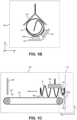
- Figs. 1A , 1B , 1C , and 2 schematically illustrate a mechanism 100 for producing coil springs 10.
- Fig. 1A shows a plan view in an x-y plane, which may for example correspond to a vertical plane.
- Fig. 1B shows a further plan view in an x-y plane, which is offset from the illustration plane of Fig. 1A .
- Fig. 1C illustrates a plan view in an y-z plane, which is perpendicular to the illustration planes of Figs. 1A and 1B .
- Fig. 2 shows a perspective view of elements of the mechanism 100.
- the mechanism 100 includes a winding stage 110, a feeding stage 120, a rotary cutter 130, a heating stage 140, and an output stage 150.
- the winding stage 110 deforms a wire 20, e.g., steel wire, to coil windings.
- the winding stage 110 is provided with bending tools 115.
- the bending tools 115 engage the wire 20 at positions which are set according to the desired geometry of coil springs 10 to be produced by the mechanism 100.
- the bending tools 115 may be motor-driven or be driven by some other kind of drive mechanism, e.g., by a cam drive, so that the positions of engaging the wire 20 can be controlled in an automated manner.
- the mechanism 100 is provided with a feeding stage 120.
- the feeding stage 120 feeds the wire 20 to the winding stage 110.
- the feeding stage 120 is assumed to be provided with two pairs of driven rollers 125. However, it is noted that utilization of only one pair of driven rollers 125 or utilization of more than two pairs of driven rollers 125 would be possible as well.
- the wire 20 is engaged between the two rollers 125 of each pair, so that rotation of the rollers 125 pushes the wire 20 into the winding stage 110.
- a guide element 126 is provided at an interface of the feeding stage 120 to the winding stage 110, so that the winding stage 110 receives the wire 20 in a well-defined position.
- the feeding stage 120 feeds the wire 20 at constant speed to the winding stage 110, so that the wire 20 is pushed through the winding stage 110, where it is engaged by the bending tools 115 and thus deformed to the coil windings.
- the mechanism 100 is provided with a rotary cutter 130.
- the rotary cutter 130 is arranged in the vicinity of the winding stage 110 so that the rotary cutter 130 can cut the wire 20 deformed in the winding stage 110.
- the rotary cutter 130 is based on a blade 135 which is fixedly mounted on a rotary shaft 136 rotates about a stationary rotation axis 135X.
- This rotation axis 135X is substantially parallel to the axis of the coil springs 10 being produced, which in the illustrated example corresponds to the z-axis.
- the rotating blade 135 cooperates with a mandrel 137. As for example illustrated in Fig. 1C , the deformed wire 20 passes between the mandrel 137 and the rotating cutting blade 135.
- one or more of the bending tools 115 may be motor-driven. In this way, the spatial position at which the bending tool 115 engages the wire 20 can be changed during the winding process to thereby obtain a desired geometry of the coil spring 10 being produced. Further, the bending tool 115 can be driven towards the rotary cutter 130, so that the rotary cutter 130 can cut the wire 20 at a desired position. As can for example be seen from Figs. 1A and 1C , the rotating blade 135 of the rotary cutter 130 may rotate about an axis extending in the z-direction, so that the cutting edge 139 moves along a circular trajectory in the x-y-plane.
- the bending tool 115 which is closest to the rotary cutter 130 may move along the z-direction, e.g., to vary the pitch of the coil windings. In some cases, the bending tool 115 may also move within the x-y-plane, e.g., to vary the diameter of the coil windings. At the end of the winding process, the bending tool 115 may move the wire 20 towards the rotary cutter 130, so that it intersects with the trajectory of the cutting edge 139. In this way, the wire 20 can be cut at a well-defined position. Further, the movement of the bending tool 115 may help to produce more densely arranged coil windings at the end of the coil spring 10.
- the speed of rotation of the blade 135 may be set in accordance with the constant speed of feeding the wire 20 to the winding stage 110, so that for feeding a wire portion corresponding to one coil spring 10 there is one revolution of the blade 135.
- the blade 135 may rotate at constant speed.
- the mechanism 100 may be provided with a heating stage 140.
- the heating stage 140 may be used to heat the wire 20 before it is fed to the winding stage 110. Accordingly, deformation of the wire 20 in the winding stage 20 may be assisted and controlled by heating the wire 20.
- the heating stage 140 is provided with a number of heaters 141, e.g., based on injecting electric current via electrodes, which heat the wire 20 due to electrical resistance of the wire 20.
- other types of heater could be used as alternative or in addition, e.g., inductive heaters.
- the heating stage 140 is provided with guide elements 142 for guiding the wire 20 through the heating stage 140 while avoiding undesired deformation of the wire.
- the geometry of the heating stage 140 shown in Fig. 1A is merely exemplary and that other geometries could be used as well, e.g., with a higher or lower number of heaters 141 or with a different arrangement of the heaters 141.
- the mechanism 100 may also be provided with an output stage 150 which actively transfers the coil springs 10 from the winding stage 110.
- the output stage 150 includes a transport mechanism 160 which transports the coil springs 10 substantially along an axis of the coil springs 10 being produced.
- the transport mechanism 160 may for example transport the coil springs towards another component of an innerspring assembly machine, e.g., a pocketing mechanism which inserts the coil springs 10 into pockets of fabric material or an assembly mechanism which connects the coil springs 10 in a wire framework.
- the transport mechanism 160 includes magnetic carriers 165 which are each driven by a belt drive 161 along a transport direction of the coil springs 10.
- the magnetic carriers 165 magnetically engage with the coil spring 10 being produced. As illustrated in Fig. 1C , this engagement occurs before the rotary cutter 130 cuts the deformed wire 20 and the coil spring 10 is released from the wire 20 fed to the winding stage 110. In this way, undesired movement of the coil spring 10 being produced can be avoided and the coil spring 10 thus reliably transferred from the winding stage 110.
- magnetic engagement of the magnetic carriers 165 with the coil spring 10 being produced can occur synchronously with or after the rotary cutter 130 cuts the deformed wire 20 and the coil spring 10 is released from the wire 20 fed to the winding stage 110.
- the number of the magnetic carriers 165 is two, each being driven by a separate belt drive 161.
- the magnetic carriers 165 and corresponding belt drives 161 may be arranged to engage different portions of the coil spring 10 being produced, e.g., the two end portions of the coil spring 10 or one end portion and a central portion of the coil spring 10.
- other numbers of magnetic carriers 165 could be used as well, e.g., only one magnetic carrier.
- other types of transport mechanism could also be used in the output stage 150, e.g., a transport mechanism based on a magnetic conveyor belt or a transport mechanism based on a non-magnetic carrier.
- a stop 156 may be provided for stopping movement of the coil springs 10 by the transport mechanism 160. While the transport mechanism 160 transfers the coil spring 10 from the winding stage 110, the next coil spring 10 is already being formed in the winding stage 110.
- the output stage 150 is provides with a guide element 155.
- the guide element 155 is formed with V-shaped surfaces for engaging on an outer periphery of the coil spring 10 being produced.
- the guide element 155 guides movement of the deformed wire 20 coming from the winding stage 110 towards the transport mechanism 160.
- the position of the guide element 155 relative to the winding stage 110 and to the transport mechanism 160 may be adjustable to allow precise adaptation to different geometries of the coil springs 10 being produced.
- Fig. does not illustrate elements of the rotary cutter 130 and Figs. 1B and 1C do not illustrate the bending tools 115 of the winding stage 110.
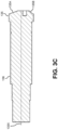
- Figs. 3A, 3B , and 3C further illustrate an exemplary implementation of the blade 135 of the rotary cutter 130.
- Fig. 3A shows a perspective view of the blade 135 and the rotary shaft 136 of the blade 135.
- Fig. 3B shows a plan view of the blade 135, taken in a plane perpendicular to the rotation axis of the blade 135.
- Fig. 3C shows a sectional view of the rotary shaft 136 and the blade 135, taken along line A-A of Fig. 3B .
- the blade 135 is formed on a terminal surface of the rotary shaft 136.
- the rotary shaft 136 and the blade 135 are thus formed as a unitary component. Rotation of the blade 135 about the rotation axis 135X can thus be directly driven by the rotary shaft 136.
- a protrusion 138 is formed on a peripheral portion of the blade 135. In a radial direction from the rotation axis 135X, the protrusion 138 extends further outward from the cutting edge 139 of the blade 135. During rotation of the blade 135, the protrusion engages between two coil windings of the deformed wire 20 and separate the two coil windings, while the cutting edge 139 cuts the deformed wire 20 in one of these coil windings. This situation is schematically illustrated in Fig. 1C .
- the rotational speed of the blade 135 when cutting the deformed wire 20 is set in such a way that velocity of the cutting edge 139 exceeds the speed of feeding the wire 20, which in turn defines the velocity of the wire portion being cut.
- the blade 135 is provided with slanted outer surfaces 135A and 135B. These slanted outer surfaces 135A, 135B may be formed in a thread-like shape. The slanted outer surfaces 135A, 135B may help to avoid that the rotating blade 135 interferes with the coil spring 10 being formed in the winding stage 110. Further, the slanted outer surfaces 135A, 135B may guide the deformed wire 20, so that the coil winding in which cutting is to be performed is reliably brought into contact with the cutting edge 139.
- Fig. 4 shows a flowchart for schematically illustrating a method of producing coil springs, such as the above-mentioned coil springs 10. The method may for example be performed by the above-mentioned mechanism 130.
- a wire is feed to a winding stage, e.g., like explained above for the feeding of the wire 20 to the winding stage 110.
- the wire may be heated or unheated.
- the feeding of the wire to the winding stage is performed at constant speed.
- the feeding of the wire to the winding stage could be accomplished in a single-step manner, e.g., by feeding a wire portion corresponding to one coil spring into the winding stage and then stopping the feeding until producing the next coil spring, or in an intermittent manner, e.g., by stopping the feeding of the wire also during production of the coil spring.
- the wire is engaged in the winding stage to deform the wire to coil windings as the wire moves through the winding stage.
- the wire can be engaged by one, two, or more bending tools of the winding stage, such as the above-mentioned bending tools 115.
- One or more of such bending tools may be motor-driven, so that the position of engaging the wire can be changed in the course of the winding process.
- the deformed wire is cut into portions forming separate coil springs, such as the above-mentioned coil springs 10.
- the cutting of the wire is performed by a blade rotating about a stationary rotation axis, such as explained for the above-mentioned blade 135 which rotates about rotation axis 135X. While cutting the deformed wire, the constant speed of feeding the wire to the winding stage can be maintained. The cutting of the deformed wire produces a separate portion of the deformed wire 20, corresponding to a single coil spring. When cutting the deformed wire, the engagement of the deformed wire with one or more bending tools of the winding stage may be maintained.
- the bending tool engaging the wire may be driven to move the wire to a position in which the rotary cutter cuts the deformed wire.
- such bending tool may be driven to move during the process of winding the wire, thereby conveying a desired geometry to the coil spring being produced.
- the bending tool may be driven to move the deformed wire towards the rotary cutter, so that the wire can be cut at a well-defined position. This movement may at the same time assist in producing the coil spring with more densely arranged coils at its end.
- the coil spring produced at step 430 is transferred from the winding stage.
- a transport mechanism such as the above-mentioned transport mechanism 160.
- the transport mechanism may use one or more carriers for engaging with a portion of the coil spring and moving the coil spring from the winding stage 110, such as the above-mentioned carriers 165.
- the one or more carriers may be magnetic or non-magnetic.
- a guide element may guide movement of the deformed wire in the winding stage and towards the transport mechanism. As for example explained for the above-mentioned guide element 155, the guide element may have V-shaped surfaces for engaging on an outer periphery of the coil spring. Engagement of the one or more carriers with the deformed wire may occur before the deformed wire is cut by the rotating blade.
- the illustrated mechanism and method may be used to produce various kinds of coil springs, e.g., barrel-shaped coil springs, cylindrically shaped coil springs, or hourglass shaped coil springs.
- the produced coil springs may have various kinds of geometries, e.g., various coil winding diameters, various pitches, various heights, or the like.
- the bending tools used in the winding stage may be selected and configured according to the specific type and geometry of coil spring to be produced.
- the output stage may provide an interface to various other kind of machinery processing or otherwise handling coil springs, e.g., machinery for producing innerspring units.
- Such innerspring units may consist of pocket springs formed by enclosing the coil springs in fabric material or coil springs connected in an open wire framework.
Landscapes
- Engineering & Computer Science (AREA)
- Mechanical Engineering (AREA)
- Wire Processing (AREA)
Claims (13)
- Mechanismus (100) zum Herstellen von Schraubenfedern (10), wobei der Mechanismus (100) umfasst:eine Wickelstufe (110) zum in Eingriff Bringen eines Drahts (20) und zum Verformen des Drahtes (20) zu Spulenwindungen, wenn sich der Draht (20) durch die Wickelstufe (110) bewegt;einen Vorschubmechanismus (120), der ausgestaltet ist, um den Draht (20) der Wickelstufe (110) zuzuführen; undeinen Rotationsschneider (130), der ausgestaltet ist, um den verformten Draht (20) in Abschnitte zu schneiden, die separate Schraubenfedern (10) bilden,wobei der Rotationsschneider (130) eine Klinge (135) umfasst, die zur Rotation um eine stationäre Rotationsachse (135X) angetrieben wird,dadurch gekennzeichnet,dass die Klinge (135) einen Vorsprung (138) umfasst, der ausgestaltet ist, um zwischen zwei Spulenwindungen des verformten Drahts (20) in Eingriff zu kommen und die beiden Spulenwindungen zu trennen, wenn die Klinge (135) rotiert.
- Mechanismus (100) nach Anspruch 1,
wobei der Vorschubmechanismus (120) ausgestaltet ist, um eine konstante Geschwindigkeit für den Vorschub des Drahtes (20) beizubehalten, während der Rotationsschneider (130) den verformten Draht (20) schneidet. - Mechanismus (100) nach Anspruch 1 oder 2, darüber hinaus umfassend:
einen Dorn (137) zum Zusammenwirken mit der Klinge (135), um den Draht (20) zu schneiden. - Mechanismus (100) nach Anspruch 3,
wobei eine Position des Dorns (137) relativ zu der Rotationsachse (135X) einstellbar ist. - Mechanismus (100) nach einem der vorhergehenden Ansprüche,
wobei eine Position des Rotationsschneiders (130) relativ zu der Wickelstufe (110) einstellbar ist. - Mechanismus (100) nach einem der vorhergehenden Ansprüche,
wobei die Klinge (135) an einer Endfläche eines Wellenabschnitts (136) ausgebildet ist, der zur Rotation um die Rotationsachse (135X) angetrieben wird. - Mechanismus (100) nach einem der vorhergehenden Ansprüche,wobei die Wickelstufe (110) mindestens ein Biegewerkzeug (115) umfasst, das den Draht (20) an Positionen in Eingriff bringt, die entsprechend einer Geometrie der herzustellenden Schraubenfedern (10) eingestellt sind,wobei die Wickelstufe (110) ausgestaltet ist, um den Eingriff des mindestens einen Biegewerkzeugs (115) mit dem verformten Draht (20) aufrechtzuerhalten, während der Rotationsschneider (130) den verformten Draht (20) schneidet.
- Mechanismus (100) nach einem der vorhergehenden Ansprüche,
wobei das mindestens eine Biegewerkzeug (115) angetrieben wird, um den Draht (20) in eine Position zu bewegen, in der der Rotationsschneider (130) den verformten Draht (20) schneidet. - Mechanismus (100) nach einem der vorhergehenden Ansprüche, der darüber hinaus umfasst:
eine Heizstufe (140), die ausgestaltet ist, um den Draht (20) vor dem Einführen in die Wickelstufe (110) zu erwärmen. - Mechanismus (100) nach einem der vorangehenden Ansprüche, der darüber hinaus umfasst: eine Ausgabestufe (150) zur Übergabe der Schraubenfedern (10) von dem Mechanismus (100),
wobei die Ausgabestufe (150) ein Führungselement (155) zum Führen einer Bewegung des verformten Drahtes (20) in der Wickelstufe (110) und in Richtung eines Transportmechanismus (160) umfasst. - Mechanismus (100) nach einem der vorhergehenden Ansprüche,
wobei der Transportmechanismus (160) mindestens einen magnetischen Träger (165) umfasst, um mit dem verformten Draht (20) in Eingriff zu kommen und die Schraubenfeder (10) von der Wickelstufe (110) zu bewegen. - Mechanismus (100) nach Anspruch 11,
wobei die Ausgabestufe (150) ausgestaltet ist, um einen Eingriff des mindestens einen Magnetträgers (165) mit dem verformten Draht (20) zu bewirken, bevor der verformte Draht (20) von dem Rotationsschneider (130) geschnitten wird, um die hergestellte Schraubenfeder (10) freizugeben. - Verfahren zum Herstellen von Schraubenfedern (10), wobei das Verfahren umfasst:- Zuführen eines Drahtes (20) zu einer Wickelstufe (110);- in Eingriff Bringen des Drahtes (20) in der Wickelstufe (110), um den Draht (20) zu Schraubenwindungen zu verformen, wenn sich der Draht (20) durch die Wickelstufe (110) bewegt; und- Schneiden des verformten Drahtes (20) in Abschnitte, die separate Schraubenfedern (10) bilden, durch eine Klinge (135), die um eine stationäre Rotationsachse (135X) rotiert,dadurch gekennzeichnet,
dass das Verfahren durch einen Mechanismus (100) nach einem der Ansprüche 1 bis 12 durchgeführt wird.
Priority Applications (9)
| Application Number | Priority Date | Filing Date | Title |
|---|---|---|---|
| EP21197470.4A EP4151333B1 (de) | 2021-09-17 | 2021-09-17 | Herstellung von schraubenfedern mit einem rotationsschneider |
| HRP20241167TT HRP20241167T1 (hr) | 2021-09-17 | 2021-09-17 | Proizvodnja zavojnih opruga s rotirajućim rezačem |
| PL21197470.4T PL4151333T3 (pl) | 2021-09-17 | 2021-09-17 | Produkcja sprężyn śrubowych z wykorzystaniem noża obrotowego |
| DK21197470.4T DK4151333T3 (da) | 2021-09-17 | 2021-09-17 | Produktion af spilralfjedre med roterende skærer |
| US18/689,673 US20240367215A1 (en) | 2021-09-17 | 2022-09-15 | Coil spring product with rotary cutter |
| CN202280061557.9A CN117940231A (zh) | 2021-09-17 | 2022-09-15 | 利用旋转刀具生产螺旋弹簧 |
| MX2024003261A MX2024003261A (es) | 2021-09-17 | 2022-09-15 | Produccion de muelles helicoidales con cortadora rotativa. |
| CA3225392A CA3225392A1 (en) | 2021-09-17 | 2022-09-15 | Coil spring production with rotary cutter |
| PCT/EP2022/075604 WO2023041620A1 (en) | 2021-09-17 | 2022-09-15 | Coil spring production with rotary cutter |
Applications Claiming Priority (1)
| Application Number | Priority Date | Filing Date | Title |
|---|---|---|---|
| EP21197470.4A EP4151333B1 (de) | 2021-09-17 | 2021-09-17 | Herstellung von schraubenfedern mit einem rotationsschneider |
Publications (2)
| Publication Number | Publication Date |
|---|---|
| EP4151333A1 EP4151333A1 (de) | 2023-03-22 |
| EP4151333B1 true EP4151333B1 (de) | 2024-07-24 |
Family
ID=78085764
Family Applications (1)
| Application Number | Title | Priority Date | Filing Date |
|---|---|---|---|
| EP21197470.4A Active EP4151333B1 (de) | 2021-09-17 | 2021-09-17 | Herstellung von schraubenfedern mit einem rotationsschneider |
Country Status (9)
| Country | Link |
|---|---|
| US (1) | US20240367215A1 (de) |
| EP (1) | EP4151333B1 (de) |
| CN (1) | CN117940231A (de) |
| CA (1) | CA3225392A1 (de) |
| DK (1) | DK4151333T3 (de) |
| HR (1) | HRP20241167T1 (de) |
| MX (1) | MX2024003261A (de) |
| PL (1) | PL4151333T3 (de) |
| WO (1) | WO2023041620A1 (de) |
Families Citing this family (1)
| Publication number | Priority date | Publication date | Assignee | Title |
|---|---|---|---|---|
| CN118877517B (zh) * | 2024-09-29 | 2024-12-13 | 泰州市铭昊精密合金制品有限公司 | 一种镍铬合金电热丝加工制造用上料运输设备 |
Family Cites Families (13)
| Publication number | Priority date | Publication date | Assignee | Title |
|---|---|---|---|---|
| US2869640A (en) * | 1954-04-05 | 1959-01-20 | Stephen A Platt | Travelling wire coil cutter |
| US4986103A (en) * | 1990-05-08 | 1991-01-22 | Newcomb Spring Corp. | Apparatus for coiling springs with tucked ends |
| DE4040659C1 (en) * | 1990-12-19 | 1992-02-20 | Wafios Maschinenfabrik Gmbh & Co Kg, 7410 Reutlingen, De | Metal spring coiling machine - incorporates wire feed, coiling tools and cutter |
| US5454249A (en) * | 1992-06-19 | 1995-10-03 | Reell Precision Manufacturing Corporation | Spring toe forming device and method |
| JP4693211B2 (ja) * | 2000-07-31 | 2011-06-01 | 中央発條株式会社 | 傾斜コイルばねの製造方法 |
| CN2523574Y (zh) * | 2001-12-31 | 2002-12-04 | 厦门莱宝机械有限公司 | 单刀片固定切边强制分离器 |
| FR2937890B1 (fr) * | 2008-11-05 | 2010-12-24 | Ressorts Huon Dubois | Procede et installation de fabrication d'un ressort |
| DE102012204513B3 (de) * | 2012-03-21 | 2013-09-19 | Wafios Ag | Verfahren und Vorrichtung zur Herstellung von Schraubenfedern durch Federwinden |
| JP6148148B2 (ja) | 2013-10-18 | 2017-06-14 | 日本発條株式会社 | ばね成形装置および成形方法 |
| GB201609642D0 (en) * | 2016-06-02 | 2016-07-20 | Harrison Spinks Components Ltd | Wire shaping apparatus and method |
| JP7258545B2 (ja) * | 2018-12-28 | 2023-04-17 | 日本発條株式会社 | コイリングマシンと、コイルばねの製造方法 |
| CN110238329A (zh) * | 2019-07-08 | 2019-09-17 | 昆山升甫电子制品有限公司 | 一种热卷弹簧成形系统 |
| CN213591655U (zh) * | 2020-08-19 | 2021-07-02 | 浙江华剑智能装备股份有限公司 | 弹簧制造装置 |
-
2021
- 2021-09-17 PL PL21197470.4T patent/PL4151333T3/pl unknown
- 2021-09-17 HR HRP20241167TT patent/HRP20241167T1/hr unknown
- 2021-09-17 EP EP21197470.4A patent/EP4151333B1/de active Active
- 2021-09-17 DK DK21197470.4T patent/DK4151333T3/da active
-
2022
- 2022-09-15 WO PCT/EP2022/075604 patent/WO2023041620A1/en not_active Ceased
- 2022-09-15 US US18/689,673 patent/US20240367215A1/en active Pending
- 2022-09-15 CN CN202280061557.9A patent/CN117940231A/zh active Pending
- 2022-09-15 CA CA3225392A patent/CA3225392A1/en active Pending
- 2022-09-15 MX MX2024003261A patent/MX2024003261A/es unknown
Also Published As
| Publication number | Publication date |
|---|---|
| WO2023041620A1 (en) | 2023-03-23 |
| DK4151333T3 (da) | 2024-08-12 |
| EP4151333A1 (de) | 2023-03-22 |
| PL4151333T3 (pl) | 2024-11-18 |
| HRP20241167T1 (hr) | 2024-11-22 |
| CN117940231A (zh) | 2024-04-26 |
| CA3225392A1 (en) | 2023-03-23 |
| US20240367215A1 (en) | 2024-11-07 |
| MX2024003261A (es) | 2024-04-03 |
Similar Documents
| Publication | Publication Date | Title |
|---|---|---|
| US11018563B2 (en) | Manufacturing apparatus and manufacturing method of electrical rotating machine | |
| US4909057A (en) | Apparatus and methods for continuously forming edgewise wound cores | |
| EP0044464B1 (de) | Verfahren zum Formen einer Schraubenfeder | |
| EP2677527A1 (de) | Wickelvorrichtung und Wickelverfahren für hochkantige Spule | |
| EP1461172B1 (de) | Maschine und verfahren zur herstellung einer doppeldrahtfeder | |
| CN103008499A (zh) | 数控线圈机和使用数控线圈机连续加工线圈的方法 | |
| WO2014152953A1 (en) | Innerspring manufacturing and assembly system and components for selectable coil orientation, position adjustment and coil conveyance | |
| US4296543A (en) | Method of and apparatus for fabricating stator assemblies of electrical machines | |
| US20240367215A1 (en) | Coil spring product with rotary cutter | |
| US4914934A (en) | Method of forming an edgewise wound core | |
| EP1327295A1 (de) | Maschine zum wickeln dynamoelektrischer statoren | |
| US6792673B2 (en) | Apparatus for forming a hollow cylindrical dynamo-electric machine stator core | |
| EP0198047B1 (de) | Aus einem stanzstreifen bestehende anordnung | |
| BR112024001014B1 (pt) | Produção de molas helicoidais com cortador rotativo | |
| JP2895054B1 (ja) | ピン打ち機 | |
| WO2024201148A1 (en) | Method and winding machine for making an electric component provided with a spiral-shaped winding | |
| US4643012A (en) | Apparatus for forming edgewise wound cores | |
| US4233728A (en) | Methods for making and using slot closure wedges at a coil injection station | |
| US4918962A (en) | Apparatus and method for forming edgewise wound cores | |
| KR20150047227A (ko) | 진공증착코일용 보조스프링 성형기 | |
| CN224115049U (zh) | 卷簧机 | |
| EP3463712B1 (de) | Drahtformungsvorrichtung und verfahren zur formung eines drahts | |
| JP3807902B2 (ja) | 棒材供給機 | |
| KR940001999A (ko) | 쉐이디드 폴 인덕션 모터(Shaded pole induction moter)의 고정자(core)에 쉐이딩코일(Shading coil)을 용접하기 위한 자동용접장치 | |
| JP6442737B2 (ja) | コイルの巻線方法および巻線装置 |
Legal Events
| Date | Code | Title | Description |
|---|---|---|---|
| REG | Reference to a national code |
Ref country code: HR Ref legal event code: TUEP Ref document number: P20241167T Country of ref document: HR |
|
| PUAI | Public reference made under article 153(3) epc to a published international application that has entered the european phase |
Free format text: ORIGINAL CODE: 0009012 |
|
| STAA | Information on the status of an ep patent application or granted ep patent |
Free format text: STATUS: THE APPLICATION HAS BEEN PUBLISHED |
|
| AK | Designated contracting states |
Kind code of ref document: A1 Designated state(s): AL AT BE BG CH CY CZ DE DK EE ES FI FR GB GR HR HU IE IS IT LI LT LU LV MC MK MT NL NO PL PT RO RS SE SI SK SM TR |
|
| STAA | Information on the status of an ep patent application or granted ep patent |
Free format text: STATUS: REQUEST FOR EXAMINATION WAS MADE |
|
| P01 | Opt-out of the competence of the unified patent court (upc) registered |
Effective date: 20230523 |
|
| 17P | Request for examination filed |
Effective date: 20230607 |
|
| RBV | Designated contracting states (corrected) |
Designated state(s): AL AT BE BG CH CY CZ DE DK EE ES FI FR GB GR HR HU IE IS IT LI LT LU LV MC MK MT NL NO PL PT RO RS SE SI SK SM TR |
|
| STAA | Information on the status of an ep patent application or granted ep patent |
Free format text: STATUS: EXAMINATION IS IN PROGRESS |
|
| 17Q | First examination report despatched |
Effective date: 20231018 |
|
| GRAP | Despatch of communication of intention to grant a patent |
Free format text: ORIGINAL CODE: EPIDOSNIGR1 |
|
| STAA | Information on the status of an ep patent application or granted ep patent |
Free format text: STATUS: GRANT OF PATENT IS INTENDED |
|
| INTG | Intention to grant announced |
Effective date: 20240409 |
|
| GRAS | Grant fee paid |
Free format text: ORIGINAL CODE: EPIDOSNIGR3 |
|
| GRAA | (expected) grant |
Free format text: ORIGINAL CODE: 0009210 |
|
| STAA | Information on the status of an ep patent application or granted ep patent |
Free format text: STATUS: THE PATENT HAS BEEN GRANTED |
|
| AK | Designated contracting states |
Kind code of ref document: B1 Designated state(s): AL AT BE BG CH CY CZ DE DK EE ES FI FR GB GR HR HU IE IS IT LI LT LU LV MC MK MT NL NO PL PT RO RS SE SI SK SM TR |
|
| REG | Reference to a national code |
Ref country code: GB Ref legal event code: FG4D |
|
| REG | Reference to a national code |
Ref country code: CH Ref legal event code: EP |
|
| REG | Reference to a national code |
Ref country code: DE Ref legal event code: R096 Ref document number: 602021016044 Country of ref document: DE |
|
| REG | Reference to a national code |
Ref country code: DK Ref legal event code: T3 Effective date: 20240808 |
|
| REG | Reference to a national code |
Ref country code: IE Ref legal event code: FG4D |
|
| REG | Reference to a national code |
Ref country code: HR Ref legal event code: ODRP Ref document number: P20241167T Country of ref document: HR Payment date: 20240902 Year of fee payment: 4 |
|
| REG | Reference to a national code |
Ref country code: LT Ref legal event code: MG9D |
|
| REG | Reference to a national code |
Ref country code: HR Ref legal event code: T1PR Ref document number: P20241167 Country of ref document: HR |
|
| REG | Reference to a national code |
Ref country code: NL Ref legal event code: MP Effective date: 20240724 |
|
| PG25 | Lapsed in a contracting state [announced via postgrant information from national office to epo] |
Ref country code: PT Free format text: LAPSE BECAUSE OF FAILURE TO SUBMIT A TRANSLATION OF THE DESCRIPTION OR TO PAY THE FEE WITHIN THE PRESCRIBED TIME-LIMIT Effective date: 20241125 |
|
| REG | Reference to a national code |
Ref country code: AT Ref legal event code: MK05 Ref document number: 1705855 Country of ref document: AT Kind code of ref document: T Effective date: 20240724 |
|
| PG25 | Lapsed in a contracting state [announced via postgrant information from national office to epo] |
Ref country code: NL Free format text: LAPSE BECAUSE OF FAILURE TO SUBMIT A TRANSLATION OF THE DESCRIPTION OR TO PAY THE FEE WITHIN THE PRESCRIBED TIME-LIMIT Effective date: 20240724 |
|
| PG25 | Lapsed in a contracting state [announced via postgrant information from national office to epo] |
Ref country code: PT Free format text: LAPSE BECAUSE OF FAILURE TO SUBMIT A TRANSLATION OF THE DESCRIPTION OR TO PAY THE FEE WITHIN THE PRESCRIBED TIME-LIMIT Effective date: 20241125 Ref country code: NL Free format text: LAPSE BECAUSE OF FAILURE TO SUBMIT A TRANSLATION OF THE DESCRIPTION OR TO PAY THE FEE WITHIN THE PRESCRIBED TIME-LIMIT Effective date: 20240724 |
|
| PG25 | Lapsed in a contracting state [announced via postgrant information from national office to epo] |
Ref country code: NO Free format text: LAPSE BECAUSE OF FAILURE TO SUBMIT A TRANSLATION OF THE DESCRIPTION OR TO PAY THE FEE WITHIN THE PRESCRIBED TIME-LIMIT Effective date: 20241024 |
|
| PG25 | Lapsed in a contracting state [announced via postgrant information from national office to epo] |
Ref country code: FI Free format text: LAPSE BECAUSE OF FAILURE TO SUBMIT A TRANSLATION OF THE DESCRIPTION OR TO PAY THE FEE WITHIN THE PRESCRIBED TIME-LIMIT Effective date: 20240724 Ref country code: GR Free format text: LAPSE BECAUSE OF FAILURE TO SUBMIT A TRANSLATION OF THE DESCRIPTION OR TO PAY THE FEE WITHIN THE PRESCRIBED TIME-LIMIT Effective date: 20241025 |
|
| PG25 | Lapsed in a contracting state [announced via postgrant information from national office to epo] |
Ref country code: BG Free format text: LAPSE BECAUSE OF FAILURE TO SUBMIT A TRANSLATION OF THE DESCRIPTION OR TO PAY THE FEE WITHIN THE PRESCRIBED TIME-LIMIT Effective date: 20240724 |
|
| PG25 | Lapsed in a contracting state [announced via postgrant information from national office to epo] |
Ref country code: LV Free format text: LAPSE BECAUSE OF FAILURE TO SUBMIT A TRANSLATION OF THE DESCRIPTION OR TO PAY THE FEE WITHIN THE PRESCRIBED TIME-LIMIT Effective date: 20240724 |
|
| PG25 | Lapsed in a contracting state [announced via postgrant information from national office to epo] |
Ref country code: IS Free format text: LAPSE BECAUSE OF FAILURE TO SUBMIT A TRANSLATION OF THE DESCRIPTION OR TO PAY THE FEE WITHIN THE PRESCRIBED TIME-LIMIT Effective date: 20241124 Ref country code: AT Free format text: LAPSE BECAUSE OF FAILURE TO SUBMIT A TRANSLATION OF THE DESCRIPTION OR TO PAY THE FEE WITHIN THE PRESCRIBED TIME-LIMIT Effective date: 20240724 |
|
| PG25 | Lapsed in a contracting state [announced via postgrant information from national office to epo] |
Ref country code: RS Free format text: LAPSE BECAUSE OF FAILURE TO SUBMIT A TRANSLATION OF THE DESCRIPTION OR TO PAY THE FEE WITHIN THE PRESCRIBED TIME-LIMIT Effective date: 20241024 Ref country code: ES Free format text: LAPSE BECAUSE OF FAILURE TO SUBMIT A TRANSLATION OF THE DESCRIPTION OR TO PAY THE FEE WITHIN THE PRESCRIBED TIME-LIMIT Effective date: 20240724 |
|
| PG25 | Lapsed in a contracting state [announced via postgrant information from national office to epo] |
Ref country code: RS Free format text: LAPSE BECAUSE OF FAILURE TO SUBMIT A TRANSLATION OF THE DESCRIPTION OR TO PAY THE FEE WITHIN THE PRESCRIBED TIME-LIMIT Effective date: 20241024 Ref country code: NO Free format text: LAPSE BECAUSE OF FAILURE TO SUBMIT A TRANSLATION OF THE DESCRIPTION OR TO PAY THE FEE WITHIN THE PRESCRIBED TIME-LIMIT Effective date: 20241024 Ref country code: LV Free format text: LAPSE BECAUSE OF FAILURE TO SUBMIT A TRANSLATION OF THE DESCRIPTION OR TO PAY THE FEE WITHIN THE PRESCRIBED TIME-LIMIT Effective date: 20240724 Ref country code: IS Free format text: LAPSE BECAUSE OF FAILURE TO SUBMIT A TRANSLATION OF THE DESCRIPTION OR TO PAY THE FEE WITHIN THE PRESCRIBED TIME-LIMIT Effective date: 20241124 Ref country code: GR Free format text: LAPSE BECAUSE OF FAILURE TO SUBMIT A TRANSLATION OF THE DESCRIPTION OR TO PAY THE FEE WITHIN THE PRESCRIBED TIME-LIMIT Effective date: 20241025 Ref country code: FI Free format text: LAPSE BECAUSE OF FAILURE TO SUBMIT A TRANSLATION OF THE DESCRIPTION OR TO PAY THE FEE WITHIN THE PRESCRIBED TIME-LIMIT Effective date: 20240724 Ref country code: ES Free format text: LAPSE BECAUSE OF FAILURE TO SUBMIT A TRANSLATION OF THE DESCRIPTION OR TO PAY THE FEE WITHIN THE PRESCRIBED TIME-LIMIT Effective date: 20240724 Ref country code: BG Free format text: LAPSE BECAUSE OF FAILURE TO SUBMIT A TRANSLATION OF THE DESCRIPTION OR TO PAY THE FEE WITHIN THE PRESCRIBED TIME-LIMIT Effective date: 20240724 Ref country code: AT Free format text: LAPSE BECAUSE OF FAILURE TO SUBMIT A TRANSLATION OF THE DESCRIPTION OR TO PAY THE FEE WITHIN THE PRESCRIBED TIME-LIMIT Effective date: 20240724 |
|
| PG25 | Lapsed in a contracting state [announced via postgrant information from national office to epo] |
Ref country code: RO Free format text: LAPSE BECAUSE OF FAILURE TO SUBMIT A TRANSLATION OF THE DESCRIPTION OR TO PAY THE FEE WITHIN THE PRESCRIBED TIME-LIMIT Effective date: 20240724 Ref country code: SM Free format text: LAPSE BECAUSE OF FAILURE TO SUBMIT A TRANSLATION OF THE DESCRIPTION OR TO PAY THE FEE WITHIN THE PRESCRIBED TIME-LIMIT Effective date: 20240724 |
|
| PG25 | Lapsed in a contracting state [announced via postgrant information from national office to epo] |
Ref country code: MC Free format text: LAPSE BECAUSE OF FAILURE TO SUBMIT A TRANSLATION OF THE DESCRIPTION OR TO PAY THE FEE WITHIN THE PRESCRIBED TIME-LIMIT Effective date: 20240724 Ref country code: EE Free format text: LAPSE BECAUSE OF FAILURE TO SUBMIT A TRANSLATION OF THE DESCRIPTION OR TO PAY THE FEE WITHIN THE PRESCRIBED TIME-LIMIT Effective date: 20240724 |
|
| PG25 | Lapsed in a contracting state [announced via postgrant information from national office to epo] |
Ref country code: CZ Free format text: LAPSE BECAUSE OF FAILURE TO SUBMIT A TRANSLATION OF THE DESCRIPTION OR TO PAY THE FEE WITHIN THE PRESCRIBED TIME-LIMIT Effective date: 20240724 |
|
| REG | Reference to a national code |
Ref country code: DE Ref legal event code: R097 Ref document number: 602021016044 Country of ref document: DE |
|
| PG25 | Lapsed in a contracting state [announced via postgrant information from national office to epo] |
Ref country code: SK Free format text: LAPSE BECAUSE OF FAILURE TO SUBMIT A TRANSLATION OF THE DESCRIPTION OR TO PAY THE FEE WITHIN THE PRESCRIBED TIME-LIMIT Effective date: 20240724 |
|
| PG25 | Lapsed in a contracting state [announced via postgrant information from national office to epo] |
Ref country code: LU Free format text: LAPSE BECAUSE OF NON-PAYMENT OF DUE FEES Effective date: 20240917 |
|
| PLBE | No opposition filed within time limit |
Free format text: ORIGINAL CODE: 0009261 |
|
| STAA | Information on the status of an ep patent application or granted ep patent |
Free format text: STATUS: NO OPPOSITION FILED WITHIN TIME LIMIT |
|
| 26N | No opposition filed |
Effective date: 20250425 |
|
| REG | Reference to a national code |
Ref country code: BE Ref legal event code: MM Effective date: 20240930 |
|
| PG25 | Lapsed in a contracting state [announced via postgrant information from national office to epo] |
Ref country code: BE Free format text: LAPSE BECAUSE OF NON-PAYMENT OF DUE FEES Effective date: 20240930 |
|
| PG25 | Lapsed in a contracting state [announced via postgrant information from national office to epo] |
Ref country code: FR Free format text: LAPSE BECAUSE OF NON-PAYMENT OF DUE FEES Effective date: 20240924 |
|
| PG25 | Lapsed in a contracting state [announced via postgrant information from national office to epo] |
Ref country code: IE Free format text: LAPSE BECAUSE OF NON-PAYMENT OF DUE FEES Effective date: 20240917 |
|
| PG25 | Lapsed in a contracting state [announced via postgrant information from national office to epo] |
Ref country code: SE Free format text: LAPSE BECAUSE OF FAILURE TO SUBMIT A TRANSLATION OF THE DESCRIPTION OR TO PAY THE FEE WITHIN THE PRESCRIBED TIME-LIMIT Effective date: 20240724 |
|
| REG | Reference to a national code |
Ref country code: HR Ref legal event code: ODRP Ref document number: P20241167 Country of ref document: HR Payment date: 20250806 Year of fee payment: 5 |
|
| REG | Reference to a national code |
Ref country code: CH Ref legal event code: U11 Free format text: ST27 STATUS EVENT CODE: U-0-0-U10-U11 (AS PROVIDED BY THE NATIONAL OFFICE) Effective date: 20251001 |
|
| PGFP | Annual fee paid to national office [announced via postgrant information from national office to epo] |
Ref country code: DE Payment date: 20250702 Year of fee payment: 5 Ref country code: DK Payment date: 20250911 Year of fee payment: 5 |
|
| PGFP | Annual fee paid to national office [announced via postgrant information from national office to epo] |
Ref country code: TR Payment date: 20250910 Year of fee payment: 5 Ref country code: PL Payment date: 20250711 Year of fee payment: 5 Ref country code: IT Payment date: 20250825 Year of fee payment: 5 |
|
| PGFP | Annual fee paid to national office [announced via postgrant information from national office to epo] |
Ref country code: GB Payment date: 20250703 Year of fee payment: 5 |
|
| PGFP | Annual fee paid to national office [announced via postgrant information from national office to epo] |
Ref country code: HR Payment date: 20250806 Year of fee payment: 5 |
|
| PGFP | Annual fee paid to national office [announced via postgrant information from national office to epo] |
Ref country code: CH Payment date: 20251001 Year of fee payment: 5 |
|
| PG25 | Lapsed in a contracting state [announced via postgrant information from national office to epo] |
Ref country code: CY Free format text: LAPSE BECAUSE OF FAILURE TO SUBMIT A TRANSLATION OF THE DESCRIPTION OR TO PAY THE FEE WITHIN THE PRESCRIBED TIME-LIMIT; INVALID AB INITIO Effective date: 20210917 |
|
| PG25 | Lapsed in a contracting state [announced via postgrant information from national office to epo] |
Ref country code: HU Free format text: LAPSE BECAUSE OF FAILURE TO SUBMIT A TRANSLATION OF THE DESCRIPTION OR TO PAY THE FEE WITHIN THE PRESCRIBED TIME-LIMIT; INVALID AB INITIO Effective date: 20210917 |
|
| PG25 | Lapsed in a contracting state [announced via postgrant information from national office to epo] |
Ref country code: SI Free format text: LAPSE BECAUSE OF FAILURE TO SUBMIT A TRANSLATION OF THE DESCRIPTION OR TO PAY THE FEE WITHIN THE PRESCRIBED TIME-LIMIT Effective date: 20240724 |
|
| PG25 | Lapsed in a contracting state [announced via postgrant information from national office to epo] |
Ref country code: LT Free format text: LAPSE BECAUSE OF FAILURE TO SUBMIT A TRANSLATION OF THE DESCRIPTION OR TO PAY THE FEE WITHIN THE PRESCRIBED TIME-LIMIT Effective date: 20240724 |