EP3550162A1 - Verfahren zur herstellung eines steigungskabels - Google Patents
Verfahren zur herstellung eines steigungskabels Download PDFInfo
- Publication number
- EP3550162A1 EP3550162A1 EP19172315.4A EP19172315A EP3550162A1 EP 3550162 A1 EP3550162 A1 EP 3550162A1 EP 19172315 A EP19172315 A EP 19172315A EP 3550162 A1 EP3550162 A1 EP 3550162A1
- Authority
- EP
- European Patent Office
- Prior art keywords
- cable
- pitch
- pitch cable
- sleeve
- driver
- Prior art date
- Legal status (The legal status is an assumption and is not a legal conclusion. Google has not performed a legal analysis and makes no representation as to the accuracy of the status listed.)
- Granted
Links
Images


Classifications
-
- F—MECHANICAL ENGINEERING; LIGHTING; HEATING; WEAPONS; BLASTING
- F16—ENGINEERING ELEMENTS AND UNITS; GENERAL MEASURES FOR PRODUCING AND MAINTAINING EFFECTIVE FUNCTIONING OF MACHINES OR INSTALLATIONS; THERMAL INSULATION IN GENERAL
- F16C—SHAFTS; FLEXIBLE SHAFTS; ELEMENTS OR CRANKSHAFT MECHANISMS; ROTARY BODIES OTHER THAN GEARING ELEMENTS; BEARINGS
- F16C1/00—Flexible shafts; Mechanical means for transmitting movement in a flexible sheathing
- F16C1/10—Means for transmitting linear movement in a flexible sheathing, e.g. "Bowden-mechanisms"
- F16C1/12—Arrangements for transmitting movement to or from the flexible member
- F16C1/14—Construction of the end-piece of the flexible member; Attachment thereof to the flexible member
- F16C1/145—Attachment of the end-piece to the flexible member
-
- B—PERFORMING OPERATIONS; TRANSPORTING
- B60—VEHICLES IN GENERAL
- B60J—WINDOWS, WINDSCREENS, NON-FIXED ROOFS, DOORS, OR SIMILAR DEVICES FOR VEHICLES; REMOVABLE EXTERNAL PROTECTIVE COVERINGS SPECIALLY ADAPTED FOR VEHICLES
- B60J7/00—Non-fixed roofs; Roofs with movable panels, e.g. rotary sunroofs
- B60J7/02—Non-fixed roofs; Roofs with movable panels, e.g. rotary sunroofs of sliding type, e.g. comprising guide shoes
- B60J7/04—Non-fixed roofs; Roofs with movable panels, e.g. rotary sunroofs of sliding type, e.g. comprising guide shoes with rigid plate-like element or elements, e.g. open roofs with harmonica-type folding rigid panels
- B60J7/057—Driving or actuating arrangements e.g. manually operated levers or knobs
- B60J7/0573—Driving or actuating arrangements e.g. manually operated levers or knobs power driven arrangements, e.g. electrical
-
- F—MECHANICAL ENGINEERING; LIGHTING; HEATING; WEAPONS; BLASTING
- F16—ENGINEERING ELEMENTS AND UNITS; GENERAL MEASURES FOR PRODUCING AND MAINTAINING EFFECTIVE FUNCTIONING OF MACHINES OR INSTALLATIONS; THERMAL INSULATION IN GENERAL
- F16C—SHAFTS; FLEXIBLE SHAFTS; ELEMENTS OR CRANKSHAFT MECHANISMS; ROTARY BODIES OTHER THAN GEARING ELEMENTS; BEARINGS
- F16C1/00—Flexible shafts; Mechanical means for transmitting movement in a flexible sheathing
- F16C1/10—Means for transmitting linear movement in a flexible sheathing, e.g. "Bowden-mechanisms"
- F16C1/20—Construction of flexible members moved to and fro in the sheathing
-
- F—MECHANICAL ENGINEERING; LIGHTING; HEATING; WEAPONS; BLASTING
- F16—ENGINEERING ELEMENTS AND UNITS; GENERAL MEASURES FOR PRODUCING AND MAINTAINING EFFECTIVE FUNCTIONING OF MACHINES OR INSTALLATIONS; THERMAL INSULATION IN GENERAL
- F16C—SHAFTS; FLEXIBLE SHAFTS; ELEMENTS OR CRANKSHAFT MECHANISMS; ROTARY BODIES OTHER THAN GEARING ELEMENTS; BEARINGS
- F16C2226/00—Joining parts; Fastening; Assembling or mounting parts
- F16C2226/50—Positive connections
- F16C2226/60—Positive connections with threaded parts, e.g. bolt and nut connections
Definitions
- the invention relates to a method for producing a pitch cable, in particular for the operation of sliding roofs or luggage compartment covers of vehicles, to which at a portion of the pitch cable, in particular its one end a driver for power transmission, for example, on sunroofs or cargo space covers of vehicles, are attached.
- Slope cable of the type mentioned which are also known as drive cable or flex shaft, are preferably used in lifting and / or sliding roofs, shading blinds and luggage compartment covers of motor vehicles.
- the pitch cables are axially adjustable, for example, by means of a motor-driven worm and are coupled via a driver to a component to be adjusted, for example to the sunroof, i.
- the drivers also provide the power transmission here.
- the pitch cables are usually made of multi-strand metal cables with applied pitch helices as endless and then have to be cut to the required length.
- the sunroof is coupled on both sides, each with a driver of a pitch cable.
- There are also constructive embodiments are known in which two pitch cables run around the roof opening of the sunroof to a common drive, where they engage with a gear which engages the pitches of the pitch cable and actuates them like a rack.
- the DE 7306 032 U discloses a power window for motor vehicles, wherein by means of a crank-operated gear, a pitch cable is displaced in a longitudinally slotted guide tube at least partially parallel to the direction of movement of the window.
- a driver On the pitch cable a driver is attached.
- the driver can be made of plastic and as a separate, provided with an internal thread part, which is subsequently screwed onto one end of the pitch cable, or be formed as directly sprayed on the pitch cable part.
- drivers on pitch cables of the aforementioned type are also known, which are designed as cast metal casting.
- a pitch cable is described at the one end Driver is attached, which is designed for coupling to a movable in the axial direction of the pitch cable sliding element.
- the driver is cast as around the end of the pitch cable Formed metal body and has a coupling formed for lateral recess, which in the axial direction beyond the end of the Gradient cable is arranged.
- an axially parallel pin is also cast in the remaining in addition to the recess cross-section of the driver.
- pitch cable which consist of plastic and are molded by injection molding around the end of the pitch cable.
- a die-cast carrier which is integrally connected to parts of a carriage body.
- the die-cast support may be attached to a steel cantilever formed as a sheet metal bent part, which forms at least one web and a leg of the carriage body.
- the leg can also be part of the bent sheet metal part.
- the leg is formed there by a plastic part connected to a steel arm, which allows a simple and effective anchoring to the pitch cable by melting by means of ultrasound.
- the plastic part in its region encompassing the pitch cable can preferably be softened by applying ultrasound in such a way that material of the plastic part penetrates into intermediate spaces of the drive cable, which consists, for example, of twisted individual wires.
- the DE 30 15 965 A1 describes an assembly guide for the movement of a sunroof.
- the assembly guide consists of a control cable with a core made of steel wire and a guide body made of plastic, to which a sleeve is formed, in which a soul is attached.
- the soul is with the sleeve train and rotatably welded.
- the FR 2 482 905 A1 discloses a window crank device for the controlled adjustment of movable vehicle windows, with one at an edge portion of a window pane attachable plate and with at least one slidably connected to the plate, arranged parallel to the displacement direction of the window glass guide and connected to the plate via fasteners flexible, the plate along the guide displacing actuator.
- the actuator is formed by a flexible screw spindle, which consists of a flexible metal core and an outer shell.
- the flexible screw spindle extends along a guide tube and engages in a thread formed in a cylindrical sleeve, so that a firm and rigid connection with the plate is made.
- the US 3 444 701 A discloses a mounting bracket with a Bowden cable.
- the Bowden train again consists of an inner wire, which is led through an outer part.
- a shell is formed around the outer part so that there is a firm connection between the outer part and the shell.
- the US 4,570,893 describes a mechanism to adjust the position of an outside mirror of a motor vehicle.
- nut elements are provided in the mirror device within a wall in which run spring parts.
- the nut members and the spring members have corresponding helical shapes. During a movement, ie a rotation of the spring parts, the spring parts can move through the nut elements.
- a pitch cable emerges that has a core consisting of twisted wires.
- the core is wrapped tightly with a helix, which should absorb high forces in the axial direction of the core.
- the core has an end portion which passes through a bore in a bore portion of the driver.
- a stopper body is attached at the end of the core.
- the deformable metal stopper is fixed to the notch on the core at one stroke. It lies with a surface against the end of the bore part, while the other end of the bore part lies against the end of the helix.
- the DE 26 59 268 A1 discloses an end termination of a tensile and compressive force transmitting cable in the form of a sleeve which is screwed onto the cable in the axial direction. Through the union nut in the DE 26 59 268 A1 should be provided a technically simple backup of the final.
- the sleeve is not Part which, during its movement, also sets another part in motion, ie, serves to transmit power.
- the sleeve in the DE 26 59 268 A1 is intended for attachment of the cable end to a main electrical switch of a vehicle.
- the DE 29 12 666 A1 discloses a connection device between a drive cable and a Gleitfuß, which sits slidably in a first guide groove of a fixed part and having a lug, wherein the drive cable is toothed on its surface and displaceable by means of a drive device in the axial direction.
- the drive cable is formed in the approach when forming the Gleitfußes made of plastic, so that the drive cable and the approach are integrally connected.
- the DE 24 18 110 A discloses a Bowden cable consisting of an elongated flexible core with a core and a helically wound wire around the core with spaced turns, with a polymeric material fitting in an array around the core for enclosing the helical wire and core in FIG the areas between successive turns of the helical wire is provided.
- the connector is shaped so that it is disposed around the soul and umbettet the helical wires and the core in the areas between successive turns of the helical wire.
- the DE 10 2010 015 130 A1 discloses a coiled cable drive of a mobile device of a motor vehicle having at least one multi-turn coiled cable connected to a drive means for moving the device via a mechanical operative connection, wherein a drive transducer means converts rotary drive motion of the drive means into translational movement of the coiled cable and wherein the drive transducer means has at least one rotational drive receiving the spindle nut, which surrounds the spiral cable in the region of at least one turn.
- Upon rotation of the spiral nut relative to the spiral cable is caused by a slope of the turns of the spiral cable translational movement of the spiral cable relative to the spindle nut, which is already transmitted by small forces of the spindle nut on the spiral cable.
- a disadvantage of the pitch cables known from the prior art, in particular, is that for each pitch cable to be produced, the driver is cast by injection molding around the end portion of the pitch cable, which represents a not inconsiderable expense against the background of a necessary cost-effective mass production of pitch cables.
- the driver on the pitch cable can be fixed in the form of a bond and / or fusion and / or welding.
- the driver ensures that the driver can initially be formed or produced separately from the pitch cable, as due to the pitch helix of the pitch cable and the corresponding internal thread of the driver screwing the driver on the end of the pitch cable is possible. Only after this process is the actual fixation of the driver.
- the driver is preferably used as a free-falling plastic injection molded part, i. produced by machine as part of a mass production. This fixation is preferably carried out in the form of an ultrasonic welding, gluing, or melting.
- the pitch cable is provided at its second end with a closure sleeve having a bore whose geometry or internal geometry is different from the bore of the driver.
- the end of the pitch cable is processed before connecting to the end sleeve so that the end is at least partially adapted to the corresponding receptacle of the end sleeve.
- the fixation of the driver or the connecting sleeve is preferably carried out by gluing and / or fusing and / or welding.
- a further advantageous embodiment of the invention provides that the driver is fixed by heating, preferably by inductive heating.
- the driver which is expediently made of plastic, is pressed after the heating.
- the driver can first be cold screwed or rotated on a portion of the pitch cable to then heat the driver inductively. After this step, the driver is pressed by means of a pressing tool or a pressing device in tenths of a millimeter range against the pitch cable.
- the joining of the driver and / or the terminating sleeve on the pitch cable can thereby be rotary (screwing) or linear.
- the driver is designed as a plastic injection molded part.
- the schigwinde is formed as a cast. This advantageously ensures that the Kunststoffmit freelance can be made unattended and cost.
- a practicable variant of the invention provides that the pitch cable is provided outside of the driver between the turns of the pitch helix with flocking threads.
- the flocking is advantageously carried out by wrapping or melting of Flockgarnfäden, which consist for example of polyamide and serve to combat noise when moving the pitch cable.
- Such flock yarns for pitch cable are for example from the WO 2009/030376 A1 .
- This fixation is preferably carried out in the form of an ultrasonic welding, gluing, or melting.
- the driver is formed as a metal-plastic component with a molded sheet metal insert, whereby the stability of the driver is further increased.
- the pitch cable is provided with a terminating sleeve at its second end.
- a termination sleeve is in the DE 10 2008 005 983 A1 described.
- the pre-cut pitch cables tend to splice due to the loose strands of the cable.
- Another problem of the known Slope cable is that they tend to rattle in the assembled state at the ends.
- the proposed cover sleeve avoids these disadvantages.
- the cover sleeve has a bore, the wall of which in turn has a shape corresponding to the lead helix.
- the attachment or fixation of the cover sleeve on the slope cable end is done automatically, for example by ultrasonic welding, gluing, or melting.
- the region of the pitch cable, at which the fixation of the driver or the terminating sleeve is to take place is inductively heated prior to the mounting of the driver and / or terminating sleeve.
- the heating of the pitch cable can also be done after the assembly of the driver.
- a depth of engagement of 30 mm is provided, only the range of e.g. 20 mm to 30 mm, starting from one end of the pitch cable, inductively heated, d. that is, in this preferred variant, the end portion of the pitch cable, e.g. 20 mm at the end of the pitch cable is not heated, but only e.g. Heated 10 mm, which are spaced in the range of 20 mm to 30 mm from one end of the pitch cable. A deformation of the driver is thus advantageously avoided.
- the melting or the fusion of pitch cable and driver and / or terminating sleeve serves to fix the driver and / or the terminating sleeve on the pitch cable.
- connection strength or the peel strength between pitch cable and driver is achieved by the screw connection between pitch cable and driver.
- a practicable variant of the invention provides that the fixation of the terminating sleeve takes place on the pitch cable.
- the end of the pitch cable is processed prior to connection to the end sleeve so that the end, the end portion and the tip of the pitch cable is adapted for connection to the end sleeve.
- the shape of the end of the pitch cable can be at least partially adapted to the corresponding receptacle in the end sleeve.
- the end sleeve preferably has a bore with a coherently formed shape.
- a preferably made of plastic end sleeve is mounted so that a fixation can be done by melting the end sleeve on the cable end.
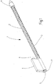
- Fig. 1 shows a pitch cable, which is provided with the reference numeral 1.
- the pitch cable 1 has a core 2, which is formed in the embodiment chosen here from multi-layered in opposite directions superimposed wires, which consist of metal or plastic.
- the pitch cable 1 is how FIG. 1 further illustrated, provided with a arranged at one end driver 4.
- the driver 4 is fixed on the pitch cable 1 and has a bore 5, in which a corresponding to the pitch helix 3 in FIG. 2 shown inner portion 7 is shown in the form of an internal thread is formed.
- the inner portion 7 simultaneously represents the wall of the bore 5.
- FIG. 1 shows further that the pitch cable 1 is provided at its second end with a cover sleeve 6, which forms the conclusion of the pitch cable 1 and to which the pitch cable 1 is attached.
- the cover sleeve 6 has been automatically applied to the pitch cable 1.
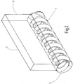
- the in FIG. 2 shown driver 4 is provided with a surface element 8, which, projecting from the driver 4, for coupling with a movable sliding element, such as a sunroof of a motor vehicle, is provided.
- the driver 4 has, as FIG. 2 further illustrates the inner portion 7 in the form of an internal thread, which is formed as a cast.
- the driver 4 as a plastic injection molded part is separated from the in FIG. 1 formed pitch cable 1, ie the in FIG. 1 shown driver 4 is initially not integral part of the pitch cable 1 and separated from the pitch cable 1.
- connection and union of pitch cable 1 and driver 4 is carried out in the context of the method according to the invention, whose course the FIGS. 3a to 3c clarify.
- the method begins with the production of a gradient cable 3 provided with a pitch cable 1 and with the preparation of a provided with a bore 5 driver 4, wherein within the bore 5 a corresponding to the pitch helix 3 inner portion 7 is formed in the form of an internal thread.
- driver 4 is initially not an integral part of the pitch cable 1 and separated from this.
- the in FIG. 3a shown driver 4 is made as a free-falling plastic injection molded part.
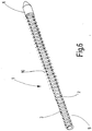
- FIG. 4 shows that in the production of the pitch cable 1, starting from an endless pitch cable, this first, ie before application and fixation of the in FIGS. 3a to 3c shown driver 4, is cut to length. After the pitch cable has been cut to length, how can FIG. 5 illustrates the termination sleeve are automatically applied to one end of the pitch cable 1.
- the pitch cable 1 is wrapped outside of the driver 5 between the turns of the pitch helix 3 of Flockgarnfäden 10, which serves to avoid noise during movement of the pitch cable 1.
- the flock threads 10 are removed.
- the present invention is not limited in its execution to the above-mentioned preferred embodiment. Rather, a number of variants is conceivable, which make use of the solution shown in other types.
Landscapes
- Engineering & Computer Science (AREA)
- General Engineering & Computer Science (AREA)
- Mechanical Engineering (AREA)
- Health & Medical Sciences (AREA)
- Oral & Maxillofacial Surgery (AREA)
- Flexible Shafts (AREA)
- Injection Moulding Of Plastics Or The Like (AREA)
- Ropes Or Cables (AREA)
Abstract
a) Herstellung eines mit einer Steigungswendel versehenen Steigungskabels sowie Herstellung einer mit einer Bohrung versehenen Abschlusshülse, wobei innerhalb der Bohrung eine zu dem zweiten Ende des Steigungskabels korrespondierende Form ausgebildet wird;
b) automatisiertes Fügen der Abschlusshülse auf einen Abschnitt, insbesondere auf ein Ende des Steigungskabels oder automatisiertes Fügen des Steigungskabels in die Bohrung der Abschlusshülse; und
c) Fixierung der Abschlusshülse an einem Abschnitt, insbesondere dem Ende des Steigungskabels, durch Erhitzung des Steigungskabels.
Description
- Die Erfindung betrifft ein Verfahren zur Herstellung eines Steigungskabels, insbesondere für die Betätigung von Schiebedächern oder Laderaumabdeckungen von Fahrzeugen, an dem an einem Abschnitt des Steigungskabels, insbesondere seinem einen Ende ein Mitnehmer zur Kraftübertragung, beispielsweise auf Schiebedächern oder Laderaumabdeckungen von Fahrzeugen, befestigt sind.
- Steigungskabel der eingangs genannten Art, welche auch als Antriebskabel oder Flex-Welle bekannt sind, werden bevorzugt bei Hebe- und/oder Schiebedächern, Beschattungsrollos und Laderaumabdeckungen von Kraftfahrzeugen eingesetzt. Die Steigungskabel sind beispielsweise mittels einer motorangetriebenen Schnecke axial verstellbar und an einem zu verstellenden Bauteil, beispielsweise an dem Schiebedach, über Mitnehmer gekoppelt, d.h. die Mitnehmer sorgen hier auch für die Kraftübertragung. Die Steigungskabel werden meist aus mehreren Litzen bestehenden Metallseilen mit aufgebrachten Steigungswendeln als Endlosware hergestellt und müssen anschließend auf die benötigte Länge abgelängt werden. Das Schiebedach wird dabei an beiden Seiten mit je einem Mitnehmer eines Steigungskabels gekoppelt. Es sind auch konstruktive Ausgestaltungen bekannt, bei denen zwei Steigungskabel um den Dachausschnitt des Schiebedaches herum zu einem gemeinsamen Antrieb verlaufen, an dem sie mit einem Zahnrad in Eingriff stehen, das in die Windungsabstände des Steigungskabels eingreift und diese wie eine Zahnstange betätigt.
- Die
DE 7306 032 U offenbart einen Fensterheber für Kraftfahrzeuge, bei dem mittels eines kurbelbetätigten Zahnrades ein Steigungskabel in einem längsgeschlitzten Führungsrohr mindestens teilweise parallel zur Bewegungsrichtung des Fensters verschoben wird. Auf dem Steigungskabel ist ein Mitnehmer befestigt. Der Mitnehmer kann aus Kunststoff gefertigt sein und als getrenntes, mit einem Innengewinde versehenes Teil, das nachträglich auf das eine Ende des Steigungskabels aufgeschraubt wird, oder als direkt auf das Steigungskabel aufgespritztes Teil ausgebildet sein. - Aus dem Stand der Technik sind auch Mitnehmer an Steigungskabeln der eingangs genannten Art bekannt, die als gegossener Metallguss ausgebildet sind. In der
DE 10 2010 008 365 B4 wird ein Steigungskabel beschrieben, an dem an seinem einen Ende ein Mitnehmer befestigt ist, der zur Koppelung an ein in Achsrichtung des Steigungskabels bewegbares Schiebelement ausgebildet ist. Hierzu ist der Mitnehmer als um den Endbereich des Steigungskabels gegossener
Metallgusskörper ausgebildet und weist eine zur Koppelung ausgebildete seitliche Ausnehmung auf, die in Achsrichtung jenseits des Endes des
Steigungskabels angeordnet ist. Bei diesem bekannten Steigungskabel ist in dem neben der Ausnehmung verbleibenden Querschnitt des Mitnehmers zudem ein achsparalleler Stift eingegossen. - Auch sind im Stand der Technik Mitnehmer für Steigungskabel bekannt, die aus Kunststoff bestehen und im Spritzgussverfahren um den Endbereich des Steigungskabels gegossen werden.
- In der
DE 36 07 724 C1 erfolgt die Kopplung zwischen einem Schiebedach und dem Steigungskabel über ein Kunststoffteil Dabei ist ein Druckgussträger vorgesehen, der mit Teilen eines Schlittenkörpers einteilig verbunden ist. Der Druckgussträger kann an einem als Blechbiegeteil ausgebildeten Stahlausleger angebracht sein, der mindestens einen Steg und einen Schenkel des Schlittenkörpers bildet. Der Schenkel kann gleichfalls Bestandteil des Blechbiegeteils sein. Bevorzugt wird dort jedoch der Schenkel von einem mit einem Stahlausleger verbundenen Kunststoffteil gebildet, das eine einfache und wirkungsvolle Verankerung mit dem Steigungskabel durch Aufschmelzen mittels Ultraschall zulässt. Zur festen Verbindung eines Führungsschlittens mit dem Steigungskabel kann bevorzugt das Kunststoffteil in seinem das Steigungskabel umgreifenden Bereich mittels Ultraschallbeaufschlagung derart aufgeweicht werden, dass Material des Kunststoffteils in Zwischenräume des beispielsweise aus verdrillten Einzeldrähten bestehenden Antriebskabels eindringt. - Die
DE 30 15 965 A1 beschreibt eine Zusammenbau-Führung für die Bewegung eines Schiebedaches. Die Zusammenbau-Führung besteht aus einem Bedienungskabel mit einer Seele aus Stahldraht und einem Führungskörper aus Kunststoff, an den eine Hülse angeformt ist, in der eine Seele befestigt ist. Die Seele ist dabei mit der Hülse zug-und drehfest verschweißt. - Die
FR 2 482 905 A1 - Die
US 3 444 701 A offenbart eine Montageklammer mit einem Bowden-Zug. Der Bowden-Zug besteht wiederum aus einem inneren Draht, der durch ein äußeres Teil geführt ist. Um das äußere Teil ist eine Hülle geformt, sodass eine feste Verbindung zwischen dem äußeren Teil und der Hülle besteht. - Die
US 4 570 893 A beschreibt einen Mechanismus, um die Position eines Außenspiegels eines Kraftfahrzeugs einzustellen. Hierzu sind in der Spiegelvorrichtung innerhalb einer Wand Mutterelemente vorgesehen, in denen Federteile verlaufen. Die Mutterelemente und die Federteile weisen korrespondierende helikale Formen auf. Bei einer Bewegung, d.h. einer Rotation der Federteile können sich die Federteile durch die Mutterelemente bewegen. - Aus der
WO 2012/084082 A1 geht ein Steigungskabel hervor, das einen Kern aufweist, der aus verdrehten Drähten besteht. Der Kern ist fest mit einer Wendel umwickelt, die hohe Kräfte in Achsrichtung des Kernes aufnehmen soll. Der Kern weist einen Endbereich auf, der eine Bohrung in einem Bohrungsteil des Mitnehmers durchläuft. Am Ende des Kernes ist ein Anschlagkörper befestigt. Der Anschlagkörper aus verformbarem Metall ist mit einem Schlag an der Kerbe auf dem Kern festgesetzt. Er liegt mit einer Fläche gegen das Ende des Bohrungsteiles, während das andere Ende des Bohrungsteiles gegen das Ende der Wendel liegt. - Die
DE 26 59 268 A1 offenbart einen Endabschluss eines Zug und Druckkräfte übertragenden Kabels in Form einer Hülse, die auf das Kabel in axialer Richtung aufgeschraubt ist. Durch die Überwurfmutter in derDE 26 59 268 A1 soll eine technisch einfache Sicherung des Endabschlusses bereitgestellt werden. Die Hülse ist dabei kein Teil, das bei seiner Bewegung ein anderes Teil ebenfalls in Bewegung setzt, d.h. der Kraftübertragung dient. Die Hülse in derDE 26 59 268 A1 ist zur Befestigung des Kabelendes an einem elektrischen Hauptschalter eines Fahrzeugs vorgesehen. - Die
DE 29 12 666 A1 offenbart eine Verbindungseinrichtung zwischen einem Antriebskabel und einem Gleitfuß, der verschiebbar in einer ersten Führungsnut eines feststehenden Teils sitzt und einen Ansatz aufweist, wobei das Antriebskabel auf seiner Oberfläche verzahnt und mittels einer Antriebseinrichtung in Axialrichtung verschiebbar ist. Das Antriebskabel ist in den Ansatz beim Formen des Gleitfußes aus Kunststoff eingeformt, so dass das Antriebskabel und der Ansatz einstückig miteinander verbunden sind. - Die
DE 24 18 110 A offenbart einen Bowdenzug, bestehend aus einer langgestreckten flexiblen Seele mit einem Kern und einem wendelförmig gewickelten Draht um den Kern herum mit im Abstand liegenden Windungen, wobei ein Anschlussstück aus einem polymeren Material in einer Anordnung um die Seele herum zum Umschließen des Wendeldrahts und des Kerns in den Bereichen zwischen aufeinanderfolgenden Windungen des Wendeldrahts vorgesehen ist. Das Anschlussstück ist dabei so geformt, dass es um die Seele herum angeordnet ist und die Wendeldrähte und den Kern in den Bereichen zwischen aufeinanderfolgenden Windungen des Wendeldrahts umbettet. - Die
DE 10 2010 015 130 A1 offenbart einen Spiralkabelantrieb einer beweglichen Einrichtung eines Kraftfahrzeugs mit wenigstens einem mehrere Windungen aufweisenden Spiralkabel, welches zur Bewegung der Einrichtung über eine mechanische Wirkverbindung mit einer Antriebseinrichtung verbunden ist, wobei eine Antriebswandlereinrichtung eine rotatorische Antriebsbewegung der Antriebseinrichtung in eine translatorische Bewegung des Spiralkabels wandelt und wobei die Antriebswandlereinrichtung wenigstens eine die rotatorische Antriebsbewegung aufnehmende Spindelmutter aufweist, welche das Spiralkabel im Bereich wenigstens einer Windung umgreift. Bei einer Drehung der Spiralmutter gegenüber dem Spiralkabel entsteht eine durch eine Steigung der Windungen des Spiralkabels bedingte translatorische Bewegung des Spiralkabels gegenüber der Spindelmutter, welche bereits durch geringe Kräfte von der Spindelmutter auf das Spiralkabel übertragen soll. Da die Spindelmutter über einen ersten Absatz und einen zweiten Absatz in dem Gehäuse des Spiralkabelantriebs festgelegt ist, soll aus einer Drehung der Spindelmutter eine translatorische Bewegung des Spiralkabels gegenüber der Spindelmutter in dem Führungsrohr resultieren, welches ortsfest an die Außenhaut des Kraftfahrzeugs angebunden ist. - Nachteilig ist bei den aus dem Stand der Technik bekannten Steigungskabeln vor allem, dass für jedes herzustellende Steigungskabel der Mitnehmer im Spritzgussverfahren um den Endbereich des Steigungskabels gegossen wird, was vor dem Hintergrund einer notwendigen kostengünstigen Massenfertigung von Steigungskabeln einen nicht unerheblichen Aufwand darstellt.
- Weiterhin ist es nachteilig, dass die Montage des Mitnehmers manuell erfolgt.
- Davon ausgehend ist es Aufgabe der vorliegenden Erfindung, diese Nachteile zu vermeiden.
- Diese Aufgabe wird mit den Merkmalen des Anspruchs gelöst. Vorteilhafte Weiterbildungen der Erfindung ergeben sich aus den Unteransprüchen.
- Ein Verfahren zur Herstellung des Steigungskabels mit der Abschlusshülse ist gemäß Anspruch 1 gegeben, wobei die folgenden Verfahrensschritte vorgesehen sind:
- a) Herstellung eines mit einer Steigungswendel versehenen Steigungskabels sowie Herstellung einer mit einer Bohrung versehenen Abschlusshülse, wobei innerhalb der Bohrung eine zu dem zweiten Ende des Steigungskabels korrespondierende Form ausgebildet wird;
- b) automatisiertes Fügen der Abschlusshülse auf einen Abschnitt, insbesondere auf ein Ende des Steigungskabels oder automatisiertes Fügen des Steigungskabels in die Bohrung der Abschlusshülse;
- c) Fixierung der Abschlusshülse an einem Abschnitt, insbesondere dem zweiten Ende des Steigungskabels.
- Der Mitnehmer an dem Steigungskabel kann in Form einer Verklebung und/oder Verschmelzung und/oder Verschweißung fixiert sein.
- Durch diese konstruktive Ausgestaltung des Mitnehmers ist gewährleistet, dass der Mitnehmer zunächst separat von dem Steigungskabel ausgebildet bzw. produziert werden kann, da aufgrund der Steigungswendel des Steigungskabels und des hierzu korrespondierenden Innengewindes des Mitnehmers ein Aufschrauben des Mitnehmers auf das Ende des Steigungskabels möglich ist. Erst nach diesem Prozess erfolgt die eigentliche Fixierung des Mitnehmers. Der Mitnehmer wird vorzugsweise als freifallendes Kunststoffspritzgießteil, d.h. maschinell im Rahmen einer Massenfertigung produziert. Diese Fixierung erfolgt vorzugsweise in Form einer Ultraschallschweißung, Klebung, bzw. Anschmelzung.
- Das Steigungskabel ist an seinem zweiten Ende mit einer Abschlusshülse versehen, die eine Bohrung aufweist, deren Geometrie bzw. Innengeometrie verschieden zur Bohrung des Mitnehmers ist.
- Es kann auch vorgesehen sein, dass das Ende des Steigungskabels vor dem Verbinden mit der Abschlusshülse so bearbeitet wird, dass das Ende an die dazu korrespondierende Aufnahme der Abschlusshülse wenigstens teilweise angepasst wird.
- Ein Verfahren kann zur Herstellung eines Steigungskabels Verwendung finden, bei dem an dem an einen Abschnitt bzw. einem Ende des Steigungskabels ein Mitnehmer befestigt wird und das durch folgende Verfahrensschritte gekennzeichnet ist:
- a) Herstellung eines mit einer Steigungswendel versehenen Steigungskabels sowie Herstellung eines mit einer Bohrung versehenen Mitnehmers, wobei innerhalb der Bohrung ein zu der Steigungswendel korrespondierender Innenabschnitt, insbesondere ein Innengewinde, ausgebildet wird;
- b) automatisiertes Fügen, insbesondere Schrauben, des Mitnehmers auf einen Abschnitt, insbesondere auf ein Ende, des Steigungskabels, oder automatisiertes Fügen, insbesondere Schrauben, des Steigungskabels in die Bohrung des Mitnehmers und
- c) Fixieren des Mitnehmers an dem Ende des Steigungskabels.
- Die Fixierung des Mitnehmers oder der Anschlusshülse erfolgt dabei bevorzugt durch Kleben und/oder Verschmelzen und/oder Verschweißen.
- Eine weitere vorteilhafte Ausgestaltung der Erfindung sieht vor, dass der Mitnehmer durch Erhitzung, vorzugsweise durch induktive Erhitzung, fixiert wird. Vorzugsweise wird der Mitnehmer, der zweckmäßigerweise aus Kunststoff ist, nach der Erhitzung gepresst. Hierzu kann der Mitnehmer zunächst kalt auf einen Abschnitt des Steigungskabels geschraubt bzw. gedreht werden, um den Mitnehmer dann induktiv zu erhitzen. Nach diesem Schritt wird der Mitnehmer mittels eines Presswerkzeugs oder einer Pressvorrichtung im Zehntelmillimeterbereich gegen das Steigungskabel gepresst. Hierdurch wird vorteilhafterweise eine Verdrehsicherung zwischen Mitnehmer und Steigungskabel erreicht.
- Das Fügen des Mitnehmers und/oder der Abschlusshülse am Steigungskabel kann dabei rotatorisch (schraubend) oder linear erfolgen.
- Das Verfahren kann vorteilhafterweise komplett automatisiert durchgeführt werden. Das Steigungskabel und das erfindungsgemäße Verfahren zur Herstellung des Steigungskabels bietet eine Reihe weiterer Vorteile:
- Bei der Herstellung der Steigungskabel kann eine nicht unerhebliche Kostenersparnis erzielt werden, da die Herstellung des Steigungskabels weitestgehend oder komplett automatisch erfolgen kann;
- zum Teil können Entgratungs-Nacharbeiten entfallen;
- es entstehen wesentlich geringere Werkzeugwartungs- und Werkzeuginstandhaltungskosten;
- der Bauteilverzug des Mitnehmers, insbesondere im Bereich der Kabelachse, wird deutlich verbessert bzw. vermieden;
- es kann eine gleichmäßigere Bauteilqualität durch kontinuierliche Fertigungszyklen erreicht werden;
- es ist eine durchgängige Prozessüberwachung und Datenarchivierung möglich;
- es treten keine oder nur geringe Verschmutzungen auf, sodass auf Reinigungen bei der Fertigung weitestgehend verzichtet werden kann.
- Hierzu ist im Rahmen einer vorteilhaften Weiterbildung auch vorgesehen, dass der Mitnehmer als Kunststoffspritzgießteil ausgebildet ist.
- Vorzugsweise wird das Innengwinde als Abguss ausgebildet. Hierdurch wird vorteilhafterweise erreicht, dass der Kunststoffmitnehmer mannlos und kostengünstig hergestellt werden kann.
- Eine praktikable Variante der Erfindung sieht vor, dass das Steigungskabel außerhalb des Mitnehmers zwischen den Windungen der Steigungswendel mit Flockfäden versehen ist. Die Beflockung erfolgt zweckmäßigerweise durch Einwickeln oder Anschmelzen von Flockgarnfäden, welche beispielsweise aus Polyamid bestehen und der Geräuschbekämpfung bei Bewegung des Steigungskabels dienen. Derartige Flockengarnfäden für Steigungskabel sind beispielsweise aus der
WO 2009/030376 A1 ,
DE 10 2007 041 233 A1 oder
DE 36 14 241 A1 bekannt. - Diese Fixierung erfolgt vorzugsweise in Form einer Ultraschallschweißung, Klebung, bzw. Anschmelzung.
- In einer bevorzugten Ausgestaltung ist der Mitnehmer als Metall-Kunststoff Bauteil mit einem umspritzten Blecheinleger ausgebildet, wodurch die Stabilität des Mitnehmers weiter erhöht wird.
- Erfindungsgemäß ist vorgesehen, dass an seinem zweiten Ende das Steigungskabel mit einer Abschlusshülse versehen ist. Eine derartige Abschlusshülse ist in der
DE 10 2008 005 983 A1 beschrieben. Die abgelängten Steigungskabel neigen aufgrund der losen Einzeldrähte des Kabels zum Aufspleißen. Ein weiteres Problem der bekannten Steigungskabel ist es, dass sie in montiertem Zustand an den Enden zum Klappern neigen. Die vorgesehene Abschlusshülse vermeidet diese Nachteile. Vorzugsweise weist die Abschlusshülse eine Bohrung auf, deren Wandung wiederum eine zu der Steigungswendel korrespondierende Form aufweist. - Die Befestigung bzw. Fixierung der Abschlusshülse an dem Steigungskabelende erfolgt automatisch, beispielsweise durch Ultraschallschweißung, Klebung, oder Anschmelzung.
- In einer bevorzugten Variante wird der Bereich des Steigungskabels, an dem die Fixierung des Mitnehmers oder der Abschlusshülse erfolgen soll, vor der Montage von Mitnehmer und/oder Abschlusshülse induktiv erhitzt. Alternativ kann das Erhitzen des Steigungskabels auch nach der Montage des Mitnehmers erfolgen. Beim Fügen von Steigungskabel und Mitnehmer und/oder Abschlusshülse kommt es dann in diesem Bereich zu einer Verschmelzung oder Anschmelzung oder Verschweißung.
- Für die Fixierung des Mitnehmers wird dabei nur ein Teilbereich des einzuschraubenden Abschnitts des Steigungskabels erhitzt. Hierdurch wird vermieden, dass sich der Mitnehmer übermäßig verformt. Eine unerwünschte oder übermäßige Verformung des Mitnehmers kann auftreten, falls die gesamte Einschraublänge des Steigungskabels erhitzt wird.
- Wenn beispielsweise eine Einschraubtiefe von 30 mm vorgesehen ist, wird vor der Montage des Mitnehmers mit dem Steigungskabel nur der Bereich von z.B. 20 mm bis 30 mm, ausgehend von einem Ende des Steigungskabels, induktiv erhitzt, d. h., dass in dieser bevorzugten Variante der Endbereich des Steigungskabels, z.B. 20 mm am Ende des Steigungskabels nicht erhitzt wird, sondern es werden nur z.B. 10 mm erhitzt, die im Bereich von 20 mm bis 30 mm von einem Ende des Steigungskabels beabstandet sind. Eine Verformung des Mitnehmers wird hierdurch also vorteilhafterweise vermieden.
- Die Anschmelzung oder die Verschmelzung von Steigungskabel und Mitnehmer und/ oder Abschlusshülse dient dabei der Fixierung des Mitnehmers und/oder der Abschlusshülse an dem Steigungskabel.
- Die Verbindungsfestigkeit bzw. die Abzugsfestigkeit zwischen Steigungskabel und Mitnehmer wird durch die Schraubverbindung zwischen Steigungskabel und Mitnehmer erreicht.
- Eine praktikable Variante der Erfindung sieht vor, dass die Fixierung der Abschlusshülse an dem Steigungskabel erfolgt.
- Dabei kann vorgesehen sein, dass das Ende des Steigungskabels vor dem Verbinden mit der Abschlusshülse so bearbeitet wird, dass das Ende, der Endbereich bzw. die Spitze des Steigungskabels für eine Verbindung mit der Abschlusshülse angepasst wird. Beispielsweise kann die Form des Endes des Steigungskabels wenigstens teilweise an die dazu korrespondierende Aufnahme in der Abschlusshülse angepasst werden.
- Beispielsweise wird zur Fixierung lediglich der Endbereich bzw. die Spitze des Steigungskabels, welche bevorzugt konisch angeschliffen ist, z.B. in einem Winkel zwischen Achse und Außenwandung des Kabels von 10° bis 30°, bevorzugt 15°, induktiv erhitzt.
Bevorzugt weist die Abschlusshülse eine Bohrung mit einer kohärent ausgebildeten Form auf. - Auf den so vorbereiteten Endbereich des Steigungskabels wird eine bevorzugt aus Kunststoff bestehende Abschlusshülse montiert, so dass eine Fixierung durch Anschmelzung der Abschlusshülse auf dem Kabelende erfolgen kann.
- Gemäß einer weiteren vorteilhaften Ausgestaltung der Erfindung kann zur Erhöhung der Verbindungsfestigkeit an dem Ende des Steigungskabels eine Verrippung oder eine Rändelung angebracht sein.
- Weitere Ziele, Vorteile, Merkmale und Anwendungsmöglichkeiten der vorliegenden Erfindung ergeben sich aus der nachfolgenden Beschreibung von Ausführungsbeispielen anhand der Figur. Dabei bilden alle beschriebenen und/oder bildlich dargestellten Merkmale für sich oder in beliebiger sinnvoller Kombination den Gegenstand der vorliegenden Erfindung, auch unabhängig von ihrer Zusammenfassung in den Ansprüchen oder deren Rückbeziehung.
- Es zeigt in schematischer Darstellung:
- Fig. 1
- in einer perspektivischen Ansicht ein Steigungskabel gemäß der Erfindung;
- Fig. 2
- in einer perspektivischen Ansicht den erfindungsgemäßen Mitnehmer des Steigungskabels aus
Figur 1 ; - Fig. 3
- in einer perspektivischen Ansicht den Ablauf des erfindungsgemäßen Verfahrens;
- Fig. 4
- in einer perspektivischen Ansicht ein abgelängtes Steigungskabel
- Fig. 5
- in einer perspektivischen Ansicht ein weiterer Schritt im Rahmen des erfindungsgemäßen Verfahrens und
- Fig. 6
- in einer perspektivischen Ansicht ein weiterer Schritt im Rahmen des erfindungsgemäßen Verfahrens.
-
Fig. 1 zeigt ein Steigungskabel, das mit dem Bezugszeichen 1 versehen ist. - Das Steigungskabel 1 weist einen Kern 2 auf, der bei dem hier gewählten Ausführungsbeispiel aus mehrlagig gegenläufig übereinander gewickelten Drähten gebildet ist, welche aus Metall oder Kunststoff bestehen.
- Wie aus
Figur 1 zudem hervorgeht, ist auf den Kern 2 eine Steigungswendel 3 aus Draht aufgewickelt. - Das Steigungskabel 1 ist, wie
Figur 1 weiter verdeutlicht, mit einem an seinem einen Ende angeordneten Mitnehmer 4 versehen. Der Mitnehmer 4 ist auf dem Steigungskabel 1 fixiert und weist eine Bohrung 5 auf, in der ein zu der Steigungswendel 3 korrespondierender inFigur 2 gezeigter Innenabschnitt 7 in Form eines Innengewindes gezeigt ist, ausgebildet ist. Der Innenabschnitt 7 stellt gleichzeitig die Wandung der Bohrung 5 dar. -
Figur 1 zeigt weiterhin, dass das Steigungskabel 1 an seinem zweiten Ende mit einer Abschlusshülse 6 versehen ist, die den Abschluss des Steigungskabels 1 bildet und an dem das Steigungskabel 1 befestigt ist. Die Abschlusshülse 6 ist dabei automatisiert auf das Steigungskabel 1 aufgebracht worden. - Der in
Figur 2 gezeigte Mitnehmer 4 ist mit einem Flächenelement 8, das, abstehend von dem Mitnehmer 4, für die Kopplung mit einem beweglichen Schiebeelement, wie beispielsweise einem Schiebedach eines Kraftfahrzeugs, vorgesehen ist. Der Mitnehmer 4 weist, wieFigur 2 weiter verdeutlicht, den Innenabschnitt 7 in Form eines Innengewindes auf, das als Abguss ausgebildet ist. Zudem ist der Mitnehmer 4 als Kunststoffspritzgießteil getrennt von dem inFigur 1 gezeigten Steigungskabel 1 geformt, d.h. der inFigur 1 gezeigte Mitnehmer 4 ist zunächst nicht integraler Bestandteil des Steigungskabels 1 und von dem Steigungskabel 1 getrennt. - Die Verbindung und Vereinigung von Steigungskabel 1 und Mitnehmer 4 erfolgt im Rahmen des erfindungsgemäßen Verfahrens, dessen Ablauf die
Figuren 3a bis 3c verdeutlichen. - Das Verfahren beginnt mit der Herstellung eines mit einer Steigungswendel 3 versehenen Steigungskabels 1 sowie mit der Herstellung eines mit einer Bohrung 5 versehenen Mitnehmers 4, wobei innerhalb der Bohrung 5 ein zu der Steigungswendel 3 korrespondierender Innenabschnitt 7 in Form eines Innengewindes ausgebildet wird.
- Wie aus
Figur 3a hervorgeht, ist der Mitnehmer 4 zunächst nicht integraler Bestandteil des Steigungskabels 1 und von diesem getrennt. Der inFigur 3a dargestellte Mitnehmer 4 wird als freifallendes Kunststoffspritzgießteil hergestellt. - In einem weiteren Schritt wird, wie
Figur 3b verdeutlicht, das Steigungskabel 1 in den Mitnehmer 4 eingeschraubt. Hierzu dienen die Steigungswendel 3 und der zu der Steigungswendel 3 korrespondierende Innenabschnitt 7 des Mitnehmers 4, der in Form des Innengewindes vorliegt. - Schließlich erfolgt im Rahmen eines weiteren Verfahrensschrittes, der in
Figur 3c dargestellt ist, die Fixierung des Mitnehmers 4 an einem Abschnitt des Steigungskabels, der inFigur 3c ein Ende des Steigungskabels 1ist. Diese Fixierung erfolgt in Form einer Ultraschallschweißung, Klebung, Anschmelzung oder Verschweißung. - In das erfindungsgemäße Verfahren sind weitere Schritte integriert.
Figur 4 zeigt, dass bei der Herstellung des Steigungskabels 1, und zwar ausgehend von einem endlosen Steigungskabel, dieses zunächst, d.h. vor Aufbringung und Fixierung des in denFiguren 3a bis 3c gezeigten Mitnehmers 4, abgelängt wird. Nachdem das Steigungskabel abgelängt worden ist, kann, wieFigur 5 verdeutlicht, die Abschlusshülse auf ein Ende des Steigungskabel 1 automatisch aufgebracht werden. - Wie
Fig. 6 zeigt, ist das Steigungskabel 1 außerhalb des Mitnehmers 5 zwischen den Windungen der Steigungswendel 3 von Flockgarnfäden 10 eingewickelt, was der Geräuschvermeidung bei Bewegung des Steigungskabels 1 dient. In dem Bereich 9, auf den der Mitnehmer 4 aufgebracht wird, werden die Flockfäden 10 entfernt. - Die vorliegende Erfindung beschränkt sich in ihrer Ausführung nicht auf das vorstehend angegebene bevorzugte Ausführungsbeispiel. Vielmehr ist eine Anzahl von Varianten denkbar, welche von der dargestellten Lösung auch bei anders gearteten Ausführungen Gebrauch machen.
-
- 1 Steigungskabel
- 2 Kern
- 3 Steigungswendel
- 4 Mitnehmer
- 5 Bohrung
- 6 Abschlusshülse
- 7 Innenabschnitt
- 8 Flächenelement
- 9 Mitnehmerbereich
- 10 Fäden
Claims (4)
- Verfahren zur Herstellung eines Steigungskabels (1), insbesondere für die Betätigung von Schiebedächern oder Laderaumabdeckungen von Fahrzeugen, an dem an einem Abschnitt des Steigungskabels (1), insbesondere an seinem zweiten Ende, eine Abschlusshülse (6) zur Vermeidung des Aufspleißens des Kabels (1) befestigt wird, gekennzeichnet durch folgende Verfahrensschritte:a) Herstellung eines mit einer Steigungswendel (3) versehenen Steigungskabels (1) sowie Herstellung einer mit einer Bohrung (5) versehenen Abschlusshülse (6), wobei innerhalb der Bohrung (5) eine zu dem zweiten Ende des Steigungskabels (1) korrespondierende Form ausgebildet wird;b) automatisiertes Fügen der Abschlusshülse (6) auf einen Abschnitt, insbesondere auf ein Ende des Steigungskabels (1) oder automatisiertes Fügen des Steigungskabels in die Bohrung der Abschlusshülse (6); undc) Fixierung der Abschlusshülse (6) an einem Abschnitt, insbesondere dem Ende des Steigungskabels (1), durch Erhitzung des Steigungskabels.
- Verfahren nach Anspruch 1, dadurch gekennzeichnet, dass die Abschlusshülse (6) durch Kleben und/oder Verschmelzen und/oder Verschweißen fixiert wird.
- Verfahren nach Anspruch 1, dadurch gekennzeichnet, dass die Abschlusshülse (4) in Verfahrensschritt c) durch induktive Erhitzung fixiert wird.
- Verfahren nach einem der Ansprüche 1 bis 3, dadurch gekennzeichnet, dass das Ende des Steigungskabels vor dem Verbinden mit der Abschlusshülse bearbeitet wird.
Applications Claiming Priority (3)
| Application Number | Priority Date | Filing Date | Title |
|---|---|---|---|
| DE102016104918.2A DE102016104918A1 (de) | 2016-03-16 | 2016-03-16 | Steigungskabel mit einem Mitnehmer und Verfahren zur Herstellung eines Steigungskabels mit einem Mitnehmer |
| EP17709613.8A EP3353431B1 (de) | 2016-03-16 | 2017-03-01 | Steigungskabel mit einem mitnehmer und verfahren zur herstellung eines steigungskabels mit einem mitnehmer |
| PCT/EP2017/054690 WO2017157655A1 (de) | 2016-03-16 | 2017-03-01 | Steigungskabel mit einem mitnehmer und verfahren zur herstellung eines steigungskabels mit einem mitnehmer |
Related Parent Applications (2)
| Application Number | Title | Priority Date | Filing Date |
|---|---|---|---|
| EP17709613.8A Division EP3353431B1 (de) | 2016-03-16 | 2017-03-01 | Steigungskabel mit einem mitnehmer und verfahren zur herstellung eines steigungskabels mit einem mitnehmer |
| EP17709613.8A Division-Into EP3353431B1 (de) | 2016-03-16 | 2017-03-01 | Steigungskabel mit einem mitnehmer und verfahren zur herstellung eines steigungskabels mit einem mitnehmer |
Publications (2)
| Publication Number | Publication Date |
|---|---|
| EP3550162A1 true EP3550162A1 (de) | 2019-10-09 |
| EP3550162B1 EP3550162B1 (de) | 2021-01-20 |
Family
ID=58264484
Family Applications (2)
| Application Number | Title | Priority Date | Filing Date |
|---|---|---|---|
| EP19172315.4A Active EP3550162B1 (de) | 2016-03-16 | 2017-03-01 | Verfahren zur herstellung eines steigungskabels |
| EP17709613.8A Active EP3353431B1 (de) | 2016-03-16 | 2017-03-01 | Steigungskabel mit einem mitnehmer und verfahren zur herstellung eines steigungskabels mit einem mitnehmer |
Family Applications After (1)
| Application Number | Title | Priority Date | Filing Date |
|---|---|---|---|
| EP17709613.8A Active EP3353431B1 (de) | 2016-03-16 | 2017-03-01 | Steigungskabel mit einem mitnehmer und verfahren zur herstellung eines steigungskabels mit einem mitnehmer |
Country Status (6)
| Country | Link |
|---|---|
| US (1) | US10844897B2 (de) |
| EP (2) | EP3550162B1 (de) |
| CN (1) | CN108474406B (de) |
| DE (1) | DE102016104918A1 (de) |
| ES (2) | ES2808087T3 (de) |
| WO (1) | WO2017157655A1 (de) |
Families Citing this family (2)
| Publication number | Priority date | Publication date | Assignee | Title |
|---|---|---|---|---|
| DE102018221080A1 (de) | 2018-12-06 | 2020-06-10 | Bos Gmbh & Co. Kg | Antriebsvorrichtung für einen beweglichen Dachteil eines Dachsystems und Gewindesteigungskabel für eine derartige Antriebsvorrichtung |
| JP7442433B2 (ja) * | 2020-12-23 | 2024-03-04 | 株式会社ハイレックスコーポレーション | 有歯ケーブルおよび有歯ケーブル案内装置 |
Citations (16)
| Publication number | Priority date | Publication date | Assignee | Title |
|---|---|---|---|---|
| US3444701A (en) | 1967-03-14 | 1969-05-20 | Teletype Corp | Mounting clip for elexible shafts |
| DE7306032U (de) | 1973-02-17 | 1973-07-05 | Kuester & Co Gmbh | Fensterheber fuer kraftfahrzeuge und dgl. |
| DE2418110A1 (de) | 1973-05-11 | 1974-11-28 | Teleflex Inc | Bowdenzug |
| DE2659268A1 (de) | 1976-12-29 | 1978-07-06 | Teleflex Gmbh | Loesbarer endabschluss eines kabels |
| DE2912666A1 (de) | 1978-03-30 | 1979-10-04 | Aisin Seiki | Verbindungseinrichtung fuer ein antriebskabel |
| DE3015965A1 (de) | 1980-04-25 | 1981-11-05 | Kurt 6368 Bad Vilbel Glaser | Zusammenbau-fuehrung |
| FR2482905A1 (fr) | 1980-05-22 | 1981-11-27 | Roltra Spa | Dispositif de devidoir a vis d'entrainement flexible pour glaces de voiture |
| US4570893A (en) | 1984-04-30 | 1986-02-18 | General Motors Corporation | Dual control mechanism for a remotely located mirror |
| DE3607724C1 (en) | 1986-03-08 | 1987-08-20 | Webasto Werk Baier Kg W | Slide for a deploying lever of a tilt-and-slide sun roof |
| DE3614241A1 (de) | 1986-04-26 | 1987-10-29 | Steuerungstechn Gmbh Ges Fuer | Verfahren zum anbringen einer reibungs- und geraeuschmindernden zwischenlage auf einem steigungskabel |
| DE102007041233A1 (de) | 2007-08-30 | 2009-03-05 | W.H. Küster GmbH & Co KG | Steigungskabel mit Flockfaden |
| DE102008005983A1 (de) | 2008-01-24 | 2009-08-13 | Meflex Telecontrol Gmbh & Co. Kg | Abschlußkappe für ein Antriebskabel, Antriebskabel, Verfahren zur Herstellung einer Abschlußkappe sowie Verfahren zur Herstellung eines Antriebskabels |
| DE102010008365B4 (de) | 2010-02-17 | 2011-09-01 | Gemo D. G. Moritz Gmbh & Co. Kg | Steigungskabel mit stabilisiertem Mitnehmer |
| DE102010015130A1 (de) | 2010-04-16 | 2011-10-20 | Wilhelm Karmann Gmbh I.L. | Spiralkabelantrieb einer beweglichen Einrichtung eines Kraftfahrzeugs |
| WO2012084082A1 (de) | 2010-12-23 | 2012-06-28 | Gemo D. G. Moritz Gmbh & Co. Kg | Steigungskabel mit einem von einer wendel umwickelten flexiblen kern |
| DE102012110257A1 (de) * | 2012-10-26 | 2014-04-30 | Meflex Telecontrol Gmbh & Co. Kg | Antriebskabel mit ultraschallgeschweißter Abschlusskappe sowie Verfahren zur Herstellung eines solchen Antriebskabels |
-
2016
- 2016-03-16 DE DE102016104918.2A patent/DE102016104918A1/de not_active Withdrawn
-
2017
- 2017-03-01 EP EP19172315.4A patent/EP3550162B1/de active Active
- 2017-03-01 US US16/070,928 patent/US10844897B2/en active Active
- 2017-03-01 ES ES17709613T patent/ES2808087T3/es active Active
- 2017-03-01 EP EP17709613.8A patent/EP3353431B1/de active Active
- 2017-03-01 WO PCT/EP2017/054690 patent/WO2017157655A1/de not_active Ceased
- 2017-03-01 CN CN201780007289.1A patent/CN108474406B/zh active Active
- 2017-03-01 ES ES19172315T patent/ES2865062T3/es active Active
Patent Citations (17)
| Publication number | Priority date | Publication date | Assignee | Title |
|---|---|---|---|---|
| US3444701A (en) | 1967-03-14 | 1969-05-20 | Teletype Corp | Mounting clip for elexible shafts |
| DE7306032U (de) | 1973-02-17 | 1973-07-05 | Kuester & Co Gmbh | Fensterheber fuer kraftfahrzeuge und dgl. |
| DE2418110A1 (de) | 1973-05-11 | 1974-11-28 | Teleflex Inc | Bowdenzug |
| DE2659268A1 (de) | 1976-12-29 | 1978-07-06 | Teleflex Gmbh | Loesbarer endabschluss eines kabels |
| DE2912666A1 (de) | 1978-03-30 | 1979-10-04 | Aisin Seiki | Verbindungseinrichtung fuer ein antriebskabel |
| DE3015965A1 (de) | 1980-04-25 | 1981-11-05 | Kurt 6368 Bad Vilbel Glaser | Zusammenbau-fuehrung |
| FR2482905A1 (fr) | 1980-05-22 | 1981-11-27 | Roltra Spa | Dispositif de devidoir a vis d'entrainement flexible pour glaces de voiture |
| US4570893A (en) | 1984-04-30 | 1986-02-18 | General Motors Corporation | Dual control mechanism for a remotely located mirror |
| DE3607724C1 (en) | 1986-03-08 | 1987-08-20 | Webasto Werk Baier Kg W | Slide for a deploying lever of a tilt-and-slide sun roof |
| DE3614241A1 (de) | 1986-04-26 | 1987-10-29 | Steuerungstechn Gmbh Ges Fuer | Verfahren zum anbringen einer reibungs- und geraeuschmindernden zwischenlage auf einem steigungskabel |
| DE102007041233A1 (de) | 2007-08-30 | 2009-03-05 | W.H. Küster GmbH & Co KG | Steigungskabel mit Flockfaden |
| WO2009030376A1 (de) | 2007-08-30 | 2009-03-12 | W.H. Küster Gmbh & Co. Kg | Steigungskabel mit flockfaden |
| DE102008005983A1 (de) | 2008-01-24 | 2009-08-13 | Meflex Telecontrol Gmbh & Co. Kg | Abschlußkappe für ein Antriebskabel, Antriebskabel, Verfahren zur Herstellung einer Abschlußkappe sowie Verfahren zur Herstellung eines Antriebskabels |
| DE102010008365B4 (de) | 2010-02-17 | 2011-09-01 | Gemo D. G. Moritz Gmbh & Co. Kg | Steigungskabel mit stabilisiertem Mitnehmer |
| DE102010015130A1 (de) | 2010-04-16 | 2011-10-20 | Wilhelm Karmann Gmbh I.L. | Spiralkabelantrieb einer beweglichen Einrichtung eines Kraftfahrzeugs |
| WO2012084082A1 (de) | 2010-12-23 | 2012-06-28 | Gemo D. G. Moritz Gmbh & Co. Kg | Steigungskabel mit einem von einer wendel umwickelten flexiblen kern |
| DE102012110257A1 (de) * | 2012-10-26 | 2014-04-30 | Meflex Telecontrol Gmbh & Co. Kg | Antriebskabel mit ultraschallgeschweißter Abschlusskappe sowie Verfahren zur Herstellung eines solchen Antriebskabels |
Also Published As
| Publication number | Publication date |
|---|---|
| DE102016104918A1 (de) | 2017-09-21 |
| EP3550162B1 (de) | 2021-01-20 |
| CN108474406A (zh) | 2018-08-31 |
| EP3353431B1 (de) | 2020-05-06 |
| ES2865062T3 (es) | 2021-10-14 |
| WO2017157655A1 (de) | 2017-09-21 |
| ES2808087T3 (es) | 2021-02-25 |
| US10844897B2 (en) | 2020-11-24 |
| CN108474406B (zh) | 2021-11-09 |
| US20190024701A1 (en) | 2019-01-24 |
| EP3353431A1 (de) | 2018-08-01 |
Similar Documents
| Publication | Publication Date | Title |
|---|---|---|
| EP0918671B1 (de) | Elektrische antriebseinheit | |
| DE2418110C3 (de) | Bowdenzug | |
| DE3119532A1 (de) | Fensterkurbelvorrichtung mit biegsamer schraubspindel | |
| EP2536581B1 (de) | Steigungskabel mit stabilisiertem mitnehmer | |
| DE102018204263A1 (de) | Spindelantrieb, Verfahren zum Herstellen eines Spindelantriebs sowie Komfortantrieb | |
| DE102018110525A1 (de) | Verfahren zur Montage einer Getriebekomponente einer Sitzhöhenverstellung | |
| EP3353431B1 (de) | Steigungskabel mit einem mitnehmer und verfahren zur herstellung eines steigungskabels mit einem mitnehmer | |
| WO2017194744A1 (de) | Spindelantrieb für ein verstellelement eines kraftfahrzeugs | |
| DE102011075611B4 (de) | Stelleinheit sowie rechtsverseilter Bowdenzug mit Linksgewindeendstück nebst Verfahren | |
| DE102019215670B3 (de) | Verstellantrieb für eine Lenksäule, motorisch verstellbare Lenksäule für ein Kraftfahrzeug, und Verfahren zur Einstellung einer Lageranordnung eines Verstellantriebs | |
| DE10250843B4 (de) | Wischlager für eine Wischerwelle einer Scheibenwischanlage sowie Verfahren zum Herstellen einer Verbindung zwischen einem Wischlager und einem Halterohr einer Scheibenwischanlage | |
| DE102020131723A1 (de) | Antriebseinheit | |
| EP4311735A1 (de) | Mehrkomponentenzahnrad für eine getriebeanordnung eines bremsaktuators, bremsaktuator mit einem solchen mehrkomponentenzahnrad sowie verfahren zum herstellen eines solchen mehrkomponentenrades | |
| DE102010052776A1 (de) | Verfahren zum Lagern einer Welle, Lageranordnung für eine Welle und Scheibenwischerantrieb | |
| DE102014205146A1 (de) | Stirnrad für ein Schneckengetriebe, Getriebe-Antriebseinrichtung mit einem Stirnrad und Verfahren zur Montage einer Getriebe-Antriebseinrichtung | |
| DE102014207992A1 (de) | Verfahren zur Montage einer Getriebe-Antriebseinheit, Zentrierelement zum Durchführen des Verfahrens und Getriebe-Antriebseinheit | |
| DE102019128684B4 (de) | Antriebsvorrichtung | |
| EP0571733B1 (de) | Sicherheitsgurt-Rückhaltesystem | |
| EP3798068B1 (de) | Wischervorrichtung, sowie verfahren zum herstellen einer wischervorrichtung | |
| DE102018221080A1 (de) | Antriebsvorrichtung für einen beweglichen Dachteil eines Dachsystems und Gewindesteigungskabel für eine derartige Antriebsvorrichtung | |
| DE102012024332A1 (de) | Antriebselement zum Betreiben eines Verschiebeteils und Fahrzeug mit zumindest einem derartigen Antriebselement | |
| DE102008062001B4 (de) | Lenkstockhebel, insbesondere Fahrtrichtungsanzeiger für ein Kraftfahrzeug | |
| DE102021206829A1 (de) | Antriebsvorrichtungen und Komponenten für eine Antriebsvorrichtung | |
| DE102024108449A1 (de) | Rollovorrichtung | |
| DE102010008363B4 (de) | Steigungskabel mit spieltolerantem Mitnehmer |
Legal Events
| Date | Code | Title | Description |
|---|---|---|---|
| PUAI | Public reference made under article 153(3) epc to a published international application that has entered the european phase |
Free format text: ORIGINAL CODE: 0009012 |
|
| STAA | Information on the status of an ep patent application or granted ep patent |
Free format text: STATUS: REQUEST FOR EXAMINATION WAS MADE |
|
| 17P | Request for examination filed |
Effective date: 20190508 |
|
| AC | Divisional application: reference to earlier application |
Ref document number: 3353431 Country of ref document: EP Kind code of ref document: P |
|
| AK | Designated contracting states |
Kind code of ref document: A1 Designated state(s): AL AT BE BG CH CY CZ DE DK EE ES FI FR GB GR HR HU IE IS IT LI LT LU LV MC MK MT NL NO PL PT RO RS SE SI SK SM TR |
|
| GRAP | Despatch of communication of intention to grant a patent |
Free format text: ORIGINAL CODE: EPIDOSNIGR1 |
|
| STAA | Information on the status of an ep patent application or granted ep patent |
Free format text: STATUS: GRANT OF PATENT IS INTENDED |
|
| INTG | Intention to grant announced |
Effective date: 20200831 |
|
| GRAS | Grant fee paid |
Free format text: ORIGINAL CODE: EPIDOSNIGR3 |
|
| GRAA | (expected) grant |
Free format text: ORIGINAL CODE: 0009210 |
|
| STAA | Information on the status of an ep patent application or granted ep patent |
Free format text: STATUS: THE PATENT HAS BEEN GRANTED |
|
| AC | Divisional application: reference to earlier application |
Ref document number: 3353431 Country of ref document: EP Kind code of ref document: P |
|
| AK | Designated contracting states |
Kind code of ref document: B1 Designated state(s): AL AT BE BG CH CY CZ DE DK EE ES FI FR GB GR HR HU IE IS IT LI LT LU LV MC MK MT NL NO PL PT RO RS SE SI SK SM TR |
|
| REG | Reference to a national code |
Ref country code: GB Ref legal event code: FG4D Free format text: NOT ENGLISH |
|
| REG | Reference to a national code |
Ref country code: CH Ref legal event code: EP |
|
| REG | Reference to a national code |
Ref country code: DE Ref legal event code: R096 Ref document number: 502017009186 Country of ref document: DE |
|
| REG | Reference to a national code |
Ref country code: AT Ref legal event code: REF Ref document number: 1356647 Country of ref document: AT Kind code of ref document: T Effective date: 20210215 |
|
| REG | Reference to a national code |
Ref country code: IE Ref legal event code: FG4D Free format text: LANGUAGE OF EP DOCUMENT: GERMAN |
|
| REG | Reference to a national code |
Ref country code: RO Ref legal event code: EPE |
|
| REG | Reference to a national code |
Ref country code: NL Ref legal event code: MP Effective date: 20210120 |
|
| REG | Reference to a national code |
Ref country code: LT Ref legal event code: MG9D |
|
| PG25 | Lapsed in a contracting state [announced via postgrant information from national office to epo] |
Ref country code: NO Free format text: LAPSE BECAUSE OF FAILURE TO SUBMIT A TRANSLATION OF THE DESCRIPTION OR TO PAY THE FEE WITHIN THE PRESCRIBED TIME-LIMIT Effective date: 20210420 Ref country code: PT Free format text: LAPSE BECAUSE OF FAILURE TO SUBMIT A TRANSLATION OF THE DESCRIPTION OR TO PAY THE FEE WITHIN THE PRESCRIBED TIME-LIMIT Effective date: 20210520 Ref country code: LT Free format text: LAPSE BECAUSE OF FAILURE TO SUBMIT A TRANSLATION OF THE DESCRIPTION OR TO PAY THE FEE WITHIN THE PRESCRIBED TIME-LIMIT Effective date: 20210120 Ref country code: FI Free format text: LAPSE BECAUSE OF FAILURE TO SUBMIT A TRANSLATION OF THE DESCRIPTION OR TO PAY THE FEE WITHIN THE PRESCRIBED TIME-LIMIT Effective date: 20210120 Ref country code: HR Free format text: LAPSE BECAUSE OF FAILURE TO SUBMIT A TRANSLATION OF THE DESCRIPTION OR TO PAY THE FEE WITHIN THE PRESCRIBED TIME-LIMIT Effective date: 20210120 Ref country code: GR Free format text: LAPSE BECAUSE OF FAILURE TO SUBMIT A TRANSLATION OF THE DESCRIPTION OR TO PAY THE FEE WITHIN THE PRESCRIBED TIME-LIMIT Effective date: 20210421 Ref country code: BG Free format text: LAPSE BECAUSE OF FAILURE TO SUBMIT A TRANSLATION OF THE DESCRIPTION OR TO PAY THE FEE WITHIN THE PRESCRIBED TIME-LIMIT Effective date: 20210420 |
|
| PG25 | Lapsed in a contracting state [announced via postgrant information from national office to epo] |
Ref country code: PL Free format text: LAPSE BECAUSE OF FAILURE TO SUBMIT A TRANSLATION OF THE DESCRIPTION OR TO PAY THE FEE WITHIN THE PRESCRIBED TIME-LIMIT Effective date: 20210120 Ref country code: RS Free format text: LAPSE BECAUSE OF FAILURE TO SUBMIT A TRANSLATION OF THE DESCRIPTION OR TO PAY THE FEE WITHIN THE PRESCRIBED TIME-LIMIT Effective date: 20210120 Ref country code: LV Free format text: LAPSE BECAUSE OF FAILURE TO SUBMIT A TRANSLATION OF THE DESCRIPTION OR TO PAY THE FEE WITHIN THE PRESCRIBED TIME-LIMIT Effective date: 20210120 Ref country code: SE Free format text: LAPSE BECAUSE OF FAILURE TO SUBMIT A TRANSLATION OF THE DESCRIPTION OR TO PAY THE FEE WITHIN THE PRESCRIBED TIME-LIMIT Effective date: 20210120 |
|
| PG25 | Lapsed in a contracting state [announced via postgrant information from national office to epo] |
Ref country code: IS Free format text: LAPSE BECAUSE OF FAILURE TO SUBMIT A TRANSLATION OF THE DESCRIPTION OR TO PAY THE FEE WITHIN THE PRESCRIBED TIME-LIMIT Effective date: 20210520 |
|
| REG | Reference to a national code |
Ref country code: ES Ref legal event code: FG2A Ref document number: 2865062 Country of ref document: ES Kind code of ref document: T3 Effective date: 20211014 |
|
| REG | Reference to a national code |
Ref country code: DE Ref legal event code: R097 Ref document number: 502017009186 Country of ref document: DE |
|
| PG25 | Lapsed in a contracting state [announced via postgrant information from national office to epo] |
Ref country code: CZ Free format text: LAPSE BECAUSE OF FAILURE TO SUBMIT A TRANSLATION OF THE DESCRIPTION OR TO PAY THE FEE WITHIN THE PRESCRIBED TIME-LIMIT Effective date: 20210120 Ref country code: EE Free format text: LAPSE BECAUSE OF FAILURE TO SUBMIT A TRANSLATION OF THE DESCRIPTION OR TO PAY THE FEE WITHIN THE PRESCRIBED TIME-LIMIT Effective date: 20210120 Ref country code: MC Free format text: LAPSE BECAUSE OF FAILURE TO SUBMIT A TRANSLATION OF THE DESCRIPTION OR TO PAY THE FEE WITHIN THE PRESCRIBED TIME-LIMIT Effective date: 20210120 Ref country code: SM Free format text: LAPSE BECAUSE OF FAILURE TO SUBMIT A TRANSLATION OF THE DESCRIPTION OR TO PAY THE FEE WITHIN THE PRESCRIBED TIME-LIMIT Effective date: 20210120 |
|
| REG | Reference to a national code |
Ref country code: CH Ref legal event code: PL |
|
| PLBE | No opposition filed within time limit |
Free format text: ORIGINAL CODE: 0009261 |
|
| STAA | Information on the status of an ep patent application or granted ep patent |
Free format text: STATUS: NO OPPOSITION FILED WITHIN TIME LIMIT |
|
| PG25 | Lapsed in a contracting state [announced via postgrant information from national office to epo] |
Ref country code: DK Free format text: LAPSE BECAUSE OF FAILURE TO SUBMIT A TRANSLATION OF THE DESCRIPTION OR TO PAY THE FEE WITHIN THE PRESCRIBED TIME-LIMIT Effective date: 20210120 Ref country code: SK Free format text: LAPSE BECAUSE OF FAILURE TO SUBMIT A TRANSLATION OF THE DESCRIPTION OR TO PAY THE FEE WITHIN THE PRESCRIBED TIME-LIMIT Effective date: 20210120 |
|
| REG | Reference to a national code |
Ref country code: BE Ref legal event code: MM Effective date: 20210331 |
|
| 26N | No opposition filed |
Effective date: 20211021 |
|
| PG25 | Lapsed in a contracting state [announced via postgrant information from national office to epo] |
Ref country code: AL Free format text: LAPSE BECAUSE OF FAILURE TO SUBMIT A TRANSLATION OF THE DESCRIPTION OR TO PAY THE FEE WITHIN THE PRESCRIBED TIME-LIMIT Effective date: 20210120 Ref country code: CH Free format text: LAPSE BECAUSE OF NON-PAYMENT OF DUE FEES Effective date: 20210331 Ref country code: LI Free format text: LAPSE BECAUSE OF NON-PAYMENT OF DUE FEES Effective date: 20210331 Ref country code: IE Free format text: LAPSE BECAUSE OF NON-PAYMENT OF DUE FEES Effective date: 20210301 Ref country code: LU Free format text: LAPSE BECAUSE OF NON-PAYMENT OF DUE FEES Effective date: 20210301 |
|
| PG25 | Lapsed in a contracting state [announced via postgrant information from national office to epo] |
Ref country code: SI Free format text: LAPSE BECAUSE OF FAILURE TO SUBMIT A TRANSLATION OF THE DESCRIPTION OR TO PAY THE FEE WITHIN THE PRESCRIBED TIME-LIMIT Effective date: 20210120 |
|
| PG25 | Lapsed in a contracting state [announced via postgrant information from national office to epo] |
Ref country code: IT Free format text: LAPSE BECAUSE OF FAILURE TO SUBMIT A TRANSLATION OF THE DESCRIPTION OR TO PAY THE FEE WITHIN THE PRESCRIBED TIME-LIMIT Effective date: 20210120 |
|
| PG25 | Lapsed in a contracting state [announced via postgrant information from national office to epo] |
Ref country code: IS Free format text: LAPSE BECAUSE OF FAILURE TO SUBMIT A TRANSLATION OF THE DESCRIPTION OR TO PAY THE FEE WITHIN THE PRESCRIBED TIME-LIMIT Effective date: 20210520 |
|
| PG25 | Lapsed in a contracting state [announced via postgrant information from national office to epo] |
Ref country code: BE Free format text: LAPSE BECAUSE OF NON-PAYMENT OF DUE FEES Effective date: 20210331 |
|
| REG | Reference to a national code |
Ref country code: AT Ref legal event code: MM01 Ref document number: 1356647 Country of ref document: AT Kind code of ref document: T Effective date: 20220301 |
|
| PG25 | Lapsed in a contracting state [announced via postgrant information from national office to epo] |
Ref country code: NL Free format text: LAPSE BECAUSE OF NON-PAYMENT OF DUE FEES Effective date: 20210120 Ref country code: CY Free format text: LAPSE BECAUSE OF FAILURE TO SUBMIT A TRANSLATION OF THE DESCRIPTION OR TO PAY THE FEE WITHIN THE PRESCRIBED TIME-LIMIT Effective date: 20210120 |
|
| P01 | Opt-out of the competence of the unified patent court (upc) registered |
Effective date: 20230530 |
|
| PG25 | Lapsed in a contracting state [announced via postgrant information from national office to epo] |
Ref country code: HU Free format text: LAPSE BECAUSE OF FAILURE TO SUBMIT A TRANSLATION OF THE DESCRIPTION OR TO PAY THE FEE WITHIN THE PRESCRIBED TIME-LIMIT; INVALID AB INITIO Effective date: 20170301 Ref country code: AT Free format text: LAPSE BECAUSE OF NON-PAYMENT OF DUE FEES Effective date: 20220301 |
|
| PG25 | Lapsed in a contracting state [announced via postgrant information from national office to epo] |
Ref country code: MK Free format text: LAPSE BECAUSE OF FAILURE TO SUBMIT A TRANSLATION OF THE DESCRIPTION OR TO PAY THE FEE WITHIN THE PRESCRIBED TIME-LIMIT Effective date: 20210120 |
|
| PG25 | Lapsed in a contracting state [announced via postgrant information from national office to epo] |
Ref country code: MT Free format text: LAPSE BECAUSE OF FAILURE TO SUBMIT A TRANSLATION OF THE DESCRIPTION OR TO PAY THE FEE WITHIN THE PRESCRIBED TIME-LIMIT Effective date: 20210120 |
|
| PGFP | Annual fee paid to national office [announced via postgrant information from national office to epo] |
Ref country code: ES Payment date: 20250429 Year of fee payment: 9 |
|
| PG25 | Lapsed in a contracting state [announced via postgrant information from national office to epo] |
Ref country code: TR Free format text: LAPSE BECAUSE OF FAILURE TO SUBMIT A TRANSLATION OF THE DESCRIPTION OR TO PAY THE FEE WITHIN THE PRESCRIBED TIME-LIMIT Effective date: 20210120 |
|
| PGFP | Annual fee paid to national office [announced via postgrant information from national office to epo] |
Ref country code: GB Payment date: 20260324 Year of fee payment: 10 |
|
| PGFP | Annual fee paid to national office [announced via postgrant information from national office to epo] |
Ref country code: DE Payment date: 20260331 Year of fee payment: 10 |
|
| PGFP | Annual fee paid to national office [announced via postgrant information from national office to epo] |
Ref country code: RO Payment date: 20260225 Year of fee payment: 10 |
|
| PGFP | Annual fee paid to national office [announced via postgrant information from national office to epo] |
Ref country code: FR Payment date: 20260320 Year of fee payment: 10 |