EP3549818B1 - Fahrzeugsitz mit einer sensoreinheit zur sitzbelegungserkennung - Google Patents
Fahrzeugsitz mit einer sensoreinheit zur sitzbelegungserkennung Download PDFInfo
- Publication number
- EP3549818B1 EP3549818B1 EP19000119.8A EP19000119A EP3549818B1 EP 3549818 B1 EP3549818 B1 EP 3549818B1 EP 19000119 A EP19000119 A EP 19000119A EP 3549818 B1 EP3549818 B1 EP 3549818B1
- Authority
- EP
- European Patent Office
- Prior art keywords
- sensor unit
- vehicle seat
- foam
- seat
- foam cushion
- Prior art date
- Legal status (The legal status is an assumption and is not a legal conclusion. Google has not performed a legal analysis and makes no representation as to the accuracy of the status listed.)
- Active
Links
Images


Classifications
-
- B—PERFORMING OPERATIONS; TRANSPORTING
- B60—VEHICLES IN GENERAL
- B60N—SEATS SPECIALLY ADAPTED FOR VEHICLES; VEHICLE PASSENGER ACCOMMODATION NOT OTHERWISE PROVIDED FOR
- B60N2/00—Seats specially adapted for vehicles; Arrangement or mounting of seats in vehicles
- B60N2/70—Upholstery springs ; Upholstery
-
- B—PERFORMING OPERATIONS; TRANSPORTING
- B60—VEHICLES IN GENERAL
- B60N—SEATS SPECIALLY ADAPTED FOR VEHICLES; VEHICLE PASSENGER ACCOMMODATION NOT OTHERWISE PROVIDED FOR
- B60N2/00—Seats specially adapted for vehicles; Arrangement or mounting of seats in vehicles
- B60N2/002—Seats provided with an occupancy detection means mounted therein or thereon
- B60N2/0021—Seats provided with an occupancy detection means mounted therein or thereon characterised by the type of sensor or measurement
- B60N2/003—Seats provided with an occupancy detection means mounted therein or thereon characterised by the type of sensor or measurement characterised by the sensor mounting location in or on the seat
- B60N2/0033—Seats provided with an occupancy detection means mounted therein or thereon characterised by the type of sensor or measurement characterised by the sensor mounting location in or on the seat mounted on or in the foam cushion
-
- B—PERFORMING OPERATIONS; TRANSPORTING
- B60—VEHICLES IN GENERAL
- B60N—SEATS SPECIALLY ADAPTED FOR VEHICLES; VEHICLE PASSENGER ACCOMMODATION NOT OTHERWISE PROVIDED FOR
- B60N2210/00—Sensor types, e.g. for passenger detection systems or for controlling seats
- B60N2210/40—Force or pressure sensors
Definitions
- the present invention relates to a vehicle seat with a sensor unit for seat occupancy detection according to the preamble of claim 1.
- Such a sensor unit is from DE 20 2017 005 093 U1 known. It is arranged on the underside of a foam cushion facing away from the seat side, which is also referred to as the B side. When the foam padding is loaded by a person sitting on the seat, the sensor unit is at least partially in contact with areas of the foam padding.
- Such a sensor unit comprises a carrier structure on which at least one sensor element is arranged.
- the DE 197 52 976 C2 describes the integration of a flexible and pressure-sensitive switch in an upholstery body of a motor vehicle seat made of polyurethane foam.
- the switch is embedded in a recess arranged on the opposite side of the cushion body from the seat and is covered with an insert made of polyurethane foam, this insert supporting the switch.
- Upholstery body and insert rest on a metal sheet that also serves as an adjustment device.
- the switch consists of a flexible carrier film, a flexible cover film and two electrically conductive layers arranged in between. When a force acts on the seat, this force is transmitted to the switch via the cushion body, with the two electrically conductive layers of the switch then being pressed onto one another. The seat occupancy can thus be identified via an electrical current flow.
- the DE 20 2017 005 093 U1 describes a device for detecting seat occupancy on a motor vehicle seat, which can also be integrated into a rear seat bench of a motor vehicle.
- the motor vehicle seat has a seat foam with a seat surface and a structural frame, with either the structural frame supporting the seat foam or the seat foam on a structure surrounding the structural frame Rigid foam body is arranged.
- a push button switch Positioned on a side of the seat foam opposite the seat bottom is a push button switch that is attached to a support plate.
- the retaining plate is connected to the structural frame by a hook connection. For this purpose, the hook connection on the underside of the seat foam is guided through it to the structural frame, which is designed as a wire frame.
- the DE 10 2014 014 395 A1 describes a pressure sensor unit for detecting the occupancy status of a motor vehicle seat with a substantially dimensionally stable carrier plate, on the top of which a film pressure sensor is arranged.
- the foil pressure sensor comprises at least one carrier foil and at least one sensor element which is arranged on the carrier foil.
- the carrier foil has at least one positioning means that is assigned to a corresponding positioning means on the carrier plate.
- the at least one positioning means is a retaining tab that extends from a side edge of the carrier film and has a web that has at least one retaining section at its free end that hooks onto the corresponding positioning means of the carrier plate.
- the DE 10 2008 005 399 A1 describes a functional insert that is formed from a fleece or a textile and can be used, for example, for seat occupancy detection or seat heating.
- the functional insert is placed underneath the cover on the upper side of a seat cushion and is fastened to a guy wire on two opposite sides in a guy trench by means of straps.
- Anchoring parts are used for this.
- Each anchoring member has a button-like plate at one end which engages an opening in the respective tab and a clamping member at the other end which engages the guy wire.
- the FR 3 056 476 A1 describes a seat with a seat cushion and a backrest element.
- the seat cushion comprises an elastically deformable cushion element, which has a recess on its underside, on the bottom surface of which a detector element is arranged.
- the detector element is held on a plate.
- vertical walls on the plate carrying the detector element engage and interlock with wall portions associated with the bottom surface of the recess in the cushion element.
- the WO 2016/171143 A1 relates to a load sensing device with a switch, which is arranged in a recess of a seat cushion.
- the switch is held by a bracket that is attached to the seat cushion by snap-fit pins that hook into the seat cushion.
- the EP 2 492 137 A2 describes an occupancy detection device for detecting the occupancy status of a motor vehicle seat with an upholstery core and with a foil pressure sensor, which is arranged in a recess on the underside of the upholstery core facing away from a seated person, the recess having a base area with a size that corresponds at least to the size of the foil pressure sensor, and wherein the foil pressure sensor is covered by a bearing plate.
- At least one intermediate layer is inserted between the bottom surface of the recess and the film pressure sensor, this first intermediate layer consisting of a reversibly deformable and essentially homogeneously structured material.
- the FR 2 853 057 A1 describes a pressure detection device for detecting a local pressure on a flexible body, for example a seat cushion.
- Two pressure sensors are positioned on a carrier on the underside of the seat cushion. These pressure sensors are actuated via associated projections on a plate element which is held on bearing elements when pressure is applied to the plate element.
- the WO 2019/149602 A1 relates to a foam part of a motor vehicle seat, which is equipped with a seat occupancy detection.
- the foam part includes a seat surface and an underside opposite the seat surface.
- a number of seat occupancy detection sensors are arranged in the area of the underside and these are connected via a number of holding profiles to the foam part for detecting an impact on the seat surface acting weight fastened.
- a method for producing such a foam part is also specified.
- the seat occupancy detection sensors are arranged in the area of a recess on the underside of the foam part by means of holding profiles.
- the holding profiles have a groove on the edge into which a holding plate, which is part of the sensor, is inserted. With this arrangement, there is no secure connection in the event of vibrations that constantly occur during vehicle operation.
- the object of the invention is to specify a vehicle seat with a sensor unit for seat occupancy detection, in which the sensor unit can be attached to a seat in a simple assembly process and the sensor unit assumes an exact position in each case.
- a further object of the invention is to construct the sensor unit for seat occupancy detection independently of a structure carrying a foam cushion, which can also be used in a front seat set/rear seat bench and in which the distance tolerances between the sensor unit and foam cushion are reduced in terms of sensitivity.
- the vehicle seat is equipped with a sensor unit for seat occupancy detection.
- the sensor unit is held on the foam cushion by at least one fastening device.
- This fastening device has an anchoring part assigned to the foam padding.
- This anchoring part is in turn subdivided into a base part integrated in the foam padding and at least one connecting part protruding from the foam padding.
- the sensor unit is assigned a connecting element which engages in the connection part of the anchoring part in a non-positive and/or positive manner.
- the sensor unit can thus be arranged on the vehicle seat by a simple assembly operation by fastening it via its connection element(s) on the B-side of the foam cushion.
- the base part of the fastening device which is assigned to the foam pad, securely anchors the sensor unit or its support structure to the foam pad.
- the sensor unit is preferably held by at least two fastening devices, which receive or hold the support structure on opposite sides.
- the respective connection between the connecting part of the anchoring part and the connecting element of the support structure is formed by a tongue and groove connection.
- the corresponding connecting element of the support structure for example a spring
- the groove is preferably provided on the connection part.
- the carrier structure can be configured with at least two connecting elements on the opposite sides, so that the connecting elements are arranged at a certain distance from one another in the horizontal and/or vertical direction. This measure allows an even higher positioning accuracy to be achieved.
- connection between the anchoring part and the connection element assigned to the support structure of the sensor unit has parts that snap into one another, so that the parts that engage into one another are locked. These interlocking parts can make the connection themselves, or they can be used as an additional measure to prevent the connected elements from shifting.
- the sensor unit can be arranged in a recess of the foam cushion.
- Two anchoring parts can be used for this, which are positioned on the foam cushion in such a way that their connection parts protrude from opposite side walls of the recess and hold the support structure of the sensor unit in such a way that the sensor unit is in contact with the bottom surface of the recess, so that the sensor unit can reach the Bottom surface of the recess is actuated by a person when the seat is loaded.
- the connecting part of the anchoring part is arranged in such a position that it protrudes from the underside of the seat cushion and the sensor unit is in contact with the underside of the seat cushion. If the sensor unit is arranged in a recess of the foam cushion as described above, the bottom surface of the recess is to be regarded as the underside of the seat cushion.
- the connecting element which is part of the support structure of the sensor unit, can be a wing-like surface element.
- a surface element can serve as a tongue of a tongue and groove connection between the connecting element and the connection part of the fastening device.
- the base part of the fastening device can be foamed into the foam pad. However, it can also be advantageous to insert the base part into an incision or slit in the foam padding. While the base part of the anchoring part has to be foamed in when the foam padding is manufactured, the base part of the anchoring part can be inserted into a slot in the foam padding after the foam padding has been manufactured.
- the base part is designed at least partially as a perforated plate.
- a perforated plate is a plate or a plate-shaped part that has several holes or slots into which the foam of the foam padding is pressed, regardless of whether the base part is foamed into the foam padding or whether the base part is inserted into a slot in the foam padding.
- FIGS. 1 to 5 show a sectional view of a foam cushion 1 of a vehicle seat or a front seat set, on whose underside 3 facing away from the seat side 2, also referred to as the B-side of the foam cushion of the vehicle seat, a sensor unit 4 for seat occupancy detection is arranged.
- the sensor unit 4 comprises a carrier structure 5 on which a sensor unit 4 with at least one sensor element 6, preferably a film pressure sensor, is arranged is.
- This sensor unit 4 and thus its sensor element 6 is positioned in relation to the underside 3 of the cushion 1 in such a way that when the foam cushion is loaded, the sensor element 6 responds and thus indicates seat occupancy.
- Another switching element in particular a mechanical switch, can also be used as the sensor element.
- the sensor unit 4 is held on opposite sides of the support structure 5 via a fastening device 7 in each case.
- Each of these fastening devices 7 is composed of an anchoring part 8 assigned to the foam cushion 1 and a connecting element 9 assigned to the support structure 5 .
- the anchoring part 8 constructed in one piece is divided into a base part 10 and a connecting part 11 .
- the base part 10 is referred to as that portion of the anchoring part 8 which is integrated into the foam cushion 1
- the connecting part 11 is referred to as that portion of the anchoring part 8 which protrudes from the underside 3 of the foam cushion 1.
- the respective connecting element 9 of the support structure 5 of the sensor unit 4 is a tab-shaped or tab-like or wing-shaped or wing-like surface element 9, as shown in figure 6 illustrated sensor unit 4 clarifies.
- the sensor unit 4 is pushed into the end sections 12 of the connecting parts 11 of the fastening device 7 by means of the connecting elements 9 arranged on the support structure 5, as can be seen from FIGS Figures 1, 2 and 5 is evident. It should be noted here that only one type of end position is indicated in these figures, ie after the sensor unit 4 has been correspondingly pushed into the respective end sections 12 of the connecting parts 11 .
- the free end of the connecting part 11 of the anchoring part 8, ie its end section 12, is designed as a groove with a C-shaped or U-shaped cross section.
- the respective tab-shaped or tab-like or wing-shaped or wing-like surface element 9 is inserted into these grooves of the two anchoring parts 8, for which purpose the surface elements 9 of the sensor unit 4 are pushed in perpendicular to the plane of the drawing. This makes it easy to mount the sensor unit 4 on the underside 3 of the foam pad 1 is possible via the tongue and groove connection formed by the respective end section 12 and the respective surface element 9 .
- the base part 10 of the anchoring part 8 is foamed into the foam padding 1 so that it is firmly anchored in the foam of the foam padding 1 .
- an incision or slit is made in the foam padding 1 that corresponds in shape and course to the base part 10 of the anchoring part 8 and into which the base part 10 is then subsequently inserted.
- the foam material of the foam padding 1 fits snugly on all sides of the base part 10 .
- the base part 10 can be glued in the incision or slit.
- the embodiment as shown in figure 2 differs from that of figure 1 in that the part of the anchoring part 8 anchored in the foam of the foam pad 1, ie the base part 10, consists of two webs 13 which are connected to one another at their ends by a crossbar 14 and which are divided into two on the underside 3 of the foam pad 1 Continue arms 15 of the connecting part 11 and between the ends of which a groove is formed into which the connecting element 9 inserts in a clamping manner.
- the connecting part 11 of the respective anchoring part 8 is angled, so that the respective connecting element 9, designed as a surface element, of the support structure 5 is placed on the connecting part 11 in such a way that it is positioned between the leg of the connecting part 11 and the underside 3 of the foam padding 1 is.
- the respective connecting element 9 is locked and secured on the connection part 11 with a pin 16 .
- a screw, a rivet or also a pin with latching parts which catch in a bore of the connecting element 9 can be used as the pin 16 .
- This embodiment shows no tongue and groove connection.
- the base part 10 of the anchoring part 8 has a section 17 designed as a spring arm and the connection part 11 of the anchoring part 8 connected to this spring arm section 17 is T-shaped.
- the connecting element 9 of the support structure 5 has, for example a slot open towards the end so that it can be placed on the plate-shaped end of the T-shaped connection part 11 .
- the section 17 of the base part 10 designed as a spring arm which is located inside the foam cushion 1, creates an area within which the base part 10 can resiliently follow a movement of the foam cushion 1 when this is loaded on the seat side 2 of the foam cushion 1.
- the spring arm portion 17 may be in the form of a multiply folded leaf spring or a coil spring.
- a vehicle-side seat pan 18 is indicated on the underside 3 of the foam cushion 1 , which covers or supports the underside 3 of the foam cushion 1 and also forms an additional support for the carrier structure 5 of the sensor unit 4 .
- the sensor unit 4 is inserted in a recess 19 of the foam cushion 1, which has a bottom surface 20 and side walls 21.
- the connection part 11 of the respective anchoring part 8 protrudes from the side wall 21 of the recess 19 .
- the free end of the connecting part 11 is in accordance with the figure 1 shown embodiment with a C- or U-shaped cross-section as a groove, into which the planar connecting element 9 of the support structure 5 of the sensor unit 4 is inserted in the form of a tongue and groove connection, so that the sensor unit 4 at two opposite ends of the support structure 5 is held.
- the sensor unit 4 is positioned so that it is in contact with the bottom surface 20 of the recess 19 . Also for the embodiments of Figures 1 to 4 the sensor unit 4 is arranged in such a way that it rests against the underside 3 of the foam cushion 1, so that a pressure transmission from the foam cushion 1 to the sensor unit 4 occurs without a time delay.
- the figure 6 12 shows a detailed structure of the sensor unit 4 as used in the embodiments according to FIGS Figures 1 to 5 is used.
- the support structure 5 of the sensor unit 4 is an essentially plate-shaped element with a central area 22 which accommodates the sensor element 6, for example one with three individual sensor cells 23.
- All connections of the sensor element 6 to a connection area 24 out. All connections can be routed via this connection area 24 or directly to a plug-in connection, not shown in detail, preferably on the edge of the support structure 5, so that when the sensor unit 4 is attached to the anchoring parts 8, for example by inserting it into the end sections 12 of the connection parts 11 is inserted, at the same time an electrical connection is obtained with an evaluation unit of the seat occupancy detection.
- the connecting elements 9, as provided on the carrier structure 5 of the sensor unit 4, can be structured, for example with projections and undercuts, so that correspondingly structured areas of the respective connection part 11 engage in correspondingly structured areas of the connecting element 9 and possibly connect to the connecting element 9 additionally snap or get caught.
- the anchoring part 8 of figure 7 and the one that figure 9 is comparable to that in the embodiment of FIG figure 2 is shown schematically in cross section.
- the base part 10, also referred to as the base plate 25, ensures good anchoring in the foam of the foam padding 1.
- the webs 13 extend from the base part 10 , approximately perpendicularly to its surface plane, and continue in the arms 15 of the section which forms the connecting part 11 of the anchoring part 8 .
- the ends or edges of the two arms 15 are opposite in such a way that there is a gap or a groove into which the connecting element 9 of the support structure 5 then fits.
- One arm 15 of connecting part 11 is designed to be slightly resilient such that when connecting element 9 is inserted, the opening width of the groove increases and accordingly connecting element 9 is clamped between arms 15 in order to securely fasten sensor unit 4 to anchoring part 8 .
- the figure 8 shows a plan view of an anchoring part 8 corresponding to that shown in figure 7 is shown, from the direction of sight arrow VIII in figure 7 .
- the figure 9 shows an anchoring part 8 in a perspective view corresponding to that shown in FIGS Figures 7 and 8 is shown, from the direction of sight arrow VIII in figure 7 , where in figure 9 an adapted connection element 9 of the support structure 5 assigned to the fastening device 7 is also shown.
- the figure 9 shows, however, in the base plate 25 and the base part 10 a plurality of slots 26, which are also in the anchoring part 8 of figure 8 are shown, but not in FIG figure 7 .
- FIG. 9 also shows a partial section of the connecting element 9 of the support structure 5 corresponding to that shown in figure 6 is shown.
- the shape and the number of the through holes 28 and the projections 27 corresponding thereto are not limited to those shown in FIG figure 9 are shown.
Landscapes
- Engineering & Computer Science (AREA)
- Aviation & Aerospace Engineering (AREA)
- Transportation (AREA)
- Mechanical Engineering (AREA)
- Seats For Vehicles (AREA)
- Chair Legs, Seat Parts, And Backrests (AREA)
Description
- Die vorliegende Erfindung betrifft einen Fahrzeugsitz mit einer Sensoreinheit zur Sitzbelegungserkennung gemäß dem Oberbegriff des Anspruchs 1.
- Eine solche Sensoreinheit ist aus der
DE 20 2017 005 093 U1 bekannt. Sie ist auf der der Sitzseite eines Schaumpolsters abgewandten Unterseite, die auch als B-Seite bezeichnet wird, angeordnet. Bei Belastung des Schaumpolsters durch eine auf dem Sitz sitzende Person liegt die Sensoreinheit zumindest teilweise an Bereichen des Schaumpolsters an. Eine derartige Sensoreinheit umfasst eine Trägerstruktur, an oder auf der mindestens ein Sensorelement angeordnet ist. - Im Stand der Technik sind verschiedene Maßnahmen bekannt, um eine solche Sensoreinheit für die Sitzbelegungserkennung in einen Fahrzeugsitz zu integrieren oder an diesem zu halten.
- Die
DE 197 52 976 C2 beschreibt die Integration eines flexiblen und druckempfindlichen Schalters in einen aus Polyurethanschaum gebildeten Polsterkörper eines Kraftfahrzeugsitzes. Der Schalter ist in einer auf der der Sitzfläche gegenüberliegenden Seite des Polsterkörpers angeordneten Aussparung eingelassen und mit einem Einlegeteil aus Polyurethanschaum abgedeckt, wobei dieses Einlegeteil den Schalter stützt. Polsterkörper und Einlegeteil liegen auf einem Metallblech auf, das gleichzeitig als Einstellvorrichtung dient. Der Schalter besteht aus einem flexiblen Trägerfilm, einem flexiblen Abdeckfilm und zwei dazwischen angeordneten elektrisch leitfähigen Schichten. Bei einer auf die Sitzfläche wirkenden Kraft wird diese über den Polsterkörper auf den Schalter übertragen, wobei dann die beiden elektrisch leitfähigen Schichten des Schalters aufeinander gedrückt werden. Über einen elektrischen Stromfluss ist damit die Sitzbelegung erkennbar. - Die
DE 20 2017 005 093 U1 beschreibt eine Vorrichtung zur Erfassung einer Sitzbelegung an einem Kraftfahrzeugsitz, die auch in eine Rücksitzbank eines Kraftfahrzeugs integrierbar ist. Der Kraftfahrzeugsitz weist dabei einen Sitzschaum mit einer Sitzfläche und einen Strukturrahmen auf, wobei entweder der Strukturrahmen den Sitzschaum stützt oder der Sitzschaum auf einem den Strukturrahmen umgebenden Hartschaumkörper angeordnet ist. Auf einer zur Sitzfläche gegenüberliegenden Seite des Sitzschaums ist ein Druckschalter positioniert, der an einer Halteplatte befestigt ist. Die Halteplatte ist über eine Hakenverbindung mit dem Strukturrahmen verbunden. Hierfür ist die Hakenverbindung auf der Unterseite des Sitzschaums durch diesen zum Strukturrahmen, der als Drahtrahmen ausgestaltet ist, geführt. - Die
DE 10 2014 014 395 A1 beschreibt eine Drucksensor-Einheit zum Detektieren des Belegungszustands eines Kraftfahrzeugsitzes mit einer im Wesentlichen formstabilen Trägerplatte, auf deren Oberseite ein Foliendrucksensor angeordnet ist. Der Foliendrucksensor umfasst mindestens eine Trägerfolie und mindestens ein Sensorelement, das auf der Trägerfolie angeordnet ist. Die Trägerfolie besitzt mindestens ein Positionierungsmittel, das einem korrespondierenden Positionierungsmittel an der Trägerplatte zugeordnet ist. Das mindestens eine Positionierungsmittel ist eine sich von einer Seitenkante der Trägerfolie erstreckende Haltelasche mit einem Steg, der an seinem freien Ende mindestens einen Halteabschnitt aufweist, der sich an dem korrespondierenden Positionierungsmittel der Trägerplatte verhakt. - Die
DE 10 2008 005 399 A1 beschreibt einen Funktionseinleger, der aus einem Vlies oder einem Textil gebildet ist und zum Beispiel für die Sitzbelegungserkennung oder eine Sitzheizung einsetzbar ist. Der Funktionseinleger ist unterhalb des Bezugs auf der Oberseite eines Sitzpolsters aufgelegt und an zwei gegenüberliegenden Seiten in einem Abspanngraben mittels Laschen an einem Abspanndraht befestigt. Hierzu werden Verankerungsteile verwendet. Jedes Verankerungsteil besitzt an dem einen Ende eine knopfartige Platte, die in eine Öffnung der jeweiligen Lasche eingreift, und an dem anderen Ende ein Klemmteil, das in den Abspanndraht eingreift. - Die
FR 3 056 476 A1 - Die
WO 2016/171143 A1 bezieht sich auf eine Lasterfassungsvorrichtung mit einem Schalter, die in einer Ausnehmung eines Sitzpolsters angeordnet ist. Der Schalter wird über einen Träger gehalten, der an dem Sitzpolster mittels Schnappverschluss-Stifte, die sich in dem Sitzpolster verhaken, befestigt ist. - Die
EP 2 492 137 A2 beschreibt eine Belegungserfassungseinrichtung zum Detektieren des Belegungszustands eines Kraftfahrzeugsitzes mit einem Polsterkern und mit einem Foliendrucksensor, der in einer Aussparung an der einem Sitzenden abgewandten Unterseite des Polsterkerns angeordnet ist, wobei die Aussparung eine Bodenfläche mit einer Größe aufweist, die mindestens der Größe des Foliendrucksensors entspricht, und wobei der Foliendrucksensor durch eine Lagerplatte abgedeckt ist. Zwischen Bodenfläche der Aussparung und dem Foliendrucksensor ist mindestens eine Zwischenlage eingelegt, wobei diese erste Zwischenlage aus einem reversibel verformbaren und im Wesentlichen homogen strukturierten Material besteht. Mit einem solchen Aufbau soll eine Detektion des Belegungszustands des Sitzes geschaffen werden, die von der Materialstruktur des Polsterkerns unempfindlich ist und somit eine geringe Schwankungsbreite der Detektionsempfindlichkeit aufweist. - Die
FR 2 853 057 A1 - Die
WO 2019/149602 A1 betrifft ein Schaumteil eines Kraftfahrzeugsitzes, der mit einer Sitzbelegungserkennung ausgestattet ist. Das Schaumteil umfasst eine Sitzfläche und eine der Sitzfläche gegenüberliegende Unterseite. Im Bereich der Unterseite ist eine Anzahl Sitzbelegungserkennungs-Sensoren angeordnet und diese sind über eine Anzahl von Halteprofilen an dem Schaumteil zur Erfassung einer auf die Sitzfläche einwirkenden Gewichtskraft befestigt. Es wird auch ein Verfahren zur Herstellung eines solchen Schaumteils angegeben. In einer Ausführungsform sind die Sitzbelegungserkennungs-Sensoren im Bereich einer Ausnehmung an der Unterseite des Schaumteils mittels Halteprofilen angeordnet. Die Halteprofile weisen eine randseitige Nut auf, in die eine Halteplatte, die Teil des Sensors ist, eingeschoben wird. Mit dieser Anordnung ist keine sichere Verbindung bei Erschütterungen, die fortwährend beim Fahrzeugbetrieb auftreten, gegeben. - Es ist Aufgabe der Erfindung, einen Fahrzeugsitz mit einer Sensoreinheit zur Sitzbelegungserkennung anzugeben, bei dem die Sensoreinheit in einem einfachen Montagevorgang an einem Sitz befestigt werden kann und hierbei die Sensoreinheit jeweils eine exakte Position einnimmt. Eine weitere Aufgabe der Erfindung ist es, die Sensoreinheit zur Sitzbelegungserkennung unabhängig von einer ein Schaumpolster tragenden Struktur aufzubauen, die auch in einer Fontsitzgarnitur/Rücksitzbank einsetzbar ist und bei der Abstandstoleranzen zwischen Sensoreinheit und Schaumpolster im Hinblick auf die Empfindlichkeit reduziert werden.
- Gelöst wird diese Aufgabe, durch einen Fahrzeugsitz mit den Merkmalen des Anspruchs 1. Bevorzugte Ausführungsformen sind in den abhängigen Ansprüchen angegeben.
- Der Fahrzeugsitz ist mit einer Sensoreinheit zur Sitzbelegungserkennung ausgestattet. Die Sensoreinheit ist über mindestens eine Befestigungseinrichtung an dem Schaumpolster gehalten. Diese Befestigungseinrichtung weist ein dem Schaumpolster zugeordnetes Verankerungsteil auf. Dieses Verankerungsteil ist wiederum in ein in dem Schaumpolster integrierten Basisteil und mindestens ein von dem Schaumpolster vorstehendes Anschlussteil unterteilt. Der Sensoreinheit ist ein Verbindungselement zugeordnet, das in das Anschlussteil des Verankerungsteils kraft- und/oder formschlüssig eingreift. Die Sensoreinheit kann folglich durch einen einfachen Montagevorgang an dem Fahrzeugsitz angeordnet werden, indem es über dessen Verbindungselement(e) auf der B-Seite des Schaumpolsters befestigt wird. Durch das Basisteil der Befestigungseinrichtung, die dem Schaumpolster zugeordnet ist, wird die Sensoreinheit bzw. deren Trägerstruktur sicher an dem Schaumpolster verankert.
- Vorzugsweise wird die Sensoreinheit über mindestens zwei Befestigungseinrichtungen gehalten, die die Trägerstruktur an gegenüberliegenden Seiten aufnehmen bzw. halten. Die jeweilige Verbindung zwischen dem Anschlussteil des Verankerungsteils und dem Verbindungselement der Trägerstruktur wird durch eine Nut-Feder-Verbindung gebildet. Durch diese Maßnahme kann das entsprechende Verbindungselement der Trägerstruktur, beispielsweise eine Feder, in das entsprechend ausgebildete Anschlussteil des dem Schaumpolster zugeordneten Verbindungselements, beispielsweise eine Nut, eingeschoben werden. Bevorzugt wird hierbei die Nut an dem Anschlussteil vorgesehen.
- Die Trägerstruktur kann an den gegenüberliegenden Seiten mit mindestens zwei Verbindungselementen ausgestaltet sein, so dass die Verbindungselemente in einem gewissen Abstand zueinander, in horizontaler und/oder in vertikaler Richtung, angeordnet sind. Durch diese Maßnahme kann eine noch höhere Positioniergenauigkeit erreicht werden.
- Es ist auch vorgesehen, dass die jeweilige Verbindung zwischen dem Verankerungsteil und dem der Trägerstruktur der Sensoreinheit zugeordneten Verbindungselement ineinanderrastende Teile aufweist, so dass die ineinandergreifenden Teile verriegelt sind. Diese ineinander einrastenden Teile können selbst die Verbindung herstellen, oder als zusätzliche Maßnahme eingesetzt werden, um ein Verschieben der verbundenen Elemente zu verhindern.
- Die Sensoreinheit kann in einer Ausnehmung des Schaumpolsters angeordnet werden. Hierfür können zwei Verankerungsteile eingesetzt werden, die so an dem Schaumpolster positioniert sind, dass deren Anschlussteile von gegenüberliegenden Seitenwänden der Ausnehmung vorstehen und die Trägerstruktur der Sensoreinheit derart halten, dass die Sensoreinheit mit der Bodenfläche der Ausnehmung in Kontakt steht, so dass die Sensoreinheit über die Bodenfläche der Ausnehmung bei Belastung des Sitzes durch eine Person betätigt wird.
- In einer weiteren Ausführungsform wird das Anschlussteil des Verankerungsteils in einer solchen Position angeordnet, dass es von der Unterseite des Sitzpolsters vorsteht und die Sensoreinheit mit der Unterseite des Sitzpolsters in Kontakt steht. Falls die Sensoreinheit in einer Ausnehmung des Schaumpolsters angeordnet ist, wie dies vorstehend beschrieben ist, ist die Bodenfläche der Ausnehmung als Unterseite des Sitzpolsters anzusehen.
- Das Verbindungselement, das Teil der Trägerstruktur der Sensoreinheit ist, kann ein flügelartiges Flächenelement sein. Ein derartiges Flächenelement kann als Feder einer Nut-Feder-Verbindung zwischen dem Verbindungselement und dem Anschlussteil der Befestigungseinrichtung dienen.
- Das Basisteil der Befestigungseinrichtung kann in das Schaumpolster eingeschäumt werden. Es kann aber auch von Vorteil sein, das Basisteil in einen Einschnitt oder Schlitz des Schaumpolsters einzustecken. Währen ein Einschäumen des Basisteils des Verankerungsteils mit der Herstellung des Schaumpolsters erfolgen muss, kann ein Einstecken des Basisteils des Verankerungsteils in einen Schlitz des Schaumpolsters nach der Herstellung des Schaumpolsters erfolgen.
- Um eine zusätzliche Verankerung des Basisteils in dem Schaumpolster zu ermöglichen, wird das Basisteil zumindest teilweise als Lochplatte ausgeführt. Als Lochplatte wird eine Platte oder ein plattenförmiges Teil angesehen, das mehrere Löcher oder Schlitze aufweist, in die sich der Schaum des Schaumpolsters hineindrückt, unabhängig davon, ob das Basisteil in das Schaumpolster eingeschäumt ist oder ob das Basisteil in einen Schlitz des Schaumpolsters eingesteckt ist.
- Das Basisteil des Verankerungsteils, das in dem Material des Schaumpolsters integriert ist, kann einen Federarm-Abschnitt aufweisen, der zum einen als zusätzliche Verankerungshilfe dient und zum anderen einen federnd nachgiebigen Bereich darstellt, wenn sich das Schaumpolster unter einer Sitzbelegung zusammendrückt. Weitere Einzelheiten ergeben sich aus der nachfolgenden Beschreibung von Beispielen anhand der Zeichnung. In der Zeichnung zeigt
- Figur 1
- eine schematische Schnittdarstellung des unteren Teils, d. h. der B-Seite, eines Schaumpolsters eines Fahrzeugsitzes mit daran angeordneter Sensoreinheit gemäß einer nicht zu der Erfindung gehörenden ersten Ausführungsform,
- Figur 2
- eine Schnittdarstellung entsprechend der
Figur 1 gemäß einer weiteren nicht zu der Erfindung gehörenden Ausführungsform einer Befestigung der Sensoreinheit an dem Sitzpolster, - Figur 3
- eine dritte nicht zu der Erfindung gehörende Ausführungsform, die keine Nut-Feder-Verbindung zeigt,
- Figur 4
- eine vierte nicht zu der Erfindung gehörende Ausführungsform mit zusätzlichem, fahrzeugseitigem Wannenteil,
- Figur 5
- eine Schnittdarstellung einer nicht zur Erfindung gehörenden Ausführungsform,bei der die Sensoreinheit in einer Ausnehmung des Schaumpolsters angeordnet ist,
- Figur 6
- eine Sensoreinheit mit einer nicht zur Erfindung gehörenden Ausführungsform einer Trägerstruktur, wie sie in den Ausführungsformen der
Figuren 1 bis 5 eingesetzt ist, - Figur 7
- ein Basisteil einer nicht zur Erfindung gehörenden Ausführungsform des dem Schaumpolster zugeordneten Verankerungsteils in einer perspektivischen Darstellung,
- Figur 8
- eine Draufsicht auf ein Basisteil vergleichbar mit demjenigen der
Figur 7 mit zusätzlichen Verankerungsschlitzen und - Figur 9
- ein Basisteil, vergleichbar mit demjenigen der
Figur 7 , und ein diesem zugeordnetes Verbindungselement der Trägerstruktur der Sensoreinheit, die eine Ausführungsform gemäß der Erfindung darstellt. - Die
Figuren 1 bis 5 zeigen in einer Schnittdarstellung ein Schaumpolster 1 eines Fahrzeugsitzes oder einer Fontsitzgarnitur, auf dessen der Sitzseite 2 abgewandten Unterseite 3, auch als B-Seite des Schaumpolsters des Fahrzeugsitzes bezeichnet, eine Sensoreinheit 4 zur Sitzbelegungserkennung angeordnet ist. - Die Sensoreinheit 4 umfasst eine Trägerstruktur 5, auf der eine Sensoreinheit 4 mit mindestens einem Sensorelement 6, vorzugsweise ein Foliendrucksensor, angeordnet ist. Diese Sensoreinheit 4 und damit deren Sensorelement 6 ist derart zu der Unterseite 3 des Polsters 1 positioniert, dass bei Belastung des Schaumpolsters das Sensorelement 6 anspricht und so eine Sitzbelegung anzeigt. Als Sensorelement kann auch ein anderes Schaltelement, insbesondere ein mechanischer Schalter, eingesetzt werden.
- Die Sensoreinheit 4 ist an gegenüberliegenden Seiten der Trägerstruktur 5 über jeweils eine Befestigungseinrichtung 7 gehalten. Jede dieser Befestigungseinrichtungen 7 ist aus einem dem Schaumpolster 1 zugeordnetes Verankerungsteil 8 und einem der Trägerstruktur 5 zugeordnetes Verbindungselement 9 zusammengesetzt. Das einstückig aufgebaute Verankerungsteil 8 ist in ein Basisteil 10 und ein Anschlussteil 11 unterteilt. Das Basisteil 10 wird als derjenige Abschnitt des Verankerungsteils 8 bezeichnet, der in das Schaumpolster 1 integriert ist, während das Anschlussteil 11 als derjenige Abschnitt des Verankerungsteils 8 bezeichnet wird, der von der Unterseite 3 des Schaumpolsters 1 vorsteht.
- Das jeweilige Verbindungselement 9 der Trägerstruktur 5 der Sensoreinheit 4 ist ein laschenförmiges bzw. laschenartiges oder flügelförmiges bzw. flügelartiges Flächenelement 9, wie die in
Figur 6 dargestellte Sensoreinheit 4 verdeutlicht. - Die Sensoreinheit 4 wird mittels der an der Trägerstruktur 5 angeordneten Verbindungselemente 9 in die Endabschnitte 12 der Anschlussteile 11 der Befestigungseinrichtung 7 geschoben, wie dies aus den
Figuren 1, 2 und5 ersichtlich ist. Hierbei ist anzumerken, das in diesen Figuren lediglich eine Art Endposition angedeutet ist, d.h. nachdem die Sensoreinheit 4 entsprechend in die jeweiligen Endabschnitte 12 der Anschlussteile 11 eingeschoben ist. - Wie die Ausführungsform der
Figur 1 zeigt, ist das freie Ende des Anschlussteils 11 des Verankerungsteils 8, das bedeutet dessen Endabschnitt 12, als Nut mit einem C-förmigen oder U-förmigen Querschnitt ausgebildet. In diese Nuten der beiden Verankerungsteile 8 ist das jeweilige laschenförmige bzw. laschenartige oder flügelförmige bzw. flügelartige Flächenelement 9 eingesetzt, wozu die Flächenelemente 9 der Sensoreinheit 4 senkrecht zur Zeichnungsebene eingeschoben werden. Hierdurch ist eine einfache Montage der Sensoreinheit 4 auf der Unterseite 3 des Schaumpolsters 1 über die durch den jeweiligen Endabschnitt 12 und das jeweilige Flächenelement 9 gebildete Nut-Feder-Verbindung möglich. - Das Basisteil 10 des Verankerungsteils 8 wird in das Schaumpolster 1 eingeschäumt, so dass es fest in dem Schaum des Schaumpolsters 1 verankert ist. In einer weiteren Ausführungsform, die besonders bevorzugt ist, wird in dem Schaumpolster 1 ein dem Basisteil 10 des Verankerungsteils 8 in der Form und dem Verlauf entsprechender Einschnitt oder Schlitz ausgeführt, in den dann anschließend das Basisteil 10 eingesteckt wird. In vorteilhafter Weise liegt das Schaummaterial des Schaumpolsters 1 an allen Seiten des Basisteils 10 eng an. Zusätzlich kann das Basisteil 10 in dem Einschnitt oder Schlitz verklebt werden.
- Die Ausführungsform, wie sie in
Figur 2 dargestellt ist, unterscheidet sich von derjenigen derFigur 1 dadurch, dass der in dem Schaum des Schaumpolsters 1 verankerte Teil des Verankerungsteils 8, d. h. das Basisteil 10, aus zwei Stegen 13 besteht, die an ihren Enden über einen Quersteg 14 miteinander verbunden sind und die sich an der Unterseite 3 des Schaumpolsters 1 in zwei Arme 15 des Anschlussteils 11 fortsetzen und zwischen deren Enden eine Nut gebildet ist, in die sich das Verbindungselement 9 klemmend einfügt. - Bei der dritten Ausführungsform, die in
Figur 3 gezeigt ist, ist das Anschlussteil 11 des jeweiligen Verankerungsteils 8 winkelförmig ausgebildet, so dass sich das jeweilige als Flächenelement ausgeführte Verbindungselement 9 der Trägerstruktur 5 auf das Anschlussteil 11 derart auflegt, dass es zwischen dem Schenkel des Anschlussteils 11 und der Unterseite 3 des Schaumpolsters 1 positioniert ist. Zusätzlich ist das jeweilige Verbindungselement 9 an dem Anschlussteil 11 mit einem Stift 16 verriegelt und gesichert. Als Stift 16 kann eine Schraube, eine Niete oder auch ein Pin mit Rasteilen, die sich in einer Bohrung des Verbindungselements 9 verhaken, verwendet werden. Diese Ausführungsform zeigt keine Nut-Feder-Verbindung. - In der vierten Ausführungsform, die in
Figur 4 gezeigt ist, besitzt das Basisteil 10 des Verankerungsteils 8 einen als Federarm ausgebildeten Abschnitt 17 und das mit diesem Federarm-Abschnitt 17 verbundene Anschlussteil 11 des Verankerungsteils 8 ist T-förmig ausgebildet. Das Verbindungselement 9 der Trägerstruktur 5 weist beispielsweise einen zum Ende hin offenen Schlitz auf, so dass er auf das tellerförmige Ende des T-förmigen Anschlussteils 11 aufgelegt werden kann. Der als Federarm ausgebildete Abschnitt 17 des Basisteils 10, der sich innerhalb des Schaumpolsters 1 befindet, schafft einen Bereich, innerhalb dem das Basisteil 10 federnd einer Bewegung des Schaumpolsters 1, wenn dieses auf der Sitzseite 2 des Schaumpolsters 1 belastet wird, folgen kann. Der Federarm-Abschnitt 17 kann die Form einer mehrfach gefalteten Blattfeder oder einer Schraubenfeder haben. - In
Figur 4 ist auf der Unterseite 3 des Schaumpolsters 1 eine fahrzeugseitige Sitzwanne 18 angedeutet, die die Unterseite 3 des Schaumpolsters 1 abdeckt bzw. abstützt und auch eine zusätzliche Auflage für die Trägerstruktur 5 der Sensoreinheit 4 bildet. - In der Ausführungsform, die in
Figur 5 dargestellt ist, ist die Sensoreinheit 4 in einer Ausnehmung 19 des Schaumpolsters 1, die eine Bodenfläche 20 und Seitenwände 21 aufweist, eingesetzt. Das Anschlussteil 11 des jeweiligen Verankerungsteils 8 steht von der Seitenwand 21 der Ausnehmung 19 vor. Das freie Ende des Anschlussteils 11 ist entsprechend der inFigur 1 gezeigten Ausführungsform mit einem C- oder U-förmigen Querschnitt als Nut ausgebildet, in die das flächenartige Verbindungselement 9 der Trägerstruktur 5 der Sensoreinheit 4 in Form einer Nut-Feder-Verbindung eingesetzt ist, so dass die Sensoreinheit 4 an zwei gegenüberliegenden Enden der Trägerstruktur 5 gehalten ist. - In der Ausführungsform der
Figur 5 ist die Sensoreinheit 4 so positioniert, dass sie mit der Bodenfläche 20 der Ausnehmung 19 in Kontakt steht. Auch für die Ausführungsformen derFiguren 1 bis 4 wird die Sensoreinheit 4 so angeordnet, dass sie an der Unterseite 3 des Schaumpolsters 1 anliegt, so dass eine Druckübertragung von dem Schaumpolster 1 auf die Sensoreinheit 4 ohne zeitliche Verzögerung auftritt. - Die
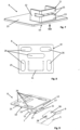
Figur 6 zeigt einen detaillierten Aufbau der Sensoreinheit 4, wie sie in den Ausführungsformen entsprechend denFiguren 1 bis 5 verwendet wird. Die Trägerstruktur 5 der Sensoreinheit 4 ist ein im Wesentlichen plattenförmiges Element mit einem zentralen Bereich 22, der das Sensorelement 6, beispielsweise ein solches mit drei einzelnen Sensorzellen 23, aufnimmt. Außerdem sind alle Anschlüsse des Sensorelements 6 zu einem Anschlussbereich 24 geführt. Alle Anschlüsse können über diesen Anschlussbereich 24 oder direkt zu einer nicht näher gezeigten Steckverbindung, bevorzugt am Rand der Trägerstruktur 5, geführt sein, so dass dann, wenn die Sensoreinheit 4 an den Verankerungsteilen 8 befestigt wird, beispielsweise indem sie in die Endabschnitte 12 der Anschlussteile 11 eingeschoben wird, gleichzeitig eine elektrische Verbindung mit einer Auswerteeinheit der Sitzbelegungserkennung erhalten wird. - Die Verbindungselemente 9, wie sie an der Trägerstruktur 5 der Sensoreinheit 4 vorgesehen sind, können strukturiert werden, beispielsweise mit Vorsprüngen und Hinterschneidungen, so dass entsprechend strukturierte Bereiche des jeweiligen Anschlussteils 11 in entsprechend strukturierte Bereiche des Verbindungselements 9 eingreifen und sich gegebenenfalls mit dem Verbindungselement 9 zusätzlich verrasten oder sich verhaken.
- In den
Figuren 7 bis 9 sind verschiedene Verankerungsteile 8 gezeigt, wie sie in den Ausführungsformen derFiguren 1 bis 5 eingesetzt werden können. - Das Verankerungsteil 8 der
Figur 7 und dasjenige derFigur 9 ist mit demjenigen vergleichbar, das in der Ausführungsform derFigur 2 schematisch im Querschnitt dargestellt ist. Das Basisteil 10, auch als Grundplatte 25 bezeichnet, stellt eine gute Verankerung in dem Schaum des Schaumpolsters 1 sicher. Von dem Basisteil 10 erstrecken sich, etwa senkrecht zu deren Flächenebene, die Stege 13, die sich in Arme 15 des Abschnitts fortsetzen, der das Anschlussteil 11 des Verankerungsteils 8 bildet. Die Enden bzw. Kanten der beiden Arme 15 liegen so gegenüber, dass ein Spalt oder eine Nut vorhanden ist, in die sich dann das Verbindungselement 9 der Trägerstruktur 5 einfügt. Der eine Arm 15 des Anschlussteils 11 ist geringfügig derart federnd ausgeführt, dass sich beim Einfügen des Verbindungselements 9 die Öffnungsweite der Nut vergrößert und entsprechend das Verbindungselement 9 zwischen den Armen 15 eingeklemmt wird, um die Sensoreinheit 4 an den Verankerungsteil 8 sicher zu befestigen. - Die
Figur 8 zeigt eine Draufsicht auf ein Verankerungsteil 8 entsprechend demjenigen, das inFigur 7 gezeigt ist, aus Richtung des Sichtpfeils VIII inFigur 7 . In der Grundplatte 25 bzw. dem Basisteil 10 sind mehrere Schlitze 26 vorhanden, die eine Art Verankerungsöffnungen bilden, in die der Schaum des Schaumpolsters 1 eindringen kann und so das Basisteil 10 zusätzlich verankert. - Die
Figur 9 zeigt ein Verankerungsteil 8 in einer perspektivischen Darstellung entsprechend demjenigen, das in denFiguren 7 und 8 dargestellt ist, aus Richtung des Sichtpfeils VIII inFigur 7 , wobei inFigur 9 zusätzlich ein der Befestigungseinrichtung 7 zugeordnetes, angepasstes Verbindungselement 9 der Trägerstruktur 5 gezeigt ist. DieFigur 9 zeigt jedoch in der Grundplatte 25 bzw. dem Basisteil 10 mehrere Schlitze 26, die auch in dem Verankerungsteil 8 derFigur 8 gezeigt sind, jedoch nicht in derFigur 7 . Verglichen mit der Ausführungsform, wie sie inFigur 7 dargestellt ist, besitzt der eine Arm 15 der Ausführungsform derFigur 9 , der sich weiter entfernt von dem Basisteil 10 befindet, an seiner freien Kante zwei Vorsprünge 27. Wenn das Verbindungselement 9 der Trägerstruktur 5 in das Anschlussteil 11 des Verankerungsteils 8 eingesetzt bzw. eingeschoben ist, greifen die zwei Vorsprünge 27 in korrespondierende Ausnehmungen oder Durchgangslöcher 28 in dem Verbindungselement 9 ein und verriegeln auf diese Weise das Verbindungselement 9 zusätzlich an dem Anschlussteil 11. DieFigur 9 zeigt darüber hinaus einen Teilausschnitt des Verbindungselements 9 der Trägerstruktur 5 entsprechend demjenigen, das inFigur 6 gezeigt ist. Die Form und die Anzahl der Durchgangslöcher 28 und der dazu korrespondierenden Vorsprünge 27 sind nicht auf diejenigen beschränkt, die inFigur 9 dargestellt sind.
Claims (10)
- Fahrzeugsitz mit einer Sensoreinheit zur Sitzbelegungserkennung, die auf der der Sitzseite eines Schaumpolsters (1) abgewandten Unterseite (3) angeordnet ist und bei Belastung des Schaumpolsters (1) an diesem zumindest teilweise anliegt, wobei die Sensoreinheit (4) eine Trägerstruktur (5) umfasst, an oder auf der mindestens ein Sensorelement (6) angeordnet ist, wobei die Sensoreinheit (4) über mindestens eine Befestigungseinrichtung (7), die mindestens ein dem Schaumpolster (1) zugeordnetes, einstückiges Verankerungsteil (8) aufweist, das ein in dem Schaumpolster (1) integriertes Basisteil (10) und mindestens ein von dem Schaumpolster (1) vorstehendes Anschlussteil (11) aufweist und mindestens ein der Trägerstruktur (5) zugeordnetes Verbindungselement (9) aufweist, an dem Schaumpolster (1) angeordnet ist, wobei eine jeweilige Verbindung zwischen dem Anschlussteil (11) des Verankerungsteils (8) und dem Verbindungselement (9) der Trägerstruktur (5) eine über eine Nut-Feder-Verbindung kraft- und/oder formschlüssig ineinandergreifende Verbindung ist, dadurch gekennzeichnet, dass sich ein Arm (15) an dem Anschlussteil (11) der Befestigungseinrichtung (7) fortsetzt und der Arm (15) an seiner freien Kante mindestens einen Vorsprung (27) aufweist, der in eine korrespondierende Ausnehmung oder ein korrespondierendes Durchgangsloch (28) in dem Verbindungselement (9) eingreift und das Verbindungselement (9) zusätzlich an dem Anschlussteil (11) einrastend verriegelt.
- Fahrzeugsitz nach Anspruch 1, dadurch gekennzeichnet, dass die Sensoreinheit (4) über mindestens zwei Befestigungseinrichtungen (7) gehalten ist, die die Trägerstruktur (5) an gegenüberliegenden Seiten halten.
- Fahrzeugsitz nach einem der Ansprüche 1 bis 2, dadurch gekennzeichnet, dass die Sensoreinheit (4) in einer Ausnehmung (19) des Schaumpolsters (1), die eine Bodenfläche (20) und Seitenwände (21) aufweist, angeordnet ist.
- Fahrzeugsitz nach Anspruch 3, dadurch gekennzeichnet, dass das Anschlussteil (11) des Verankerungsteils (8) von einer Seitenwand (21) der Ausnehmung (19) vorsteht.
- Fahrzeugsitz nach einem der Ansprüche 1 bis 3, dadurch gekennzeichnet, dass das Anschlussteil (11) des Verankerungsteils (8) von der Unterseite (3) des Schaumpolsters (1) vorsteht.
- Fahrzeugsitz nach Anspruch 2, dadurch gekennzeichnet, dass das Verbindungselement (9) ein flügelartiges Flächenelement (9) ist.
- Fahrzeugsitz nach einem der Ansprüche 1 bis 6, dadurch gekennzeichnet, dass das Basisteil (10) in das Schaumpolster (1) eingeschäumt ist.
- Fahrzeugsitz nach einem der Ansprüche 1 bis 6, dadurch gekennzeichnet, dass das Basisteil (10) in einen Einschnitt des Schaumpolsters (1) eingesteckt ist.
- Fahrzeugsitz nach einem der Ansprüche 1 bis 8, dadurch gekennzeichnet, dass das Basisteil (10) zumindest teilweise als Platte (25) mit Öffnungen (26) ausgeführt ist.
- Fahrzeugsitz nach einem der Ansprüche 1 bis 9, dadurch gekennzeichnet, dass das Basisteil (10) einen Federarm-Abschnitt (17) aufweist.
Applications Claiming Priority (1)
| Application Number | Priority Date | Filing Date | Title |
|---|---|---|---|
| DE202018001736.1U DE202018001736U1 (de) | 2018-04-03 | 2018-04-03 | Fahrzeugsitz mit einer Sensoreinheit zur Sitzbelegungserkennung |
Publications (2)
| Publication Number | Publication Date |
|---|---|
| EP3549818A1 EP3549818A1 (de) | 2019-10-09 |
| EP3549818B1 true EP3549818B1 (de) | 2023-08-02 |
Family
ID=65729046
Family Applications (1)
| Application Number | Title | Priority Date | Filing Date |
|---|---|---|---|
| EP19000119.8A Active EP3549818B1 (de) | 2018-04-03 | 2019-03-07 | Fahrzeugsitz mit einer sensoreinheit zur sitzbelegungserkennung |
Country Status (2)
| Country | Link |
|---|---|
| EP (1) | EP3549818B1 (de) |
| DE (1) | DE202018001736U1 (de) |
Families Citing this family (1)
| Publication number | Priority date | Publication date | Assignee | Title |
|---|---|---|---|---|
| DE202019003941U1 (de) * | 2019-09-20 | 2020-12-23 | Scherdel Marienberg Gmbh | Sitzbelegungssensoreinheit |
Citations (1)
| Publication number | Priority date | Publication date | Assignee | Title |
|---|---|---|---|---|
| WO2019149602A1 (de) * | 2018-01-30 | 2019-08-08 | Audi Ag | Schaumteil eines kraftfahrzeugsitzes mit sitzbelegungserkennung sowie verfahren zur herstellung eines solchen |
Family Cites Families (8)
| Publication number | Priority date | Publication date | Assignee | Title |
|---|---|---|---|---|
| JP3728711B2 (ja) | 1996-11-29 | 2005-12-21 | アイシン精機株式会社 | 着座検出装置 |
| FR2853057B1 (fr) * | 2003-03-26 | 2005-09-23 | Cera | Dispositif de detection d'enfoncement a amplificateur de detection |
| DE102008005399A1 (de) | 2008-01-21 | 2009-07-30 | Proseat Gmbh & Co. Kg | Funktionseinleger beispielsweise für Sitze |
| DE202011005145U1 (de) * | 2011-02-24 | 2012-06-29 | I.G. Bauerhin Gmbh | Belegungserfassungseinrichtung zum Detektieren des Belegungszustandes eines Kraftfahrzeugsitzes |
| DE202013009078U1 (de) | 2013-10-14 | 2015-01-16 | I.G. Bauerhin Gmbh | Drucksensor-Einheit zum Detektieren des Belegungszustands eines Kraftfahrzeugsitzes |
| JP6405456B2 (ja) * | 2015-04-20 | 2018-10-17 | 株式会社フジクラ | 荷重検出装置 |
| FR3056476B1 (fr) * | 2016-09-23 | 2019-08-30 | Faurecia Sieges D'automobile | Element de siege et siege comportant un tel element de siege |
| DE202017005093U1 (de) | 2016-10-13 | 2017-12-06 | Scherdel Marienberg Gmbh | Vorrichtung zur Erfassung einer Sitzbelegung an einem Kraftfahrzeugsitz |
-
2018
- 2018-04-03 DE DE202018001736.1U patent/DE202018001736U1/de active Active
-
2019
- 2019-03-07 EP EP19000119.8A patent/EP3549818B1/de active Active
Patent Citations (1)
| Publication number | Priority date | Publication date | Assignee | Title |
|---|---|---|---|---|
| WO2019149602A1 (de) * | 2018-01-30 | 2019-08-08 | Audi Ag | Schaumteil eines kraftfahrzeugsitzes mit sitzbelegungserkennung sowie verfahren zur herstellung eines solchen |
Also Published As
| Publication number | Publication date |
|---|---|
| EP3549818A1 (de) | 2019-10-09 |
| DE202018001736U1 (de) | 2019-07-31 |
Similar Documents
| Publication | Publication Date | Title |
|---|---|---|
| DE10100805C2 (de) | Fahrzeugsitzaufbau | |
| DE112013002367B4 (de) | Auf Druck reagierende Sitzbelegungssensoreinheit und Autositz | |
| DE112007000890B4 (de) | System, umfassend eine Kraftfahrzeugsitzgleitschiene und einen Körper, der dazu bestimmt ist, daran befestigt zu werden und Herstellungsverfahren | |
| DE102008006367B4 (de) | Fahrzeugsitz | |
| DE112011100271T5 (de) | Vorrichtung für eine Sitzbaugruppe mit Querträger | |
| DE102004031143A1 (de) | Federsensoranordnung für ein Fahrzeugsitzpolster | |
| DE202014103406U1 (de) | Fahrzeugfussbodenmattensystem | |
| WO2011029491A1 (de) | Drucksensor-einheit | |
| DE102010002525B4 (de) | Sitzbaugruppe mit einer beweglichen Kopfstützen-Baugruppe | |
| EP1093426A1 (de) | Vorrichtung zur überwachung der verriegelungsstellung einer verbindungseinrichtung zur befestigung eines kindersitzes | |
| DE102020133018B4 (de) | Ankerbefestigungserkennungssensoren | |
| EP2450228A2 (de) | Fahrzeugsitz | |
| DE102022109336A1 (de) | Verkleidung eines Elements eines Fahrzeugsitzes, mit einer Vibrationsvorrichtung | |
| DE102021123374A1 (de) | Hängende Auflage für einen Fahrzeugsitz mit Führungshalterung der elektrischen Kabel | |
| DE102004031144A1 (de) | Federsensor-Rückhalteanordnung für eine in einem Fahrzeugsitzpolster angebrachte Sensoreinrichtung | |
| EP3549818B1 (de) | Fahrzeugsitz mit einer sensoreinheit zur sitzbelegungserkennung | |
| DE102017208726B4 (de) | Sitzlängsverstellvorrichtung | |
| DE2739999A1 (de) | Fahrzeugsitz | |
| DE102019114909B4 (de) | Fahrzeugsitz mit einer Abdeckung zur Auskleidung einer Durchgangsöffnung in einem Polsterteil des Fahrzeugsitzes, sowie Verfahren zur Montage einer Abdeckung an ein Sitzteil eines Fahrzeugsitzes | |
| DE102018002741B4 (de) | Fahrzeugsitz mit einer Sensoreinheit zur Sitzbelegungserkennung | |
| DE102023207641A1 (de) | Bezugsmaterialbefestigung | |
| DE102017200946A1 (de) | Befestigungsvorrichtung zur Befestigung eines Sitzbezugs | |
| DE19510603A1 (de) | Aufrollautomat für einen Sicherheitsgurt | |
| DE202015001912U1 (de) | Sitzbelegungssensoreinheit und Sitz | |
| DE19955294C2 (de) | Kraftfahrzeugsitz mit Sitztiefenverstellung |
Legal Events
| Date | Code | Title | Description |
|---|---|---|---|
| PUAI | Public reference made under article 153(3) epc to a published international application that has entered the european phase |
Free format text: ORIGINAL CODE: 0009012 |
|
| STAA | Information on the status of an ep patent application or granted ep patent |
Free format text: STATUS: THE APPLICATION HAS BEEN PUBLISHED |
|
| AK | Designated contracting states |
Kind code of ref document: A1 Designated state(s): AL AT BE BG CH CY CZ DE DK EE ES FI FR GB GR HR HU IE IS IT LI LT LU LV MC MK MT NL NO PL PT RO RS SE SI SK SM TR |
|
| AX | Request for extension of the european patent |
Extension state: BA ME |
|
| STAA | Information on the status of an ep patent application or granted ep patent |
Free format text: STATUS: REQUEST FOR EXAMINATION WAS MADE |
|
| 17P | Request for examination filed |
Effective date: 20200310 |
|
| RBV | Designated contracting states (corrected) |
Designated state(s): AL AT BE BG CH CY CZ DE DK EE ES FI FR GB GR HR HU IE IS IT LI LT LU LV MC MK MT NL NO PL PT RO RS SE SI SK SM TR |
|
| STAA | Information on the status of an ep patent application or granted ep patent |
Free format text: STATUS: EXAMINATION IS IN PROGRESS |
|
| 17Q | First examination report despatched |
Effective date: 20210224 |
|
| GRAP | Despatch of communication of intention to grant a patent |
Free format text: ORIGINAL CODE: EPIDOSNIGR1 |
|
| STAA | Information on the status of an ep patent application or granted ep patent |
Free format text: STATUS: GRANT OF PATENT IS INTENDED |
|
| INTG | Intention to grant announced |
Effective date: 20230322 |
|
| GRAS | Grant fee paid |
Free format text: ORIGINAL CODE: EPIDOSNIGR3 |
|
| GRAA | (expected) grant |
Free format text: ORIGINAL CODE: 0009210 |
|
| STAA | Information on the status of an ep patent application or granted ep patent |
Free format text: STATUS: THE PATENT HAS BEEN GRANTED |
|
| AK | Designated contracting states |
Kind code of ref document: B1 Designated state(s): AL AT BE BG CH CY CZ DE DK EE ES FI FR GB GR HR HU IE IS IT LI LT LU LV MC MK MT NL NO PL PT RO RS SE SI SK SM TR |
|
| REG | Reference to a national code |
Ref country code: GB Ref legal event code: FG4D Free format text: NOT ENGLISH |
|
| REG | Reference to a national code |
Ref country code: CH Ref legal event code: EP |
|
| REG | Reference to a national code |
Ref country code: DE Ref legal event code: R096 Ref document number: 502019008710 Country of ref document: DE |
|
| REG | Reference to a national code |
Ref country code: IE Ref legal event code: FG4D Free format text: LANGUAGE OF EP DOCUMENT: GERMAN |
|
| REG | Reference to a national code |
Ref country code: SE Ref legal event code: TRGR |
|
| REG | Reference to a national code |
Ref country code: LT Ref legal event code: MG9D |
|
| REG | Reference to a national code |
Ref country code: NL Ref legal event code: MP Effective date: 20230802 |
|
| PG25 | Lapsed in a contracting state [announced via postgrant information from national office to epo] |
Ref country code: GR Free format text: LAPSE BECAUSE OF FAILURE TO SUBMIT A TRANSLATION OF THE DESCRIPTION OR TO PAY THE FEE WITHIN THE PRESCRIBED TIME-LIMIT Effective date: 20231103 |
|
| PG25 | Lapsed in a contracting state [announced via postgrant information from national office to epo] |
Ref country code: IS Free format text: LAPSE BECAUSE OF FAILURE TO SUBMIT A TRANSLATION OF THE DESCRIPTION OR TO PAY THE FEE WITHIN THE PRESCRIBED TIME-LIMIT Effective date: 20231202 |
|
| PG25 | Lapsed in a contracting state [announced via postgrant information from national office to epo] |
Ref country code: RS Free format text: LAPSE BECAUSE OF FAILURE TO SUBMIT A TRANSLATION OF THE DESCRIPTION OR TO PAY THE FEE WITHIN THE PRESCRIBED TIME-LIMIT Effective date: 20230802 Ref country code: PT Free format text: LAPSE BECAUSE OF FAILURE TO SUBMIT A TRANSLATION OF THE DESCRIPTION OR TO PAY THE FEE WITHIN THE PRESCRIBED TIME-LIMIT Effective date: 20231204 Ref country code: NO Free format text: LAPSE BECAUSE OF FAILURE TO SUBMIT A TRANSLATION OF THE DESCRIPTION OR TO PAY THE FEE WITHIN THE PRESCRIBED TIME-LIMIT Effective date: 20231102 Ref country code: NL Free format text: LAPSE BECAUSE OF FAILURE TO SUBMIT A TRANSLATION OF THE DESCRIPTION OR TO PAY THE FEE WITHIN THE PRESCRIBED TIME-LIMIT Effective date: 20230802 Ref country code: LV Free format text: LAPSE BECAUSE OF FAILURE TO SUBMIT A TRANSLATION OF THE DESCRIPTION OR TO PAY THE FEE WITHIN THE PRESCRIBED TIME-LIMIT Effective date: 20230802 Ref country code: LT Free format text: LAPSE BECAUSE OF FAILURE TO SUBMIT A TRANSLATION OF THE DESCRIPTION OR TO PAY THE FEE WITHIN THE PRESCRIBED TIME-LIMIT Effective date: 20230802 Ref country code: IS Free format text: LAPSE BECAUSE OF FAILURE TO SUBMIT A TRANSLATION OF THE DESCRIPTION OR TO PAY THE FEE WITHIN THE PRESCRIBED TIME-LIMIT Effective date: 20231202 Ref country code: HR Free format text: LAPSE BECAUSE OF FAILURE TO SUBMIT A TRANSLATION OF THE DESCRIPTION OR TO PAY THE FEE WITHIN THE PRESCRIBED TIME-LIMIT Effective date: 20230802 Ref country code: GR Free format text: LAPSE BECAUSE OF FAILURE TO SUBMIT A TRANSLATION OF THE DESCRIPTION OR TO PAY THE FEE WITHIN THE PRESCRIBED TIME-LIMIT Effective date: 20231103 Ref country code: FI Free format text: LAPSE BECAUSE OF FAILURE TO SUBMIT A TRANSLATION OF THE DESCRIPTION OR TO PAY THE FEE WITHIN THE PRESCRIBED TIME-LIMIT Effective date: 20230802 |
|
| PG25 | Lapsed in a contracting state [announced via postgrant information from national office to epo] |
Ref country code: PL Free format text: LAPSE BECAUSE OF FAILURE TO SUBMIT A TRANSLATION OF THE DESCRIPTION OR TO PAY THE FEE WITHIN THE PRESCRIBED TIME-LIMIT Effective date: 20230802 |
|
| PG25 | Lapsed in a contracting state [announced via postgrant information from national office to epo] |
Ref country code: ES Free format text: LAPSE BECAUSE OF FAILURE TO SUBMIT A TRANSLATION OF THE DESCRIPTION OR TO PAY THE FEE WITHIN THE PRESCRIBED TIME-LIMIT Effective date: 20230802 |
|
| PG25 | Lapsed in a contracting state [announced via postgrant information from national office to epo] |
Ref country code: SM Free format text: LAPSE BECAUSE OF FAILURE TO SUBMIT A TRANSLATION OF THE DESCRIPTION OR TO PAY THE FEE WITHIN THE PRESCRIBED TIME-LIMIT Effective date: 20230802 Ref country code: RO Free format text: LAPSE BECAUSE OF FAILURE TO SUBMIT A TRANSLATION OF THE DESCRIPTION OR TO PAY THE FEE WITHIN THE PRESCRIBED TIME-LIMIT Effective date: 20230802 Ref country code: ES Free format text: LAPSE BECAUSE OF FAILURE TO SUBMIT A TRANSLATION OF THE DESCRIPTION OR TO PAY THE FEE WITHIN THE PRESCRIBED TIME-LIMIT Effective date: 20230802 Ref country code: EE Free format text: LAPSE BECAUSE OF FAILURE TO SUBMIT A TRANSLATION OF THE DESCRIPTION OR TO PAY THE FEE WITHIN THE PRESCRIBED TIME-LIMIT Effective date: 20230802 Ref country code: DK Free format text: LAPSE BECAUSE OF FAILURE TO SUBMIT A TRANSLATION OF THE DESCRIPTION OR TO PAY THE FEE WITHIN THE PRESCRIBED TIME-LIMIT Effective date: 20230802 Ref country code: SK Free format text: LAPSE BECAUSE OF FAILURE TO SUBMIT A TRANSLATION OF THE DESCRIPTION OR TO PAY THE FEE WITHIN THE PRESCRIBED TIME-LIMIT Effective date: 20230802 |
|
| REG | Reference to a national code |
Ref country code: DE Ref legal event code: R097 Ref document number: 502019008710 Country of ref document: DE |
|
| PLBE | No opposition filed within time limit |
Free format text: ORIGINAL CODE: 0009261 |
|
| STAA | Information on the status of an ep patent application or granted ep patent |
Free format text: STATUS: NO OPPOSITION FILED WITHIN TIME LIMIT |
|
| 26N | No opposition filed |
Effective date: 20240503 |
|
| PG25 | Lapsed in a contracting state [announced via postgrant information from national office to epo] |
Ref country code: SI Free format text: LAPSE BECAUSE OF FAILURE TO SUBMIT A TRANSLATION OF THE DESCRIPTION OR TO PAY THE FEE WITHIN THE PRESCRIBED TIME-LIMIT Effective date: 20230802 |
|
| REG | Reference to a national code |
Ref country code: DE Ref legal event code: R119 Ref document number: 502019008710 Country of ref document: DE |
|
| REG | Reference to a national code |
Ref country code: CH Ref legal event code: PL |
|
| PG25 | Lapsed in a contracting state [announced via postgrant information from national office to epo] |
Ref country code: BG Free format text: LAPSE BECAUSE OF FAILURE TO SUBMIT A TRANSLATION OF THE DESCRIPTION OR TO PAY THE FEE WITHIN THE PRESCRIBED TIME-LIMIT Effective date: 20230802 |
|
| PG25 | Lapsed in a contracting state [announced via postgrant information from national office to epo] |
Ref country code: LU Free format text: LAPSE BECAUSE OF NON-PAYMENT OF DUE FEES Effective date: 20240307 |
|
| PG25 | Lapsed in a contracting state [announced via postgrant information from national office to epo] |
Ref country code: MC Free format text: LAPSE BECAUSE OF FAILURE TO SUBMIT A TRANSLATION OF THE DESCRIPTION OR TO PAY THE FEE WITHIN THE PRESCRIBED TIME-LIMIT Effective date: 20230802 |
|
| GBPC | Gb: european patent ceased through non-payment of renewal fee |
Effective date: 20240307 |
|
| PG25 | Lapsed in a contracting state [announced via postgrant information from national office to epo] |
Ref country code: MC Free format text: LAPSE BECAUSE OF FAILURE TO SUBMIT A TRANSLATION OF THE DESCRIPTION OR TO PAY THE FEE WITHIN THE PRESCRIBED TIME-LIMIT Effective date: 20230802 Ref country code: LU Free format text: LAPSE BECAUSE OF NON-PAYMENT OF DUE FEES Effective date: 20240307 Ref country code: BG Free format text: LAPSE BECAUSE OF FAILURE TO SUBMIT A TRANSLATION OF THE DESCRIPTION OR TO PAY THE FEE WITHIN THE PRESCRIBED TIME-LIMIT Effective date: 20230802 |
|
| REG | Reference to a national code |
Ref country code: BE Ref legal event code: MM Effective date: 20240331 |
|
| PG25 | Lapsed in a contracting state [announced via postgrant information from national office to epo] |
Ref country code: DE Free format text: LAPSE BECAUSE OF NON-PAYMENT OF DUE FEES Effective date: 20241001 |
|
| PG25 | Lapsed in a contracting state [announced via postgrant information from national office to epo] |
Ref country code: BE Free format text: LAPSE BECAUSE OF NON-PAYMENT OF DUE FEES Effective date: 20240331 |
|
| PG25 | Lapsed in a contracting state [announced via postgrant information from national office to epo] |
Ref country code: GB Free format text: LAPSE BECAUSE OF NON-PAYMENT OF DUE FEES Effective date: 20240307 |
|
| PG25 | Lapsed in a contracting state [announced via postgrant information from national office to epo] |
Ref country code: IE Free format text: LAPSE BECAUSE OF NON-PAYMENT OF DUE FEES Effective date: 20240307 |
|
| PG25 | Lapsed in a contracting state [announced via postgrant information from national office to epo] |
Ref country code: IE Free format text: LAPSE BECAUSE OF NON-PAYMENT OF DUE FEES Effective date: 20240307 Ref country code: GB Free format text: LAPSE BECAUSE OF NON-PAYMENT OF DUE FEES Effective date: 20240307 Ref country code: DE Free format text: LAPSE BECAUSE OF NON-PAYMENT OF DUE FEES Effective date: 20241001 Ref country code: BE Free format text: LAPSE BECAUSE OF NON-PAYMENT OF DUE FEES Effective date: 20240331 Ref country code: CH Free format text: LAPSE BECAUSE OF NON-PAYMENT OF DUE FEES Effective date: 20240331 |
|
| REG | Reference to a national code |
Ref country code: AT Ref legal event code: MM01 Ref document number: 1594328 Country of ref document: AT Kind code of ref document: T Effective date: 20240307 |
|
| PG25 | Lapsed in a contracting state [announced via postgrant information from national office to epo] |
Ref country code: AT Free format text: LAPSE BECAUSE OF NON-PAYMENT OF DUE FEES Effective date: 20240307 |
|
| PG25 | Lapsed in a contracting state [announced via postgrant information from national office to epo] |
Ref country code: CY Free format text: LAPSE BECAUSE OF FAILURE TO SUBMIT A TRANSLATION OF THE DESCRIPTION OR TO PAY THE FEE WITHIN THE PRESCRIBED TIME-LIMIT; INVALID AB INITIO Effective date: 20190307 |
|
| PG25 | Lapsed in a contracting state [announced via postgrant information from national office to epo] |
Ref country code: HU Free format text: LAPSE BECAUSE OF FAILURE TO SUBMIT A TRANSLATION OF THE DESCRIPTION OR TO PAY THE FEE WITHIN THE PRESCRIBED TIME-LIMIT; INVALID AB INITIO Effective date: 20190307 |
|
| PG25 | Lapsed in a contracting state [announced via postgrant information from national office to epo] |
Ref country code: TR Free format text: LAPSE BECAUSE OF FAILURE TO SUBMIT A TRANSLATION OF THE DESCRIPTION OR TO PAY THE FEE WITHIN THE PRESCRIBED TIME-LIMIT Effective date: 20230802 |
|
| PGFP | Annual fee paid to national office [announced via postgrant information from national office to epo] |
Ref country code: SE Payment date: 20260323 Year of fee payment: 8 |
|
| PGFP | Annual fee paid to national office [announced via postgrant information from national office to epo] |
Ref country code: IT Payment date: 20260320 Year of fee payment: 8 |
|
| PGFP | Annual fee paid to national office [announced via postgrant information from national office to epo] |
Ref country code: FR Payment date: 20260323 Year of fee payment: 8 |
|
| PGFP | Annual fee paid to national office [announced via postgrant information from national office to epo] |
Ref country code: CZ Payment date: 20260226 Year of fee payment: 8 |