EP3547864B1 - Schutzhelm, insbesondere motorradhelm, mit schwenkbarem und abnehmbarem kinnteil - Google Patents
Schutzhelm, insbesondere motorradhelm, mit schwenkbarem und abnehmbarem kinnteil Download PDFInfo
- Publication number
- EP3547864B1 EP3547864B1 EP17784642.5A EP17784642A EP3547864B1 EP 3547864 B1 EP3547864 B1 EP 3547864B1 EP 17784642 A EP17784642 A EP 17784642A EP 3547864 B1 EP3547864 B1 EP 3547864B1
- Authority
- EP
- European Patent Office
- Prior art keywords
- helmet
- coupling element
- coupling
- protective helmet
- chin
- Prior art date
- Legal status (The legal status is an assumption and is not a legal conclusion. Google has not performed a legal analysis and makes no representation as to the accuracy of the status listed.)
- Active
Links
Images



Classifications
-
- A—HUMAN NECESSITIES
- A42—HEADWEAR
- A42B—HATS; HEAD COVERINGS
- A42B3/00—Helmets; Helmet covers ; Other protective head coverings
- A42B3/32—Collapsible helmets; Helmets made of separable parts ; Helmets with movable parts, e.g. adjustable
- A42B3/326—Helmets with movable or separable chin or jaw guard
-
- A—HUMAN NECESSITIES
- A42—HEADWEAR
- A42B—HATS; HEAD COVERINGS
- A42B3/00—Helmets; Helmet covers ; Other protective head coverings
- A42B3/04—Parts, details or accessories of helmets
- A42B3/08—Chin straps or similar retention devices
-
- A—HUMAN NECESSITIES
- A42—HEADWEAR
- A42B—HATS; HEAD COVERINGS
- A42B3/00—Helmets; Helmet covers ; Other protective head coverings
- A42B3/04—Parts, details or accessories of helmets
- A42B3/06—Impact-absorbing shells, e.g. of crash helmets
-
- A—HUMAN NECESSITIES
- A42—HEADWEAR
- A42B—HATS; HEAD COVERINGS
- A42B3/00—Helmets; Helmet covers ; Other protective head coverings
- A42B3/32—Collapsible helmets; Helmets made of separable parts ; Helmets with movable parts, e.g. adjustable
- A42B3/324—Adjustable helmets
Definitions
- the protective helmet can e.g. a motorcycle helmet, in particular with a chin part that can be repeatedly swiveled and removed repeatedly.
- the chin part can preferably be removed without tools.
- the purpose of the protective helmet is not limited to motorcycles, but also extends to other man-driven land, air and water vehicles, such as. B. open racing cars, snowmobiles, gliders, racing boats, hang gliders, etc.
- Full-face helmets have a fixed chin section and preferably a completely lockable visor.
- Half-shell helmets also called open face helmets, do not have a fixed chin section.
- Half-shell helmets must protect the forehead, ears and neck.
- “Flip-up helmets” are a variation of the full-face helmet in which the chin can be folded up.
- Multi-helmets are helmets that can be modified, usually with the ability to remove the chin section, so that they can be used either as a full face helmet or a jet helmet.
- Multi helmets with repeatedly removable chin parts can have the chin part from a lower one at chin height Remove the integral helmet position so that a jet helmet or a 3/4 helmet is created.
- the chin part in addition to being detachable, can also be pivotable, as in the case of the "flip-up helmets”.
- the pamphlet DE 44 17 658 A1 describes a protective helmet for motorcyclists which has a helmet shell and a chin guard that can be pivoted with respect to the helmet shell.
- the visor and the chin guard should be locked against each other in such a way that the chin guard can only be swiveled into the dismantling position when the visor is removed. This is achieved by a dome-proof stop that limits the opening area of the helmet visor and the swivel range of the chin bar.
- the chin guard can only be swiveled into the dismantling position after the visor has been removed.
- the pamphlet DE 10 2014 218 041 A1 describes a motorcycle helmet with a jet helmet part and a repeatedly pivotable and repeatedly removable chin part.
- the chin part is detachably connected to the jet helmet part by a coupling part.
- the coupling part For assembly, the chin part is pushed onto the open face helmet part 1 in a coupling direction, the coupling part closing automatically and either being automatically locked or having to be locked by the user.
- the coupling part can only be actuated in a defined position or position and can be mechanically blocked in all other positions by the coupling gear.
- the protective helmet described here has, according to at least one embodiment, a jet helmet part and a chin part, which are releasably connected to one another via a coupling part.
- the jet helmet part can be designed not only in the classic jet helmet shape, but also smaller in the form of a half-shell helmet or larger in the manner of a 3/4 helmet with protective parts for the cheek and jaw area pulled further down and forwards.
- the chin part can then be formed with shorter or longer bars in the cheek and jaw area and can therefore only be present in the chin area in the minimum extreme case and up to the ear area in the maximum extreme case.
- the chin part and the jet helmet part can be pivoted relative to one another in pivoting directions between a full-face helmet position and a jet helmet position by means of a pivoting mechanism.
- the chin part can e.g. At least between a front lower full-face helmet position in an upper and / or rear open face helmet position that is swiveled upwards by between approx. 90 ° to approx. 180 ° and can be locked in these extreme positions, but also in intermediate or over-extreme positions.
- the coupling part has a first coupling element which is attached to the chin part, and a second coupling element which is attached to the jet helmet part.
- the coupling elements are designed to interlock for mutual releasable positive coupling.
- the coupling elements are preferably designed in such a way that they automatically lock into one another in a form-fitting manner during coupling and for one Decoupling require a separate and thus deliberate actuation by a user
- the protective helmet and / or the coupling part are designed such that a locking mechanism is actuated by the pivoting mechanism.
- the locking mechanism can in particular be designed in such a way that it is automatically actuated by the pivoting mechanism.
- the locking mechanism preferably comprises a blocking slide and is preferably set up so that the blocking slide blocks the first coupling element in the integral helmet position in such a way that decoupling of the coupling elements is blocked. In the open face helmet position, the blocking of the first coupling element is preferably released, so that decoupling of the coupling elements is made possible.
- the chin part can be detached from the jet helmet part. The loosening can preferably take place without tools.
- the blocking slide can prevent unintentional decoupling of the coupling elements or detachment of the chin part from the jet helmet part in a particularly efficient manner. Because the blocking slide is automatically actuated by the chin part kinematics, no manual locking of the coupling elements is necessary.
- the coupling elements can be designed as latching elements, for example, with the spring action of the latching elements advantageously being able to be made soft due to the locking function by means of the blocking slide.
- the first coupling element is connected to the chin part by means of a swivel arm.
- the pivot arm is preferably moved or pivoted when the chin part is pivoted relative to the jet helmet part.
- the swivel arm has a locking cam through which the blocking slide is swiveled from the open face helmet position into the full face helmet position is shifted such that the first coupling element is blocked.
- the pivot arm is preferably connected to the chin part via a first joint and to the first coupling element via a second joint.
- the second coupling element has a female coupling member and the first coupling element has a male coupling member, wherein the coupling members are designed such that the male coupling member can be locked with the female coupling member.
- the male coupling member can e.g. be designed as a locking lug.
- the female coupling member can e.g. be designed as a locking recess or locking recess.
- a form-fitting connection is preferably produced by latching the coupling members or latching the latching nose and latching recess.
- the coupling part is designed such that a latching of the latching lug with the latching recess can be released by a unhooking movement.
- the blocking slide is preferably designed such that the unhooking movement for releasing the latching in the integral helmet position is blocked by the blocking slide.
- the blocking slide can be arranged behind the locking lug in the direction of the unhooking movement, whereby a decoupling of the latching lug and the latching recess is no longer possible due to the arrangement of the blocking slide behind the locking lug.
- the blocking slide when the chin part is pivoted into the open face helmet position, the blocking slide is automatically displaced in such a way that the unhooking movement for releasing the latching is released or possible.
- the blocking slide can be moved in such a way that it in the open face helmet position is no longer arranged behind the locking lug and thus can no longer block a decoupling of the locking.
- the first coupling element is designed in one piece.
- the first coupling element can consist of an integrally formed plastic part.
- the first coupling element can be a plastic injection-molded part.
- the first coupling element can be designed as a chin part slide which is pivotably connected to the chin part.
- the first coupling element has a guide in which the blocking slide is guided.
- the blocking slide can, in particular, be slidably displaceable within the guide.
- the tour can e.g. have a plurality of guide elements.
- the guide elements can be designed as guide hooks, which are preferably formed in one piece with the first coupling element.
- the first coupling element also has a link guide in which a link pin, which is attached to the chin part, is guided.
- the link pin can be connected to the first coupling element, for example, by a spring element.
- the pivot arm which can be connected to the chin part via a first joint and to the first coupling element via a second joint, and the link pin guided in the link guide, can be used to implement a four-bar kinematics system, through which the first coupling element can be pivoted relative to the chin part his.
- the second coupling element is designed as a slide-in frame.
- the locking recess is preferably formed in the slide-in frame.
- the second The coupling element can be designed as a one-piece plastic part, which is preferably non-rotatably connected to the jet helmet part.
- a coupling part is arranged on the left and right of a face opening of the protective helmet.
- the coupling parts or their coupling elements can be on the two sides of the protective helmet in particular to the longitudinal center axis of the protective helmet, i. H. mirror-inverted in the direction of travel, but otherwise structurally identical.
- identical or identically acting components can each be provided with the same reference symbols.
- the elements shown and their proportions to one another are fundamentally not to be regarded as true to scale. Rather, individual elements for better representability and / or be shown exaggerated thick or large for better understanding.
- the Figure 1 shows a protective helmet 100 for a motorcyclist consisting of a jet helmet part 1 and a bow-shaped chin part 2.
- the chin part 2 is held detachably via a coupling part 3 attached to the side approximately in an ear area of the jet helmet part 1 and can be pivoted up and down in the directions of arrows 4 instead of around a pivot point like a conventional swivel joint.
- the chin part 2 is shown in a lower, folded-down full-face helmet position and can be pivoted upwards through approximately 90 ° into a jet helmet position.
- the protective helmet has a visor 5 made of transparent plastic, which is attached to the jet helmet part 1 so that it can pivot in the directions of the arrow 6, independently of the chin part 2.
- the visor 5 and the chin part 2 are cut in the area of the coupling part 3 and shown with dashed outline edges in order to illustrate their position on the protective helmet.
- the two coupling parts 3 of the helmet allow repeated dismantling and assembly of the chin part 2 with the open face helmet part 1.
- a user pulls the chin part 2 in a decoupling direction 8 from the open face helmet part 1.
- the chin part 2 is pushed onto the jet helmet part 1 in a coupling direction 9.
- the dismantled state of the chin part 2 from the jet helmet part 1 shows Figure 2 , the chin part 2 being pulled off in the decoupling direction 8 after the coupling part 3 was opened by the user.
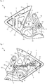
- the Figures 3 to 8 show various schematic representations of a coupling part 3 according to an embodiment. It is in the Figures 3, 4 , 7 and 8 a state of the coupling part 3 is shown, which can occur in particular in the open face helmet position. The Figures 5 and 6 however, show a state of the coupling part 3 as it occurs in particular in the full-face helmet position.
- the coupling part 3 has a first coupling element 10, which is fixed on the chin part 2, and a second coupling element 11, which is fixed on the jet helmet part 1.
- the first coupling element 10 is designed as a one-piece plastic part and has a latching nose 16 which can latch for a releasable positive coupling with a latching recess 17 of the second coupling element 11, which in the embodiment shown is also designed as a one-piece plastic part.
- the coupling part 3 is designed such that a locking mechanism is actuated by the pivoting mechanism by which the chin part 2 is pivoted relative to the jet helmet part 1.
- a blocking slide 7 is displaced in this way by a locking cam 13 of a swivel arm 12, which is connected to the chin part 2 via a first joint 14 and to the first coupling element 10 via a second joint 15 that a decoupling of the coupling elements 10, 11 is blocked.
- the blocking slide 7 is displaced in such a way that an unhooking movement for releasing the latching of the latching lug 16 and the latching recess 17 is blocked by the arrangement of the blocking slide 7, since the blocking slide 7 is arranged behind the latching lug 16 in the direction of the unhooking movement.
- the blocking of the unhooking movement by the blocking slide 7 is in the Figures 5 and 6 shown.
- the first coupling element 10 has a plurality of guide elements 19 which are designed as plastic hooks and through which the blocking slide 7 is displaceably mounted.
- the blocking slide 7 is preferably designed as a one-piece plastic component.
- the first coupling element 10 has a link guide 18 in which a link pin (not shown) is guided, which is attached to the chin part 2.
- the link pin is connected to the first coupling element 10 via a spring (not shown).
- FIGS. 7 and 8 show further perspective views of the coupling part 3 in the open face helmet position, the first coupling element 10 in FIG Figure 8 is decoupled from the second coupling element 11 after the latching lug 16 has been pressed, so that the chin part 2 is released from the jet helmet part 1.
Landscapes
- Helmets And Other Head Coverings (AREA)
Description
- Es wird ein Schutzhelm angegeben. Bei dem Schutzhelm kann es sich z.B. um einen Motorradhelm, insbesondere mit wiederholt schwenkbarem und wiederholt abnehmbarem Kinnteil, handeln. Das Abnehmen des Kinnteils kann vorzugsweise ohne Werkzeug erfolgen. Der Anwendungszweck des Schutzhelms beschränkt sich nicht nur auf Motorräder, sondern erstreckt sich auch auf andere personengelenkte Land-, Luft- und Wasserfahrzeuge, wie z. B. offene Rennkraftfahrzeuge, Schneemobile, Segelflugzeuge, Rennboote, Hängegleiter, etc.
- Grundsätzlich wird bei derartigen Schutzhelmen zwischen Integralhelmen, Jethelmen, Klapphelmen und Multihelmen unterschieden. "Integralhelme" besitzen eine feste Kinnpartie und vorzugsweise ein komplett verschließbares Visier. "Halbschalenhelme", auch Jethelme genannt, verfügen über keine feste Kinnpartie. Es gibt Varianten mit verbautem Visier oder mit Sonnenblende, aber auch Halbschalen mit einem tief gezogenen Visier und etwas weiter nach vorn gezogenen Seiten, die allgemein als 3/4 Helme bezeichnet werden. Halbschalenhelme müssen die Stirn, Ohren und Nacken schützen. "Klapphelme" sind eine Variation des Integralhelms, bei der sich die Kinnpartie hochklappen lässt. Diese sind insbesondere für Brillenträger empfehlenswert und erleichtern das Abnehmen des Helmes nach einem Unfall. Klapphelme mit schwenkbarem Kinnteil können das Kinnteil aus einer in Kinnhöhe befindlichen unteren Integralhelm-Stellung in eine insbesondere um 90° hochgeklappte obere Jethelm-Stellung verschwenken. "Multihelme" sind Helme mit Umbaumöglichkeiten, zumeist der, das Kinnteil abzunehmen, womit sie wahlweise als Integralhelm oder Jethelm genutzt werden können. "Multihelme" mit wiederholt abnehmbarem Kinnteil können das Kinnteil aus einer unteren in Kinnhöhe befindlichen Integralhelm-Stellung entfernen, so dass ein Jethelm oder ein 3/4-Helm entsteht. Bei "Multihelmen" kann das Kinnteil zusätzlich zur Lösbarkeit auch eine Schwenkbarkeit wie bei den "Klapphelmen" aufweisen.
- Die Druckschrift
DE 44 17 658 A1 beschreibt einen Schutzhelm für Motorradfahrer, der eine Helmkalotte und einen gegenüber der Helmkalotte verschwenkbaren Kinnbügel aufweist. Um zu verhindern, dass sich der Kinnbügel ungewollt von der Helmkalotte löst, sollen das Visier und der Kinnbügel so gegeneinander verriegelt werden, dass nur bei abgenommenen Visier der Kinnbügel in die Demontagestellung geschwenkt werden kann. Erreicht wird dies durch einen kalottenfesten Anschlag, der den Öffnungsbereich des Helmvisiers und den Schwenkbereich des Kinnbügels begrenzt. Erst nach Abnehmen des Visiers lässt sich der Kinnbügel in die Demontagestellung schwenken. - In der Druckschrift
DE 10 2014 218 041 A1 ist ein Motorradhelm mit einem Jethelmteil und einem wiederholt schwenkbarem und wiederholt abnehmbarem Kinnteil beschrieben. Das Kinnteil ist dabei durch ein Kopplungsteil mit dem Jethelmteil lösbar verbunden. Zur Montage wird das Kinnteil in einer Kopplungsrichtung auf das Jethelmteil 1 aufgeschoben, wobei sich das Kopplungsteil automatisch schließt sowie entweder automatisch verriegelt oder durch den Nutzer verriegelt werden muss. Beispielsweise kann das Kopplungsteil nur in einer definierten Position oder Stellung betätigbar und in allen übrigen Stellungen durch das Koppelgetriebe mechanisch blockiert sein. - Es ist eine zu lösende Aufgabe zumindest einiger Ausführungsformen, eine alternative, kostengünstige und zuverlässige Lösung für einen Schutzhelm anzugeben, durch welche eine automatische mechanische Blockierung einer Entkopplung zwischen Jethelmteil und Kinnteil eines Schutzhelms erreicht wird.
- Diese Aufgabe wird durch einen Gegenstand gemäß dem unabhängigen Patentanspruch gelöst. Vorteilhafte Ausführungsformen und Weiterbildungen des Gegenstandes gehen weiterhin aus den abhängigen Patentansprüchen, der nachfolgenden Beschreibung und aus den Zeichnungen hervor.
- Der hier beschriebene Schutzhelm weist gemäß zumindest einer Ausführungsform ein Jethelmteil und ein Kinnteil auf, welche über ein Kopplungsteil lösbar miteinander verbunden sind. Das Jethelmteil kann nicht nur in klassischer Jethelm-Form, sondern auch kleiner in der Art der Form eines Halbschalenhelms oder größer in Art eines 3/4-Helms mit weiter nach unten und vorn gezogenen Schutzteilen für den Wangen- und Kieferbereich ausgeführt sein kann. Das Kinnteil kann dann entsprechend mit kürzeren oder längeren Stegen im Wangen- und Kieferbereich ausgeformt und kann daher im minimalen Extremfall lediglich im Kinnbereich und im maximalen Extremfall bis an den Ohrbereich hin vorhanden sein.
- Das Kinnteil und das Jethelmteil sind durch einen Verschwenkmechanismus relativ zueinander in Verschwenkrichtungen zwischen einer Integralhelmstellung und einer Jethelmstellung verschwenkbar. Das Kinnteil kann z.B. zumindest zwischen einer vorderen unteren Integralhelmstellung in eine um zwischen ca. 90° bis ca. 180° hierzu nach oben verschwenkte obere und/oder hintere Jethelmstellung relativ zum Jethelmteil verschwenkbar und in diesen Extremstellungen, aber auch in Zwischenstellungen oder Überextremstellungen verrastbar sein.
- Das Kopplungsteil weist ein erstes Kopplungselement, welches am Kinnteil festgelegt ist, und ein zweites Kopplungselement, welches am Jethelmteil festgelegt ist, auf. Die Kopplungselemente sind dazu ausgebildet, zur gegenseitigen lösbaren formschlüssigen Kopplung ineinanderzugreifen. Die Kopplungselemente sind vorzugsweise derart ausgebildet, dass sie beim Koppeln selbsttätig formschlüssig ineinander einrasten und für eine Entkoppelung eine separate und damit willentliche Betätigung durch einen Benutzer erfordern
- Der Schutzhelm und/oder das Kopplungsteil sind derart ausgebildet, dass durch den Verschwenkmechanismus ein Arretiermechanismus betätigt wird. Der Arretiermechanismus kann insbesondere derart ausgebildet sein, dass er automatisch durch den Verschwenkmechanismus betätigt wird. Der Arretiermechanismus umfasst vorzugsweise einen Blockierschieber und ist vorzugsweise dazu eingerichtet, dass der Blockierschieber in der Integralhelmstellung das erste Kopplungselement derart blockiert, dass eine Entkopplung der Kopplungselemente gesperrt ist. In der Jethelmstellung ist die Blockierung des ersten Kopplungselements vorzugsweise freigegeben, sodass eine Entkopplung der Kopplungselemente ermöglicht ist. Durch die Entkopplung der Kopplungselemente kann das Kinnteil vom Jethelmteil gelöst werden. Das Lösen kann vorzugsweise werkzeuglos erfolgen.
- Durch den Blockierschieber kann auf eine besonders effiziente Art und Weise ein unbeabsichtigtes Entkoppeln der Kopplungselemente bzw. Lösen des Kinnteils von Jethelmteil verhindert werden. Dadurch, dass der Blockierschieber automatisch durch die Kinnteilkinematik betätigt wird, ist kein manuelles Verriegeln der Kopplungselemente notwendig. Die Kopplungselemente können beispielsweise als Rastelemente ausgebildet sein, wobei vorteilhafterweise die Federwirkung der Rastelemente aufgrund der Verriegelungsfunktion mittels des Blockierschiebers weich ausgeführt werden kann.
- Gemäß einer weiteren Ausführungsform ist das erste Kopplungselement mittels eines Schwenkarms mit dem Kinnteil verbunden. Der Schwenkarm wird vorzugsweise bei einer Verschwenkung vom Kinnteil relativ zum Jethelmteil bewegt bzw. verschwenkt. Besonders bevorzugt weist der Schwenkarm einen Arretiernocken auf, durch welchen der Blockierschieber bei einem Verschwenken von der Jethelmstellung in Integralhelmstellung derart verschoben wird, dass das erste Kopplungselement blockiert wird. Durch die Blockierung des ersten Kopplungselements ist ein Entkoppeln der Kopplungselemente gesperrt, sodass das Kinnteil nicht vom Jethelmteil gelöst werden kann. Vorzugsweise ist der Schwenkarm über ein erstes Gelenk mit dem Kinnteil und über ein zweites Gelenk mit dem ersten Kopplungselement verbunden.
- Gemäß einer weiteren Ausführungsform weist das zweite Kopplungselement ein weibliches Kopplungsglied auf und das erste Kopplungselement weist ein männliches Kopplungsglied auf, wobei die Kopplungsglieder der derart ausgebildet sind, dass sich das männliche Kopplungsglied mit dem weiblichen Kopplungsglied verrasten lässt. Das männliche Kopplungsglied kann z.B. als Rastnase ausgebildet sein. Das weibliche Kopplungsglied kann z.B. als Rastausnehmung bzw. Rastaussparung ausgebildet sein. Vorzugsweise ergibt sich durch eine Verrastung der Kopplungsglieder bzw. durch eine Verrastung von Rastnase und Rastausnehmung eine formschlüssige Verbindung.
- Gemäß einer weiteren Ausführungsform ist das Kopplungsteil derart ausgebildet, dass eine Verrastung der Rastnase mit der Rastausnehmung durch eine Aushakbewegung gelöst werden kann. Der Blockierschieber ist vorzugsweise derart ausgebildet, dass die Aushakbewegung zum Lösen der Verrastung in der Integralhelmstellung durch den Blockierschieber gesperrt ist. Beispielsweise kann der Blockierschieber in der Integralhelmstellung in Richtung der Aushakbewegung hinter der Rastnase angeordnet sein, wodurch eine Entkopplung von Rastnase und Rastausnehmung aufgrund der Anordnung des Blockierschiebers hinter der Rastnase nicht mehr möglich ist. Vorzugsweise wird der Blockierschieber beim Verschwenken des Kinnteils in die Jethelmstellung automatisch derart verschoben, dass die Aushakbewegung zum Lösen der Verrastung freigegeben bzw. möglich ist. Insbesondere kann der Blockierschieber derart verschoben werden, dass er in der Jethelmstellung nicht mehr hinter der Rastnase angeordnet ist und somit nicht mehr ein Entkoppeln der Verrastung blockieren kann.
- Gemäß einer weiteren Ausführungsform ist das erste Kopplungselement einstückig ausgebildet. Beispielsweise kann das erste Kopplungselement aus einem einstückig ausgebildeten Kunststoffteil bestehen. Insbesondere kann das erste Kopplungselement ein Kunststoff-Spritzgussteil sein. Weiterhin kann das erste Kopplungselement als Kinnteilschlitten ausgebildet sein, welcher schwenkbar mit dem Kinnteil verbunden ist.
- Gemäß einer weiteren Ausführungsform weist das erste Kopplungselement eine Führung auf, in welcher der Blockierschieber geführt wird. Der Blockierschieber kann innerhalb der Führung insbesondere schiebbar verlagerbar angeordnet sein. Die Führung kann z.B. eine Mehrzahl von Führungselementen aufweisen. Beispielsweise können die Führungselemente als Führungshaken, welche vorzugsweise einstückig mit dem ersten Kopplungselement ausgebildet sind, ausgeführt sein.
- Gemäß einer weiteren Ausführungsform weist das erste Kopplungselement weiterhin eine Kulissenführung auf, in welcher ein Kulissenzapfen, der am Kinnteil befestigt ist, geführt ist. Der Kulissenzapfen kann beispielsweise durch ein Federelement mit dem ersten Kopplungselement verbunden sein. Durch den Schwenkarm, welcher über ein erstes Gelenk mit dem Kinnteil und über ein zweites Gelenk mit dem ersten Kopplungselement verbunden sein kann, und den in der Kulissenführung geführten Kulissenzapfen kann eine Viergelenk-Kinematik, durch welche das erste Kopplungselement gegenüber dem Kinnteil verschwenkbar ist, verwirklicht sein.
- Gemäß einer weiteren Ausführungsform ist das zweite Kopplungselement als Einschubrahmen ausgeführt. Die Rastausnehmung ist vorzugsweise im Einschubrahmen ausgebildet. Beispielsweise kann das zweite Kopplungselement als einstückiges Kunststoffteil, welches vorzugsweise drehfest mit dem Jethelmteil verbunden ist, ausgeführt sein.
- Gemäß einer weiteren Ausführungsform ist je ein Kopplungsteil links und rechts einer Gesichtsoeffnung des Schutzhelms angeordnet. Die Kopplungsteile bzw. deren Kopplungselemente können auf den beiden Seiten des Schutzhelms insbesondere zur Längsmittelachse des Schutzhelms, d. h. in Fahrtrichtung spiegelverkehrt, ansonsten aber baugleich ausgeführt sein.
- Weitere Vorteile und vorteilhafte Ausführungsformen des hier beschriebenen Schutzhelms ergeben sich aus den im Folgenden in Verbindung mit den
Figuren 1 bis 8 beschriebenen Ausführungsformen. Es zeigen: - Figur 1
- eine schematische perspektivische Darstellung eines Schutzhelms mit einem Jethelmteil und einem Kinnteil gemäß einem Ausführungsbeispiel,
- Figur 2
- eine schematische perspektivische Darstellung eines vom Jethelmteil demontierten Kinnteils gemäß einem Ausführungsbeispiel, und
- Figuren 3 bis 8
- verschiedene schematische Darstellungen eines Kopplungsteils eines hier beschriebenen Schutzhelms gemäß einem weiteren Ausführungsbeispiel.
- In den Ausführungsbeispielen und Figuren können gleiche oder gleich wirkende Bestandteile jeweils mit den gleichen Bezugszeichen versehen sein. Die dargestellten Elemente und deren Größenverhältnisse untereinander sind grundsätzlich nicht als maßstabsgerecht anzusehen. Vielmehr können einzelne Elemente zur besseren Darstellbarkeit und/oder zum besseren Verständnis übertrieben dick oder groß dimensioniert dargestellt sein.
- Die
Figur 1 zeigt einen Schutzhelm 100 für einen Motorradfahrer aus einem Jethelmteil 1 und einem bügelförmigen Kinnteil 2. Das Kinnteil 2 ist über je ein seitlich etwa in einem Ohrenbereich des Jethelmteils 1 angebrachtes Kopplungsteil 3 demontierbar gehalten und lässt sich nach oben und unten in Pfeilrichtungen 4 verschwenken, anstatt um einen Drehpunkt wie bei einem herkömmlichen Drehgelenk. Das Kinnteil 2 ist in einer unteren heruntergeklappten Integralhelmstellung gezeigt und kann um etwa 90° in eine Jethelmstellung nach oben hin verschwenkt werden. - Der Schutzhelm weist ein Visier 5 aus durchsichtigem Kunststoff auf, das unabhängig vom Kinnteil 2 in Pfeilrichtungen 6 schwenkbar am Jethelmteil 1 angebracht ist. Das Visier 5 und das Kinnteil 2 sind im Bereich des Kopplungsteils 3 geschnitten und mit gestrichelten Umrisskanten dargestellt, um deren Lage am Schutzhelm zu verdeutlichen. Die beiden Kopplungsteile 3 des Helms erlauben eine wiederholte Demontage und Montage des Kinnteils 2 mit dem Jethelmteil 1. Zur Demontage zieht ein Nutzer das Kinnteil 2 in einer Entkopplungsrichtung 8 vom Jethelmteil 1 ab. Zur Montage wird das Kinnteil 2 in einer Kopplungsrichtung 9 auf das Jethelmteil 1 aufgeschoben.
- Den vom Jethelmteil 1 demontierten Zustand des Kinnteils 2 zeigt
Figur 2 , wobei das Kinnteil 2 nach dem Öffnen des Kopplungsteils 3 durch den Nutzer in Entkopplungsrichtung 8 abgezogen wurde. - Die
Figuren 3 bis 8 zeigen verschiedene schematische Darstellungen eines Kopplungsteils 3 gemäß einem Ausführungsbeispiel. Dabei ist in denFiguren 3, 4 ,7 und 8 ein Zustand des Kopplungsteils 3 dargestellt, welcher insbesondere in der Jethelmstellung auftreten kann. DieFiguren 5 und 6 zeigen dagegen ein Zustand des Kopplungsteils 3, wie er insbesondere in der Integralhelmstellung eintritt. - Das Kopplungsteil 3 weist ein erstes Kopplungselement 10, das am Kinnteil 2 festgelegt ist, und ein zweites Kopplungselement 11, das am Jethelmteil 1 festgelegt ist, auf. Das erste Kopplungselement 10 ist als einstückiges Kunststoffteil ausgebildet und weist eine Rastnase 16 auf, welches für eine lösbare formschlüssige Kopplung mit einer Rastausnehmung 17 des zweiten Kopplungselements 11, welches im gezeigten Ausführungsbeispiel ebenfalls als einstückiges Kunststoffteil ausgebildet ist, verrasten kann.
- Das Kopplungsteil 3 ist derart ausgebildet, dass durch den Verschwenkmechanismus, durch welchen das Kinnteil 2 relativ zum Jethelmteil 1 verschwenkt wird, ein Arretiermechanismus betätigt wird. Dabei wird ein Blockierschieber 7 beim Überführen des Schutzhelms 100 von der Jethelmstellung in die Integralhelmstellung durch einen Arretiernocken 13 eines Schwenkarms 12, welcher über ein erstes Gelenk 14 mit dem Kinnteil 2 und über ein zweites Gelenk 15 mit dem ersten Kopplungselement 10 verbunden ist, derart verschoben, dass eine Entkopplung der Kopplungselemente 10, 11 gesperrt ist. Insbesondere wird der Blockierschieber 7 derart verschoben, dass eine Aushakbewegung zum Lösen der Verrastung von Rastnase 16 und Rastausnehmung 17 durch die Anordnung des Blockierschiebers 7 gesperrt ist, da der Blockierschieber 7 in Richtung der Aushakbewegung hinter der Rastnase 16 angeordnet ist. Die Blockierung der Aushakbewegung durch den Blockierschieber 7 ist in den
Figuren 5 und 6 dargestellt. - Beim Überführen des Schutzhelms 100 von der Integralhelmstellung in die Jethelmstellung wird, wie in den
Figuren 3 und 4 dargestellt ist, der Schwenkarm 12 derart gedreht, dass die Blockierung der Aushakbewegung freigegeben wird, da der Arretiernocken 13 des Schwenkarms 12 den Blockierschieber 7 nicht mehr hinter die Rastnase 16. - Das erste Kopplungselement 10 weist eine Mehrzahl von Führungselementen 19 auf, welche als Kunststoffhaken ausgebildet sind und durch welche der Blockierschieber 7 verschiebbar gelagert ist. Der Blockierschieber 7 ist vorzugsweise als einstückiges Kunststoffbauteil ausgebildet.
- Weiterhin weist das erste Kopplungselement 10 eine Kulissenführung 18 auf, in der ein Kulissenzapfen (nicht gezeigt) geführt ist, welcher am Kinnteil 2 befestigt ist. Der Kulissenzapfen ist dabei über eine Feder (nicht gezeigt) mit dem ersten Kopplungselement 10 verbunden.
- Die
Figuren 7 und 8 zeigen weitere perspektivische Ansichten des Kopplungsteils 3 in der Jethelmstellung, wobei das erste Kopplungselement 10 in derFigur 8 nach einem Drücken der Rastnase 16 vom zweiten Kopplungselement 11 entkoppelt ist, sodass das Kinnteil 2 vom Jethelmteil 1 gelöst ist. - Die in den gezeigten Ausführungsbeispielen beschriebenen Merkmale können gemäß weiteren Ausführungsbeispielen auch miteinander kombiniert sein. Alternativ oder zusätzlich können die in den Figuren gezeigten Ausführungsbeispiele weitere Merkmale gemäß den Ausführungsformen der allgemeinen Beschreibung aufweisen.
-
- 1
- Jethelmteil
- 2
- Kinnteil
- 3
- Kopplungsteil
- 4
- Verschwenkrichtungen
- 5
- Visier
- 6
- Klapprichtungen
- 7
- Blockierschieber
- 8
- Entkopplungsrichtung
- 9
- Kopplungsrichtung
- 10
- erstes Kopplungselement
- 11
- zweites Kopplungselement
- 12
- Schwenkarm
- 13
- Arretiernocken
- 14
- erstes Gelenk
- 15
- zweites Gelenk
- 16
- Rastnase
- 17
- Rastausnehmung
- 18
- Kulissenführung
- 19
- Führungselement
- 100
- Schutzhelm
Claims (14)
- Schutzhelm (100), insbesondere Motorradhelm, aufweisend ein Jethelmteil (1) und ein Kinnteil (2), welche über ein Kopplungsteil (3) lösbar miteinander verbunden sind, wobei- das Kinnteil (2) und das Jethelmteil (1) durch einen Verschwenkmechanismus relativ zueinander in Verschwenkrichtungen (4) zwischen einer Integralhelmstellung und einer Jethelmstellung verschwenkbar sind,- das Kopplungsteil (3) ein erstes Kopplungselement (10) am Kinnteil (2) und ein zweites Kopplungselement (11) am Jethelmteil (1) umfasst, die dazu ausgebildet sind, zur gegenseitigen lösbaren formschlüssigen Kopplung ineinanderzugreifen, dadurch gekennzeichnet, dass- der Schutzhelm (100) derart ausgebildet ist, dass durch den Verschwenkmechanismus ein Arretiermechanismus betätigt wird, wobei der Arretiermechanismus einen Blockierschieber (7) umfasst und dazu eingerichtet ist, dass der Blockierschieber (7) in der Integralhelmstellung das erste Kopplungselement (10) derart blockiert, dass eine Entkopplung der Kopplungselemente (10, 11) gesperrt ist, und in der Jethelmstellung die Blockierung des ersten Kopplungselements (10) freigegeben ist, sodass eine Entkopplung der Kopplungselemente (10, 11) ermöglicht ist.
- Schutzhelm nach Anspruch 1, wobei das erste Kopplungselement (10) mittels eines Schwenkarms (12) mit dem Kinnteil (2) verbunden ist, wobei der Schwenkarm (12) einen Arretiernocken (13) aufweist, durch welchen der Blockierschieber (7) bei einem Verschwenken von der Jethelmstellung in die Integralhelmstellung derart verschoben wird, dass das erste Kopplungselement (10) blockiert wird.
- Schutzhelm nach Anspruch 2, wobei der Schwenkarm (12) über ein erstes Gelenk (14) mit dem Kinnteil (2) und über ein zweites Gelenk (15) mit dem ersten Kopplungselement (10) verbunden ist.
- Schutzhelm nach einem der vorhergehenden Ansprüche, wobei das zweite Kopplungselement (11) ein weibliches Kopplungsglied aufweist und das erste Kopplungselement (10) ein mit dem weiblichen Kopplungsglied verrastbares, männliches Kopplungsglied aufweist.
- Schutzhelm nach einem der vorhergehenden Ansprüche, wobei das erste Kopplungselement (10) eine Rastnase (16) aufweist und das zweite Kopplungselement (11) eine Rastausnehmung (17) aufweist.
- Schutzhelm nach Anspruch 5, wobei das Kopplungsteil (3) derart ausgebildet ist, dass eine Verrastung der Rastnase (16) mit der Rastausnehmung (17) durch eine Aushakbewegung gelöst werden kann, und wobei der Blockierschieber (7) derart ausgebildet ist, dass die Aushakbewegung zum Lösen der Verrastung in der Integralhelmstellung durch den Blockierschieber (7) gesperrt ist.
- Schutzhelm nach einem der Ansprüche 5 oder 6, wobei der Blockierschieber (7) in der Integralhelmstellung in Richtung der Aushakbewegung hinter der Rastnase (16) angeordnet ist.
- Schutzhelm nach einem der vorhergehenden Ansprüche, wobei das erste Kopplungselement (10) eine Kulissenführung (18) aufweist und am Kinnteil (2) ein Kulissenzapfen befestigt ist, welcher in der Kulissenführung (18) geführt ist.
- Schutzhelm nach Anspruch 8, wobei ein Federelement vorgesehen ist, welches den Kulissenzapfen mit dem ersten Kopplungselement (10) verbindet.
- Schutzhelm nach einem der vorhergehenden Ansprüche, wobei das erste Kopplungselement (10) einstückig ausgebildet ist.
- Schutzhelm nach einem der vorhergehenden Ansprüche, wobei das erste Kopplungselement (10) eine Führung aufweist, in welcher der Blockierschieber (7) geführt wird.
- Schutzhelm nach Anspruch 11, wobei die Führung eine Mehrzahl von Führungselementen (19) aufweist.
- Schutzhelm nach einem der vorhergehenden Ansprüche, wobei das erste Kopplungselement (10) schwenkbar mit dem Kinnteil (2) verbunden ist.
- Schutzhelm nach einem der vorhergehenden Ansprüche, wobei das zweite Kopplungselement (11) drehfest mit dem Jethelmteil (1) verbunden ist.
Applications Claiming Priority (2)
| Application Number | Priority Date | Filing Date | Title |
|---|---|---|---|
| DE102016223793.4A DE102016223793A1 (de) | 2016-11-30 | 2016-11-30 | Schutzhelm, insbesondere Motorradhelm, mit schwenkbarem und abnehmbarem Kinnteil |
| PCT/EP2017/076387 WO2018099645A1 (de) | 2016-11-30 | 2017-10-17 | Schutzhelm, insbesondere motorradhelm, mit schwenkbarem und abnehmbarem kinnteil |
Publications (2)
| Publication Number | Publication Date |
|---|---|
| EP3547864A1 EP3547864A1 (de) | 2019-10-09 |
| EP3547864B1 true EP3547864B1 (de) | 2020-12-02 |
Family
ID=60117686
Family Applications (1)
| Application Number | Title | Priority Date | Filing Date |
|---|---|---|---|
| EP17784642.5A Active EP3547864B1 (de) | 2016-11-30 | 2017-10-17 | Schutzhelm, insbesondere motorradhelm, mit schwenkbarem und abnehmbarem kinnteil |
Country Status (5)
| Country | Link |
|---|---|
| US (1) | US11234476B2 (de) |
| EP (1) | EP3547864B1 (de) |
| CN (1) | CN109788821B (de) |
| DE (1) | DE102016223793A1 (de) |
| WO (1) | WO2018099645A1 (de) |
Families Citing this family (4)
| Publication number | Priority date | Publication date | Assignee | Title |
|---|---|---|---|---|
| DE102016223793A1 (de) * | 2016-11-30 | 2018-05-30 | Bayerische Motoren Werke Aktiengesellschaft | Schutzhelm, insbesondere Motorradhelm, mit schwenkbarem und abnehmbarem Kinnteil |
| ES3034763T3 (en) * | 2020-11-19 | 2025-08-22 | Racing Force Int W L L | Helmet provided with a half chin bar |
| WO2023275136A1 (de) * | 2021-06-29 | 2023-01-05 | Schuberth Gmbh | Schutzhelm |
| US12527377B2 (en) | 2021-11-18 | 2026-01-20 | Husqvarna Ab | Reinforced face protection accessories for hard hats |
Family Cites Families (32)
| Publication number | Priority date | Publication date | Assignee | Title |
|---|---|---|---|---|
| IT1197145B (it) * | 1986-09-02 | 1988-11-25 | Marco Cianfanelli | Casco integrale dotato di mentoniera in un sol pezzo, sollevabile mediante movimento di traslazione e rotazione |
| US4885806A (en) * | 1987-11-27 | 1989-12-12 | Heller Denis W | Face protective member for batter's helmets |
| DE4417658A1 (de) | 1994-05-20 | 1995-11-23 | Bayerische Motoren Werke Ag | Schutzhelm, insbesondere für Motorradfahrer |
| DE19728483A1 (de) * | 1997-07-03 | 1999-02-04 | Ind System Consulting & Invest | Schutzhelm, insbesondere Integralhelm |
| IT1301808B1 (it) * | 1998-06-25 | 2000-07-07 | Agv Spa | Casco di sicurezza con dispositivo per il bloccaggio e lo sbloccaggiodi parti mobili |
| KR100341452B1 (ko) * | 1999-12-06 | 2002-06-21 | 홍완기 | 헬멧의 턱보호대장치 |
| US20030182716A1 (en) * | 2002-04-02 | 2003-10-02 | De-Ren Wu | Helmet |
| DE10234330B4 (de) * | 2002-07-26 | 2004-08-26 | Schuberth Werk Gmbh | Sturzhelm, insbesondere für Motorradfahrer |
| KR100530865B1 (ko) * | 2003-12-24 | 2005-11-25 | 주식회사 홍진에이치제이씨 | 개폐식 턱 보호대를 가진 헬멧 |
| FR2876882B1 (fr) * | 2004-10-27 | 2007-03-02 | Shark Sa Sa | Casque de protection a mentonniere mobile, notamment pour le motocyclisme |
| FR2881625B1 (fr) * | 2005-02-04 | 2007-09-07 | Cbm Distrib Entpr Unipersonnel | Casque de protection notamment pour motocycliste |
| KR100649945B1 (ko) * | 2005-12-06 | 2006-11-27 | 주식회사 홍진에이치제이씨 | 턱 보호대를 가진 헬멧 |
| KR100649944B1 (ko) * | 2005-12-06 | 2006-11-27 | 주식회사 홍진에이치제이씨 | 오토바이용 헬멧 |
| JP4215797B2 (ja) * | 2006-12-14 | 2009-01-28 | 株式会社アライヘルメット | ヘルメットにおけるシールドのロック機構 |
| TW200836655A (en) * | 2007-03-05 | 2008-09-16 | Long Huei Helmet Co | Compounded safety helmet |
| KR100875460B1 (ko) * | 2007-10-18 | 2008-12-22 | 주식회사 홍진에이치제이씨 | 헬멧용 턱 보호대 개폐 장치 |
| ITMI20080394U1 (it) * | 2008-11-28 | 2010-05-29 | Opticos Srl | Dispositivo di fissaggio reversibile |
| CN201349575Y (zh) * | 2009-02-12 | 2009-11-25 | 岑杰强 | 改进结构的组合式头盔 |
| KR101053160B1 (ko) * | 2009-09-29 | 2011-08-02 | 주식회사 홍진에이치제이씨 | 핀 락 장치 및 이를 포함하는 헬멧 |
| DE102010027015A1 (de) * | 2010-07-13 | 2012-01-19 | Anton Pfanner | Gesichtsschutz zur Befestigung an einem Schutzhelm, insbesondere für Forstarbeiter |
| DE112012004007A5 (de) * | 2011-09-26 | 2014-06-18 | Oliver Schimpf | Kinnteil für einen Schutzhelm; Schutzhelm; Verfahren zur Herstellung eines Kinnteils für einen Schutzhelm |
| WO2013047930A1 (ko) * | 2011-09-30 | 2013-04-04 | 주식회사 홍진에이치제이씨 | 헬멧용 실드 결합장치 및 이를 포함하는 헬멧 |
| DE102013002346B4 (de) * | 2013-02-09 | 2019-03-14 | Dräger Safety AG & Co. KGaA | Kopfschutzbedeckung, insbesondere Feuerwehrhelm, mit einem schwenkbeweglichen Visier |
| FR3016774B1 (fr) * | 2014-01-24 | 2016-05-13 | Astone Helmets Partners | Casque de protection avec mentonniere mobile |
| FR3023681B1 (fr) * | 2014-07-21 | 2016-08-19 | Shark | Casque de protection a mentonniere mobile avec mecanisme de relevage automatique de l’ecran |
| DE102014218041A1 (de) | 2014-09-10 | 2016-03-10 | Bayerische Motoren Werke Aktiengesellschaft | Schutzhelm, insbesondere Motorradhelm, mit schwenkbarem und abnehmbarem Kinnteil |
| CN205512587U (zh) * | 2016-01-13 | 2016-08-31 | 佛山市南海新源头盔有限公司 | 一种头盔的下巴定位锁 |
| CN205567971U (zh) * | 2016-04-25 | 2016-09-14 | 江阴市达菲玛汽配科技有限公司 | 防滑落型安全头盔 |
| CN105901820B (zh) * | 2016-06-08 | 2019-01-29 | 江门市鹏程头盔有限公司 | 一种基于齿轮约束的可变护颚结构型头盔 |
| DE102016223793A1 (de) * | 2016-11-30 | 2018-05-30 | Bayerische Motoren Werke Aktiengesellschaft | Schutzhelm, insbesondere Motorradhelm, mit schwenkbarem und abnehmbarem Kinnteil |
| CN107432520A (zh) * | 2017-08-14 | 2017-12-05 | 江门市鹏程头盔有限公司 | 一种头盔护罩掀开机构及配有该掀开机构的可变护颚头盔 |
| KR102587766B1 (ko) * | 2018-12-05 | 2023-10-12 | 주식회사 기도스포츠 | 턱 보호대 위치결정 조립체 및 이를 구비하는 헬멧 |
-
2016
- 2016-11-30 DE DE102016223793.4A patent/DE102016223793A1/de not_active Ceased
-
2017
- 2017-10-17 WO PCT/EP2017/076387 patent/WO2018099645A1/de not_active Ceased
- 2017-10-17 CN CN201780058551.5A patent/CN109788821B/zh active Active
- 2017-10-17 EP EP17784642.5A patent/EP3547864B1/de active Active
-
2019
- 2019-05-29 US US16/425,343 patent/US11234476B2/en active Active
Non-Patent Citations (1)
| Title |
|---|
| None * |
Also Published As
| Publication number | Publication date |
|---|---|
| WO2018099645A1 (de) | 2018-06-07 |
| US11234476B2 (en) | 2022-02-01 |
| EP3547864A1 (de) | 2019-10-09 |
| CN109788821B (zh) | 2021-10-08 |
| US20190274390A1 (en) | 2019-09-12 |
| DE102016223793A1 (de) | 2018-05-30 |
| CN109788821A (zh) | 2019-05-21 |
Similar Documents
| Publication | Publication Date | Title |
|---|---|---|
| EP3164023B1 (de) | Konvertierbarer integralhelm und verfahren zum verbinden bzw. trennen seiner konstituierenden teile | |
| DE3145664C2 (de) | Schutzhelm für den Kopf mit Verriegelungselementen | |
| WO2018099645A1 (de) | Schutzhelm, insbesondere motorradhelm, mit schwenkbarem und abnehmbarem kinnteil | |
| EP0236912A1 (de) | Schutzhelm | |
| EP2708407B1 (de) | Kindersitz, insbesondere Kindersicherheitssitz für Fahrzeuge | |
| EP4027824B1 (de) | Visiermechanik für einen schutzhelm | |
| EP3190913A1 (de) | Schutzhelm, insbesondere motorradhelm, mit schwenkbarem und abnehmbarem kinnteil | |
| DE102018120870A1 (de) | Kindersicherheitssitz | |
| DE102008008747B4 (de) | Schließsystem | |
| EP0476591A2 (de) | Schutzhelm | |
| EP2899045A1 (de) | Windstopeinrichtung | |
| EP2292112A1 (de) | Helm mit Augenschutz | |
| EP3928651A1 (de) | Helm | |
| EP4362736B1 (de) | Schutzhelm | |
| DE10240744B3 (de) | Schutzhelm, insbesondere Rennfahrerhelm | |
| DE10140830B4 (de) | Vorrichtung zur Halterung eines Helms | |
| DE4205842C1 (en) | Protective helmet for sports person - has shock absorbent inner shell and hard outer shell both with ventilation slots to allow adjustable air-current in helmet. | |
| DE102018005316A1 (de) | Kopfstütze | |
| EP3081418A1 (de) | Windstopeinrichtung | |
| DE60221726T2 (de) | Kindersicherheitssitz | |
| EP2623390B1 (de) | Verkleidungseinrichtung für einen Endbereich eines Schienenfahrzeugs und entsprechendes Schienenfahrzeug | |
| DE102013019775B4 (de) | Schutzhelmsystem | |
| DE102006033784B4 (de) | Kindersicherheitssitz | |
| DE102021117299A1 (de) | Schutzhelm | |
| DE102022131268B4 (de) | Fahrzeugausstattungsvorrichtung |
Legal Events
| Date | Code | Title | Description |
|---|---|---|---|
| STAA | Information on the status of an ep patent application or granted ep patent |
Free format text: STATUS: UNKNOWN |
|
| STAA | Information on the status of an ep patent application or granted ep patent |
Free format text: STATUS: THE INTERNATIONAL PUBLICATION HAS BEEN MADE |
|
| PUAI | Public reference made under article 153(3) epc to a published international application that has entered the european phase |
Free format text: ORIGINAL CODE: 0009012 |
|
| STAA | Information on the status of an ep patent application or granted ep patent |
Free format text: STATUS: REQUEST FOR EXAMINATION WAS MADE |
|
| 17P | Request for examination filed |
Effective date: 20190604 |
|
| AK | Designated contracting states |
Kind code of ref document: A1 Designated state(s): AL AT BE BG CH CY CZ DE DK EE ES FI FR GB GR HR HU IE IS IT LI LT LU LV MC MK MT NL NO PL PT RO RS SE SI SK SM TR |
|
| AX | Request for extension of the european patent |
Extension state: BA ME |
|
| DAV | Request for validation of the european patent (deleted) | ||
| DAX | Request for extension of the european patent (deleted) | ||
| GRAP | Despatch of communication of intention to grant a patent |
Free format text: ORIGINAL CODE: EPIDOSNIGR1 |
|
| STAA | Information on the status of an ep patent application or granted ep patent |
Free format text: STATUS: GRANT OF PATENT IS INTENDED |
|
| INTG | Intention to grant announced |
Effective date: 20200717 |
|
| GRAS | Grant fee paid |
Free format text: ORIGINAL CODE: EPIDOSNIGR3 |
|
| GRAA | (expected) grant |
Free format text: ORIGINAL CODE: 0009210 |
|
| STAA | Information on the status of an ep patent application or granted ep patent |
Free format text: STATUS: THE PATENT HAS BEEN GRANTED |
|
| AK | Designated contracting states |
Kind code of ref document: B1 Designated state(s): AL AT BE BG CH CY CZ DE DK EE ES FI FR GB GR HR HU IE IS IT LI LT LU LV MC MK MT NL NO PL PT RO RS SE SI SK SM TR |
|
| REG | Reference to a national code |
Ref country code: GB Ref legal event code: FG4D Free format text: NOT ENGLISH |
|
| REG | Reference to a national code |
Ref country code: AT Ref legal event code: REF Ref document number: 1339921 Country of ref document: AT Kind code of ref document: T Effective date: 20201215 Ref country code: CH Ref legal event code: EP |
|
| REG | Reference to a national code |
Ref country code: DE Ref legal event code: R096 Ref document number: 502017008500 Country of ref document: DE |
|
| REG | Reference to a national code |
Ref country code: IE Ref legal event code: FG4D Free format text: LANGUAGE OF EP DOCUMENT: GERMAN |
|
| PG25 | Lapsed in a contracting state [announced via postgrant information from national office to epo] |
Ref country code: NO Free format text: LAPSE BECAUSE OF FAILURE TO SUBMIT A TRANSLATION OF THE DESCRIPTION OR TO PAY THE FEE WITHIN THE PRESCRIBED TIME-LIMIT Effective date: 20210302 Ref country code: FI Free format text: LAPSE BECAUSE OF FAILURE TO SUBMIT A TRANSLATION OF THE DESCRIPTION OR TO PAY THE FEE WITHIN THE PRESCRIBED TIME-LIMIT Effective date: 20201202 Ref country code: RS Free format text: LAPSE BECAUSE OF FAILURE TO SUBMIT A TRANSLATION OF THE DESCRIPTION OR TO PAY THE FEE WITHIN THE PRESCRIBED TIME-LIMIT Effective date: 20201202 |
|
| REG | Reference to a national code |
Ref country code: NL Ref legal event code: MP Effective date: 20201202 |
|
| PG25 | Lapsed in a contracting state [announced via postgrant information from national office to epo] |
Ref country code: SE Free format text: LAPSE BECAUSE OF FAILURE TO SUBMIT A TRANSLATION OF THE DESCRIPTION OR TO PAY THE FEE WITHIN THE PRESCRIBED TIME-LIMIT Effective date: 20201202 Ref country code: LV Free format text: LAPSE BECAUSE OF FAILURE TO SUBMIT A TRANSLATION OF THE DESCRIPTION OR TO PAY THE FEE WITHIN THE PRESCRIBED TIME-LIMIT Effective date: 20201202 Ref country code: PL Free format text: LAPSE BECAUSE OF FAILURE TO SUBMIT A TRANSLATION OF THE DESCRIPTION OR TO PAY THE FEE WITHIN THE PRESCRIBED TIME-LIMIT Effective date: 20201202 Ref country code: BG Free format text: LAPSE BECAUSE OF FAILURE TO SUBMIT A TRANSLATION OF THE DESCRIPTION OR TO PAY THE FEE WITHIN THE PRESCRIBED TIME-LIMIT Effective date: 20210302 |
|
| PG25 | Lapsed in a contracting state [announced via postgrant information from national office to epo] |
Ref country code: HR Free format text: LAPSE BECAUSE OF FAILURE TO SUBMIT A TRANSLATION OF THE DESCRIPTION OR TO PAY THE FEE WITHIN THE PRESCRIBED TIME-LIMIT Effective date: 20201202 Ref country code: NL Free format text: LAPSE BECAUSE OF FAILURE TO SUBMIT A TRANSLATION OF THE DESCRIPTION OR TO PAY THE FEE WITHIN THE PRESCRIBED TIME-LIMIT Effective date: 20201202 |
|
| REG | Reference to a national code |
Ref country code: LT Ref legal event code: MG9D |
|
| PG25 | Lapsed in a contracting state [announced via postgrant information from national office to epo] |
Ref country code: SK Free format text: LAPSE BECAUSE OF FAILURE TO SUBMIT A TRANSLATION OF THE DESCRIPTION OR TO PAY THE FEE WITHIN THE PRESCRIBED TIME-LIMIT Effective date: 20201202 Ref country code: RO Free format text: LAPSE BECAUSE OF FAILURE TO SUBMIT A TRANSLATION OF THE DESCRIPTION OR TO PAY THE FEE WITHIN THE PRESCRIBED TIME-LIMIT Effective date: 20201202 Ref country code: PT Free format text: LAPSE BECAUSE OF FAILURE TO SUBMIT A TRANSLATION OF THE DESCRIPTION OR TO PAY THE FEE WITHIN THE PRESCRIBED TIME-LIMIT Effective date: 20210405 Ref country code: SM Free format text: LAPSE BECAUSE OF FAILURE TO SUBMIT A TRANSLATION OF THE DESCRIPTION OR TO PAY THE FEE WITHIN THE PRESCRIBED TIME-LIMIT Effective date: 20201202 Ref country code: CZ Free format text: LAPSE BECAUSE OF FAILURE TO SUBMIT A TRANSLATION OF THE DESCRIPTION OR TO PAY THE FEE WITHIN THE PRESCRIBED TIME-LIMIT Effective date: 20201202 Ref country code: EE Free format text: LAPSE BECAUSE OF FAILURE TO SUBMIT A TRANSLATION OF THE DESCRIPTION OR TO PAY THE FEE WITHIN THE PRESCRIBED TIME-LIMIT Effective date: 20201202 Ref country code: LT Free format text: LAPSE BECAUSE OF FAILURE TO SUBMIT A TRANSLATION OF THE DESCRIPTION OR TO PAY THE FEE WITHIN THE PRESCRIBED TIME-LIMIT Effective date: 20201202 |
|
| REG | Reference to a national code |
Ref country code: DE Ref legal event code: R097 Ref document number: 502017008500 Country of ref document: DE |
|
| PG25 | Lapsed in a contracting state [announced via postgrant information from national office to epo] |
Ref country code: IS Free format text: LAPSE BECAUSE OF FAILURE TO SUBMIT A TRANSLATION OF THE DESCRIPTION OR TO PAY THE FEE WITHIN THE PRESCRIBED TIME-LIMIT Effective date: 20210402 |
|
| PLBE | No opposition filed within time limit |
Free format text: ORIGINAL CODE: 0009261 |
|
| STAA | Information on the status of an ep patent application or granted ep patent |
Free format text: STATUS: NO OPPOSITION FILED WITHIN TIME LIMIT |
|
| PG25 | Lapsed in a contracting state [announced via postgrant information from national office to epo] |
Ref country code: AL Free format text: LAPSE BECAUSE OF FAILURE TO SUBMIT A TRANSLATION OF THE DESCRIPTION OR TO PAY THE FEE WITHIN THE PRESCRIBED TIME-LIMIT Effective date: 20201202 |
|
| 26N | No opposition filed |
Effective date: 20210903 |
|
| PG25 | Lapsed in a contracting state [announced via postgrant information from national office to epo] |
Ref country code: DK Free format text: LAPSE BECAUSE OF FAILURE TO SUBMIT A TRANSLATION OF THE DESCRIPTION OR TO PAY THE FEE WITHIN THE PRESCRIBED TIME-LIMIT Effective date: 20201202 Ref country code: SI Free format text: LAPSE BECAUSE OF FAILURE TO SUBMIT A TRANSLATION OF THE DESCRIPTION OR TO PAY THE FEE WITHIN THE PRESCRIBED TIME-LIMIT Effective date: 20201202 |
|
| PG25 | Lapsed in a contracting state [announced via postgrant information from national office to epo] |
Ref country code: ES Free format text: LAPSE BECAUSE OF FAILURE TO SUBMIT A TRANSLATION OF THE DESCRIPTION OR TO PAY THE FEE WITHIN THE PRESCRIBED TIME-LIMIT Effective date: 20201202 |
|
| PG25 | Lapsed in a contracting state [announced via postgrant information from national office to epo] |
Ref country code: IS Free format text: LAPSE BECAUSE OF FAILURE TO SUBMIT A TRANSLATION OF THE DESCRIPTION OR TO PAY THE FEE WITHIN THE PRESCRIBED TIME-LIMIT Effective date: 20210402 |
|
| REG | Reference to a national code |
Ref country code: CH Ref legal event code: PL |
|
| REG | Reference to a national code |
Ref country code: BE Ref legal event code: MM Effective date: 20211031 |
|
| PG25 | Lapsed in a contracting state [announced via postgrant information from national office to epo] |
Ref country code: MC Free format text: LAPSE BECAUSE OF FAILURE TO SUBMIT A TRANSLATION OF THE DESCRIPTION OR TO PAY THE FEE WITHIN THE PRESCRIBED TIME-LIMIT Effective date: 20201202 |
|
| PG25 | Lapsed in a contracting state [announced via postgrant information from national office to epo] |
Ref country code: LU Free format text: LAPSE BECAUSE OF NON-PAYMENT OF DUE FEES Effective date: 20211017 Ref country code: BE Free format text: LAPSE BECAUSE OF NON-PAYMENT OF DUE FEES Effective date: 20211031 |
|
| PG25 | Lapsed in a contracting state [announced via postgrant information from national office to epo] |
Ref country code: LI Free format text: LAPSE BECAUSE OF NON-PAYMENT OF DUE FEES Effective date: 20211031 Ref country code: CH Free format text: LAPSE BECAUSE OF NON-PAYMENT OF DUE FEES Effective date: 20211031 |
|
| PG25 | Lapsed in a contracting state [announced via postgrant information from national office to epo] |
Ref country code: IE Free format text: LAPSE BECAUSE OF NON-PAYMENT OF DUE FEES Effective date: 20211017 |
|
| P01 | Opt-out of the competence of the unified patent court (upc) registered |
Effective date: 20230502 |
|
| PG25 | Lapsed in a contracting state [announced via postgrant information from national office to epo] |
Ref country code: CY Free format text: LAPSE BECAUSE OF FAILURE TO SUBMIT A TRANSLATION OF THE DESCRIPTION OR TO PAY THE FEE WITHIN THE PRESCRIBED TIME-LIMIT Effective date: 20201202 |
|
| PG25 | Lapsed in a contracting state [announced via postgrant information from national office to epo] |
Ref country code: HU Free format text: LAPSE BECAUSE OF FAILURE TO SUBMIT A TRANSLATION OF THE DESCRIPTION OR TO PAY THE FEE WITHIN THE PRESCRIBED TIME-LIMIT; INVALID AB INITIO Effective date: 20171017 Ref country code: GR Free format text: LAPSE BECAUSE OF FAILURE TO SUBMIT A TRANSLATION OF THE DESCRIPTION OR TO PAY THE FEE WITHIN THE PRESCRIBED TIME-LIMIT Effective date: 20201202 |
|
| REG | Reference to a national code |
Ref country code: AT Ref legal event code: MM01 Ref document number: 1339921 Country of ref document: AT Kind code of ref document: T Effective date: 20221017 |
|
| PG25 | Lapsed in a contracting state [announced via postgrant information from national office to epo] |
Ref country code: AT Free format text: LAPSE BECAUSE OF NON-PAYMENT OF DUE FEES Effective date: 20221017 |
|
| PG25 | Lapsed in a contracting state [announced via postgrant information from national office to epo] |
Ref country code: MK Free format text: LAPSE BECAUSE OF FAILURE TO SUBMIT A TRANSLATION OF THE DESCRIPTION OR TO PAY THE FEE WITHIN THE PRESCRIBED TIME-LIMIT Effective date: 20201202 |
|
| PG25 | Lapsed in a contracting state [announced via postgrant information from national office to epo] |
Ref country code: MT Free format text: LAPSE BECAUSE OF FAILURE TO SUBMIT A TRANSLATION OF THE DESCRIPTION OR TO PAY THE FEE WITHIN THE PRESCRIBED TIME-LIMIT Effective date: 20201202 |
|
| PG25 | Lapsed in a contracting state [announced via postgrant information from national office to epo] |
Ref country code: TR Free format text: LAPSE BECAUSE OF FAILURE TO SUBMIT A TRANSLATION OF THE DESCRIPTION OR TO PAY THE FEE WITHIN THE PRESCRIBED TIME-LIMIT Effective date: 20201202 |
|
| PGFP | Annual fee paid to national office [announced via postgrant information from national office to epo] |
Ref country code: DE Payment date: 20251021 Year of fee payment: 9 |
|
| PGFP | Annual fee paid to national office [announced via postgrant information from national office to epo] |
Ref country code: GB Payment date: 20251024 Year of fee payment: 9 |
|
| PGFP | Annual fee paid to national office [announced via postgrant information from national office to epo] |
Ref country code: IT Payment date: 20251031 Year of fee payment: 9 |
|
| PGFP | Annual fee paid to national office [announced via postgrant information from national office to epo] |
Ref country code: FR Payment date: 20251024 Year of fee payment: 9 |