EP3545276B1 - Kraftmessdose für die messung einer radialen kraft - Google Patents
Kraftmessdose für die messung einer radialen kraft Download PDFInfo
- Publication number
- EP3545276B1 EP3545276B1 EP17822453.1A EP17822453A EP3545276B1 EP 3545276 B1 EP3545276 B1 EP 3545276B1 EP 17822453 A EP17822453 A EP 17822453A EP 3545276 B1 EP3545276 B1 EP 3545276B1
- Authority
- EP
- European Patent Office
- Prior art keywords
- gear
- ring
- shaft
- output
- bearing
- Prior art date
- Legal status (The legal status is an assumption and is not a legal conclusion. Google has not performed a legal analysis and makes no representation as to the accuracy of the status listed.)
- Active
Links
Images


Classifications
-
- G—PHYSICS
- G01—MEASURING; TESTING
- G01L—MEASURING FORCE, STRESS, TORQUE, WORK, MECHANICAL POWER, MECHANICAL EFFICIENCY, OR FLUID PRESSURE
- G01L5/00—Apparatus for, or methods of, measuring force, work, mechanical power, or torque, specially adapted for specific purposes
- G01L5/0009—Force sensors associated with a bearing
- G01L5/0019—Force sensors associated with a bearing by using strain gages, piezoelectric, piezo-resistive or other ohmic-resistance based sensors
-
- F—MECHANICAL ENGINEERING; LIGHTING; HEATING; WEAPONS; BLASTING
- F16—ENGINEERING ELEMENTS AND UNITS; GENERAL MEASURES FOR PRODUCING AND MAINTAINING EFFECTIVE FUNCTIONING OF MACHINES OR INSTALLATIONS; THERMAL INSULATION IN GENERAL
- F16C—SHAFTS; FLEXIBLE SHAFTS; ELEMENTS OR CRANKSHAFT MECHANISMS; ROTARY BODIES OTHER THAN GEARING ELEMENTS; BEARINGS
- F16C19/00—Bearings with rolling contact, for exclusively rotary movement
- F16C19/22—Bearings with rolling contact, for exclusively rotary movement with bearing rollers essentially of the same size in one or more circular rows, e.g. needle bearings
- F16C19/34—Bearings with rolling contact, for exclusively rotary movement with bearing rollers essentially of the same size in one or more circular rows, e.g. needle bearings for both radial and axial load
- F16C19/38—Bearings with rolling contact, for exclusively rotary movement with bearing rollers essentially of the same size in one or more circular rows, e.g. needle bearings for both radial and axial load with two or more rows of rollers
- F16C19/381—Bearings with rolling contact, for exclusively rotary movement with bearing rollers essentially of the same size in one or more circular rows, e.g. needle bearings for both radial and axial load with two or more rows of rollers with at least one row for radial load in combination with at least one row for axial load
-
- G—PHYSICS
- G01—MEASURING; TESTING
- G01L—MEASURING FORCE, STRESS, TORQUE, WORK, MECHANICAL POWER, MECHANICAL EFFICIENCY, OR FLUID PRESSURE
- G01L5/00—Apparatus for, or methods of, measuring force, work, mechanical power, or torque, specially adapted for specific purposes
- G01L5/0061—Force sensors associated with industrial machines or actuators
-
- B—PERFORMING OPERATIONS; TRANSPORTING
- B62—LAND VEHICLES FOR TRAVELLING OTHERWISE THAN ON RAILS
- B62J—CYCLE SADDLES OR SEATS; AUXILIARY DEVICES OR ACCESSORIES SPECIALLY ADAPTED TO CYCLES AND NOT OTHERWISE PROVIDED FOR, e.g. ARTICLE CARRIERS OR CYCLE PROTECTORS
- B62J45/00—Electrical equipment arrangements specially adapted for use as accessories on cycles, not otherwise provided for
- B62J45/40—Sensor arrangements; Mounting thereof
- B62J45/41—Sensor arrangements; Mounting thereof characterised by the type of sensor
- B62J45/411—Torque sensors
-
- B—PERFORMING OPERATIONS; TRANSPORTING
- B62—LAND VEHICLES FOR TRAVELLING OTHERWISE THAN ON RAILS
- B62J—CYCLE SADDLES OR SEATS; AUXILIARY DEVICES OR ACCESSORIES SPECIALLY ADAPTED TO CYCLES AND NOT OTHERWISE PROVIDED FOR, e.g. ARTICLE CARRIERS OR CYCLE PROTECTORS
- B62J45/00—Electrical equipment arrangements specially adapted for use as accessories on cycles, not otherwise provided for
- B62J45/40—Sensor arrangements; Mounting thereof
- B62J45/42—Sensor arrangements; Mounting thereof characterised by mounting
- B62J45/421—Sensor arrangements; Mounting thereof characterised by mounting at the pedal crank
-
- B—PERFORMING OPERATIONS; TRANSPORTING
- B62—LAND VEHICLES FOR TRAVELLING OTHERWISE THAN ON RAILS
- B62M—RIDER PROPULSION OF WHEELED VEHICLES OR SLEDGES; POWERED PROPULSION OF SLEDGES OR SINGLE-TRACK CYCLES; TRANSMISSIONS SPECIALLY ADAPTED FOR SUCH VEHICLES
- B62M11/00—Transmissions characterised by the use of interengaging toothed wheels or frictionally-engaging wheels
- B62M11/04—Transmissions characterised by the use of interengaging toothed wheels or frictionally-engaging wheels of changeable ratio
- B62M11/14—Transmissions characterised by the use of interengaging toothed wheels or frictionally-engaging wheels of changeable ratio with planetary gears
- B62M11/145—Transmissions characterised by the use of interengaging toothed wheels or frictionally-engaging wheels of changeable ratio with planetary gears built in, or adjacent to, the bottom bracket
-
- B—PERFORMING OPERATIONS; TRANSPORTING
- B62—LAND VEHICLES FOR TRAVELLING OTHERWISE THAN ON RAILS
- B62M—RIDER PROPULSION OF WHEELED VEHICLES OR SLEDGES; POWERED PROPULSION OF SLEDGES OR SINGLE-TRACK CYCLES; TRANSMISSIONS SPECIALLY ADAPTED FOR SUCH VEHICLES
- B62M11/00—Transmissions characterised by the use of interengaging toothed wheels or frictionally-engaging wheels
- B62M11/04—Transmissions characterised by the use of interengaging toothed wheels or frictionally-engaging wheels of changeable ratio
- B62M11/14—Transmissions characterised by the use of interengaging toothed wheels or frictionally-engaging wheels of changeable ratio with planetary gears
- B62M11/18—Transmissions characterised by the use of interengaging toothed wheels or frictionally-engaging wheels of changeable ratio with planetary gears with a plurality of planetary gear units
-
- B—PERFORMING OPERATIONS; TRANSPORTING
- B62—LAND VEHICLES FOR TRAVELLING OTHERWISE THAN ON RAILS
- B62M—RIDER PROPULSION OF WHEELED VEHICLES OR SLEDGES; POWERED PROPULSION OF SLEDGES OR SINGLE-TRACK CYCLES; TRANSMISSIONS SPECIALLY ADAPTED FOR SUCH VEHICLES
- B62M6/00—Rider propulsion of wheeled vehicles with additional source of power, e.g. combustion engine or electric motor
- B62M6/40—Rider propelled cycles with auxiliary electric motor
- B62M6/45—Control or actuating devices therefor
- B62M6/50—Control or actuating devices therefor characterised by detectors or sensors, or arrangement thereof
-
- B—PERFORMING OPERATIONS; TRANSPORTING
- B62—LAND VEHICLES FOR TRAVELLING OTHERWISE THAN ON RAILS
- B62M—RIDER PROPULSION OF WHEELED VEHICLES OR SLEDGES; POWERED PROPULSION OF SLEDGES OR SINGLE-TRACK CYCLES; TRANSMISSIONS SPECIALLY ADAPTED FOR SUCH VEHICLES
- B62M6/00—Rider propulsion of wheeled vehicles with additional source of power, e.g. combustion engine or electric motor
- B62M6/40—Rider propelled cycles with auxiliary electric motor
- B62M6/55—Rider propelled cycles with auxiliary electric motor power-driven at crank shafts parts
-
- F—MECHANICAL ENGINEERING; LIGHTING; HEATING; WEAPONS; BLASTING
- F16—ENGINEERING ELEMENTS AND UNITS; GENERAL MEASURES FOR PRODUCING AND MAINTAINING EFFECTIVE FUNCTIONING OF MACHINES OR INSTALLATIONS; THERMAL INSULATION IN GENERAL
- F16C—SHAFTS; FLEXIBLE SHAFTS; ELEMENTS OR CRANKSHAFT MECHANISMS; ROTARY BODIES OTHER THAN GEARING ELEMENTS; BEARINGS
- F16C19/00—Bearings with rolling contact, for exclusively rotary movement
- F16C19/02—Bearings with rolling contact, for exclusively rotary movement with bearing balls essentially of the same size in one or more circular rows
- F16C19/10—Bearings with rolling contact, for exclusively rotary movement with bearing balls essentially of the same size in one or more circular rows for axial load mainly
- F16C19/12—Bearings with rolling contact, for exclusively rotary movement with bearing balls essentially of the same size in one or more circular rows for axial load mainly for supporting the end face of a shaft or other member, e.g. footstep bearings
-
- F—MECHANICAL ENGINEERING; LIGHTING; HEATING; WEAPONS; BLASTING
- F16—ENGINEERING ELEMENTS AND UNITS; GENERAL MEASURES FOR PRODUCING AND MAINTAINING EFFECTIVE FUNCTIONING OF MACHINES OR INSTALLATIONS; THERMAL INSULATION IN GENERAL
- F16C—SHAFTS; FLEXIBLE SHAFTS; ELEMENTS OR CRANKSHAFT MECHANISMS; ROTARY BODIES OTHER THAN GEARING ELEMENTS; BEARINGS
- F16C19/00—Bearings with rolling contact, for exclusively rotary movement
- F16C19/52—Bearings with rolling contact, for exclusively rotary movement with devices affected by abnormal or undesired conditions
- F16C19/522—Bearings with rolling contact, for exclusively rotary movement with devices affected by abnormal or undesired conditions related to load on the bearing, e.g. bearings with load sensors or means to protect the bearing against overload
-
- F—MECHANICAL ENGINEERING; LIGHTING; HEATING; WEAPONS; BLASTING
- F16—ENGINEERING ELEMENTS AND UNITS; GENERAL MEASURES FOR PRODUCING AND MAINTAINING EFFECTIVE FUNCTIONING OF MACHINES OR INSTALLATIONS; THERMAL INSULATION IN GENERAL
- F16C—SHAFTS; FLEXIBLE SHAFTS; ELEMENTS OR CRANKSHAFT MECHANISMS; ROTARY BODIES OTHER THAN GEARING ELEMENTS; BEARINGS
- F16C35/00—Rigid support of bearing units; Housings, e.g. caps, covers
- F16C35/04—Rigid support of bearing units; Housings, e.g. caps, covers in the case of ball or roller bearings
- F16C35/06—Mounting or dismounting of ball or roller bearings; Fixing them onto shaft or in housing
- F16C35/07—Fixing them on the shaft or housing with interposition of an element
- F16C35/077—Fixing them on the shaft or housing with interposition of an element between housing and outer race ring
-
- F—MECHANICAL ENGINEERING; LIGHTING; HEATING; WEAPONS; BLASTING
- F16—ENGINEERING ELEMENTS AND UNITS; GENERAL MEASURES FOR PRODUCING AND MAINTAINING EFFECTIVE FUNCTIONING OF MACHINES OR INSTALLATIONS; THERMAL INSULATION IN GENERAL
- F16C—SHAFTS; FLEXIBLE SHAFTS; ELEMENTS OR CRANKSHAFT MECHANISMS; ROTARY BODIES OTHER THAN GEARING ELEMENTS; BEARINGS
- F16C41/00—Other accessories, e.g. devices integrated in the bearing not relating to the bearing function as such
-
- F—MECHANICAL ENGINEERING; LIGHTING; HEATING; WEAPONS; BLASTING
- F16—ENGINEERING ELEMENTS AND UNITS; GENERAL MEASURES FOR PRODUCING AND MAINTAINING EFFECTIVE FUNCTIONING OF MACHINES OR INSTALLATIONS; THERMAL INSULATION IN GENERAL
- F16D—COUPLINGS FOR TRANSMITTING ROTATION; CLUTCHES; BRAKES
- F16D41/00—Freewheels or freewheel clutches
- F16D41/06—Freewheels or freewheel clutches with intermediate wedging coupling members between an inner and an outer surface
- F16D41/064—Freewheels or freewheel clutches with intermediate wedging coupling members between an inner and an outer surface the intermediate members wedging by rolling and having a circular cross-section, e.g. balls
- F16D41/066—Freewheels or freewheel clutches with intermediate wedging coupling members between an inner and an outer surface the intermediate members wedging by rolling and having a circular cross-section, e.g. balls all members having the same size and only one of the two surfaces being cylindrical
- F16D41/067—Freewheels or freewheel clutches with intermediate wedging coupling members between an inner and an outer surface the intermediate members wedging by rolling and having a circular cross-section, e.g. balls all members having the same size and only one of the two surfaces being cylindrical and the members being distributed by a separate cage encircling the axis of rotation
-
- F—MECHANICAL ENGINEERING; LIGHTING; HEATING; WEAPONS; BLASTING
- F16—ENGINEERING ELEMENTS AND UNITS; GENERAL MEASURES FOR PRODUCING AND MAINTAINING EFFECTIVE FUNCTIONING OF MACHINES OR INSTALLATIONS; THERMAL INSULATION IN GENERAL
- F16D—COUPLINGS FOR TRANSMITTING ROTATION; CLUTCHES; BRAKES
- F16D41/00—Freewheels or freewheel clutches
- F16D41/12—Freewheels or freewheel clutches with hinged pawl co-operating with teeth, cogs, or the like
-
- F—MECHANICAL ENGINEERING; LIGHTING; HEATING; WEAPONS; BLASTING
- F16—ENGINEERING ELEMENTS AND UNITS; GENERAL MEASURES FOR PRODUCING AND MAINTAINING EFFECTIVE FUNCTIONING OF MACHINES OR INSTALLATIONS; THERMAL INSULATION IN GENERAL
- F16D—COUPLINGS FOR TRANSMITTING ROTATION; CLUTCHES; BRAKES
- F16D41/00—Freewheels or freewheel clutches
- F16D41/24—Freewheels or freewheel clutches specially adapted for cycles
-
- F—MECHANICAL ENGINEERING; LIGHTING; HEATING; WEAPONS; BLASTING
- F16—ENGINEERING ELEMENTS AND UNITS; GENERAL MEASURES FOR PRODUCING AND MAINTAINING EFFECTIVE FUNCTIONING OF MACHINES OR INSTALLATIONS; THERMAL INSULATION IN GENERAL
- F16H—GEARING
- F16H1/00—Toothed gearings for conveying rotary motion
- F16H1/28—Toothed gearings for conveying rotary motion with gears having orbital motion
- F16H1/32—Toothed gearings for conveying rotary motion with gears having orbital motion in which the central axis of the gearing lies inside the periphery of an orbital gear
-
- G—PHYSICS
- G01—MEASURING; TESTING
- G01L—MEASURING FORCE, STRESS, TORQUE, WORK, MECHANICAL POWER, MECHANICAL EFFICIENCY, OR FLUID PRESSURE
- G01L5/00—Apparatus for, or methods of, measuring force, work, mechanical power, or torque, specially adapted for specific purposes
- G01L5/0009—Force sensors associated with a bearing
-
- G—PHYSICS
- G01—MEASURING; TESTING
- G01L—MEASURING FORCE, STRESS, TORQUE, WORK, MECHANICAL POWER, MECHANICAL EFFICIENCY, OR FLUID PRESSURE
- G01L5/00—Apparatus for, or methods of, measuring force, work, mechanical power, or torque, specially adapted for specific purposes
- G01L5/0028—Force sensors associated with force applying means
- G01L5/0042—Force sensors associated with force applying means applying a torque
-
- G—PHYSICS
- G01—MEASURING; TESTING
- G01L—MEASURING FORCE, STRESS, TORQUE, WORK, MECHANICAL POWER, MECHANICAL EFFICIENCY, OR FLUID PRESSURE
- G01L5/00—Apparatus for, or methods of, measuring force, work, mechanical power, or torque, specially adapted for specific purposes
- G01L5/0061—Force sensors associated with industrial machines or actuators
- G01L5/0066—Calibration arrangements
-
- G—PHYSICS
- G01—MEASURING; TESTING
- G01M—TESTING STATIC OR DYNAMIC BALANCE OF MACHINES OR STRUCTURES; TESTING OF STRUCTURES OR APPARATUS, NOT OTHERWISE PROVIDED FOR
- G01M13/00—Testing of machine parts
- G01M13/02—Gearings; Transmission mechanisms
- G01M13/027—Test-benches with force-applying means, e.g. loading of drive shafts along several directions
-
- G—PHYSICS
- G01—MEASURING; TESTING
- G01M—TESTING STATIC OR DYNAMIC BALANCE OF MACHINES OR STRUCTURES; TESTING OF STRUCTURES OR APPARATUS, NOT OTHERWISE PROVIDED FOR
- G01M13/00—Testing of machine parts
- G01M13/04—Bearings
-
- G—PHYSICS
- G01—MEASURING; TESTING
- G01M—TESTING STATIC OR DYNAMIC BALANCE OF MACHINES OR STRUCTURES; TESTING OF STRUCTURES OR APPARATUS, NOT OTHERWISE PROVIDED FOR
- G01M15/00—Testing of engines
- G01M15/04—Testing internal-combustion engines
- G01M15/06—Testing internal-combustion engines by monitoring positions of pistons or cranks
-
- F—MECHANICAL ENGINEERING; LIGHTING; HEATING; WEAPONS; BLASTING
- F16—ENGINEERING ELEMENTS AND UNITS; GENERAL MEASURES FOR PRODUCING AND MAINTAINING EFFECTIVE FUNCTIONING OF MACHINES OR INSTALLATIONS; THERMAL INSULATION IN GENERAL
- F16C—SHAFTS; FLEXIBLE SHAFTS; ELEMENTS OR CRANKSHAFT MECHANISMS; ROTARY BODIES OTHER THAN GEARING ELEMENTS; BEARINGS
- F16C19/00—Bearings with rolling contact, for exclusively rotary movement
- F16C19/02—Bearings with rolling contact, for exclusively rotary movement with bearing balls essentially of the same size in one or more circular rows
- F16C19/04—Bearings with rolling contact, for exclusively rotary movement with bearing balls essentially of the same size in one or more circular rows for radial load mainly
- F16C19/06—Bearings with rolling contact, for exclusively rotary movement with bearing balls essentially of the same size in one or more circular rows for radial load mainly with a single row or balls
-
- F—MECHANICAL ENGINEERING; LIGHTING; HEATING; WEAPONS; BLASTING
- F16—ENGINEERING ELEMENTS AND UNITS; GENERAL MEASURES FOR PRODUCING AND MAINTAINING EFFECTIVE FUNCTIONING OF MACHINES OR INSTALLATIONS; THERMAL INSULATION IN GENERAL
- F16C—SHAFTS; FLEXIBLE SHAFTS; ELEMENTS OR CRANKSHAFT MECHANISMS; ROTARY BODIES OTHER THAN GEARING ELEMENTS; BEARINGS
- F16C19/00—Bearings with rolling contact, for exclusively rotary movement
- F16C19/54—Systems consisting of a plurality of bearings with rolling friction
- F16C19/546—Systems with spaced apart rolling bearings including at least one angular contact bearing
- F16C19/547—Systems with spaced apart rolling bearings including at least one angular contact bearing with two angular contact rolling bearings
-
- F—MECHANICAL ENGINEERING; LIGHTING; HEATING; WEAPONS; BLASTING
- F16—ENGINEERING ELEMENTS AND UNITS; GENERAL MEASURES FOR PRODUCING AND MAINTAINING EFFECTIVE FUNCTIONING OF MACHINES OR INSTALLATIONS; THERMAL INSULATION IN GENERAL
- F16C—SHAFTS; FLEXIBLE SHAFTS; ELEMENTS OR CRANKSHAFT MECHANISMS; ROTARY BODIES OTHER THAN GEARING ELEMENTS; BEARINGS
- F16C2326/00—Articles relating to transporting
- F16C2326/20—Land vehicles
- F16C2326/28—Bicycle propulsion, e.g. crankshaft and its support
-
- F—MECHANICAL ENGINEERING; LIGHTING; HEATING; WEAPONS; BLASTING
- F16—ENGINEERING ELEMENTS AND UNITS; GENERAL MEASURES FOR PRODUCING AND MAINTAINING EFFECTIVE FUNCTIONING OF MACHINES OR INSTALLATIONS; THERMAL INSULATION IN GENERAL
- F16C—SHAFTS; FLEXIBLE SHAFTS; ELEMENTS OR CRANKSHAFT MECHANISMS; ROTARY BODIES OTHER THAN GEARING ELEMENTS; BEARINGS
- F16C2380/00—Electrical apparatus
- F16C2380/26—Dynamo-electric machines or combinations therewith, e.g. electro-motors and generators
- F16C2380/27—Motor coupled with a gear, e.g. worm gears
-
- F—MECHANICAL ENGINEERING; LIGHTING; HEATING; WEAPONS; BLASTING
- F16—ENGINEERING ELEMENTS AND UNITS; GENERAL MEASURES FOR PRODUCING AND MAINTAINING EFFECTIVE FUNCTIONING OF MACHINES OR INSTALLATIONS; THERMAL INSULATION IN GENERAL
- F16H—GEARING
- F16H49/00—Other gearings
- F16H49/001—Wave gearings, e.g. harmonic drive transmissions
Definitions
- the present description discloses, in a first aspect, a load cell for determining a radial force on a crankshaft.
- the US 2007/051187 discloses a load sensor bearing arrangement which has a flange arrangement with spring areas which are used to determine radial forces, thrust forces and tilting moments on an outer ring of a bearing.
- the U.S. 4,900,165 A discloses a bearing support system that takes up an axial thrust load of a bearing of a shaft in a controlled manner, in which the bearing is received in a slotted inner ring which is attached to an outer ring via a plurality of circumferentially arranged support elements that are rigid in the radial direction and stiff in the axial direction are flexible, is supported.
- the US 2011/187179 A1 discloses a wheel bearing assembly having a first component having a cylindrical portion supported on a bearing assembly and a radially extending flange portion and a second component having tabs for centering a wheel rim.
- the load cell has a cylindrical receiving sleeve for receiving a ring of a bearing, as well as a fastening ring for fastening the load cell in a gear housing.
- the ring can in particular be an outer ring of a roller bearing.
- the fastening ring of the load cell is connected to the receiving ring via connection areas or measuring areas.
- the measuring areas are intended to absorb radial forces of the receiving sleeve, which are transmitted from the ring of the bearing to the measuring areas.
- Strain sensors are attached to at least two of the measuring areas, for example as stuck-on strain gauges.
- the load cell has axial support areas which are provided on the fastening ring for axially supporting the outer ring of the bearing or for absorbing axial forces.
- axial forces are aligned parallel to the longitudinal direction of the receiving sleeve and radial forces are perpendicular to it.
- the load cell can be designed to accommodate a bearing located radially inside the receiving sleeve, an outer ring of the bearing being in contact with an inner surface of the receiving sleeve and the measuring areas and the axial support area being able to connect radially inward to the fastening ring.
- the axial support areas are separated from the measuring areas by radial slots, the axial support areas being separated from the receiving sleeve by a circumferential slot.
- the measuring areas can have measuring tabs designed as angles, wherein the angles can in particular have a radial area and an axial area adjoining the radial area. This shape is well suited for generating a controlled deformation under the action of radial forces.
- the radial area is connected to the fastening ring and the axial area is connected to the receiving sleeve.
- the radial area can be arranged at an angle of approximately 90 degrees to the axial area.
- the axial area ends flush with a cylindrical inner surface of the receiving sleeve.
- the axial support tabs are designed in such a way that they protrude radially inward over an inner surface of the receiving sleeve.
- a bearing can be inserted into the receiving sleeve in such a way that a ring of the bearing, in particular an outer ring, abuts the protruding area and the axial forces acting on the bearing are transmitted to the load cell and diverted via the fastening area.
- At least one of the strain sensors is designed as a strain gauge.
- a strain sensor is attached to each of the measuring areas; in particular, the strain sensor can be attached to a radial area of the measuring area.
- At least two of the measuring areas have recessed areas for fastening the strain sensors, whereby the strain sensors can be easily positioned and protected from damage.
- the load cell has four measuring areas which are arranged at a distance of 90 degrees.
- the fastening ring can have fastening areas in which fastening holes are provided which are suitable for screwing the fastening ring onto a housing.
- the fastening ring can have recesses, the measuring areas being arranged in the recesses.
- the measuring brackets, the slots that delimit the measuring brackets and the axial support areas can in particular be dimensioned such that an angular range of the measuring brackets and the slots delimiting the measuring brackets corresponds approximately to an angular range of the axial support areas.
- an angular extent of the measurement areas in the circumferential direction is less than or equal to 30 degrees.
- the load cell can be manufactured integrally from metal, which is elastically deformed and offers good stability and dimensional stability.
- Metal here refers to a metallic material and in particular also includes metal alloys.
- the present description discloses a measuring device for determining a force on a crankshaft.
- the measuring device has a crankshaft with a bearing arranged on the crankshaft and with the load cell described above.
- the receiving sleeve of the load cell is arranged on an outer ring of the bearing, and the axial support areas of the load cell are supported in the axial direction on the outer ring of the bearing.
- evaluation electronics are connected to the strain sensors of the load cell and are set up to determine a force acting on the crankshaft from signals from the strain sensors.
- the crankshaft can in particular be a pedal shaft, but also, for example, a crankshaft of a piston engine.
- the gear arrangement has a gear housing and a crankshaft, the crankshaft being mounted in the gear housing via a first bearing and a second bearing.
- the first bearing is accommodated in the gear housing via the load cell of the measuring device.
- the load cell is in turn received via the fastening ring in the gear housing.
- the receiving sleeve receives an outer ring of the first bearing and the axial support areas are supported on the outer ring of the first bearing.
- the crankshaft in particular can have a first shoulder and a second shoulder to support the bearings.
- the shoulders can be formed, for example, in that the crankshaft has a larger diameter in the middle than at its two ends.
- an inner ring of the first bearing of the measuring device can rest against the first shoulder of the pedal shaft and an inner ring of the second bearing can rest against the second shoulder of the crankshaft that an X-arrangement of an inclined bearing is formed.
- the first bearing of the measuring device and the second bearing of the measuring device can be designed specifically as single-row angular contact ball bearings.
- the second bearing is supported by a wave spring on the second shoulder of the pedal shaft or on the housing.
- the second bearing is supported on the second shoulder of the pedal shaft or on the housing via a spacer disk.
- the present description discloses a gear arrangement with the above-mentioned features, which furthermore has a motor and a reduction gear connected to the motor, as well as a hollow output shaft connected to the reduction gear.
- the crankshaft is designed as a pedal shaft, and the first bearing and the second bearing are each designed as roller bearings.
- the pedal shaft is passed through the output hollow shaft, and a freewheel between the pedal shaft and the output hollow shaft is provided for decoupling the pedal shaft from the output hollow shaft.
- the present description discloses an electrically operated vehicle with the aforementioned transmission arrangement.
- the motor is designed as an electric motor, and a battery of the electrically operated vehicle is connected to the electric motor.
- the present description discloses a harmonic pinring transmission having an input shaft and an output shaft.
- the input shaft can be designed as a hollow shaft that is suitable as a rotor shaft of an electric motor
- the output shaft can be designed as a hollow shaft that is located in the power flow behind the inner wheel mentioned below.
- a cam disk which is used to press a traction device against outer wheels, is formed in one piece with a hollow drive shaft, the hollow drive shaft in particular being able to form a rotor of an electric motor.
- the transmission has a first external gear and an internal gear which is arranged concentrically with respect to the first external gear in a first axial plane.
- a second outer wheel is arranged in a second axial plane and a traction mechanism extends between the first outer wheel and the inner wheel.
- an axial region of the traction means is located in an intermediate space formed between the outer wheel and the inner wheel.
- a rotating transmitter lifts the traction mechanism from an outer circumference of the inner wheel, presses it against an inner circumference of the first outer wheel and presses it against an inner circumference of the second outer wheel.
- the transmitter has a hollow drive shaft and a cam disk on.
- the cam disk and a pin retaining ring of the pin ring are arranged in a third axial plane, which is located between the first axial plane and the second axial plane.
- the cam is formed in one piece with the hollow drive shaft.
- the traction means is designed as a pin ring, pins or projections protruding from a central region on two opposite sides, the central region being arranged in the third axial plane.
- the middle area can in particular be designed to be flexible and corresponds to a pin retaining ring.
- the middle area of the pin ring can have an inner bearing surface for bearing on a cam disk and an outer bearing surface for bearing on a gear part, such as a support ring.
- the rotating transmitter lifts the pins from an outer circumference of the inner gear and presses the pins against an inner circumference of the first outer gear and against an inner circumference of the second outer gear.
- a circumference of the cam disk is designed in such a way that it has an oval shape, such as, for example, a sinusoidally superimposed circular shape or an ellipse.
- a circumference of the cam disk has a circular shape and is arranged eccentrically to a transmission center axis.
- a roller bearing can be arranged radially between the cam disk and the traction means, the roller bearing advantageously being deformable in the case of an oval cam disk.
- the transmitter can essentially consist of lightweight aluminum and be manufactured in one piece with a hollow shaft which forms a rotor of an electric motor.
- the transmitter can have a ring which is connected to the hollow drive shaft via connecting struts.
- the present description discloses a harmonic pin ring transmission with a support ring.
- the transmission has the following components.
- a first outer wheel an inner wheel which is arranged concentrically with respect to the first outer wheel in a first axial plane, and a second outer wheel which is arranged in a second axial plane.
- the transmission has a traction mechanism that extends between the first outer wheel and the internal gear, and a rotating transmitter that lifts the traction mechanism from an outer circumference of the inner wheel, presses it against an inner circumference of the first outer wheel and against an inner circumference of the second Outer wheel presses.
- the transmitter has a hollow drive shaft and a cam disk, the cam disk and a pin retaining ring of the pin ring being arranged in a third axial plane, which is located between the first axial plane and the second axial plane.
- the first outer wheel is formed by a first outer ring
- the second outer wheel is formed by a second outer ring, the first outer ring and the second outer ring being inserted into a support ring.
- the second outer ring can be structurally identical and / or mirror-symmetrical to the first outer ring.
- first outer ring and the second outer ring can each be made of plastic such as PA66 or polymethyl methacrylate (PMMA) using an injection molding process.
- plastic such as PA66 or polymethyl methacrylate (PMMA)
- suitable dimensioning of the pins of a pin ring and a suitably selected toothing it can be achieved that each of the pins either rests on the internal toothing of the outer wheel or on the external toothing of the inner wheel.
- first outer ring and the second outer ring can each have radially outwardly projecting pins which are distributed over the circumference of the respective outer ring, the support ring having matching recesses into which the pins are inserted.
- notches are formed in the first outer ring and the second outer ring, which are each distributed over the circumference of the first outer ring and the second outer ring, and the support ring is formed as a region of a gear housing that has pins that engage in the notches .
- This embodiment is particularly suitable for a geared motor.
- the support ring which receives the outer wheels, can be made of lightweight aluminum, in particular it can be made by an aluminum die-casting process.
- the support ring has two partial rings which abut one another in the axial direction. In this way, the housing parts support one another in the axial direction.
- the first outer ring, the second outer ring and the support ring can have screw openings that are mutually matching and aligned with one another.
- the outer gears or outer rings and the support ring can be connected to the gear housing by inserting screws through screw openings of a gear cover and through the matching screw openings of the first outer ring, the support ring and the second outer ring and in a thread of a gear housing of the harmonic pinring gear are screwed tight.
- the present description discloses a harmonic transmission with a traction mechanism, and in particular a harmonic pinring transmission with a pinring, which has a freewheel device.
- the transmission has an input shaft for introducing a driving force of a motor and an output shaft for discharging an output force. Furthermore, the transmission has a first outer wheel, an inner wheel which is arranged concentrically with respect to the first outer wheel in a first axial plane, and a second outer wheel which is arranged in a second axial plane, as well as a traction device that is located between the extends first outer gear and the inner gear.
- the transmission has a rotating transmitter which lifts the traction mechanism from an outer circumference of the inner wheel, presses it against an inner circumference of the first outer wheel and presses it against an inner circumference of the second outer wheel.
- the transmitter has a hollow drive shaft and a cam disk, the cam disk and the traction means being arranged in a third axial plane, which is located between the first axial plane and the second axial plane.
- a pin retaining ring of the pin ring or a region of a one-piece pin ring, which corresponds to a pin retaining ring is arranged in the third axial plane.
- the transmission optionally has a hollow output shaft, which is mounted in the inner gear via a motor freewheel, and a pedal shaft, which is mounted in the hollow output shaft by means of a free-wheeling pedal shaft.
- the pedal shaft is received in a transmission housing of the transmission.
- the pedal shaft has a receiving area or an interface for the motor freewheel on an outer circumference.
- On an inner circumference, which is opposite the outer circumference, the pedal shaft has a receiving area for the pedal shaft freewheel.
- the motor freewheel can be designed as a clamping roller freewheel and the pedal shaft freewheel can be designed as a pawl freewheel.
- Both the motor freewheel and the pedal shaft freewheel are designed as pinch roller freewheels.
- the output shaft or output hollow shaft extends in the axial direction on the output side from the input hollow shaft, with a ball bearing being arranged between the output hollow shaft and the pedal shaft, and with the output hollow shaft having a fastening area for an output element such as a gear or a Has pulley.
- the present description discloses a freewheel assembly with an outer pinch roller freewheel and an inner pawl freewheel, which is not part of the invention.
- the freewheel arrangement has a hollow drive shaft, a hollow output shaft and a pedal shaft.
- the pedal shaft, the hollow output shaft and the hollow drive shaft are arranged concentrically to one another.
- the output hollow shaft is arranged radially inside the drive hollow shaft and the pedal shaft is arranged radially inside the output hollow shaft.
- the output hollow shaft has a step-shaped pawl engagement area on an inner circumference and has a step-shaped pinch roller rolling area on an outer circumference, which is radially opposite to an inner circumference.
- the pedal shaft has a star-shaped receiving area for pawls, the star-shaped receiving area having pawl seats distributed evenly over the circumference for receiving pawls and spring seats arranged adjacent to the pawl seats for receiving springs.
- steps of the stepped pawl engaging portion and steps of the stepped pinch roller unwinding portion formed on the pedal shaft are aligned so that a drive direction of the outer pinch roller one-way clutch coincides with a drive direction of the inner pawl one-way clutch.
- the outer pinch roller freewheel has, among other things, the hollow drive shaft and the stepped pinch roller roll-off area of the hollow output shaft and the inner pawl freewheel has, among other things, the pedal shaft and the stepped pawl engagement area.
- radially inward in relation to a hollow shaft refers to the inner circumference or its imaginary extension. The component need not be located completely within the hollow shaft in the axial direction.
- the step-shaped clamping body rolling area on the outer circumference of the hollow output shaft and the step-shaped pawl engagement area on the inner circumference of the hollow output shaft are essentially in the same axial plane.
- the hollow drive shaft of the freewheel arrangement has a disk-shaped area with external teeth which are provided on an outer circumference of the disk-shaped area.
- the disk-shaped area does not need to be designed as a solid disk, but can also be designed, for example, as a disk that is perforated or has other interruptions or as a ring with a strut.
- the disk-shaped area is used to absorb an output torque. For example, it can be designed as an inner wheel of a harmonic pinring gear.
- the output hollow shaft has an annular thickening at a first end, and has a fastening area for an output means, in particular for a chainring adapter, at a second end opposite the first end.
- the outer circumference of the hollow output shaft of the freewheel arrangement has a stepped support area for a roller bearing.
- the inner circumference of the hollow output shaft can also have a stepped support area for a roller bearing.
- the output hollow shaft has an internal thread at an output-side end.
- the freewheel arrangement has pawls which are rotatably arranged in the pawl seats and spring elements which are arranged in the spring seats and are in contact with the pawls.
- the freewheel arrangement has a freewheel cage with webs and clamping rollers arranged between the webs, the freewheel cage and the clamping rollers being arranged radially between the clamping roller rolling area of the hollow output shaft and an inner circumference of the hollow drive shaft.
- the pawl seats are cylindrical, closed at one end by a wall and are open at an opposite end.
- the stepped clamping body roll-off area and the freewheel cage each have at least two receiving areas for spring elements, such as helical springs, with one spring element each being arranged between a receiving area of the clamping body rolling area and a receiving area of the freewheel cage is.
- the pedal shaft can have a force sensor unit, the force sensor unit having a load cell made of metal and a drive-side pedal shaft ball bearing, and the load cell being arranged on the pedal shaft ball bearing.
- the load cell of the freewheel arrangement has an inner ring-shaped area which is attached to an outer ring-shaped area via fastening tabs, in particular four fastening tabs arranged at 45 ° intervals.
- the pedal shaft ball bearing is inserted into the inner annular area.
- the inner area and the outer area of the load cell are offset radially from one another, the fastening tabs being laterally limited by radial slots, and at least two of the fastening tabs having a strain sensor.
- the fastening straps are suitable for absorbing radial forces and are also referred to as measuring straps.
- an axial thickness of the outer ring can be reduced in the area of the fastening tabs, so that the fastening tabs are set back with respect to an annular fastening area which is used for fastening to a gearbox housing.
- the present application discloses a pedal shaft for a freewheel arrangement, which is not part of the invention, the pedal shaft having a first attachment area for a pedal crank at a first end and a second attachment area for a pedal crank at an opposite second end. Furthermore, the pedal shaft has a star-shaped receiving area for pawls in the vicinity of the first end.
- the star-shaped receiving area has steps, the steps each having a first side surface and a second Side face, a pawl support area inclined by approximately 45 ° in a predefined direction relative to the circumferential direction, and a spring seat. Furthermore, the steps have an upper side which is essentially parallel to the circumference of the shaft.
- the steps have an end region with a pawl seat, the pawl seat being at least partially cylindrical, open axially on one side and closed on an axially opposite side.
- the steps can be six stages.
- the present description discloses a harmonic transmission, in particular a harmonic pinring transmission, which is not part of the invention, with an output shaft that has integrated interfaces for freewheels.
- the harmonic transmission has an input shaft and an output shaft and further has the following features.
- a first external gear and an internal gear which is arranged concentrically with respect to the first external gear in a first axial plane.
- a second outer gear is arranged in a second axial plane.
- a traction means is provided which extends between the first outer wheel and the inner wheel, for example a pin ring.
- a rotating transmitter is connected to the input shaft.
- the transmitter lifts the traction means from an outer circumference of the inner wheel and presses it against an inner circumference of the first outer wheel and against an inner circumference of the second outer wheel.
- the transmitter has a hollow drive shaft and a cam, the cam and, if the traction mechanism is designed as a pin ring, a pin retaining ring of the pin ring is arranged in a third axial plane, which is between the first axial plane and the second axial plane is located.
- the harmonic transmission has a hollow output shaft, which is mounted in the inner gear via a motor freewheel, and a pedal shaft, which is mounted in the hollow output shaft by means of a pedal shaft freewheel.
- the pedal shaft is received in a gear housing of the harmonic gear.
- the pedal shaft has on an outer circumference a receiving area or an interface for the motor freewheel and on an inner circumference radially opposite the outer circumference a receiving area for the pedal shaft freewheel.
- the motor freewheel is designed as a clamping roller freewheel and the pedal shaft freewheel is designed as a pawl freewheel.
- the output shaft extends in the axial direction on the output side of the hollow drive shaft, a ball bearing being arranged between the hollow output shaft and the pedal shaft, and the hollow output shaft having a fastening area for an output element, in particular an output element such as a gear or a belt pulley for connection to a traction mechanism.
- the present description discloses a harmonic pin ring transmission, which does not form part of the invention, having an input shaft and an output shaft, the transmission comprising the following components.
- a first external gear and an internal gear are provided in the transmission, the internal gear being arranged concentrically with respect to the first external gear in a first axial plane.
- a second outer gear is arranged in a second axial plane.
- a pin ring with pins extends between the first outer wheel and the inner wheel.
- a rotating transmitter is arranged in the area of the inner and outer gears. In operation, the rotating transmitter lifts the pins of the pin ring from an outer circumference of the inner wheel and presses the pins against an inner circumference of the first outer wheel and against an inner circumference of the second outer wheel.
- the transmitter has a hollow drive shaft and a cam disk, the cam disk and a central region of the pin ring being arranged in a third axial plane, which is located between the first axial plane and the second axial plane.
- the pin ring is made from one piece.
- the pin ring can be made of metal.
- the pins of the pin ring are formed by extensions which protrude from two axially opposite sides of a central region of the pin ring, the central region having a smooth, cylindrical inner bearing surface for bearing on a bearing and a smooth, cylindrical outer surface.
- the extensions are cylindrical on a first side of the two opposite sides and the extensions are partly cylindrical on a second of the two opposite sides, wherein a cylinder-shaped area is located in the radial direction on the outside of the pin ring.
- the extensions have an inner rounded engagement area on a first side of the two opposite sides in the radial direction on the inside of the pin ring and an outer rounded engagement area in the radial direction on the outside of the pin ring. Furthermore, the extensions have an outer rounded engagement area on a second of the two opposite sides.
- a bearing such as a roller or ball bearing or a flexible roller or ball bearing is arranged between the cam and the pin ring, and the pin ring has a shoulder on an inside to support the Has bearing.
- the present description discloses a one-piece pin ring for a harmonic pin ring transmission, which is not part of the invention, which is formed in one piece and consists of metal.
- the pin ring has pins which are formed by extensions which protrude from two axially opposite sides of a central region of the pin ring.
- the middle area has a smooth, cylindrical inner bearing surface for bearing on a bearing and a smooth, cylindrical outer bearing surface for bearing on a support cylinder.
- the extensions are cylindrical on a first side of the two opposite sides and the extensions are partly cylindrical on a second of the two opposite sides.
- a cylinder-shaped area is located in the radial direction on the outside of the pin ring.
- the extensions have an inner rounded engagement area on a first side of the two opposite sides in the radial direction on the inside of the pin ring and an outer rounded engagement area in the radial direction on the outside of the pin ring. Furthermore, the extensions have an outer rounded engagement area on a second of the two opposite sides.
- a tangentially arranged one is located between the extensions on the first of the opposite two sides Web, wherein an outer boundary line of a cross section of the extensions smoothly merges into an outer boundary line of the web.
- Smooth can be understood here to mean that it refers to a continuous first derivative when the surface roughness is averaged.
- a bearing such as a roller or ball bearing, or a flexible roller or ball bearing is arranged between the cam and the pin ring.
- the pin ring has a shoulder on an inside to support the bearing.
- the present description discloses a harmonic transmission with an adjusted bearing which is not part of the invention.
- the transmission has a first outer gear and an inner gear, which is arranged concentrically with respect to the first outer gear in a first axial plane, and a second outer gear, which is arranged in a second axial plane.
- a traction mechanism extends between the first outer wheel and the inner wheel. Furthermore, a rotating transmitter is provided which lifts the traction means from an outer circumference of the inner wheel and presses it against an inner circumference of the first outer wheel and against an inner circumference of the second outer wheel.
- the transmitter has a hollow drive shaft and a cam disk, the cam disk and a pin retaining ring of the pin ring being arranged in a third axial plane, which is located between the first axial plane and the second axial plane.
- a pedal shaft is arranged radially inside the output shaft, the pedal shaft being mounted in the motor housing via a drive-side pedal shaft ball bearing and a load cell made of metal or a metal alloy.
- the load cell has an inner ring-shaped area which is fastened to an outer ring-shaped area via fastening straps, the pedal shaft ball bearing being inserted into the inner ring-shaped area.
- these can be four fastening straps arranged at a 45 degree distance from one another.
- the fastening straps are also known as measuring straps.
- the outer annular area is inserted into a cylindrical area of the motor housing.
- the inner area and the outer area are radially offset from one another.
- the fastening tabs are laterally bounded by radial slots and a material recess is radially outside or measuring tabs provided. Among other things, this reduces the thickness of the measuring tabs, which makes it easier to deform the measuring tabs.
- strain sensors such as, for example, strain gauges can be applied to at least two of the measuring tabs.
- a wave spring can be arranged between the load cell and the drive-side rotor ball bearing, which can serve, among other things, to compensate for tolerances.
- the present description discloses a harmonic pinring gear with a crank gear, which is designed as a planetary gear, which is not part of the invention.
- the harmonic pinring gear has an input shaft and an output shaft, which are also referred to as input shaft and output shaft.
- the transmission has a first outer gear and an inner gear, which is arranged concentrically with respect to the first outer gear in a first axial plane, and a second outer gear, which is arranged in a second axial plane.
- a traction mechanism extends between the first outer wheel and the inner wheel.
- a rotating transmitter is provided to lift the traction means from an outer circumference of the inner wheel and to press it against an inner circumference of the first outer wheel.
- the transmitter has a hollow drive shaft and a cam disk, the cam disk being arranged in a third axial plane which is located between the first axial plane and the second axial plane.
- a pedal shaft is arranged radially inside the output shaft, and a planetary gear and a pedal shaft freewheel are arranged in the power flow between the pedal shaft and the output shaft.
- a planet carrier of the planetary gear is connected to the pedal shaft, a ring gear of the planetary gear has a connection area for connection to a gear housing and a sun gear of the planetary gear is mounted on the pedal shaft.
- the pedal shaft freewheel is arranged between a hollow shaft of the planetary gear connected to the sun gear and the output shaft.
- the pedal shaft freewheel is arranged between the crankshaft and a planet carrier of the planetary gear, wherein a ring gear of the planetary gear is rotatably mounted in the harmonic gear and wherein a Sun gear of the planetary gear is designed for attachment to a stationary housing part of the harmonic gear.
- the present description discloses a tensioning shaft transmission, which is not part of the invention, wherein the toothing geometry can in particular be designed so that there is complete meshing between the internal and external toothing. This is even the case if the transmitter has an eccentric disk instead of an oval cam disk.
- the expansion shaft gearbox has essentially two designs, namely: firstly a design with a driven cup-shaped expansion shaft which has a fastening area for an output shaft and secondly a design with a movable second outer wheel and cylindrical expansion shaft.
- the expansion shaft gear has an outer wheel with internal toothing, the outer wheel having a fastening area for attachment to a transmission housing, and a tensioning shaft with external toothing, the expansion shaft being arranged concentrically with respect to the outer wheel in an axial plane.
- a rotating transmitter is designed so that it is suitable for attachment to a rotating input shaft, and so that it is suitable for pressing the expansion shaft against the internal toothing of the outer wheel during operation.
- the transmitter is arranged inside the expansion shaft and an outer circumference of the transmitter is suitable for pressing on the expansion shaft.
- the transmitter has a hollow drive shaft and a cam disk, which preferably has a circular circumference arranged eccentrically to the central axis of the outer wheel or an oval or elliptical circumference arranged centered to the central axis of the outer wheel, a ball bearing being arranged on the circumference of the cam disk, which is in the Case of the oval or elliptical circumference is preferably a flexible ball bearing.
- the toothing of the outer wheel specified below is particularly suitable for an oval transmitter and in this case causes particularly good tooth engagement.
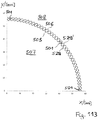
- a cross section of the tooth tips of the external toothing of the tensioning shaft corresponds essentially to a section of a circle.
- the cross section of the tooth tips thus corresponds to a cross section of a partial area of cylindrical pins and preferably essentially a semicircle.
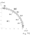
- the coordinates x and y relate to a right-angled coordinate system which is arranged perpendicular to the central axis of the external gear and has its origin in the central axis of the external gear or the transmission.
- the expansion shaft can be designed in a pot shape, a fastening area for fastening an output shaft being formed on the base of the pot shape. This can also be done in such a way that the tensioning shaft is formed in one piece with the output shaft.
- a central circular opening can be formed at the base of the pot shape, the fastening area of the clamping shaft having fastening holes which are arranged around the central circular opening.
- This embodiment which is not part of the invention, can be particularly advantageous for a geared motor.
- the tensioning shaft has the shape of a circular cylinder, the transmission having a second rotatably arranged outer wheel which has a fastening area for fastening an output shaft, the internal toothing of the outer wheel being of the same construction or The formula is determined like the internal toothing of the first external gear.
- the expression “essentially” in particular with regard to a toothing can refer to, for example, a maximum of 5% or 10% deviation with regard to what is described in the description with reference to FIG 117, 118 refer to the specified spacing dimensions.
- the shape of the external gear teeth can also be specified by explicitly specifying the epicyclic construction, according to which the tooth surface of the internal gear teeth of the external gear is determined by a radial distance from a central axis of the internal gear as a function of a cycle angle. The radial distance from the central axis is in turn determined by an inner equidistant to a wheel curve, a location on the wheel curve being determined by the vector sum of a cycle vector, a first epicyclic vector and a second epicyclic vector.
- a starting point of the cycle vector lies on the central axis
- a starting point of the first epicyclic vector lies at the end point of the cycle vector
- a starting point of the second epicyclic vector lies at the end point of the first epicyclic vector.
- an epicyclic angle of the first epicyclic vector is n + 1 times as large as the cycle angle and an epicyclic angle of the second epicyclic vector is n + 3 times as large as the cycle angle, where n is a number of pins of the harmonic pinring gear that is at least four is.
- a length of the cycle vector is greater than the sum of the lengths of the first epicyclic vector and the second epicyclic vector, and a length of the first epicyclic vector is greater than a length of the second epicyclic vector.
- two-stage reduction gear which is not part of the invention, which has an outer wheel fixedly attached to the gear housing and having a first internal toothing, the outer wheel having a fastening area for fastening to a gear housing.
- An outer wheel rotatably mounted on the transmission housing is provided with a second internal toothing, the outer wheel having a fastening area for fastening to an output shaft.
- a two-part or two-section but still one-piece pin ring is arranged concentrically to the outer gears, the two-part one-piece pin ring having a first external toothing and a second external toothing.
- the first external toothing of the two-part one-piece pin ring engages with the internal toothing of the stationary outer wheel.
- the second external toothing of the two-part one-piece pin ring engages with the internal toothing of the rotatable outer wheel.
- a rotating transmitter is designed to press the two-part, one-piece pin ring against the internal teeth of the stationary outer wheel and against the internal teeth of the rotatable outer wheel.
- a ball bearing is arranged on a circumference of the rotating transmitter.
- the number of teeth of the internal toothing of the stationary external gear can be greater than the number of teeth of the first external toothing
- the number of teeth of the internal toothing of the rotatable external gear can be greater than the number of teeth of the second external toothing the number of teeth of the stationary Outer gear is greater than the number of teeth of the rotatable outer gear and the number of teeth of the first external toothing is greater than the number of teeth of the second external toothing.
- the transmitter can have a circular ring arranged eccentrically to the axis of the stationary outer wheel.
- the eccentric gear offers a particularly simple and robust design, in which no deformable bearing is required.
- a cross section of the tooth tips of the first external toothing and a cross section of the tooth tips of the second external toothing can essentially correspond to a section of a circle, preferably a semicircle.
- the toothing geometry thus corresponds to cylindrical pins, which is particularly advantageous in the case of eccentric gears.
- the toothing can correspond to this shape along the entire circumference, and not only in the area of the tooth tips.
- this toothing form can apply to the toothing along the entire circumference, and not only in the area of the tooth tips.
- the present description discloses a load cell for determining a radial force on a crankshaft with a receiving sleeve for receiving a ring of a bearing, a fastening ring for fastening the load cell in a gear housing, and axial support areas which are provided on the fastening ring for axially supporting the ring of the bearing are.
- measuring areas for absorbing radial forces of the receiving sleeve are provided, which connect the receiving sleeve to the fastening ring, with strain sensors being attached to at least two of the measuring areas.
- the present description discloses a freewheel arrangement with an outer transmission freewheel and an inner pedal shaft freewheel, which is not part of the invention.
- the freewheel arrangement has a hollow drive shaft, a hollow output shaft, and a pedal shaft.
- the pedal shaft, the hollow output shaft and the hollow drive shaft are arranged concentrically to one another.
- the output hollow shaft is arranged radially inside the input hollow shaft, and the pedal shaft is arranged radially inside the output hollow shaft, the pedal shaft freewheel being arranged between the pedal shaft and the output hollow shaft.
- the gearbox freewheel is arranged opposite the Tretwell freewheel on the output hollow shaft.
- the output hollow shaft has adapted areas on an inside and on an outside in the area of the respective freewheel.
- the double freewheel can thus be integrated into the drive in a space-saving manner in the area of the pedal shaft without the need for a separate outer ring or inner ring.
- the outer freewheel can in particular be a clamping roller freewheel and the inner freewheel can be in particular a pawl freewheel.
- both freewheels can also be clamping roller freewheels. Other combinations are also possible.
- the present description discloses a one-piece pin ring, which is preferably used in connection with an eccentric gear, which is not part of the invention.
- the one-piece pin ring is made of metal, a pin retaining ring and an arrangement of pins that protrude in the axial direction on two opposite sides from the pin retaining ring, made from one piece is.
- the pins can be connected to one another in the circumferential direction, which offers additional stability and can enable more efficient production.
- the pins on a first of the two opposite sides can be designed as half pins that are suitable for engaging an internal toothing
- the pins on a second of the opposite side can be designed as whole pins that are designed to engage with an internal toothing and to engage are suitable in an external toothing opposite the internal toothing.
- the one-piece pin retaining ring has a smooth inner circumference on an inner side and rounded ones on an outer side Bulges on, which are made in one piece with the pin retaining ring.
- This embodiment which is not part of the invention, is suitable, for example, for a two-stage reduction gear with an eccentric.
- At least one head region of the rounded bulges can have a semicircular cross section. This means that the same teeth can be used that are also suitable for a pin ring with cylindrical pins.
- the present description discloses a support ring arrangement for a reduction gear, which is not part of the invention, with a first external gear and a second external gear which has a support ring, a first external gear with a first internal gear and a second external gear with a second internal gear, wherein the first outer wheel and the second outer wheel are inserted into the support ring on opposite sides, and wherein the support ring has a fastening area, for example axial bores, for fastening to a transmission housing.
- first outer wheel and the second outer wheel can be made of plastic. Furthermore, the first outer wheel and the second outer wheel can each be connected to the support wheel via a pin and groove connection, so that they can be easily assembled.
- a one-piece rotor transmitter element for a reduction gear which is not part of the invention, which has a hollow shaft which has a fastening region for fastening a rotor package on a first side and on an opposite side to the first side second side has a cam, wherein an outer circumference of the cam is designed as a receiving area for a ball bearing.
- the one-piece rotor transmitter element can be made of aluminum.
- the hollow shaft of the one-piece rotor-transmitter element can be dimensioned such that a pedal shaft can be passed through the hollow shaft.
- the cam has a circular circumference which is arranged eccentrically to the central axis of the hollow shaft.
- the cam disk has an oval circumference relative to the central axis of the hollow shaft.
- the crank mechanism has a drive shaft, in particular a crankshaft or pedal shaft with a planetary gear arranged on the drive shaft, a planet carrier of the planetary gear being firmly connected to the drive shaft, a ring gear of the planetary gear having a fastening area for fastening to a gear housing and a receiving area for a torque sensor, and a sun gear of the planetary gear being designed as a ring gear, that is arranged concentrically to the drive shaft, and wherein the sun gear is connected to a hollow output shaft of the planetary gear, which is rotatably mounted on the drive shaft.
- the crank gear has a drive shaft, in particular a crankshaft or pedal shaft, with a planetary gear arranged on the drive shaft, a planet carrier of the planetary gear being mounted on the drive shaft via a freewheel, a sun gear of the planetary gear has a fastening area for fastening to a gear housing and a receiving area for a torque sensor, and a ring gear of the planetary gear has a receiving area for a ball bearing to be supported on a gear housing.
- the crank gear has a drive shaft, in particular a crankshaft or pedal shaft, with a planetary gear arranged on the drive shaft, a planet carrier of the planetary gear having a fastening area for fastening to a gear housing, with a hollow shaft of the planetary gear is fixedly connected to the drive shaft, and wherein a sun gear of the planetary gear is designed as a hollow shaft which is arranged concentrically to the drive shaft rotatably on the drive shaft.
- a cycloid gear which is not part of the invention, the cycloid gear having the following components: a gear housing, an outer gear with internal teeth, which is attached to the gear housing, and a concentric to the Input shaft arranged on the outer wheel, the input shaft having a drive-side eccentric disk on which a first ball bearing is arranged and an output-side eccentric disk on which a second ball bearing is arranged.
- An internal gear on the drive side with external teeth is mounted on the first ball bearing and an internal gear on the output side with external teeth is mounted on the second ball bearing.
- the drive-side internal gear and the driven-side internal gear are arranged inside the external gear, and the external gears of the drive-side internal gear and the driven-side external gear each mesh with the internal gear of the external gear.
- the cycloid transmission can have a crankshaft that is mounted within the input shaft, and the previously described load cell, which is mounted on the drive side on the crankshaft.
- the input shaft can be designed as a one-piece rotor transmitter element described above.
- the cycloid gear has a crankshaft which is supported within the input shaft, and wherein the crankshaft has one of the planetary gears described above, the crankshaft forming the drive shaft of the planetary gear.
- a third ball bearing is arranged on the input shaft on the output side of the eccentric disk on the output side, an output disk being arranged on the third ball bearing, the output disk having drive pins which are axially arranged one behind the other in openings of the drive side Engage the inner gear and the output-side inner gear, an output shaft being formed radially on the inside on the output disk.
- an output shaft can be formed radially on the inside on the output disk, the third ball bearing being arranged on an inner shoulder of the output shaft. Furthermore, an inner wheel ball bearing is arranged diagonally opposite relative to the center points of the bearings in the axial direction to the third ball bearing on an outer shoulder of the output shaft, the inner wheel ball bearing being supported on a housing cover of the transmission housing.
- At least one of the internal gears has a first toothing and a second external toothing.
- the cycoid gear furthermore has a rotatable outer gear with internal teeth, the second external teeth engaging the internal teeth of the rotatable outer gear, and the rotatable outer gear having a fastening area for fastening an output shaft.
- the internal toothing can be formed by an inner surface of the outer wheel or else formed by an arrangement of stationary pins on which rollers are arranged.
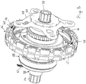
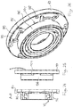
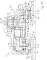
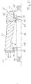
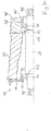
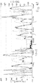
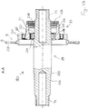
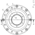
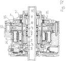
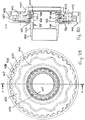
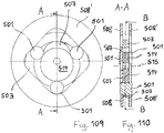
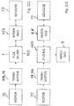
- FIG. 1 Figure 10 shows a cross-sectional view of a harmonic pinring transmission 10 not forming part of the invention.
- the cross-sectional plane AA of the Fig. 1 is in Fig. 9 marked.
- the left side corresponds to a drive side and the right side to an output side of the harmonic pinring transmission 10.
- the viewing direction is from Fig. 10 directed in the direction of travel.
- a stator 20 of a stator assembly of the harmonic pinring gear mechanism 10 is arranged in a motor housing 22.
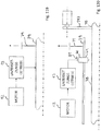
- the stator 20 has three separate coils 21 for connection to three phases of a three-phase inverter.
- the three coils of the stator 20 are connected to the three-phase inverter by three terminals 25, one of which in Fig. 1 is shown.
- the three-phase inverter is designed as power electronics which are arranged on a printed circuit board 23, the printed circuit board 23 being arranged in a cooling cover 24 which is placed on the motor housing 22 on the drive side.
- the circuit board 23 is designed as an annular disk which is located outside of cylindrical protruding sections of the motor housing and the cooling cover, so that the motor electronics located on it are sealed against oil and grease from the transmission.
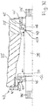
- a pedal shaft 35 running through the center of the motor housing 22 is stepped on the output side and has three steps, the diameter of which increases from the outside inwards and on each of which the shaft sealing ring 50, the output-side pedal shaft ball bearing 46 and the pedal shaft freewheel 49 are arranged.
- the diameter of the pedal shaft 35 is also graduated on the drive side and has two steps, the shaft sealing ring and a sensor ring 68 being arranged on the outer step and the ball bearing 45 being arranged on the inner step.
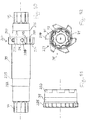
- the gradation of the pedal shaft is also shown in the perspective view of Fig. 4 shown.
- This outer rotor shaft is also referred to as a "rotor package”.
- the outer rotor shaft 26 On its inside, the outer rotor shaft 26 has an elastic region that is on an inner rotor shaft 27 is attached.
- An eccentrically arranged oval cam disk 28 is formed on the output side of the inner rotor shaft 27, which is shown in FIG Fig. 3 is shown in more detail.
- the inner rotor shaft 27 is supported on the drive side to the outside by a drive-side rotor ball bearing 29 in the motor housing 22.
- a drive-side rotor ball bearing 29 in the motor housing 22.
- an outer ring of the drive-side rotor ball bearing 29 is arranged in a cylindrical recess of the motor housing 22.
- the inner rotor shaft 27 is supported on the output side in an output-side rotor ball bearing 30 radially outward in an inner wheel 7.
- a hollow shaft of the internal gear 7 is integrally connected on the output side to an annular region of the internal gear 7, which has an external toothing 5.
- the hollow shaft of the inner wheel 7 is in turn supported radially outward via an inner wheel ball bearing 31 on a housing cover 32 which is screwed to the motor housing 22 by screws 33.
- the inner wheel ball bearing 31 is offset from the output-side rotor ball bearing 30 in the axial direction towards the output side and is offset outwards in the radial direction.
- the inner wheel ball bearing 31 overlaps with the output-side rotor ball bearing 30 in the axial direction.
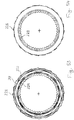
- a flexible ball bearing or thin-section ball bearing 33 in which an inner ring and an outer ring are deformable, is clamped on the cam disk 28 of the inner rotor shaft 27.
- a pin retaining ring 103 with pins 101 rests on the flexible ball bearing 33, the pins 101 being held in cylindrical recesses on the inside of a pin retaining ring.
- the pins 101 are connected to one another.
- the pins 101 of the pin ring 103 protrude in the axial direction on both sides over the flexible ball bearing 33 and the pin retaining ring 103.
- the pin ring arrangement comprising pin retaining ring 103 and pins 101 is also referred to as pin ring 102 in the following.
- the cam 28 and the flexible ball bearing 33 together form a transmitter arrangement which converts a torque into a radial force.
- a flexible ball bearing with a flexible inner and outer ring a wire roller bearing or a flexible ball bearing without an outer ring, or a different type of flexible roller bearing can be used.
- the housing cover 32 is screwed onto the motor housing on the output side of the motor housing with fastening screws 34. Furthermore, an external gear 8 'on the drive side and an external gear 8 on the driven side are inserted into a support ring 36 and screwed tight to the support ring 36 by the screws 34.
- the support ring 36 is divided in the axial direction into two mirror-symmetrical halves which together form a track 67 for the pin holding ring 103.
- the drive-side external gear 8 ′ and the driven-side external gear 8 are arranged in the axial direction outside the cam disk 28 and the flexible ball bearing 33.
- the drive-side outer wheel 8 ′ faces in the radial direction the areas of the pins 101 which protrude on the drive side in the axial direction beyond the pin retaining ring 103.
- the output-side outer wheel 8 faces in the radial direction the areas of the pins 101 which protrude beyond the pin-retaining ring 103 on the output side in the axial direction.
- a drive-side thrust ring 37 is arranged in the motor housing 22 in such a way that it faces the drive-side end faces of the pins 101 in the axial direction.
- an output-side thrust ring 38 is arranged in the motor housing 22 in such a way that it faces the output-side end faces of the pins 101 in the axial direction.
- An output shaft 39 is arranged radially inside the hollow shaft of the inner gear 7, a gearbox freewheel 40 being arranged between the hollow shaft of the inner gear 7 and the output shaft 39.
- the output shaft 39 is supported radially outward in an output-side output ball bearing 41 which is inserted into a cylindrical recess or shoulder of the housing cover 32.
- the output-side area of the output shaft 39 protrudes beyond the housing cover 32 in the axial direction.
- a chainring adapter 43 is placed on the output shaft 39, which is held in place by a round output nut 44 which is screwed into an internal thread of the output shaft 39.
- the pedal shaft 35 is arranged concentrically to the rotor shaft 27 and to the output shaft 39 partly in the interior of the rotor shaft 27 and partly in the interior of the output shaft 39.
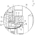
- the pedal shaft 35 is mounted radially outward via a drive-side pedal shaft ball bearing 45 in a load cell 47, which in turn is inserted into the motor housing 22.
- a printed circuit board 48 also referred to as a “PCB force sensor”, with evaluation electronics is attached to the load cell 47 and a connector on the printed circuit board 48 is routed radially outward via a ribbon cable 63 and connected to the electronics on the printed circuit board 23.
- the load cell 47 has strain gauges which generate electrical signals which correspond to a deformation of the load cell 47 serving as the suspension of the drive-side pedal shaft ball bearing.
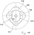
- the load cell 47 has four webs which are arranged at 45 degrees spacing in the circumferential direction and which are connected to a ring in which the outer ring of the bottom bracket ball bearing on the output side is inserted.
- a strain gauge which is electrically connected to the ring-shaped printed circuit board 22, is applied to each of these webs.
- a pedal shaft freewheel 49 is arranged between the pedal shaft 35 and the output shaft 39.
- the gearbox freewheel 40, the hollow shaft of the internal gear 7 and the internal gear ball bearing 31 connect radially outward.
- two adjacent freewheels or a single freewheel and an adjacent roller bearing, such as a needle bearing can be installed.
- an inner shaft sealing ring 50 is inserted between the pedal shaft 35 and the output shaft 39. Furthermore, an outer shaft sealing ring 51 is arranged opposite the output-side output ball bearing 46 between the output shaft 39 and the housing cover 32. Another shaft sealing ring 52 is arranged on the drive side between the cooling cover 24 and the pedal shaft 35. An O-ring 42 is inserted radially on the outside between the output-side outer wheel 8 and the housing cover 32.
- an input torque is transmitted from the stator 20 to the outer rotor shaft 26 and from there to the inner rotor shaft 27 through the action of electromagnetic force, which torque is converted into a radial force by the cam disk 28 and the flexible ball bearing 33.
- This radial force is converted into an output torque on the tooth flanks of the internal gears 6, 6 'of the external gears 8, 8' and the external gears 5 of the internal gear 7, the internal gear 7 being driven off and the external gears 8, 8 'being fixed to the housing .
- the output torque is greater than the input torque by the reduction ratio.
- the internal toothing which is formed by the external toothing 5 of the internal gear 7, lies opposite the internal toothing 6 of the output-side external gear 8, and thereby provides the output torque, in particular through those pins 101 that are located on both the external toothing 5 and the internal toothing 6 , 6 'are applied.
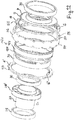
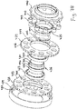
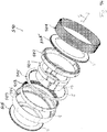
- FIG. 13 shows an exploded view of the transmission of FIG Fig. 1 , in which, seen from the drive side to the output side, the drive-side rotor ball bearing 29, the inner rotor shaft 27, the cam disk 28, the output-side rotor ball bearing 30, the second outer wheel 8 ', the flexible ball bearing 33, the pin retaining ring 103 the pins 101, the support ring 36, the first external gear 8, the internal gear 7 with the internal gear hollow shaft and the internal gear ball bearing 31 are shown.
- the outer gears 8, 8 'each have pins 53 which protrude radially outward from the respective outer gear 8, 8' and are distributed at regular intervals over the circumference of the outer gear 8, 8 '.
- the support ring 36 has radial slots 54 distributed around the circumference and matching the pins 53 on radially opposite sides.
- Screw holes 55 are provided, which in the embodiment of Fig. 2 , which is not part of the invention, are partly in the outer gears 8, 8 'and partly in the support ring 36.
- a wave spring 61 is arranged between the drive-side rotor ball bearing 29 and the motor housing 22 on the drive side of the drive-side rotor ball bearing 29 and a spacer ring 62 is arranged between the drive-side rotor ball bearing 29 and the outer rotor shaft 26 on the driven side of the drive-side rotor ball bearing 29 .
- the support ring 36 can consist of aluminum and the outer wheels 8, 8 'of plastic, such as polyamide 66 (PA66), whereby the support ring 36 can be made in particular by aluminum die-casting, and the outer wheels in particular by plastic injection molding can.
- the inner rotor shaft 27 can be made of aluminum.
- the screws 34 in the assembled state extend through the gear cover 32, the first outer gear 8, the second outer gear 8 ′ and the support ring 36 into the motor housing 22.
- FIG. 13 shows a drive-side part of an exploded view of the transmission from FIG Fig. 1 , in which, seen from the drive side, the cooling cover 24, the circuit board 23, the motor housing 22 with the stator 20 and the coil 21 or with the coils 21, the circuit board 48, the load cell 47, the wave spring 61, the drive-side Thrust ring 37, the second outer wheel 8 'with the internal toothing 6', the drive-side rotor ball bearing 29, the spacer ring 62, the outer rotor shaft 26 and part of the inner rotor shaft 27 are shown.
- FIG. 13 shows a driven part of an exploded view of the transmission from FIG Fig. 1 , in which, seen from the drive side, the inner rotor shaft 27 with the cam disk 28, the output-side rotor ball bearing 30, the pin ring 102 with the pin retaining ring 103 and the pins 101, the support ring 36, the output-side outer wheel 8, the Inner gear 7 with the external toothing 5, the output shaft 37, the gear free wheel 40, the O-ring, the output-side thrust washer 38, the inner gear ball bearing 31, the housing cover 32 with the fastening screws 34 and the shaft sealing ring 50 are shown.
- the gear freewheel 40 has, as in Fig. 3 shown, coil springs on cylindrical rollers 64 which are arranged in a sprag cage 65. In order to press on the cylindrical rollers 64, helical springs 66 are also provided in the clamping body cage 65.
- FIG. 13 shows an exploded view of an internal assembly of the transmission of FIG Fig. 1 , and in particular the pedal shaft freewheel 49.
- Shows in detail Fig. 4 seen from the drive side, a sensor ring 68, the drive-side pedal shaft ball bearing 45, the pedal shaft 35, the pedal shaft freewheel 49, the driven-side pedal shaft ball bearing 46, a spacer 69, a chainring adapter 43, a wave spring 70, an inner shaft seal 50, an O-ring 76 and the output nut 44.
- the pedal shaft freewheel 49 has, as in Fig. 4 shown, vane-shaped steps 71 which are formed on the pedal shaft 35. Pawls 73 and coil springs 72 are arranged between the steps 71. Fastening areas 74, 75 for cranks are arranged at both ends of the pedal shaft, which are shown in FIG Fig. 1 are shown in cross section.
- FIG. 13 is a perspective view of an internal assembly of the transmission of FIG Fig. 1 when assembled.
- the internal gear 7 and the flexible ball bearing 33 are omitted.
- FIG. 8 shows a pedal shaft assembly 80 or pedal shaft unit 80 of the transmission 10 of FIG Fig. 1 , with the drive side on the right and the driven side on the left.
- the pedal shaft assembly 80 has a freewheel arrangement 81 and a sensor arrangement 82.
- the direction of view of the view from Fig. 6 is in the opposite direction when installed.
- FIG. 11 shows a cross section through the freewheel arrangement 81 from FIG Fig. 6 along the section line DD, which is viewed from the output side, the flat cable 63 belonging to the sensor arrangement 82 being visible in the background. Furthermore, on the right-hand side of the load cell 47, the screw heads of the screws can be seen with which the ring-shaped printed circuit board 23 is screwed to the load cell 47.
- the freewheel arrangement 81 has the pedal shaft freewheel 49 and the gear freewheel 40, the output shaft 39 being designed at the same time as the outer ring of the pedal shaft freewheel 49 and as the inner ring of the gear freewheel 40.
- the pedal shaft freewheel 49 is designed as a pawl freewheel while the gear freewheel 40 is designed as a pinch roller free wheel with cylindrical pinch rollers 64.
- the inner circumference of the output shaft 39 forms a serrated staircase, the steps of which form stops for the pawls 73, which are pressed against the inner circumference of the output shaft 39 by the helical springs 72.
- the outer circumference of the output shaft 39 forms a serrated staircase, also referred to as a “star”, the steps of which form stops for the cylindrical rollers 64 of the gear free wheel 40.
- the freewheel cage 65 and thus the cylindrical rollers 64 are supported by the helical springs 66, which are arranged between the outer circumference of the output shaft 39 and the freewheel cage 65, pressed against the outer circumference of the drive shaft 39.
- the steps of the drive shaft 39 are arranged in such a way that a freewheeling direction of the pedal shaft freewheel 49 and a freewheeling direction of the gear freewheel 40 in the view of FIG Fig. 7 counterclockwise. This freewheeling direction is reversed to the respective drive direction or blocking direction.
- the pedal shaft 35 can drive the output shaft 39 clockwise as long as the output shaft 39 does not move faster than the pedal shaft 35 and the outer ring of the gear free wheel 40, which is formed by an inner area of the inner gear 5, the output shaft 39 can be clockwise drive as long as the output shaft 39 does not move faster than the outer ring.
- the drive and blocking directions of the freewheels 40, 49 are shown in FIG Fig. 7 each indicated by arrows.
- FIG. 13 shows a simplified cross-sectional view showing the components in the transmission of FIG Fig. 1 used load cell 47 and the use of an inclined bearing is illustrated.
- the electric motor and the drive train of the electric motor are omitted in this illustration, so that the pedal shaft 35 is mounted directly on a housing cover 32 '.
- the drive-side pedal shaft ball bearing 45 and the driven-side pedal shaft ball bearing 46 are each designed as an angular contact ball bearing that can absorb axial forces to a certain extent.
- ball bearings other types of bearings can also be provided which, in addition to radial forces, can also absorb axial forces, such as, for example, tapered roller bearings.
- this is usually more complex than using ball bearings.
- the load cell 47 which is mounted on the pedal shaft 35 via the bearing 45, has support brackets 91 and measuring brackets 90.
- the support plates 91 are supported in the axial direction on an outer ring of the ball bearing and the measuring plates 90 are supported in the radial direction on the outer ring.
- Strain gauges are attached to at least two of the 90 measuring straps.
- the inner ring of the ball bearing 45 rests against a shoulder or a shoulder of the pedal shaft 35 towards the center of the pedal shaft 35.
- the inner ring of the ball bearing 46 rests towards the center of the pedal shaft 35 via a wave spring 70 on a shoulder of the pedal shaft 35.
- the outer ring of the ball bearing 46 rests on the gear cover 44 'via a spacer washer.
- a driver transmits radial forces to the pedal shaft 35 via a pedal crank. These radial forces are absorbed by the measuring tabs 90 and lead to a deformation of the measuring tabs 90, which is determined by the strain gauges. In contrast, axial forces on the outer ring of the ball bearing 45 do not lead to a deformation of the second link plates. Instead, the axial forces are absorbed by the support tabs 91 of the load cell 47, as a result of which the ball bearing 45 is held laterally.
- any torque that may be present due to an auxiliary drive does not, or only insignificantly, lead to a deformation of the second tabs.
- the driver's contribution can be determined for himself.
- an angular position sensor can be provided, with the aid of which the position of the cranks can be determined and thereby the lever arm of the pedals.
- the torque provided by the driver can be reconstructed from the measured radial forces using a suitable computational model that is implemented by a stored program and / or circuit.
- Figure 10 illustrates a derivation of axial forces into the housing according to the bearing concept of the transmission of Figures 1 to 9 .
- a drive-side axial force of the pedal shaft 35 is diverted into the housing 22 via a drive-related shoulder 123 of the pedal shaft 35, the drive-side pedal shaft ball bearings 45, axial support brackets of the load cell 47 and a fastening ring of the load cell 47.
- an output-side axial force of the rotor shaft 28 is diverted via the output-side rotor ball bearing 30, the internal gear 7 and the internal gear ball bearing 31 into the housing cover. From there, the axial force is diverted into the housing 22 via the screws 34, as shown at the bottom right in FIG Fig. 10 shown.
- a drive-side axial force of the rotor shaft 27 is diverted into the housing 22 via a shoulder 9 of the rotor shaft 27, the outer rotor shaft 26, the spacer ring 62, the drive-side rotor ball bearing 29 and the wave spring 61.
- an axial force on the ball bearing 33 arranged on the cam disk is diverted into the gear housing 22 via the internal gear 7 and the ball bearing 31.
- the counterforce to it is diverted via a shoulder 9 of the cam 28 into the rotor shaft 27 and from there into the housing 22 via the route described above.
- the inner wheel 7 tapers radially inward of an outer circumference, so that only the outer ring of the ball bearing 33 rests against the inner wheel 7, which moves essentially synchronously with the pin ring 101 and with the inner wheel 7, and not the inner ring of the ball bearing 33, which much faster than the inner wheel 7 rotates.
- the width of the wave spring 70 is set so that the chainring adapter 43 does not hit the housing cover 32.
- the Figures 11 to 20 show a harmonic pinring gear, which is not part of the invention, with an eccentric cam disc, the eccentric cam disc being an eccentrically arranged circular disc.
- FIG. 13 shows a cross-sectional view of a harmonic pinring transmission 10.
- the cross-sectional plane AA of FIG Fig. 11 is in Fig. 19 marked.
- the left side corresponds to a drive side and the right side corresponds to an output side of the harmonic pinring transmission 10.
- a stator 20 of a stator assembly of the harmonic pin-ring transmission 10 is arranged in a motor housing 22.
- the stator 20 has three separate coils 21 for connection to three phases of a three-phase inverter.
- the three-phase inverter is designed as power electronics which are arranged on a printed circuit board 23, the printed circuit board 23 being arranged in a cooling cover 24 which is placed on the motor housing 22 on the drive side.
- the three coils of the stator 20 are connected to the three-phase inverter by three terminals 25, one of which in Fig. 11 is shown.
- the motor housing 22 and the cooling cover 24 each have cylindrical protruding sections which enclose a pedal shaft 35 running centrally through the motor housing 22.
- the circuit board 23 is designed as a perforated disk which is located outside the protruding sections, so that the electronics located on it are sealed against oil and grease from the transmission.
- This outer rotor shaft 26 is also referred to as a “rotor package”.
- the outer rotor shaft 26 On its inside, the outer rotor shaft 26 has an elastic region which is pushed onto an inner rotor shaft 27.
- An eccentrically arranged circular eccentric disk 28 ' is formed on the output side of the inner rotor shaft 27, which is shown in FIG Fig. 12 is shown in more detail.
- the inner rotor shaft 17 is supported on the drive side to the outside by a drive-side rotor ball bearing 29 in the motor housing 22.
- a drive-side rotor ball bearing 29 in the motor housing 22.
- an outer ring of the drive-side rotor ball bearing 29 is arranged in a cylindrical recess of the motor housing 22.
- the inner rotor shaft 27 is supported on the output side in an output-side rotor ball bearing 30 radially outward in an inner wheel 7.
- a hollow shaft of the internal gear 7 is integrally connected on the output side to an annular region of the internal gear 7, which has an external toothing 5.
- the hollow shaft of the inner gear 7 is in turn mounted radially outward via an inner gear ball bearing 31 on a housing cover 32 which is screwed to the motor housing 22 by screws 34.
- the inner wheel ball bearing 31 is offset from the output-side rotor ball bearing 30 in the axial direction towards the output side and is offset outwards in the radial direction.
- the inner wheel ball bearing 31 overlaps with the output-side rotor ball bearing 30 in the axial direction.
- a ball bearing 33 is clamped on the eccentric circular disk 28 of the inner rotor shaft 27.
- a pin retaining ring 103 with pins 101 rests on the ball bearing 33, the pins 101 being held in cylindrical recesses on the inside of a pin retaining ring.
- the pin ring arrangement of pins 101 and pin retaining ring 103 is in the Figures 15 to 17 shown in more detail.
- the pin ring 103 unlike in the embodiment of FIG Figures 1 to 10 , which is also not part of the invention, molded from one piece and has areas that correspond to the pins 101 and the pin retaining ring 103.
- the one-piece embodiment of the pin ring 103 which is not part of the invention, is particularly suitable for a transmission in which the pin ring is not or only insignificantly deformed.
- the eccentric disk 28 'and the ball bearing 33 together form a transmitter arrangement which converts a rotary movement into a radial movement, which is transmitted through the ball bearing 33 and the pin ring 103 to the pins 101, and which is then transmitted by the engagement of the pins 101 in the outer gears 8, 8 'is converted back into a rotary movement.
- the housing cover 32 is screwed onto the motor housing on the output side of the motor housing with fastening screws 34. Furthermore, there is an external gear 8 'on the drive side and an external gear 8' on the output side Outer wheel 8 inserted into a support ring 36 and by the screws 34 on the Support ring 36 screwed tight. An O-ring 42 is inserted radially on the outside between the output-side outer wheel 8 and the housing cover.
- the drive-side outer wheel 8 'and the driven-side outer wheel 8 are arranged in the axial direction outside the eccentric disk 28' and the ball bearing 33.
- the drive-side outer wheel 8 ′ faces in the radial direction the areas of the pins 101 which protrude on the drive side in the axial direction beyond the pin retaining ring 103.
- the output-side outer wheel 8 faces in the radial direction the areas of the pins 101 which protrude beyond the pin-retaining ring 103 on the output side in the axial direction.
- a drive-side thrust ring 37 is arranged in the motor housing 22 in such a way that it faces the drive-side end faces of the pins 101 in the axial direction.
- an output-side thrust ring 38 is arranged in the motor housing 22 in such a way that it faces the output-side end faces of the pins 101 in the axial direction.
- An output shaft 39 is arranged radially inside the hollow shaft of the inner gear 7, a gearbox freewheel 40 being arranged between the hollow shaft of the inner gear 7 and the output shaft 39.
- the output shaft 39 is supported radially outward in an output-side output ball bearing 41 which is inserted into a cylindrical recess or shoulder of the housing cover 32.
- the output-side area of the output shaft 39 protrudes beyond the housing cover 32 in the axial direction.
- a chainring adapter 43 is placed on the output shaft 39, which is held in place by a gear cover 44 which is screwed into an internal thread of the output shaft 39.
- the above-mentioned pedal shaft 35 is arranged concentrically to the rotor shaft 27 and to the output shaft 39 partly in the interior of the rotor shaft 27 and partly in the interior of the output shaft 39.
- the pedal shaft 35 is mounted radially outward via a drive-side pedal shaft ball bearing 45 in a load cell 47, which in turn is inserted into the motor housing 22.
- a circuit board 48 with a force sensor is attached to the load cell 47 and a connection of the circuit board 48 is led radially outward via a flat cable 63 and connected to the electronics on the circuit board 23.
- a pedal shaft freewheel 49 is arranged between the pedal shaft 35 and the output shaft 39.
- the gearbox freewheel 40, the hollow shaft of the internal gear 7 and the internal gear ball bearing 31 connect radially outward.
- two adjacent freewheels or a single freewheel and an adjacent roller bearing, such as a needle bearing can be installed.
- an inner shaft sealing ring 50 is inserted between the pedal shaft 35 and the output shaft 39. Furthermore, an outer shaft sealing ring 51 is arranged opposite the output-side output ball bearing 46 between the output shaft 39 and the housing cover 32. Another shaft sealing ring 52 is arranged on the drive side between the cooling cover 24 and the pedal shaft 35.
- an input torque is transmitted from the stator 20 to the outer rotor shaft 26 and from there to the inner rotor shaft 27 through the action of electromagnetic force, which torque is converted into a radial force by the eccentric disk 28 'and the ball bearing 33.
- This radial force is converted into an output torque on the tooth flanks of the internal gears 6, 6 'of the external gears 8, 8' and the external gears 5 of the internal gear 7, the internal gear 7 being driven off and the external gears 8, 8 'being fixed to the housing.
- the output torque is greater than the input torque by the reduction ratio.
- the internal toothing which is formed by the external toothing 5 of the internal gear 7, lies opposite the internal toothing 6 of the output-side external gear 8, and thus provides the output torque, in particular through those pins 101 that are both on the external toothing 5 and on the Internal gears 6, 6 'are in contact.
- FIG. 13 shows an exploded view of the transmission of FIG Fig. 11 , in which, seen from the drive side to the output side, the drive-side rotor ball bearing 29, the inner rotor shaft 27, the eccentric disk 28 ', the output-side rotor ball bearing 30, the second outer wheel 8', the ball bearing 33, the pin retaining ring 103 with the pins 101, the support ring 36, the first external gear 8, the internal gear 7 with the internal gear hollow shaft and the internal gear ball bearing 31 are shown.
- the outer wheels 8, 8 'each have pins 53 which protrude radially outward from the respective outer wheel 8, 8' and are distributed at regular intervals over the circumference of the outer wheel 8, 8 '.
- the support ring 36 has radial slots 54 distributed around the circumference and matching the pins 53 on radially opposite sides.
- screw holes 55 are provided for fastening the outer wheels, which in the embodiment of FIG Fig. 12 , which is not part of the invention, are partly in the outer gears 8, 8 'and partly in the support ring 36.
- a wave spring 61 is arranged on the drive side of the drive-side rotor ball bearing 29, and between the drive-side rotor ball bearing 29 and the outer rotor shaft 26 is on the output side of the drive-side rotor Ball bearing 29 a spacer ring 62 is arranged.
- the support ring 36 can be made of aluminum and the outer wheels 8, 8 'made of plastic, such as polyamide 66 (PA66), wherein the support ring 36 can be made in particular by aluminum die casting, and the outer wheels in particular by plastic injection molding could be.
- the inner rotor shaft 27 can be made of aluminum.
- the screws 34 in the assembled state extend through the gear cover 32, the first outer gear 8, the second outer gear 8 ′ and the support ring 36 into the motor housing 22.
- Fig. 13 shows a side view, seen from the output side, of an assembled arrangement of inner rotor shaft 27, inner gear 7, pins 101 and outer gear 8.
- the pins 101 lie completely against the outer internal toothing 6 in a first position and completely against the inner external toothing 5 in a second position, which is opposite the first position.
- FIG. 14 shows a cross-sectional view through the arrangement of FIG Fig. 13 along the section line EE.
- the eccentric disk 28 ' has a shoulder 11 on the drive side, by means of which an inner ring of the ball bearing 33 is held in place from the drive side.
- FIG. 14 shows an output-side view of a pin ring 102 for use in the transmission of FIG Fig. 11 .
- the Figures 16 and 17 FIG. 10 shows detailed views of the pin ring 102 from FIG Fig. 15 and Figure 18
- FIG. 14 shows a drive-side view of pin ring 102 from FIG Fig. 15 .
- the pin ring 102 has a pin retaining ring 103 and pins 101.
- the pin ring 102 is formed in one piece, the pin retaining ring 103 and the pins 101 each being formed by regions of the pin ring 102 which is formed in one piece.
- the pins 101 are each shaped differently on an output side and on an opposite drive side.
- the pins on the output side of the pin ring 102, on which the pins 101 engage both the inner wheel 7 and the outer wheel 8, are lens-shaped, two radially opposite areas each having a segment-shaped boundary and two peripherally opposite areas each pointed run towards. This is best seen in the side view of the Fig. 17 recognizable that in Fig. 15 marked with "G".
- the pins 101 on the drive side, on which the pins 101 only engage in the second outer wheel 8 ' are shaped as "half pins" which each form prongs of a comb which runs along the circumference of the pin ring 102, as in the cross-sectional view of FIG Fig. 16 and in the view of Fig. 18 shown.
- a first area 255 of a pin 101 is also shown, which transmits torque to the inner wheel 7 and a second radially opposite area 56, which transmits torque to the outer wheel 8.
- the areas of the pins 101 which taper to a point along the circumferential direction result in tangential transitions between the pins 101.
- the pin ring is produced by flow molding.
- a hollow ring is first produced, from which the pins 101 are then formed by parting or milling.
- a rotating milling machine can be used that moves on a circular line, the pins being shaped first from the inside and then from the outside in the radial direction.
- Flow molding is defined in more detail in the standards DIN 8582 and DIN 8583, for example.
- a workpiece to be formed is first placed on an assembly mandrel.
- the workpiece to be formed is then deformed from the outside by flow-forming wheels that are driven in a controlled manner by a feed drive, press against the workpiece and thin out the material in a controlled manner.
- a shoulder 57 is formed on the output side of the pins 101 radially on the inside. As in Fig. 11 As can be seen, this shoulder 57 rests in the installed state of the pin ring 102 on the output side on the outer ring of the ball bearing 33.
- a comb with round recesses 58 and plateaus 59 lying therebetween is formed on the drive side of the pin ring 102.
- the intermediate plateaus 59 form an extension of the in Fig. 17 Pins 101 shown in detail and can thus be understood as the drive-side area of pins 101.
- FIG. 13 shows an output side view of the assembled transmission from FIG Fig. 11 , in which the cross-sectional plane of the Figure 11 marked with "A".
- Figure 20 illustrates a derivation of axial forces into the housing according to the bearing concept of the transmission of Figures 11 to 19 .
- a drive-side axial force of the pedal shaft 35 is diverted into the housing 22 via a drive-related shoulder 123 of the pedal shaft 35, the drive-side pedal shaft ball bearings 45, axial support brackets of the load cell 47 and a fastening ring of the load cell 47.
- an output-side axial force of the rotor shaft 27 is diverted via the output-side rotor ball bearing 30, the inner wheel 7 and the inner wheel ball bearing 31 into the housing cover. From there, the axial force is diverted into the housing 22 via the screws 34, as shown at the bottom right in FIG Fig. 20 shown.
- a drive-side axial force of the rotor shaft 27 is diverted into the housing 22 via a drive-side shoulder of the rotor shaft 27, the outer rotor shaft 26, the spacer ring 62, the drive-side rotor ball bearing 29 and the wave spring 61.
- an axial force is diverted via a shoulder 9 of the cam disk 28 to the ball bearing 33 via a shoulder 10 of the pin ring 100, the internal gear 7 and the ball bearing 31 into the gear housing 22.
- the corresponding counterforce is diverted via the shoulder 9 of the cam disk 28 into the rotor shaft 28 and from there via the path described above into the housing 22.
- the inner wheel 7 tapers radially inward of an outer circumference, so that only the outer ring of the ball bearing 33 rests against the inner wheel 7, which moves essentially synchronously with the pin ring 101 and with the inner wheel 7, and not the inner ring of the ball bearing 33, which much faster than the inner wheel 7 rotates.
- the width of the wave spring 70 is set so that the chainring adapter 43 does not hit the housing cover 32.
- Figures 21 to 44 disclose devices and methods for measuring a torque which acts on a pedal shaft of a bicycle supported by an electric drive.
- the support of an electric motor for an electric bicycle can be set.
- Various methods are known for this.
- the torque can be measured without contact by a magnetic measurement of the tension the pedal wave can be determined.
- Another method is to determine a mechanical deformation of the bottom bracket suspension.
- a corresponding device is for example in the patent application DE 102013220871 A1 disclosed. According to this device, a single electromagnetic or mechanical sensor is used to determine a horizontal deflection or deformation of the bottom bracket suspension.
- the present description discloses a load cell for determining a radial force on a crankshaft with a receiving sleeve for receiving a ring of a bearing and a fastening ring for securing the load cell in a gear housing.
- Axial support areas are provided on the fastening ring for axially supporting the outer ring of the first bearing.
- Measuring areas that connect the receiving sleeve to the fastening ring are provided for absorbing radial forces of the receiving sleeve.
- Strain sensors are attached to at least two of the measuring areas.
- the strain sensors can in particular be designed as strain gauges, it being possible for the strain gauges to be glued to a surface of the measuring areas.
- the axial support areas and the measuring areas can in particular be designed as tabs or fingers. Furthermore, the measuring areas can be designed as angular tabs.
- the radial force on the crankshaft is determined indirectly by a radial force acting on the receiving sleeve, which in turn is passed on from the crankshaft to the receiving sleeve via a bearing.
- the crankshaft can in particular be a pedal shaft.
- the load cell can be used, in particular, in electric bicycles to regulate motor assistance, a pedal shaft being supported in the axial direction via the load cell.
- the load cell can be used wherever a radial force on a shaft is converted into a rotary movement of the shaft, especially in the case of a bicycle pedal shaft or a piston that is driven by an internal combustion engine or some other drive.
- the measurement of the radial forces via the load cell can allow the torque exerted on the shaft to be calculated.
- the radial forces can also be used to generate control signals without the intermediate step of calculating the torque.
- a load cell can also be used to determine an imbalance on the shaft.
- the load cell is particularly advantageous in the case of a mechanical drive such as a pedal shaft, since in this case the torque applied cannot already be determined via a motor output, which is easily possible with an electric motor, for example.
- radial and axial forces are decoupled in that axial forces are absorbed by the axial support areas or tabs and radial forces are absorbed by the measuring areas or tabs.
- the load cell can be used in an inclined mounting, such as, for example, in an O-arrangement or an X-arrangement.
- the decoupling of the radial from the axial forces can allow a more precise measurement of the radial force component, and thus a more precise determination of the torque applied to the shaft.
- a load cell according to the present description has a simple structure and requires little space in a transmission, in particular in the axial direction.
- the total width of the load cell is essentially determined by the width of the bearing and the width of the fastening area axially adjoining it. Therefore, the load cell can be built relatively narrow in the axial direction, for example it can only have about twice the width of a roller bearing or less.
- the absorption of the axial forces by the load cell is advantageously carried out on the stationary outer ring of the ball bearing and not on the movable inner ring or on the shaft, where the relative movement would lead to friction losses.
- the axial support areas are advantageously only in contact with the outer ring of the bearing.
- the support function of the axial support areas can in particular be achieved in that the axial support areas or tabs protrude radially inward over an inner surface of the receiving sleeve, it being sufficient if the axial support areas only protrude inward as far as corresponds to the width of a bearing ring.
- the axial support areas can furthermore have a profile for alignment on the bearing ring.
- the measuring tabs are expediently designed as angles, an axial area of the angle connected to the receiving sleeve running in the axial direction and a radial area of the angle connected to the fastening area running in the radial direction.
- the angle forms a lever arm that causes the radial area of the measuring tab to bend in relation to the radial alignment.
- a surface of the measuring tabs is stretched or compressed and a surface axially opposite thereto is compressed or stretched. This compression or stretching is recorded by the strain gauges which are applied to one of the two surfaces of the radial area.
- the two areas of the angle formed by the measuring tab can also be slightly inclined with respect to the axial or the radial alignment, for example in order to cause a greater deformation enable.
- the measuring tabs are advantageously sufficiently thin in the axial direction to enable good deformation.
- the second area can be made thinner than the first area.
- the second area near the apex of the angle can be reinforced in order to avoid deformation near the apex of the angle.
- the axial area of the measuring strap is advantageously designed so that it does not protrude beyond the surface of the receiving sleeve that rests on the roller bearing. This prevents a ring of a roller bearing, on which the receiving sleeve rests, from hitting the measuring strap and axial forces being transmitted via the measuring strap.
- the axial region can terminate or be designed to be flush with a surface of the receiving sleeve, the surface being a cylindrical inner surface of the receiving sleeve.
- the measuring areas have measuring tabs designed as angles or are designed as angular measuring tabs.
- the measuring tabs have a radial area and an axial area adjoining the radial area. The radial area is connected to the fastening ring and the axial area is connected to the receiving sleeve, the radial area being arranged at an angle of approximately 90 degrees to the axial area.
- measuring brackets are provided so that the shaft can be supported in four directions.
- the measuring tabs can be arranged at a distance of 90 degrees so that the directions are perpendicular to one another.
- the measuring brackets are also support brackets for radial support.
- the term "measuring tab" means that the deformation of the measuring tab can be used to measure forces that act on the receiving sleeve in the radial direction.
- an angular extension of the measuring tab in the circumferential direction can be selected to be suitable in order to detect a force in a defined direction and to enable good deformation.
- the angular extent of the measuring tab along the circumferential direction can be limited to 30 degrees or less or to 25 degrees or less, with 90 degrees corresponding to a right angle.
- the load cell has four measuring areas which are arranged at a distance of 90 degrees. This means that radial forces can be measured in four mutually perpendicular directions if all four measuring areas or measuring brackets are equipped with strain sensors.
- strain sensors can be designed as strain gauges, which are inexpensive and robust, in particular compared to an optical strain measurement.
- a strain sensor can be attached to each of the measuring areas or measuring brackets in order to measure radial forces in as many directions as possible.
- the surfaces of the measuring areas to which the strain gauges are attached can have recessed areas or pockets for attaching the strain sensors or strain gauges.
- strain gauges can be arranged near the fastening area, for example in order to keep the electrical connection to a circuit board fastened to the transmission housing as short as possible or because greater deformation occurs there.
- the axial support areas or tabs are separated from the measuring areas by radial slots. Furthermore, the axial support areas or tabs are separated from the receiving sleeve by a circumferential slot.
- the axial support areas and the measuring areas can thereby be formed in a simple manner from a workpiece.
- the load cell can also be cast in this form.
- the radial or circumferential slots are expediently straight slots in the radial or circumferential direction. However, the shape can also deviate from a straight line.
- the direction of the radial slots can deviate from a radial direction, for example in order to achieve that the measuring tab tapers more inwardly.
- the orientation of the radial slots can be inclined inwards by up to 5 degrees or by up to 10 degrees with respect to the radial direction.
- the fastening ring For fastening to the transmission housing, the fastening ring according to one exemplary embodiment has fastening areas in which fastening holes are provided.
- the fastening areas can be part of the fastening ring, or they can be extensions that protrude from the fastening ring.
- the fastening advantageously fixes the load cell both in the axial direction and against rotation in the circumferential direction, the fastening being able to be loosened again mechanically. According to another exemplary embodiment, this is also achieved by a form-fitting connection such as a tenon connection or a snap lock.
- connections that cannot be easily loosened, such as riveted or welded connections, are also possible. However, they are less suitable for maintenance purposes.
- the fastening ring has recesses, the measuring areas being arranged in the recesses, the recess being able to be shaped in the radial and in the axial direction.
- an angular extent of the measuring tabs and the slots delimiting the measuring tabs is approximately equal to an angular range of the axial support areas.
- an angular extent of the measuring areas in the circumferential direction is less than or equal to 30 degrees, so that the force can be measured in a defined direction.
- the design of a load cell according to the present description is particularly suitable for manufacturing the load cell integrally from metal, for example by casting from a mold and mechanical post-processing steps.
- the present description discloses a measuring device for determining a force on a crankshaft, in particular a pedal shaft.
- the measuring device has a crankshaft with a bearing arranged on the crankshaft, and a load cell according to one of the aforementioned exemplary embodiments.
- the receiving sleeve of the load cell is arranged on an outer ring of the bearing, the axial support areas of the load cell being supported in the axial direction on the outer ring of the bearing.
- Evaluation electronics are also connected to the strain sensors of the load cell.
- the gear arrangement has a gear housing and a crankshaft, in particular a pedal shaft.
- the crankshaft is received or supported directly or indirectly in the transmission housing via a first drive-side bearing and a second output-side bearing.
- the bearings can in particular be provided by roller bearings.
- crankshaft can be passed through a hollow output shaft, with a freewheel being arranged between the pedal shaft and the hollow drive shaft, in particular for decoupling the pedal shaft from the hollow drive shaft.
- the first bearing is received in the gear housing via the load cell, the load cell being received in the gear housing or attached to the gear housing via the fastening ring.
- the receiving sleeve receives an outer ring of the first bearing, the axial support areas being supported on the outer ring of the first bearing.
- the crankshaft of the gear arrangement has a larger diameter in the middle than at its two ends.
- a first shoulder and a second shoulder of the crankshaft are formed.
- An inner ring of the first bearing of the measuring device rests on the first shoulder of the pedal shaft, and an inner ring of the second bearing rests on the second shoulder of the pedal shaft.
- an X-arrangement of an inclined bearing is formed and the load cell absorbs part of the forces of the inclined bearing.
- the first bearing of the measuring device and the second bearing are each designed as single-row angular contact ball bearings. According to a further exemplary embodiment, the first bearing of the measuring device and the second bearing are each designed as inclined cylindrical roller bearings.
- the second bearing is supported via a wave spring on the second shoulder of the pedal shaft or on the housing or on a component connected to the housing.
- the second roller bearing is also supported via a spacer disc on the second shoulder of the pedal shaft or on the housing or on a component connected to the housing.
- the present description discloses a gear arrangement which also has the following features: a motor, a reduction gear connected to the motor, and a hollow output shaft connected to the reduction gear.
- the crankshaft is designed as a pedal shaft, the first bearing and the second bearing each being designed as roller bearings, the pedal shaft being passed through the hollow output shaft, and for decoupling the pedal shaft a freewheel between the pedal shaft and the hollow output shaft is provided by the output hollow shaft.
- the present description discloses an electrically operated vehicle, in particular an electric bicycle, with the transmission arrangement described above, the motor being the electric motor is formed, and wherein a battery of the electrically operated vehicle is connected to the electric motor.
- Fig. 21 shows a perspective view of a load cell 47 seen from the drive side.
- the load cell 47 has four axial support tabs 91, on which an outer ring of a ball bearing 45 is supported in the axial direction, and four measuring tabs 90 arranged between the axial support tabs 91, each with a strain gauge 92 is applied.
- the surfaces of the measuring tabs 90 can be provided with depressions.
- the axial support tabs 91 have an outer area 93 which rests on an outer ring of the ball bearing and an inner area 94.
- the area in which the outer ring of the ball bearing rests is shown in detail in the cross-sectional view of FIG Fig. 9 recognizable.
- the measuring tabs 90 and the axial support tabs 91 are each laterally separated from one another by a milled radial slot 95.
- the measuring tabs 90 merge into a receiving sleeve 96 which receives the outer ring of the ball bearing 45. This receiving sleeve 96 is best in Fig. 26 to recognize.
- the tabs 90, 91 merge into an outer ring 97.
- the areas of the outer ring 97 which lie opposite the measuring tabs 90 and the radial slots 95 each have a circumferential slot 104 in the radial direction which is approximately half the radial extent like the measuring tabs 90 has.
- a first radial slot 95, a circumferential slot 104 and a second Radial slot 95 together form a delimiting slot which runs in an angled U-shape and which separates the axial support bracket 91 from the receiving sleeve 96 and from the adjacent measuring brackets.
- the outer ring 97 has four mounting holes 98 with which the load cell 47 is attached to an in Fig. 1 transmission housing, not shown, can be attached, one end face of the outer ring 97 resting against the transmission housing.
- a fastening of the load cell 47 on the transmission housing is exemplified in FIG Figures 12 to 14 shown.
- Fig. 22 shows a plan view of the load cell 47, seen from the drive side, with the ball bearing 45 arranged in the load cell 47.
- Fig. 23 shows a plan view of the load cell 47, seen from the output side, with the ball bearing 45 arranged in the load cell 47.
- the measuring tabs 90 on the output-side end face of the outer ring 97 have areas 99 which are set back slightly with respect to the output-side end face of the outer ring 97. This allows the thickness of the measuring tabs to be reduced, resulting in greater deformation.
- FIG. 14 shows a cross-sectional view of load cell 47 along cross-section line AA of FIG Fig. 22 , in which the recessed areas 99, the sleeve 96 and the outer ring 97 can be seen.
- Fig. 25 shows a side view of the load cell 47, in which slots 104 can be seen which lie opposite the support tabs 91 and by which the support tabs 91 are separated from the sleeve 96.
- Fig. 26 shows a perspective view of the load cell 47 seen from the output side.
- Fig. 27 shows a plan view of the load cell 47 as seen from the output side.
- FIG. 4 shows a cross-sectional view of load cell 47 along section line AA of FIG Figure 26 .
- FIG. 13 shows a cross-sectional view along section line BB of FIG Figure 26 .
- Fig. 30 shows a harmonic pinring gear in which the load cell 47 of Fig. 21 is installed and which is described in detail below.
- the left side corresponds to a drive side and the right side to an output side of the harmonic pinring transmission 10.
- the viewing direction is from Fig. 10 directed in the direction of travel.
- a stator 20 of a stator assembly of the harmonic pin-ring transmission 10 is arranged in a motor housing 22.
- the stator 20 has three separate coils 21 for connection to three phases of a three-phase inverter.
- the three coils of the stator 20 are connected to the three-phase inverter by three terminals 25, one of which in Fig. 30 is shown.
- the three-phase inverter is designed as power electronics that are arranged on a printed circuit board 23, the printed circuit board 23 being arranged in a cooling cover 24 on the drive side is placed on the motor housing 22.
- the circuit board 23 is designed as an annular disk which is located outside of cylindrical protruding sections of the motor housing and the cooling cover, so that the motor electronics located on it are sealed against oil and grease from the transmission.
- a pedal shaft 35 running through the center of the motor housing 22 is stepped on the output side and has three steps, the diameter of which increases from the outside to the inside and on each of which the shaft sealing ring 50, the output-side pedal shaft ball bearing 46 and the pedal shaft freewheel 49 are arranged.
- the diameter of the pedal shaft 35 is also stepped on the drive side and has two steps, the shaft sealing ring and a sensor ring 68 being arranged on the outer step and the ball bearing 45 being arranged on the inner step.
- This outer rotor shaft is also referred to as a "rotor package”.
- the outer rotor shaft 26 On its inside, the outer rotor shaft 26 has an elastic region which is pushed onto an inner rotor shaft 27.
- An eccentrically arranged oval cam disk 28 is formed on the output side of the inner rotor shaft 27.
- the inner rotor shaft 27 is supported on the drive side to the outside by a drive-side rotor ball bearing 29 in the motor housing 22.
- a drive-side rotor ball bearing 29 in the motor housing 22.
- an outer ring of the drive-side rotor ball bearing 29 is arranged in a cylindrical recess of the motor housing 22.
- the inner rotor shaft 27 is supported on the output side in an output-side rotor ball bearing 30 radially outward in an inner wheel 7.
- a hollow shaft of the internal gear 7 is integrally connected on the output side to an annular region of the internal gear 7, which has an external toothing 5.
- the hollow shaft of the internal gear 7 is for its part supported radially outwards via an internal gear ball bearing 31 on a housing cover 32 which is screwed to the motor housing 22 by means of screws 33.
- the inner wheel ball bearing 31 is offset from the output-side rotor ball bearing 30 in the axial direction towards the output side and is offset outwards in the radial direction.
- the inner wheel ball bearing 31 overlaps with the output-side rotor ball bearing 30 in the axial direction.
- a flexible ball bearing or thin-section ball bearing 33 in which an inner ring and an outer ring are deformable, is clamped on the circular disk 28 of the inner rotor shaft 27.
- a pin retaining ring 103 with pins 101 rests on the flexible ball bearing 33, the pins 101 being held in cylindrical recesses on the inside of a pin retaining ring.
- the pins 101 are connected to one another.
- the pins 101 of the pin ring 103 protrude in the axial direction on both sides over the flexible ball bearing 33 and the pin retaining ring 103.
- the pin ring arrangement comprising pin retaining ring 103 and pins 101 is also referred to as pin ring 102 in the following.
- the cam 28 and the flexible ball bearing 33 together form a transmitter arrangement which converts a torque into a radial force.
- a flexible ball bearing with a flexible inner and outer ring a wire roller bearing or a flexible ball bearing without an outer ring, or a different type of flexible roller bearing can be used.
- the housing cover 32 is screwed onto the motor housing on the output side of the motor housing with fastening screws 34. Furthermore, an external gear 8 'on the drive side and an external gear 8 on the driven side are inserted into a support ring 36 and screwed tightly to the support ring 36 by the screws 34.
- the support ring 36 is divided in the axial direction into two mirror-symmetrical halves which together form a track 67 for the pin holding ring 103.
- the drive-side external gear 8 ′ and the driven-side external gear 8 are arranged in the axial direction outside the cam disk 28 and the flexible ball bearing 33.
- the drive-side outer wheel 8 ′ faces in the radial direction the areas of the pins 101 which protrude on the drive side in the axial direction beyond the pin retaining ring 103.
- the output-side outer wheel 8 faces in the radial direction the areas of the pins 101 which protrude beyond the pin-retaining ring 103 on the output side in the axial direction.
- a drive-side thrust ring 37 is arranged in the motor housing 22 in such a way that it faces the drive-side end faces of the pins 101 in the axial direction.
- an output-side thrust ring 38 is arranged in the motor housing 22 in such a way that it faces the output-side end faces of the pins 101 in the axial direction.
- An output shaft 39 is arranged radially inside the hollow shaft of the inner gear 7, a gearbox freewheel 40 being arranged between the hollow shaft of the inner gear 7 and the output shaft 39.
- the output shaft 39 is supported radially outward in an output-side output ball bearing 41 which is inserted into a cylindrical recess or a projection of the housing cover 32.
- the output-side area of the output shaft 39 protrudes beyond the housing cover 32 in the axial direction.
- a chainring adapter 43 is placed on the output shaft 39, the over a round output nut 44 is held, which is screwed into an internal thread of the output shaft 39.
- the motor housing 22 is sealed towards the gearbox cover 32 by an O-ring 42 and towards the cooling cover 24 by a further O-ring 77.
- Fig. 21 shows a section from the pinring gear of Fig. 19 in the area of the load cell 47.
- a sensor ring 68 is shown on the pedal shaft 35.
- the sensor ring 68 can be used to determine a position or a speed of the pedal shaft 35.
- the load cell is oriented in such a way that the measuring tabs are each arranged vertically and horizontally to the road surface, that is, parallel to the stepping movement of the driver and perpendicular to it.
- the measuring tabs are each arranged vertically and horizontally to the road surface, that is, parallel to the stepping movement of the driver and perpendicular to it.
- other orientations are also possible.
- the load cell described above can be used in particular in a transmission of an electric bicycle in order to determine a measurement of the force exerted on a pedal shaft and thus a required motor assistance.
- the load cell manages without moving parts and takes up little space, especially in the axial direction, which enables better utilization of the available space.
- the installation space is limited and the use of the load cell can therefore be particularly advantageous there.
- the axial installation space is severely limited by the predetermined optimal distance between the pedal cranks.
- a driver exerts forces on the pedals, in particular on the pedal that has been stepped down.
- a downward force acts on the pedal shaft on the side of the pedal being depressed.
- a forward force acts on the pedal shaft on the side of the pedal being depressed. Due to the lever arm on the mounting of the pedal shaft, an opposing force acts on the opposite side of the pedal shaft.
- the left pedal and the right pedal are pressed alternately. With a steady cadence there is a periodically alternating force in the vertical direction and also in the horizontal direction. The amplitude of this force is correlated with the torque exerted on the pedal shaft. If the measuring straps are arranged vertically and horizontally, the vertical force on the pedal shaft is recorded by the strain gauges of the vertically aligned pair of measuring straps and the horizontal force on the pedal shaft is recorded by the strain gauges of the horizontally aligned pair of measuring straps.
- the electrical signal from a strain gauge is approximately the same size and opposite to a signal from a radially opposite strain gauge.
- the measurement amplitude can be doubled with an arrangement of radially opposing strain gauges. This can be achieved by a subtractive superimposition of the signals, which can be done by analog electronics or after digitizing the signal.
- the signals from the strain gauges are passed on via connecting lines to evaluation electronics, which are arranged on a circuit board that is attached to the gearbox housing.
- evaluation electronics which are arranged on a circuit board that is attached to the gearbox housing.
- an average torque is determined from one or more temporally adjacent maximum deflections of the signals of the strain gauges according to a calibration curve, which is stored in a permanent memory of the evaluation electronics Correlated way, for example by proportional dependence.
- the further course of the signals over time is also included in the electronic evaluation and an output signal is generated therefrom by means of data such as calibration curves and parameters previously stored in the memory. Furthermore, a current angular position and / or rotational speed of the pedal shaft can be determined and included in the electronic evaluation.
- the output signal can then be forwarded to a further area of the evaluation electronics, which determines the required motor support of an electric motor of an electrically operated bicycle and generates a corresponding motor control signal.
- This motor control signal can in turn depend on other parameters, such as the vehicle's angle of inclination, the current speed, a battery status or certain driving situations that are determined from these parameters, such as driving over a curb, starting from a standstill, or starting on an incline.
- calibration can take place in that a calibration curve and other calibration parameters are calculated directly from the component properties and stored in the memory.
- calibration can also be carried out by attaching a further sensor which measures the actual deformation of the pedal shaft and thus the torque exerted on the pedal shaft, while at the same time a periodically exerted pedal force is applied to the pedals of the pedal shaft by a test device.
- Calibration parameters are determined from the correlation of the pedaling force applied and the actual torque. These calibration parameters can then be stored in the memory of the evaluation electronics for all electric bicycles of the same model. There can also be calibration parameters for different Models are stored in the same memory, with a further stored information indicating the currently used model of the electric bike.
- the torque exerted on the pedal shaft can also be measured without a sensor attached directly to the pedal shaft by measuring the torque on the output shaft or on downstream gear elements.
- Figures 32 to 34 illustrate the absorption of radial and axial forces by two pedal shaft ball bearings, which are positioned on the pedal shaft in an X-arrangement, and by a load cell 47.
- the direction of view from Figures 21 to 24 is in the direction of travel.
- the load cell 47 is fastened by screws that are loaded on train.
- the load cell can, however, also be attached to a gear housing on an opposite side, as in FIG Fig. 30 and 31 is shown. In this case, the axially outwardly directed forces are absorbed directly by the gear housing.
- Fig. 32 shows a gear arrangement with a load cell 47 according to a first exemplary embodiment, the load cell 47 being supported on a drive-side ball bearing 45 of an inclined bearing.
- the inclined mounting has a pedal shaft 35 which has a larger diameter towards the center than at its two ends, as a result of which a drive-side shoulder 106 and a driven-side shoulder 107 are formed.
- An inner ring of a drive-side ball bearing 45 is supported in the axial direction on the drive-side shoulder 106 and an inner ring of a driven-side ball bearing 46 is supported in the axial direction via a ring on the output-side shoulder 107 of the pedal shaft 35.
- This arrangement of the ball bearings 45, 46 supported inwardly on the shaft is also referred to as an "X arrangement".
- the ball bearings 45, 46 of the inclined bearing are designed as single-row angular contact ball bearings, with the higher side of the respective inner ring pointing towards the center of the pedal shaft 35.
- a support bracket, shown in cross section, of the load cell 47 is supported in the axial direction on the shoulder of the pedal shaft 35 on the output side.
- a measuring tab 90 located behind it, to which a strain gauge 92 is attached, is supported in the radial direction on an outer ring of the ball bearing 45 on the drive side.
- the Figures 33 and 34 show a similar arrangement as Fig. 32 , in which a radial area of the measuring tabs 90 and the support tabs 91 lie in the same plane.
- the section plane runs through Fig. 13 through a support bracket 91 and the cutting plane of Fig. 34 through a measuring tab 90 of the load cell 47.
- an axial cross section of the measuring tab 90 in the area of the strain gauge 92 is shown, narrower than the axial cross section of the support tab 91.
- the thinning of the cross-section can be achieved, for example, by milling.
- the Figures 35 to 52 show further embodiments of a force measuring sensor for a pedal shaft.
- the force measuring sensor can be used to determine radial forces on a suspension of a pedal shaft. A torque that a driver exerts on the pedal shaft can be determined indirectly from this. For this reason, the corresponding device for determining the radial forces is also referred to below as a torque measuring device.
- FIG 35 shows a further embodiment of a torque measuring device 110, which is arranged in a bottom bracket 109.
- the pedal bearing 190 contains a pedal shaft 111 with fastening areas, not shown here, for pedal cranks.
- a cup-shaped sleeve 114 is arranged on the bottom bracket shaft 111 between a first roller bearing 112 and a second roller bearing 113.
- the cup-shaped sleeve 114 is attached to an end surface 115 on the pedal shaft 111.
- the sleeve 114 has a region 116 for transmitting torque.
- a first strain gauge 117 is arranged between the sleeve 114 and the first roller bearing 112 on the pedal shaft 111.
- a second strain gauge 118 is arranged inside the sleeve 114 on the pedal shaft 111 and a third strain gauge 119 is arranged on an outer surface 120 of the sleeve 114.
- strain gauges 117, 118, 119 are each separately electrically connected to a slip ring 121, which is arranged on the outside of the pedal shaft 111. Torque flow from the pedal shaft 111 via the sleeve 114 is shown in FIG Fig. 15 indicated by arrows.
- Fig. 36 shows a second embodiment of a torque measuring device 110 '.
- slip rings 121 with which a strain gauge 119 is connected to the outer surface 120 of the sleeve 114, are arranged on the outer surface 120 of the sleeve 114.
- FIG. 4 shows a third embodiment of a torque measuring device 110 ′′.
- strain gauges 117, 118 and 119 are connected to a transmitter 122.
- Fig. 38 shows a fourth embodiment of a torque measuring device 110 "'.
- a strain gauge 124 is arranged on an outer ring of the right ball bearing 112.
- a strain gauge can also be arranged on an intermediate ring.
- Fig. 39 and 40 show a further exemplary embodiment of a torque measuring device 130 in which a deformation is measured on a transmission housing.
- a first pair of radially opposite strain gauges 131, 132 are arranged on a housing 135 and a second pair of radially opposite strain gauges 133, 134 are arranged offset by 90 degrees to the first pair of strain gauges 131, 132 on the housing 135 .
- a circuit board 136 is arranged on the housing 35, on which an evaluation logic for the signals of the strain gauges 31, 32, 33, 34 is provided. If the individual strain gauges are offset by 90 degrees, the arrangement can be installed in any orientation or angular position. This does not rule out the fact that there are preferential orientations that are more suitable than others.
- FIG. 13 shows a further embodiment of a torque measuring device 130 ′, which is similar to the embodiment of FIG Fig. 39 is. Unlike the embodiment of Fig. 39 the second pair of strain gauges is only slightly offset from the first pair of strain gauges, for example by approx. 10 degrees.
- Fig. 41 shows a first measured value curve of a torque sensor according to FIG Fig. 39 .
- Fig. 42 shows a further measured value curve of a torque sensor according to FIG Fig. 39 .
- a value range of the measurement signal in millivolts is plotted on the right-hand axis and a value range of a force derived from the measurement signal in Newton meters is plotted on the left-hand axis.
- FIG. 11 shows a cross section of a further HCD transmission 10 ′ with a load cell 47, which is related to the transmission 10 of FIG Fig. 30 is similar.
- a magnetized encoder ring 137 is integrated into a side cover of the ball bearing 45 connected to the inner ring of the ball bearing 45.
- a speed sensor 138 opposite the encoder ring 137 in the axial direction registers changes in the magnetic field which are caused by the rotation of the encoder ring 137.
- the encoder ring 137 can be magnetized in such a way that north and south poles alternate, so that the rotary movement of the encoder ring 137 generates a periodically variable field at the location of the speed sensor 138.
- the pedal shaft 35 is designed as a hollow shaft which has an enlarged circumference only in the areas in the vicinity of the shoulders.
- the outer rotor shaft 26 is screwed tightly onto a thread 140 of the inner rotor shaft 27.
- the inner rotor shaft 27 has a drive-side shoulder 141 on which the ball bearing 29 is supported.
- the cam disk 28 has an annular projection 139, by means of which the cam disk 28 is supported in the axial direction on the outer rotor shaft 26 toward the drive side.
- the axial position of the outer rotor shaft 26 is thus supported in the output-side direction by the thread 140 of the inner rotor shaft 27 and in the output-side direction by the projection 139 of the cam disk 28.
- a first drive-side power flow runs from the cam disk 28 via the outer rotor shaft 26 and the thread 140 into an output-side area of the pedal shaft 35.
- a second drive-side power flow runs from a drive-side shoulder 141 of the inner rotor shaft 27 via the ball bearing 29 and the wave spring 61 into the Gear housing 22.
- a pedal shaft freewheel 49 'in the embodiment of FIG Fig. 43 designed as a clamping roller freewheel, similar to the motor freewheel 40.
- a clamping roller retaining ring of the clamping roller freewheel 49 ' is placed on a shoulder of the pedal shaft 35 and supported by an O-ring 142.
- Fig. 44 shows an enlarged area of FIG Fig. 43 in the area of the load cell 47.
- the Figures 45 to 60 show a pedal shaft arrangement and a harmonious pinring gear with such a pedal shaft arrangement.
- Figure 45 shows an exploded view of a pedal shaft assembly 80, in which from a drive side to an output side an inner wheel 7, coil springs 66 of an outer or gear free wheel 40, cylindrical pinch rollers 64 of the gear free wheel 40, a pedal shaft 35, coil springs 72 of an inner or pedal shaft freewheel 49, pawls 73 of the pedal shaft freewheel 49, an output shaft 39 and a freewheel cage 65 of the gear freewheel 49 are shown.
- the output side of the pedal shaft assembly 80 is to be understood here as the side on which a receiving area 220 of the output shaft 39 for an output is located. Accordingly, the drive side is the side opposite the output side.
- the radius of the pedal shaft 35 is graduated such that two steps 222, 223 are formed on the drive side and three steps 224, 225, 226 are formed on the output side.
- the stages 222, 223, 224, 225, 226 shown in Fig. 3 can be seen best, form receiving areas for further gear elements, which in Fig. 45 are not shown.
- a star arrangement 227 with prongs 71 is formed on the output side on the third stage.
- the gear freewheel 40 is also referred to as "motor freewheel", which is useful for differentiation when the pedal shaft 35 is connected to the output shaft 39 via an interposed gear such as a planetary gear.
- the outside of the output shaft 39 has, on the drive side, a stepped rolling area 228 for the pinch rollers 64 and recesses for the helical springs 66.
- the inside of the output shaft 39 or the output hollow shaft 39 has, radially opposite to the step-shaped rolling area 128, a step-shaped stop area 229 for the pawls 73.
- the output shaft 39 has a receiving area 220 on the output side for an in Fig. 45 output means (not shown), wherein the output means can in particular be a chainring adapter and, radially opposite to the receiving area for the output means, has an internal thread for fastening an in Fig. 45 gear cover, not shown.
- Figure 46 shows a side view of the pedal shaft assembly 80 from the output side, in which a side cover of the freewheels has been removed for better illustration of the gear freewheel 40 and the pedal shaft freewheel 49.
- the output-side receiving area 75 for an in Fig. 46 Pedal crank (not shown), the star arrangement 227 with the pawls 73 and the coil springs 66, the stepped stop area 229 of the pedal shaft freewheel 49, the receiving area for the output means, the Freilaufhan Ko fig 65 of the gear freewheel 40, the pinch rollers 64 of the gear freewheel, the outer ring 65 of the gear freewheel 40, and the inner gear 7 of an in Fig. 46 harmonic pinring transmission, not shown, are shown.
- FIG. 10 shows a cross-sectional view of the pedal shaft assembly 80 of FIG Fig. 45 along the in Fig. 46 cross-sectional line shown.
- an inner radius of the output shaft 39 designed as a hollow shaft is stepped and forms three shoulders 230, 231, 232.
- the outermost step of the output shaft 39 has the internal thread 233.
- the second outermost shoulder of the output shaft 39 and the opposite second outermost shoulder of the pedal shaft 35 serve to accommodate an in Fig. 47 ball bearing not shown.
- a hollow shaft 234 is formed, which at the same time forms an outer ring of the gear freewheel 40. Furthermore, the inner wheel 7 has a disk-shaped region 235 with an external toothing 5 on the drive side.
- an annular thickening is formed on a side edge of the output shaft 39, with which the drive shaft 39 is inserted into the hollow shaft 134 of the internal gear 7.
- a radius of the outside of the output shaft 39 is also stepped, the outermost step in the radial direction being adapted in the radial direction to accommodate the freewheel cage 65.
- the further steps on the outside of the output shaft 39 are designed to accommodate a ball bearing, not shown here, including a shaft sealing ring, and to accommodate an output means, not shown here.
- FIG. 14 shows a perspective view of the pedal shaft assembly 80 of FIG Fig. 45 in which a side cover has been removed and in which the stop area of the pedal shaft freewheel 49, the freewheel cage 65 and the pinch rollers 64 can be seen in part.
- FIG. 13 shows another perspective view of the transmission assembly of FIG Fig. 45 , which is viewed from the drive side, and in particular the inner step-shaped area 229, the pawls 73, the coil springs 72 and the outer step-shaped area 228 of the pedal shaft freewheel 49 as well as the pinch rollers 64, the freewheel cage 65 and the coil springs 66 of the gear free wheel 40 are recognizable.
- FIG. 14 shows a side view of the pedal shaft 35 of the pedal shaft assembly 80 of FIG Fig. 45 , in which in particular the receiving areas 74, 75 for pedal cranks, the gradation of the circumference of the pedal shaft 35 and the star arrangement 227 are shown.
- the prongs 71 of the star arrangement 227 of which in FIG Fig. 50 a total of four prongs 71 are visible, each with a roll-off area 243, an end area 244 and a pawl receiving area 245.
- the prongs 71 each have a bore 236 for receiving the in Fig. 50 Coil spring 72 (not shown), the bore 136 being oriented perpendicular to the roll-off region 233.
- the bore 236 is slightly offset from a center of the rolling area 243 towards the pawl receiving area 245.
- Fig. 51 shows a side view of the output shaft 35, in which in particular the rolling area 233 with the receiving areas for the in Fig. 7 Helical spring 72 (not shown), the step 228 of the outer circumference and the receiving area for the output means 220 are shown.
- Fig. 52 shows a side view of the pedal shaft 35 seen along the central axis of the pedal shaft 35 from the drive side, in which in particular the receiving area 75 for a pedal crank, the output-side gradation of the outer diameter of the pedal shaft 35 and the star arrangement 227 are shown.
- the end regions 234 of the prongs 71 have a chamfer 237 on one side.
- the coil springs 72 press the pawls 73 outward on the stepped area 229 of the inside of the output shaft 39, so that the tip of the pawl 73 engages in an opposite step when the pedal shaft 35 moves in a drive direction that is determined by the orientation of the The locking pawls 73 and the alignment of the steps is predetermined, moves faster than the drive shaft 39.
- the pawls 73 slide along the steps and are pressed inward against the spring force of the coil springs 72 until the next step is reached. At the transition between two steps, the pawl 73 jumps outwards by the action of the helical spring 72 and in this way causes a characteristic click.
- the click of the pedal shaft freewheel 49 can fulfill a warning function in that passers-by are made aware of an electric bicycle which, in contrast to a moped or scooter, drives relatively noiselessly. Furthermore, it allows a function check on the basis of the noise and can meet an expectation of customers who are used to an idling noise.
- FIG. 11 shows a view of the output shaft 39 from the output side.
- a drive direction is predetermined by the direction of the stepped shoulders and, in the view from FIG Fig. 53 clockwise. Less inclined step sections of the inner 229 form the stepped shoulders and the more inclined stepped shoulders form step stops.
- the steps are aligned in such a way that the drive direction corresponds to the direction of travel when the output is conventionally provided on the right in the direction of travel.
- the output can also be provided in a mirror-inverted manner on the left in the direction of travel. This is particularly useful with three- or four-wheelers. In this case the direction of the steps must be opposite to the arrangement of Fig. 9 reversed to allow a drive in the direction of travel.
- a switchable freewheel or an additional drive connection such as a switchable clutch, which allows a motor drive in reverse, for example to drive backwards on a ramp, especially if the vehicle is equipped to transport loads.
- Fig. 54 show the Fig. 53 corresponding plan view of the output shaft 35 from the drive side.
- Fig. 11 shows a side view of the freewheel cage 65, the viewing direction running perpendicular to the central axis of the pedal shaft 35.
- Fig. 12 shows a side view of the transmission freewheel 40 in which the pinch rollers 64 and the freewheel cage 65 are partially shown.
- the freewheel cage 65 has webs 150 evenly distributed around the circumference and two opposing receiving areas for 251, 252 for the helical springs 66, which are aligned with the recesses in the output shaft 39.
- FIG. 13 is a side view of a pedal shaft assembly 80 that includes an interior portion of the FIG Fig. 1 one-way clutch assembly 81 shown in FIG Fig. 1 includes sensor assembly not shown.
- FIG. 13 shows a cross-sectional view along the line in FIG Fig. 13 marked cross-section line DD.
- FIG. 13 is a cross-sectional view similar to the cross-sectional view of FIG Fig. 14 is, but in which the viewing direction is directed from the drive side.
- the in Fig. 58 Hollow shaft region 235 (not shown) of inner gear 7, which forms the outer ring of gear freewheel 40, is shown.
- the pawls 73 of the pedal shaft freewheel 49 have a cylindrical hinge area 246 on one side, which engages in a matching round hinge area 247 of the step-shaped area. Furthermore, the pawls have a plate-shaped area 248, which merges into the hinge area 247 at one end and is beveled to a pointed edge 249 at an opposite end.
- the pawls 73 can simply be inserted from the output side into the round hinge area 247 formed from the pedal shaft 35, without further components such as an axle being required to form the required hinge.
- the two springs 66 of the gear freewheel 40 push all the pinch rollers 64 almost into the in FIG Fig. 59 End or frictional position shown.
- the pinch rollers 64 come into contact with the outer ring formed by the hollow shaft region 234 of the inner wheel 7 and can be moved into the end position by a relative movement of the outer ring.
- the individual webs of the cage 65 can be designed to be elastic and thereby compensate for an uneven contact pressure on the individual pinch rollers 64.
- Fig. 60 shows a cross section of a harmonic pinring gear 10 ', in which a pedal shaft freewheel 49' is designed as a pinch roller freewheel. Accordingly, in this embodiment there is no step-shaped engagement area for pawls on the inside of the output shaft.
- a clamping roller retaining ring of the clamping roller freewheel 49 ' is placed on a shoulder of the pedal shaft 35 and supported by an O-ring 262.
- Figures 61 to 66 show a geared motor with a harmonic pinring gear, which has an eccentric circular disk.
- FIG. 13 shows a cross-sectional view of a harmonic pinring transmission 10.
- the cross-sectional plane AA of FIG Fig. 61 is in Fig. 62 marked.
- the left side corresponds to a drive side and the right side corresponds to an output side of the harmonic pinring transmission 10.
- a stator 20 of a stator assembly of the harmonic pin-ring transmission 10 is arranged in a motor housing 22.
- the stator 20 has an in Fig. 61 stator coil 21, not shown, for connection to a power supply.
- an eccentrically arranged circular eccentric disk 28 'or an eccentric circular disk 28' is formed, which in the exploded view of FIG Fig. 64 is shown in more detail.
- the inner rotor shaft 27 is supported on the drive side to the outside by a drive-side rotor ball bearing 29 in the motor housing 22.
- An outer ring of the drive-side rotor ball bearing 29 is arranged in a cylindrical recess of the motor housing 22.
- a sensor ring 68 is arranged on the inner rotor shaft 27, opposite which a Hall sensor 353, which is arranged in the motor housing 22, is located.
- the inner rotor shaft 27 is supported on the output side in an output-side rotor ball bearing 30 radially outward in an inner wheel 7.
- a hollow shaft of the internal gear 7 is integrally connected on the output side to an annular region of the internal gear 7, which has an external toothing 5.
- a housing cover 32 is screwed to the motor housing 22 by screws 34.
- an inner housing 346 is screwed to the motor housing 22 with screws 347.
- the inner housing has a support cylinder 348.
- the hollow shaft 52 of the inner wheel 7 is in turn supported radially outward via an inner wheel ball bearing 31 on the housing cover 32.
- the inner wheel ball bearing 31 is offset from the driven-side rotor ball bearing 30 in the axial direction towards the driven side and is offset in the radial direction towards the outside compared to the driven-side rotor ball bearing 30.
- the inner wheel ball bearing 31 overlaps with the output-side rotor ball bearing 30 in the axial direction.
- a transmitter ball bearing 33 is arranged on the eccentric circular disk 28 of the inner rotor shaft 27.
- the eccentric disk 28 'and the transmitter ball bearing 33 together form one Transmitter arrangement that converts torque into radial force.
- a pin holding ring 103 with pins 101 rests on the transmitter ball bearing 33, the pins 101 being held in cylindrical recesses on the inside of the pin holding ring 103.
- the pins 101 of the pin ring 103 protrude in the axial direction on both sides over the ball bearing 33 and the pin retaining ring 103.
- the pin ring arrangement comprising pin retaining ring 103 and pins 101 is also referred to as pin ring 102 in the following.
- a drive-side outer wheel 8 ′ and an output-side outer wheel 8 are inserted into webs 349 of the motor housing 22.
- the webs 49 of the motor housing 22 are in the exploded view of Fig. 63 shown.
- An O-ring 42 is arranged radially on the outside between the motor housing 22 and the housing cover 32 on the output side.
- Another O-ring 343 is arranged on the drive side between a shoulder of the inner rotor shaft 27 and the drive-side rotor ball bearing 29.
- the drive-side outer wheel 8 'and the driven-side outer wheel 8 are arranged in the axial direction outside the eccentric disk 28' and the transmitter ball bearing 33.
- the drive-side outer wheel 8 ′ faces in the radial direction the areas of the pins 101 which protrude on the drive side in the axial direction beyond the pin retaining ring 103.
- the output-side outer wheel 8 faces in the radial direction the areas of the pins 101 which protrude beyond the pin-retaining ring 103 on the output side in the axial direction.
- a drive-side thrust ring 37 is arranged in the motor housing 22 in such a way that it faces the drive-side end faces of the pins 101 in the axial direction.
- an output-side thrust ring 38 is arranged in the motor housing 22 in such a way that it faces the output-side end faces of the pins 101 in the axial direction.
- the hollow shaft 352 of the internal gear 7 has screw holes for connecting an output, which are shown in FIG Fig. 61 are not shown.
- An inner shaft sealing ring 50 is inserted between the inner cylinder 348 of the inner housing 46 and the housing cover 32. Furthermore, an outer shaft sealing ring 51 is arranged opposite the output-side pedal shaft ball bearing 46 between the hollow shaft of the inner wheel 7 and the housing cover 32.
- the stator 20 transmits an input torque to the outer rotor shaft 26 and from there to the inner rotor shaft 27 through the action of electromagnetic force, which torque is converted into a radial force by the eccentric disk 28 'and the flexible ball bearing 33.
- This radial force is converted into an output torque on the tooth flanks of the internal toothings 6, 6 'of the external gears 8, 8' and the external toothing 5 of the internal gear 7, with the internal gear 7 is driven off, and the outer gears 8, 8 'are fixed on the housing.
- the output torque is greater than the input torque by the reduction ratio.
- the internal toothing which is formed by the external toothing 5 of the internal gear 7, lies opposite the internal toothing 6 of the output-side external gear 8, and thus provides the output torque, in particular through those pins 101 that are both on the external toothing 5 and on the Internal gears 6, 6 'are in contact.
- FIG. 13 shows a drive-side part of an exploded view of the transmission from FIG Fig. 61 , in which, seen from the drive side to the output side, the inner housing 346 with the inner cylinder 348, the drive-side rotor ball bearing 29, the round wire wave spring 44, the motor housing 22 with the drive-side thrust washer 37, the sensor ring 68 and the rotor shaft 26 are shown.
- FIG. 13 shows a part of an exploded view of the transmission from FIG Fig. 61 , in which, seen from the drive side to the output side, the rotor shaft 26 with the eccentric disk 28 ', the second outer wheel 8', the pin ring 102 with the pins 101 and the pin retaining ring 103, the transmitter ball bearing 34, the output side Rotor ball bearing 30, the first outer gear 8, the shaft sealing ring 50, the inner gear with the inner gear hollow shaft, the output-side thrust washer 38, the inner gear ball bearing 31, the gear cover 32 and the shaft sealing ring 51 are shown.
- the outer gears 8, 8 'each have notches 354 which are directed radially inward from the circumference of the respective outer gear 8, 8' and are distributed at regular intervals over the circumference of the respective outer gear 8, 8 '.
- the motor housing 2 has pegs 355 that match the notches 354 and are distributed around the circumference.
- the screws 34 in the assembled state extend through the gear cover 32, the first outer gear 8, the second outer gear 8 ′ and the support ring 36 into the motor housing 22.
- the Figures 67 to 76 show a harmonious pinring gear with a crank gear.
- the crank gear is a planetary gear, which is arranged on the pedal shaft and which translates the cadence of a rider into high speed.
- the planetary gear can also be designed to be switchable, in particular if the planetary gear contains further gear stages which are shown in FIG Figs. 67 to 76 are not shown, as is the case, for example, with a Ravigneaux or Lepelletier planetary gear.
- switching allows you to choose between a 1 to 1 ratio and a fast ratio.
- the crank mechanism can be switched over manually using an operating element or done automatically.
- the switchover can take place on the basis of measured values from a torque sensor.
- the bottom bracket sensor unit is replaced by a crank gear.
- a secondary ratio to the rear wheel can be selected to be smaller because the planetary gear is quickly translated. This in turn makes it possible to rotate the output shaft faster, so that the motor and / or the reduction gear can be dimensioned smaller or output more power with the same dimension.
- the planetary gear can be used to measure the torque on the pedal shaft or crank by measuring the supporting force of an element of the planetary gear fixed to the housing, for example by means of stuck-on strain gauges.
- the sun gear is fixed on the housing and the ring gear is driven off, as in the embodiment of FIG Figs. 72 to 76 , can, for example, be translated into speed at a ratio of 1.59: 1, which in turn can reduce the engine power output by a factor of 0.63.
- the ring gear is fixed on the housing and the sun gear is driven off, as in the embodiment of FIG Figs. 67 to 71 , for example, can be translated quickly in a ratio of 3: 1. This means that the output torque of the motor can even be reduced by a factor of 0.33.
- the translation of the planetary gear can be used, for example, to increase the power density, which, however, can also increase the engine speed and thus the engine noise.
- the planetary gear can be used as the basis for a motor with an integrated gearbox.
- the gearbox can be dimensioned correspondingly smaller or the necessary installation space for the gearbox can be made available due to an increased engine power density.
- the Figures 72 to 76 show a harmonious pinring gear with a planetary gear arranged on a pedal shaft, in which a drive takes place via a planet carrier rotatably mounted on the pedal shaft, and in which an output takes place via a ring gear rotatably mounted in the gear housing.
- the gearboxes are similar to the harmonious pinring gearbox of Fig. 11 , which has an eccentric disc.
- the crank gears from Figs. 67 to 76 however, they can also be combined with other reduction gears.
- the crank mechanism of Figs. 67 to 76 can be combined with a harmonious pinring gear, which is similar to the gearbox of Fig. 1 and has an oval shaped cam and a flexible ball bearing.
- FIG. 14 is a perspective view of a planetary gear assembly 400 of FIG Fig. 67 , in which a ring gear 401, a fastening sleeve 402 of the ring gear 401 and an output shaft 39 can be seen.
- FIG. 14 shows a side view of the planetary gear assembly 400 of FIG Fig. 68 .
- FIG. 13 shows a cross section of the planetary gear assembly 400 along the section line CC of FIG Fig. 69 .
- a sun gear 403 is designed as a hollow shaft which is separated from the pedal shaft 35 by a gap 404, so that the sun gear 403 can rotate relative to the pedal shaft 35.
- Planet gears 405 are each arranged on planetary axles 406, with a roller bearing or a sliding bearing, which is formed by a sliding film, is located between the planet gears 405.
- FIG. 14 shows a cross section of the planetary gear assembly 400 along the section line BB of FIG Fig. 69 .
- This cross-sectional view also shows that the planetary axles 406 are arranged in a planetary carrier 407 which is positively connected to the pedal shaft 35.
- the sun gear 403 is integrally connected to a further hollow shaft 410, which has a slightly larger diameter than the sun gear 403, which is dimensioned such that a roller bearing 408 can be arranged between the hollow shaft 410 and the pedal shaft 35, which in the embodiment of FIG Fig. 71 Has two needle bearings.
- a pedal shaft freewheel 49 is arranged on the second hollow shaft 410.
- FIG Fig. 71 A torque flow from the pedal shaft 35 to the output shaft is shown in FIG Fig. 71 indicated by arrows. Like in the Fig. 67 As shown, the fastening flange 402 of the ring gear is fastened to the transmission housing 22. The stationary ring gear absorbs the opposing forces caused by the driver's pedaling movement.
- deformation sensors such as, for example, strain gauges, which are connected to evaluation electronics, are attached to the ring gear 401.
- a region of the ring gear in which the deformation sensors are attached can be made thinner.
- Fig. 72 shows a harmonious pinring gear with a planetary gear arranged on a pedal shaft 35, in which an output takes place via a ring gear.
- FIG. 14 is a perspective view of the planetary gear assembly 400 'of FIG Fig. 67 .
- FIG. 74 FIG. 14 shows a side view of the planetary gear assembly 400 'of FIG Fig. 68 .
- FIG. 13 shows a cross section along the section line CC from FIG Fig. 74 .
- a sun gear 403 ' is separated from the pedal shaft by a gap 404.
- the sun gear 403 ′ is connected to the transmission housing 22 via a fastening area.
- this fastening area can be designed as a load cell.
- the planet gears 405 are rotatably arranged on planet axles 406 which are arranged in a planet carrier 405.
- FIG. 13 shows a cross section along the section line BB from FIG Fig. 74 .
- a region of the planetary carrier 405 is shown in the form of a hollow shaft 409 which is arranged on the pedal shaft 35 via a pedal shaft freewheel 49 '.
- a hollow shaft of a planetary gear arranged on the pedal shaft is fixed to the housing on the drive side, a hollow shaft of the planetary gear is permanently connected to the pedal shaft, and a sun gear is coupled to an output shaft via a pedal shaft freewheel.
- a fastening of the hollow shaft can be guided around the planetary gear from a drive side.
- the pedal shaft can also generally be a crankshaft, such as a crankshaft of an internal combustion engine, or a drive shaft of a drive. Like the two crank mechanisms mentioned above, this crank mechanism also provides a high-speed ratio.
- the direction of rotation is reversed, which can be beneficial in cases in which, unlike an electric bike without reverse gear, a direction of rotation of a consumer is set in the opposite direction to the direction of rotation of the crankshaft or drive shaft of the crank mechanism, so that in these cases no further reversal of the direction of rotation is necessary .
- the Figures 77-81 show a cyclo transmission according to the present description and a motor-transmission unit with the cyclo transmission.
- Fig. 77 Fig. 13 shows a cross-sectional view of a motor-transmission unit for an electric bicycle in which a cyclo-transmission is used as a reduction gear.
- the transmission shown has the cyclo-transmission on a three-bearing arrangement in which an output element is formed in one piece with a hollow output shaft and are supported on two diagonally opposite bearings inwardly on a housing cover and outwardly on an inner hollow shaft.
- an output element is formed in one piece with a hollow output shaft and are supported on two diagonally opposite bearings inwardly on a housing cover and outwardly on an inner hollow shaft.
- the outer bearings of the rotor shaft can be further apart. This is the case in particular with a motor-transmission unit for an electric bicycle, in which a limited axial installation space is better utilized by using fewer bearings. Thus, leverage of an external tilting moment on the bearings and on the rotor shaft is less, and the rotor shaft can be constructed as a thin cylinder. This is the case with many such motor-gear units.
- the output element on which the output hollow shaft is formed is formed by an output disk with driving pins and driving rollers arranged on it.
- the in Fig. 1 and Fig. 10 It is formed by a driven internal gear on which a hollow output shaft is formed.
- An inner rotor shaft 27 'of the cycloid gear is made up of a drive shaft 426 and a rotor shaft 427 placed thereon.
- the drive shaft 426 has a circular eccentric disk 428 on the drive side, a circular eccentric disk 429 on the driven side and a centered circular disk 430, which are formed on the drive shaft 426 and which are arranged next to one another.
- the output-side eccentric disk 429 is offset by 180 degrees with respect to the drive-side eccentric disk 428.
- a first ball bearing 423 is arranged on the drive-side eccentric disk 428, on which a drive-side internal gear 433 is mounted.
- An output-side internal gear 434 is mounted on the output-side eccentric disk 429 via a second ball bearing 424.
- the internal gear 433 on the drive side and the internal gear 434 on the driven side are identical in construction and each have external teeth 435, 436 which each engage in opposing internal teeth 437 of an external gear 439 that is stationary with the housing.
- An output disk 440 is mounted on a third ball bearing 425 via a ring 441 which is arranged on the centered circular disk 430.
- the output disk 440 has driving pins 442 which are arranged at regular intervals on the output disk 441, and which engage in circular openings 444 of the two inner gears 433, 434.
- the driving pins 442 are provided with rollers 443 which are rotatably arranged on the driving pins 442.
- the drive shaft 426 of the inner rotor shaft 27 acts as a hollow drive shaft 426 of the cycloid reduction gear.
- a pressure disk 451 and a thread 450 opposite the pressure disk are formed on the rotor shaft 427 of the inner rotor shaft 27 '.
- a pressure ring 452 is screwed onto the thread so that the rotor core 26 or the outer rotor shaft 26 is clamped between the pressure ring and the retaining ring.
- the input-side internal gear 433 and the output-side internal gear 434 are also referred to as "cam disks".
- a stationary pin ring can also be provided, which is shown in FIG Fig. 79 is indicated. This stationary pin ring can have rollers so that friction and shear forces are reduced and a rolling movement is made possible.
- Fig. 78 shows, viewed from left to right, the outer gear 439 with the internal toothing 437, the output-side inner gear 433, the first ball bearing 423, the inner rotor shaft 27 ', on which the drive-side eccentric disk 428, the driven-side eccentric disk 429 and the centered circular disk 430 are arranged , the second ball bearing 424, the output-side internal gear 434, a spacer disk 445, the ring 441, the third ball bearing 425, the driver rollers 443 and the driver pins 442 arranged on the output disk 440, and the output disk 440.
- a ridge 446 which is provided between the drive-side 428 and the driven-side eccentric disk 429.
- FIG. 79 shows, seen from the inside to the outside, the ring 441, the third ball bearing 425, the driven pulley 440, the driven-side internal gear 434 with the external toothing 436, the external toothing 435 of the driving-side internal gear 433, and the internal toothing 437 of the external gear 439.
- FIG. 80 shows a cross section through the cycloid gear of the motor-gear unit of Fig. 77 , in which the inner rotor shaft 27 'with the drive-side eccentric disk 428 and the drive-side inner wheel 433 mounted on it, the output-side eccentric disk 429 and the output-side internal gear 434 mounted on it, the centered circular disk 430 and the output disk 440 mounted on it with the drive pins 442 and drive rollers 443 , as well as the external gear 439 with the internal toothing 437 are shown.
- a mounting opening 448 of the outer gear 439 is shown in the lower area of the Fig. 80 .
- the outer gear 439 is fastened to the transmission housing by fastening screws which are passed through the fastening openings 448.
- FIG. 13 shows a side view of a section from the cycloid gear of FIG Fig. 77 , in which hidden components are also visible.
- FIG. 81 it can be seen that all the tooth tips of the two internal gears are in engagement or in contact with the internal teeth of the stationary external gear.
- Fig. 81 at the same time an alternative embodiment in which the outer wheel has an arrangement of stationary pins or bolts with rollers arranged on them instead of internal teeth.
- the elements which are located on the drive side of the rotor shaft 427 in the motor housing 22 are inserted into the motor housing 22 or fastened to the motor housing 22.
- the drive-side rotor ball bearing 29, the load cell 47, the drive-side pedal shaft ball bearing 45 and a stator assembly of the motor are inserted into the motor housing 22.
- the outer wheel 439 is screwed onto the motor housing 22.
- the rotor shaft 427 is plugged onto the output shaft 426 on the drive side.
- the drive-side internal gear 433 and the first ball bearing 423 are placed on the drive-side eccentric disk 428 from the drive side.
- the rotor package is placed on the inner rotor shaft 27 'from the drive side and the pressure ring 452 is screwed onto the rotor package. Then the assembly of the rotor shaft 427 and the output shaft 426 with the components mounted on it is inserted from the output side into the motor-gear unit.
- the second ball bearing 242 and the output-side internal gear 434 are placed on the output-side eccentric disk 429 from the output side.
- the ring 441 is placed on the centered circular disk 430 and the third ball bearing 425 is placed on the ring 441.
- the driving rollers 443 are placed on the driving pins 442 of the driven ring 440 and the driven ring 440 is placed on the third ball bearing 425 so that an inner shoulder of the driven ring 440 rests on the outer ring of the third ball bearing 425.
- the driving pins 442 with the driving rollers 443 are passed through the circular openings 444 of the output-side internal gear 433 and the drive-side internal gear 434.
- the ball bearing 31 is placed on a shoulder of the driven pulley and the gear cover is screwed together with the outer gear to the motor housing 22, the fastening openings of the gear cover and the outer gear being one above the other.
- the eccentric disks 428, 429 in turn set the internal gears 433, 434 arranged thereon into an eccentric circular movement, as a result of which the teeth of the inner gears 433, 434 are moved past the teeth of the stationary outer wheel 439.
- the internal toothing 437 of the external gear 439 exerts a reaction force on the internal gears 433, 434.
- This reaction force of the outer gear 439 sets the inner gears 433, 434 in rotation about their own axis of rotation.
- This rotation is picked up by the driving pins 442 and transmitted to the output disk, whereby the movement of the internal gears 433, 434 is converted into a centered circular movement. From there, the rotation is transmitted directly to a consumer, for example in the case of a geared motor, or, for example, in the case of an electric bicycle, initially transmitted to an output shaft 39 via a freewheel 40.
- Figures 82-88 show an expansion shaft gear and a motor-gear unit with an expansion shaft gear according to the present description.
- Fig. 82 shows a cross section of a motor-gear unit with the expansion shaft or Flexspline gear according to the present description. The elements not shown here correspond to those of Fig. 1 .
- An external toothing 5 ′′ of a tensioning shaft 453 is arranged between a cam disk 455 ′ with a flexible ball bearing 33 and an external gear 457 with an internal toothing 6 ′′, which is screwed to a motor housing 22.
- the tensioning shaft is fastened via a fastening area with rivets to an output shaft 458, which is mounted on the ball bearings 31 and 30, which are located diagonally opposite one another.
- Fig. 83 shows an exploded view of the expansion shaft or Flexspline gear of Fig. 82 , with a stationary outer wheel 8 "with the toothing below for the HPD-F gearbox designated toothing are provided. A particularly good engagement of the two toothings can thereby be achieved.
- the opposing external toothing of the expansion shaft is derived from the geometry of a pin ring with cylindrical pins.
- a cross section of the tooth tips in a plane perpendicular to the axial direction corresponds to a section of a circle, preferably a semicircle. This is in Fig. 87 recognizable.
- Fig. 83 shows, viewed from left to right or from the output side to the drive side, the stationary outer wheel 8 ′′ or the outer ring 8 ′′, the cup-shaped clamping shaft 453 with the internal toothing 6 ′′ and the fastening area 454, the flexible ball bearing 33 and the drive cylinder 455 with oval circumference and mounting flange 456.
- the drive cylinder of Fig. 83 is suitable, for example, for a geared motor and differs from the cam 455 'of the Fig. 82 from, which is arranged on an inner rotor shaft.
- oval preferably denotes an oval with two mirror symmetries or main axes that are perpendicular to one another, such as an ellipse or a sinusoidal superimposed circular shape.
- oval can also denote, for example, an oval with three axes of symmetry in which the center distance is at a maximum, so that instead of two engagement regions with complete tooth engagement, three engagement regions are generated.
- the fastening area 454 of the expansion shaft is suitable for fastening an output shaft. Furthermore, the stationary outer wheel 8 ′′ has a fastening area 457 for fastening to a gear housing and the drive cylinder 455 has a flange 456 for fastening a drive axle and does not need to have a mounting flange 456 in this case.
- FIG. 13 shows a side view of the expansion shaft transmission from FIG Fig. 82 in the assembled state, in which, from the inside to the outside, the fastening area of the Expansion shaft, the drive cylinder, the flexible ball bearing, the external toothing of the expansion shaft, the internal toothing of the outer wheel and the outer wheel are shown.
- FIG. 14 shows a cross section along the cross section line AA of FIG Fig. 84 , which runs along a small semi-axis of the drive cylinder 455.
- the tensioning shaft 453 is pretensioned inwards so that it rests against the outer ring of the flexible ball bearing 33 in the area of the small semi-axis of the drive cylinder 455.
- FIG. 13 shows a cross section along the cross section line BB from FIG Fig. 84 , which runs along a major semi-axis of the drive cylinder 455.
- the outer wheel 8 ′′ and the tensioning shaft 453 each have smooth, cylindrical bores or openings, whereas the drive cylinder 455 has bores with a thread.
- Fig. 87 shows one in the previous Fig. 84 Enlarged section marked "C", in which the shape of the eccentric toothing can be seen.
- Fig. 88 shows the expansion shaft gear of Fig. 82 when assembled.
- the Figures 89-93 show a two-stage reduction gear with a two-part one-piece pin ring 102 'and two outer gears 8 "', 8 (4) , the two-part one-piece pin ring 102 'being mounted on an eccentric disk.
- the two-part one-piece pin ring 102 has a first external toothing 5 '"on a first section and a second external toothing 5 (4) on a section arranged next to it rotatably mounted outer wheel 8 '"and the second external toothing 5 (4) of the pin ring 102' is arranged opposite a second internal toothing 6 (4) of a stationary outer wheel 8 (4) .
- a number of the teeth of the first external toothing 5 '" is less than a number of the teeth of the internal toothing 6'" and a number of the teeth of the second external gear 5 (4) is less than a number of the teeth of the internal gear 6 (4) .
- a number of teeth of the first external toothing 5 '" is equal to 28 and a number of teeth of the internal toothing 6'" of the movable external gear 8 '"is equal to 29, and a number of teeth of the second external toothing is the same 29 and a number of teeth of the internal gear 6 (4) of the stationary external gear is 30.
- a reduction ratio of a first gear stage on the drive side is greater than a reduction ratio of a second gear stage on the output side and a number of teeth of the respective outer gear is greater than a number of teeth of the respective radially opposite toothing of the pin ring.
- the internal external toothing moves in the reference system of the external internal toothing in the opposite direction to the drive.
- the internal toothing of the movable outer gear moves in the direction of the drive and reduces the reduction of the first gear stage.
- the number of teeth on opposing toothings can be different in each case.
- the difference in the number of teeth must be at least one. Furthermore, the ball bearing and a transmission element arranged thereon, such as a pin ring, need not be deformable.
- the difference in the number of teeth on the opposing toothing is a multiple of two.
- a transmission means acts at the same time as an inner wheel with external toothing, such as, for example, in the expansion shaft gear of FIG Fig. 83 or with the two-stage eccentric gear from Fig. 89 , the difference in the number of teeth relates to the toothing of the transmission medium and the toothing opposite the transmission medium.
- Fig. 89 shows a side view of the two-stage reduction gear from the output side.
- FIG. 11 shows a cross section along the line in FIG Fig. 89 denotes cross-section line AA in the in Fig. 89 designated viewing direction.
- the upper half of the Fig. 90 a real cross-section, whereas the lower half of the Fig. 90 shows a side view.
- FIG. 14 shows a side view of the two-stage reduction gear of FIG Fig. 82 , wherein hidden components are indicated by dashed lines to illustrate the engagement of the opposing teeth.
- FIG. 14 is a partially cut away perspective view of the two-stage reduction gear of FIG Fig. 82 which is viewed from the output side or from the side of the movable outer gear 8 '".
- FIG. 14 is a partially cut away perspective view of the two-stage reduction gear of FIG Fig. 82 from the drive side or from the side of the stationary outer wheel 8 (4) .
- the stationary outer wheel 8 (4) has a fastening area for fastening to a gear housing, which is in the Figures 89 to 93 is not shown.
- the movable outer wheel 8 '" has a mounting area for mounting an output shaft, which is in the Figures 89 to 93 is not shown.
- the two-part pin ring of the two-stage pin ring gear from Fig. 89-93 differs from an externally toothed expansion shaft according to the prior art, among other things, in the shape of the teeth.
- the tooth form of the two pin ring tooth systems is essentially an inner equidistant to a wheel curve, which is determined by the formula (1) given below for a wheel curve of a harmonic pinring gear with an eccentric disk, the equidistant preferably being the distance of a pin radius from the wheel curve (1) has.
- the harmonic pinring gear is also known as the HPD-E gear.
- the formula (1) describes a non-retrograde epicyclic path with one epicyclic.
- the toothing of the stationary outer wheel 8 (4) and the movable outer wheel 8 '" is an outer equidistant to the wheel curve indicated by the formula (1), preferably at a distance of a pin radius.
- the number of teeth is determined by the parameter" n " With the external gearing as well as with the internal gearing, it can be sufficient if only the tooth tips are determined by the formula (1).
- the gears of the two-stage gear are the Figures 89-93 designed in such a way that a highly reduced gear is created, in which a reduction of the first gear stage is reduced again by the second gear stage, namely by virtue of the fact that the second angular speed generated by the second gear stage is opposite to a first angular speed generated by the first gear stage will.
- the second angular speed is less than twice the first angular speed, so that the resulting angular speed at the transmission output is smaller in terms of amount than the angular speed of the first gear stage.
- the second angular speed can also be greater than the first angular speed, as a result of which a reversal of the direction of rotation is generated, so that the output now takes place in the same direction as the drive.
- the reversal of the direction of rotation can be beneficial, for example, for generator operation in a hybrid vehicle or to superimpose the rotary movements of the drive and output.
- the eccentric disk is set in rotation by a motor, for example an electric motor.
- This rotational movement is based on an eccentric movement via the ball bearing of the two-part pin ring implemented.
- the teeth of the two-part pin ring are guided past the external toothing of the two outer gears or are doctored into the external toothing.
- the two-stage reduction gear can also be built with an oval transmitter, a deformable ball bearing and a deformable two-part pin ring.
- a different internal toothing is preferably used here than in the Figures 89-93 shown.
- the tooth geometry of the in Fig. 83-87 shown expansion shaft gearbox can be used.
- the two-stage reduction gear can also be operated in the opposite direction and used for a high-speed translation.
- a high gear ratio can be useful for a streak camera with a rotating mirror that can rotate several thousand times per second.
- a two-stage transmission gear with a driven outer gear can also be used in the cycloid gear.
- the drive pulley with the drive pin is not required.
- at least one internal gear is designed as a split internal gear with two different toothings, with an internal toothing of the rotatable outer wheel being arranged opposite the second of the two toothings.
- the HPD-E transmission has a first wheel with a first toothing, a second wheel with a second toothing and a pin ring with round engagement areas.
- the pin ring can be formed by a flexible pin retaining ring with cylindrical pins inserted therein. It can also be manufactured in one piece, the one-piece pin ring having an annular region from which pin-like extensions protrude to the side in the axial direction.
- a third gear is provided as a support wheel and if the pins or pin-like extensions are non-rotatably connected to the ring-shaped area or to the flexible pin retaining ring, the pins or pin-like extensions on the side of the support wheel can also be on only one side be designed as a round engagement area.
- a second outer wheel in a configuration with an outer wheel and an inner wheel, can be provided as a support wheel, which is aligned concentrically to the first outer wheel, a radius and a toothing of the second outer wheel coinciding with the first outer wheel and the toothing of the second outer wheel being the same as the toothing of the first outer gear is aligned so that the tooth tips lie one behind the other in the axial direction.
- the pin ring is designed in one piece and has an inner toothing and an outer toothing with round tooth tips.
- the round engagement area of the pin ring has a circular segment-shaped cross section and can generally be formed by the pins of the pin ring, the pin-like extensions of the pin ring or by round shaped tooth tips of the pin ring.
- the circular segment-shaped cross section is preferably constant along an axial direction of the transmission.
- the circular segment-shaped cross section can assume the shape of a semicircle or a full circle.
- the HPD-E gearbox has a rotating transmitter for squeegeeing the areas of engagement of the pin ring into the first toothing of the first wheel and into the second toothing of the second wheel.
- the first wheel, the transmitter and the second wheel are arranged concentrically to one another and the transmitter is arranged radially inside the pin ring.
- the pin ring is arranged between the first wheel and the second wheel. If the first wheel and the second wheel are in the same axial plane, as is the case with an arrangement with an inner wheel and an outer wheel, an arrangement between the first wheel and the second wheel is to be understood such that the round engagement areas, the pins or the pin-like projections are located in the radial direction at least partially between the first wheel and the second wheel.
- first wheel and the second wheel are in different axial planes, as is the case with an arrangement with two outer gears, in which one of the outer gears is driven off and the other outer gear is stationarily connected to the housing, an arrangement is between the to understand the first wheel and the second wheel in such a way that the pin retaining ring or a region of the pin ring corresponding to the pin retaining ring is located in the axial direction between the first wheel and the second wheel.
- the transmitter has a transmitter disk or cam disk arranged eccentrically to a transmission center axis, wherein the disk can in particular be designed as a circular disk.
- an annular structure such as a ring that is attached to a shaft of the transmitter via struts, is also regarded as a disk.
- the transmitter deforms the pin ring so that the outer wheel and the inner wheel rotate relative to one another.
- the first toothing of the first wheel and the second toothing of the second wheel are each shaped according to an epicyclic construction, which is explained in more detail below with reference to an inner wheel or an outer wheel according to the epicyclic construction.
- locations on the respective tooth surface of the first toothing or the second toothing are each determined by a radial distance from the transmission center axis as a function of a cycle angle.
- the radial distance is in turn determined by an equidistant to a wheel curve, locations on the wheel curve being determined in each case by the vector sum of a cycle vector and an epicyclic vector.
- a starting point of the cycle vector lies on the transmission center axis and a starting point of the epicyclic vector lies at the end point of the cycle vector.
- an epicyclic angle of the epicyclic vector is n times as large as the cycle angle and a length of the cycle vector is greater than a length of the epicyclic vector, where n is a number of the round engagement areas of the harmonic pinring gear that is at least three.
- This profile shape can also be summarized using the following formula, with the plus sign referring to the internal gear teeth and the minus sign referring to the external gear teeth.
- the other round engagement area indicated above relates, depending on the design of the pin ring, to the pins, to the pin-like extensions or to the round tooth tips of the toothing of the pin ring.
- the first wheel is an internal wheel with external teeth and the second wheel is an external wheel with internal teeth. So the first toothing is the External teeth of the internal gear and the second teeth the internal teeth of the external gear.
- the inner gear is arranged radially inside the outer gear.
- the epicyclic angle is measured in the same direction as the cycle angle and the equidistant is an internal equidistant.
- the epicyclic angle is measured in the opposite direction to the cycle angle and the equidistant is an external equidistant.
- the first wheel and the second wheel are each an outer wheel with internal toothing.
- the first toothing is formed by an internal toothing of a first external gear and the second toothing is formed by an internal toothing of a second external gear.
- the epicyclic angle is measured in the opposite direction to the cycle angle and the equidistant is an external equidistant.
- the respective equidistant of the first toothing or the second toothing can be an equidistant at the distance of the sum of a radius of the round engagement areas and a correction value, the correction value depending on a gear backlash.
- the radius of the round engagement area is the same as the pin radius of the pins.
- the radius corresponds to a radius of a round engagement area of the pins.
- the correction value is greater than or equal to zero; in particular, it can also be equal to zero. If the correction value is greater than zero, the correction factor corresponds to a fraction of the radius of the round engagement area, for example 5% or 10%.
- the harmonic pinring gear can have a roller bearing that rests on the transmitter disk, the cycle radius being equal to half the diameter of the roller bearing.
- the cycle radius is equal to half the diameter of the transmitter disk.
- the transmitter disk can be rotatably mounted on an inside.
- the epicyclic radius can in particular be equal to half an eccentric offset by which the transmitter disk is offset with respect to the transmission center axis.
- the drive shaft can in particular be designed as a rotor of an electric motor.
- a drive shaft can be connected to the transmitter.
- an output shaft can be connected either to the first wheel, to the second wheel or to the pin ring. If the output shaft is connected to the first or to the second wheel, then the respective other wheel is generally fixed to the housing or connected to the transmission housing.
- the output torque is removed from the pins, this can be done, for example, by means of a box-shaped component that has openings for inserting the pins.
- the can-shaped or cylindrical component can in turn be mounted on the gearbox for stabilization.
- either the outer wheel or the inner wheel usually runs with the pin ring, while the other wheel is attached to the transmission housing. In this case it is also possible to leave out the wheel that only runs with the pin ring.
- the present description discloses an internal gear for the "HPD-E gearbox" with a single eccentric which has a pin ring with round engagement areas.
- the radial distance is in turn determined by an inner equidistant to a wheel curve. Geometric locations on the wheel curve are each determined by the vector sum of a cycle vector and an epicyclic vector. A starting point of the cycle vector lies on a central axis of the outer wheel, and a starting point of the epicyclic vector lies at the end point of the cycle vector. Furthermore, the cycle vector and the epicyclic vector (s) are located in a common plane which is perpendicular to the central axis.
- the cycle angle and an epicyclic angle of the epicyclic vector are determined relative to a reference line which runs perpendicular to the central axis of the inner wheel through the central axis of the inner wheel. This also applies to the cycle angles and epicyclic angles mentioned below, which are determined relative to a reference line which runs perpendicular to the central axis of the respective gear through the central axis of the respective gear. When the gear or the inner or outer gear is installed, this central axis coincides with the transmission central axis.
- An epicyclic angle of the epicyclic vector is n times as large as the cycle angle, the epicyclic angle is measured in the same direction as the cycle angle, and where n is a number of pins of the harmonic pinring gear that is greater than two.
- a number of battlements of teeth of the inner wheel is at least two and preferably one less than the number of pins.
- the epicyclic angle (Z_innnen + 1) is times as large as the cycle angle, where Zinnen is at least two.
- a length of the cycle vector is greater than a length of the epicyclic vector.
- the radii or the lengths of the sum vectors can be selected in such a way that the wheel curve is not retrograde, that is to say does not have any self-intersections.
- the present description discloses an outer wheel for a harmonic pin ring gear with a single eccentric, the pins preferably having a circular cross section.
- the outer wheel has internal toothing, with geometric locations on the tooth surface of the internal toothing being determined in each case by a radial distance from a central axis of the external wheel as a function of a cycle angle ⁇ .
- the radial distance is in turn defined by an outer equidistant to a wheel curve, the terms “inner equidistant” and “outer equidistant” being understood in relation to the distance from the respective central axis of the gearwheel.
- the geometric locations on the wheel curve are each determined by the vector sum of a cycle vector and an epicyclic vector, with a starting point of the cycle vector lying on a central axis of the outer wheel and a starting point of the epicyclic vector lying at the end point of the cycle vector.
- an epicyclic angle of the epicyclic vector is n times as large as the cycle angle, the epicyclic angle being measured in the opposite direction to the cycle angle, where n is a number of pins of the harmonic pinring gear that is greater than two.
- the number Z_outside of the teeth of the outer wheel is preferably one greater than the number of pins. Consequently is, based on the number Z_outer of the teeth of the outer wheel, the epiculum angle (Z_outer - 1) times as large as the cycle angle, where Z_outer is at least four.
- a length of the cycle vector is greater than a length of the epicyclic vector.
- the lengths of the vectors or the ratio of the vector lengths can be selected so that the wheel curve does not overlap itself.
- the length of the cycle vector determines the mean distance between the teeth and the central axis, i.e. the partial circle, while the length of the epicyclic vector or vectors determines the height of the teeth.
- the tooth geometry is preferably independent of a position in the axial direction on the central axis.
- a cross section of the pins is preferably independent of a position on the longitudinal axis of the pins.
- the cross-section of the pins is preferably circular, but it can also be other than circular.
- the pins can have a slightly larger diameter in a circumferential direction of the pin ring than perpendicular to it. Accordingly, a cross section of the round engagement areas is preferably independent of an axial position.
- the present description discloses an internal gear for a harmonious pinring gear with an oval transmitter or a double eccentric, oval also referring to oval-like designs, for example with an elliptical shape.
- This gear is also referred to as "HPD-F gear”.
- the internal gear has external teeth, a tooth surface of the external teeth being determined by a radial distance from a central axis of the external gear as a function of a cycle angle ⁇ .
- the radial distance from the central axis is in turn determined by an inner equidistant to a wheel curve.
- a geometric location on the wheel curve is determined by the vector sum of a cycle vector, a first epicyclic vector and a second epicyclic vector.
- a starting point of the cycle vector lies on the central axis of the inner wheel, a starting point of the first epicyclic vector lies in the end point of the cycle vector, and a starting point of the second epicyclic vector lies in the end point of the first epicyclic vector.
- the first epicyclic vector is also referred to as the first-order epicyclic vector and the second epicyclic vector is also referred to as the second-order epicyclic vector.
- the associated epicycles are also referred to as first or second order epicycles. In the case of a construction with only one epicyclic, there is accordingly only one first-order epicyclic.
- an epicyclic angle of the first epicyclic vector (n ⁇ 1) is times as large as the cycle angle and an epicyclic angle of the second epicyclic vector (n ⁇ 3) is times as large as the cycle angle.
- n is a number of pins of the harmonic pinring gear that is greater than two, i.e. at least three.
- the first epicyclic angle is measured in the same direction as the cycle angle and the second epicyclic angle is measured in an opposite direction to the cycle angle.
- the internal gear has at least two teeth and it preferably has two teeth fewer than the number of pins.
- a length of the cycle vector is greater than the sum of the lengths of the first epicyclic vector and the second epicyclic vector, and a length of the first epicyclic vector is greater than a length of the second epicyclic vector.
- the ratios of the lengths or radii should be selected so that the wheel curve does not have any self-intersections.
- an outer wheel for a harmonious pinring gear with an oval eccentric or a double eccentric or for an HPD-F gear has internal toothing, with geometric locations on the tooth surface of the internal toothing being determined in each case by a radial distance from a central axis of the external wheel as a function of a cycle angle ⁇ .
- the radial distance is in turn defined by an outer equidistant to a wheel curve, with geometric locations on the wheel curve being determined in each case by the vector sum of a cycle vector, a first epicyclic vector and a second epicyclic vector.
- a starting point of the cycle vector lies on the central axis, a starting point of the first epicyclic vector lies at the end point of the cycle vector, and a starting point of the second epicyclic vector lies at the end point of the first epicyclic vector.
- an epicyclic angle of the first epicyclic vector is (n + 1) times as large as the cycle angle and an epicyclic angle of the second epicyclic vector is (n + 3) times as large as the cycle angle.
- n is a number of pins of the harmonic pinring gear that is greater than three, i.e. at least four.
- the number Z on the outside of the teeth of the outer wheel is preferably two greater than the number of pins.
- the first epicyclic angle (Z_outside - 2 + 1) (Z_outside- 1) times as large as the cycle angle
- the first epicyclic angle is measured in a direction opposite to the cycle angle
- the second epicyclic angle is measured in the same direction as the cycle angle is measured.
- a length of the cycle vector is greater than the sum of the lengths of the first epicyclic vector and the second epicyclic vector
- a length of the first epicyclic vector is greater than a length of the second epicyclic vector.
- the ratios of the lengths or radii are preferably selected so that the wheel curve does not have any self-intersections.
- the present description discloses a harmonic pinring gear with an internal gear with the external toothing described above with regard to the HPD-F gear and an external gear with the internal gear described above with regard to the HPD-F gear.
- the transmission also has a pin ring with round engagement areas.
- the round engagement areas can be formed by pins or pin-like extensions, which preferably have a circular cross section.
- a rotating transmitter is provided for squeegeeing the round engagement areas of the pin ring into the internal toothing of the external gear and the external toothing of the internal gear.
- the inner wheel, the transmitter and the outer wheel are arranged concentrically to one another, and the transmitter is arranged radially inward of the pin ring.
- the pin ring, or the round engagement areas or the pins or pin-like extensions of the pin ring, are arranged radially between the inner wheel and the outer wheel.
- the transmitter has an oval shaped cam or a double eccentric. The deforms during operation The cam disc or the double eccentric deforms the pin ring so that the outer gear and the inner gear rotate relative to one another.
- the internal gear and the external gear are arranged in a first axial plane.
- a region of the pin ring which corresponds to a pin retaining ring and which is in contact with the transmitter is arranged in a second axial plane.
- a further outer wheel is expediently provided in a third axial plane to support the pin ring, the second outer wheel having essentially the same dimensions and the same tooth shape as the first outer wheel and the toothing being aligned with that of the first outer wheel.
- the second axial plane lies between the first and the third axial plane.
- the present description discloses a harmonic pinring gear with a first outer gear according to the internal gearing described above with respect to the HPD-F gear and a second outer gear according to the internal gearing described above with respect to the HPD-F gearing.
- the harmonic pin ring transmission has a pin ring with round engagement areas and a circumferential transmitter for squeegeeing the round engagement areas of the pin ring into the internal toothing of the first external gear and the internal toothing of the second external gear.
- the transmitter, the first outer gear and the second outer gear are arranged concentrically to one another, and the transmitter is arranged radially inside the pin ring.
- the first outer gear and the second outer gear are located in different axial planes and the pin ring, or a central area of the pin ring, which corresponds to a pin retaining ring, is axially between the first Outer gear and the second outer gear arranged.
- HPD-E gearbox there are also various possibilities for the HPD-F gearbox to connect a drive shaft and an output shaft.
- a drive shaft can be connected to the transmitter.
- an output shaft can be connected to the pin ring.
- an output shaft may be connected to the inner gear or to the outer gear.
- one of the outer gears can be driven off and the other can be fixed to the housing.
- an output shaft can be connected to the driven outer wheel.
- the respective non-driven wheels are expediently connected to the housing or fixed on the housing.
- the second outer gear is used to absorb the rotational movement of the pin ring.
- the number of teeth of the second outer gear can correspond to the number of round engagement areas of the pin ring in order to ensure better engagement.
- the pin ring is easily twisted because the number of teeth of the first outer gear is larger than the number of pins or the round engagement areas of the pin ring.
- a pin ring which has a central area from which the pins, the pin-like extensions or the round engagement areas protrude on two opposite sides in the axial direction.
- the round engagement areas can also extend continuously from one side to the other.
- the respective equidistant of the epicyclic construction can in particular be an equidistant at the distance of the sum of a radius of the round engagement areas and a correction value, the correction value being determined by a gear backlash.
- the round engagement areas can in particular be formed by pins or pin-like extensions.
- the transmitter of the harmonic pinring gear described above has an oval-shaped cam disk and a flexible roller bearing, wherein oval in particular also includes oval-like.
- Oval-like shapes are, for example, the sine-superimposed circular shapes that result from a Taylor expansion of the ellipse equation.
- the flexible roller bearing rests on the oval-shaped cam disk.
- the cycle radius for the respective epicyclic construction of the tooth forms is equal to the sum of half the diameter of the flexible roller bearing and a correction factor.
- the diameter of the flexible Rolling bearing corresponds to a pitch circle diameter of the pin ring or the pin arrangement formed by the pin ring in the undeformed state.
- the harmonic pinring transmission has a first circular disk arranged eccentrically with respect to a transmission center axis and a second circular disk arranged eccentrically with respect to a transmission center axis.
- the cycle radius is equal to the sum of a mean radius of the envelope curve of the two eccentrically arranged circular disks and a correction factor.
- the envelope curve is the curve that is formed by the inner circumference of a traction device such as a pin ring when the traction device is clamped onto the circular disks.
- the first epicyclic radius is less than or equal to the sum of half a pinring stroke and a second correction factor, the second correction factor being less than or equal to zero.
- the pin stroke is determined by the difference between the largest and the smallest radius of the flexible roller bearing in the deformed state.
- the first epicyclic radius can be greater than 1/4 of the pin ring stroke, and in particular equal to 3/8 of the pin stroke.
- the pin ring stroke is the stroke of the round engagement areas of the pin ring, i.e. the distance by which the round engagement areas move in the radial direction when the pin ring is deformed by the transmitter.
- the length of the second epicyclic vector is approximately one third of the length of the first epicyclic vector, "approximately” being able to refer in particular to a range of plus or minus 10% or 5%.
- the tolerances of the gears in the present description correspond to the technically usual tolerances for length and angle dimensions, such as DIN 7168 T1 or T2, or for tooth accuracy between pins and teeth, such as DIN 3961 or DIN 3976.
- the tolerance values calculated in accordance with a specified standard can in particular be used to determine whether a specified toothing corresponds within the tolerance with a toothing according to the present description.
- a standardized photographic view of a gear profile can be used for this, or a gear measuring machine such as a flank testing device that scans the gear surface mechanically or optically.
- the tolerances can be related in particular to the tooth thickness or to the center distance.
- the corresponding fitting systems are also referred to as "standard center distance” or “standard tooth thickness” fitting system.
- a measured tooth profile can be regarded as conforming to a predetermined tooth profile according to the present description if a distance from a tooth flank does not exceed 5% or 1% of the predetermined tooth thickness.
- the distance can be measured, for example, perpendicular to the tooth surface or as a distance in the direction of a central axis of the gear. Compliance with the tolerance can also apply in the static sense, for example with a probability of 90% if a standard probability distribution such as a Gaussian curve is used as the basis. This can also be taken into account independently of the model in that only a predetermined percentage of measurement points, for example 90%, need be within the tolerance limit. It is assumed that a sufficient number of measurement points are distributed sufficiently evenly over the tooth surface in order to approximately capture the tooth profile.
- Figures 94 and 95 show by way of example two transmission types of harmonic pinring transmissions, for which corresponding tooth geometries are disclosed in the present description.
- Figure 94 shows a harmonious pin ring gear (HPRD-F) 510 with a cam disk and a deformable bearing resting on it.
- the HPRD 510 has a rotor 513 which is supported on a gear housing via a ball bearing (not shown here).
- the outer ring 508 is attached to a cylindrical housing part 509. If the outer ring is driven off, this housing part is in turn rotatably mounted on the gear housing.
- a second external gear toothing or external toothing 506 'formed as internal toothing is formed on a second outer ring 508' which is inserted into the cylindrical housing part 509 on a side opposite the first side.
- a first internal gear or internal gear 505 embodied as an external gear is formed on a periphery of an inner ring or internal gear 507 and is arranged concentrically within the first external gear 506.
- one is used as an external toothing executed second internal gear toothing or internal toothing 505 'formed on a periphery of a second inner ring 507' and arranged concentrically within the second outer toothing 506 '.
- the inner toothing 505, 505 'and the outer toothing 506, 506' are arranged concentrically to a transmission center axis, the inner toothing 505, 505 'being rotatable about the transmission center axis.
- the outer toothing 506, 506 'or the outer and inner toothing can be rotatable about the transmission center axis or the inner toothing can be attached to the transmission housing, depending on which toothing is used for the output or the drive.
- a flexible thin-section ball bearing 502 is clamped on a specially shaped flange 504 of the rotor shaft 513.
- the flange 504 forms a transmitter and can be shaped, for example, as an oval, oval-like or as a sinusoidal superimposed circular shape.
- a correspondingly shaped disk or a ring can also be provided on the motor shaft.
- the transmitter can be used in the gearbox type of Fig. 94 also have a so-called double eccentric, which is formed by two circular disks arranged eccentrically to the transmission center axis.
- the circular disks can be mounted rotatably about their respective axis of symmetry, the pin ring being clamped onto the circular disks.
- the circular disks can be attached to the rotating transmitter and a flexible roller bearing can be clamped onto the circular disks, the pin ring resting on the roller bearing.
- a flexible pin retaining ring 503 is arranged between the flexible thin-section ball bearing 502 and the external toothing 506, 506 '.
- the flexible pin holding ring 503 has grooves on an inner side for receiving pins 501, which are arranged on the pin holding ring 503 at regular intervals.
- the pins are cylindrical in shape and have a circular cross-section.
- the pin retaining ring 503 is designed to be flexible, so that it can be deformed in accordance with an angular position of the flange 504. Due to the rigidity, the pin ring formed from the pin retaining ring 503 and the pins 501 acts both as a traction means that pulls the driven gear part with it and as a pressure medium that pushes the driven gear part.
- the Fig. 94 shows a three-row arrangement in which a first pair 507, 508 of inner and outer gears is located in a first axial plane, and a second pair 507, 508 'of inner and outer gears is in a second axial plane and a transmitter is in a third axial plane that is between the first axial plane and the second axial plane.
- a two-and-a-half row arrangement with a pair of inner and outer wheels and a further outer wheel is also possible. This is particularly advantageous in the case of an internal gear that has been driven off, because then the output of the second internal gear can generally not be routed to the outside. In this case, with a three-row arrangement, the second inner wheel only runs to support the pins.
- the pin ring is supported both inwards and outwards.
- an HPD-F gearbox as well as for an HPD-E gearbox, an arrangement with only two outer gears or with only two inner gears that are arranged concentrically to the gearbox center axis is possible, with one gear being attached to the gearbox housing and the other gear is rotatable.
- the pin ring is arranged axially between the two inner gears or between the two outer gears and the pins engage with the respective inner gears or outer gears.
- Fig. 95 shows an exploded view of a harmonic pinring gear 510 'with a single eccentric disk, which for the sake of brevity is also referred to as "HPD-E" gear. Components that match those of the Fig. 94 are similar have the same reference numerals or an apostrophe "'".
- the HPD-E gearbox 510 'from Fig. 95 has a particularly simple design in which the inner wheel has only 2 teeth and the outer wheel has 4 teeth. In general, with this type of gearbox, the outer gear always has two more teeth than the inner gear.
- an internal gear 505 with two teeth is arranged concentrically within a first external gear 506 'with four teeth and concentric to a transmission center axis 515 in a first axial plane and a second external gear 506, which is essentially identical to the first external gear 506', is in a second axial plane arranged concentrically to the transmission center axis 515.
- a disk 514 which is arranged eccentrically on the transmission center axis, and a pin retaining ring 503 are arranged.
- the eccentrically arranged disk 514 is arranged on a shaft, not shown here, which can be, for example, the rotor shaft of a motor.
- the pin holding ring 503 has three semicircular recesses 516, which are evenly spaced on an inner circumference of the pin holding ring 503.
- the three pins 501 are arranged in the semicircular recesses 516 so that they are on two opposite sides of the pin holding ring 503 protrude in the axial direction and protrude into the first and the second axial plane in such a way that they can engage in the external gear teeth 506, 506 'and in the internal gear teeth.
- the outer gear has 2 teeth more than the inner gear and the number of pins is the arithmetic mean of the number of teeth. In the simplest case, this results in a gear unit with 2 internal gear teeth, 3 pins and 4 external gear teeth, as in the Fig. 95 shown.
- the difference in the number of teeth can also be a multiple of two, but a smaller difference in the number of teeth results in a higher reduction ratio and better torque support.
- a harmonious pin gear with a single eccentric in which a pin ring is only pressed into the toothing of an outer wheel at one squeegee point, is also referred to as "HPD-E gear” for short in the following.
- this designation also refers to harmonious pin gears with several outer gears in which there is only one such squeegee point per outer wheel. This is particularly the case when a common eccentric is provided for two or more outer wheels, as in the exemplary embodiment of FIG Figure 2 .
- the Figures 3 to 6 show epicyclic constructions for generating a tooth geometry according to the present description, wherein Fig. 96 on the internal gear teeth of the HPD-E gearbox, Fig. 97 on the external gear teeth of the HPD-E gearbox, Fig. 98 on the internal gear teeth of the HPD-F gearbox and Fig. 99 relates to the external gear teeth of the HPD-F gearbox.
- the cross section of a pin is symbolized by a circle 520 and the position vector of the wheel curve is denoted by the reference number 521.
- the circular pin cross-section has its center in the position vector 521. If the cycle vector and the epicyclic vector or the cycle vector and the two epicycle vectors according to the angle specifications of Figs. 95 to 99 revolve with the angle ⁇ , the pin cross-section 520 describes two envelopes which define an inner and an outer equidistant to the wheel curve and which determine the respective internal gear teeth and external gear teeth of the transmission. In the angle specifications, "n" denotes a number of pins.
- a wheel curve is generated by an epicyclic construction, and this wheel curve results in turn, as the envelope curve of the circular pins or as an equidistant, the tooth geometry of the HPD-E gear.
- the wheel curve of the internal gear teeth of an HPD-E gearbox results from the fact that a radius of a cycle rotates 360 degrees around the gearbox axis, while a radius of a Epicyclic rotates n * 360 degrees in the same direction relative to the frame of reference of the gear axis, where n is the number of pins.
- the epicyclic radius rotates by (n-1) * 360 degrees, where n -1 is the number of teeth on the inner gear.
- the n - 1 revolutions of the epicyclic radius result in n - 1 maxima and n - 1 minima of the total radius, which correspond to the teeth and the indentations or tooth bases in between.
- the radius r_1 of the cycle is equal to the radius of the bearing on which the pins rest plus the radius of the pins. This radius is also referred to as the "first order radius”.
- the radius r_2 of the epicyclic is equal to half the pin radius.
- the end point of the epicyclic describes the pin trajectory.
- An inner rolling curve is the equidistant to the pin trajectory at a distance that results from the sum of the pin radius and a bearing play. This inner rolling curve is the same as the tooth geometry of the internal gear teeth.
- the tooth shape of the external gear teeth of the HPD-E gearbox results from a similar construction, according to which a radius of a cycle rotates 360 degrees around the gear axis, while a radius of an epicyclic rotates in the opposite direction by n * 360 degrees.
- the epicyclic radius rotates by (n + 1) * 360 degrees, where n + 1 is the number of teeth on the inner gear.
- the n + 1 revolutions of the epicyclic radius result in n + 1 maxima and n + 1 minima of the total radius, which correspond to the teeth and the indentations or tooth bases in between.
- the wheel curve of the HPD-E gearbox is given by with the plus sign referring to the internal gear teeth and the minus sign referring to the external gear teeth.
- HPD-E gear unit where h (D1, r1) is the circumferential length of the pin ring.
- variable amount unit Meaning / purpose n 58 1 Number of pins tkPin 103 mm Pitch diameter of the pin arrangement dPin 3 mm Diameter of a pin Exver 0.75 mm Eccentric offset of the pin arrangement Bzinnen 3 mm Width gear inside Bz outside 3 mm Width gear outside Lpin 3 mm Length pin Gsi 0.0 mm Additional gear play between pin and gear inside Gsa 0.0 mm Additional gear play between pin and gear outside
- the tooth geometry for an HPD gearbox with oval cam and deformable bearing can be obtained by an epicyclic construction, although first and second order epicycles are used.
- a transmission is also referred to as an "HPD-F" transmission.
- the wheel curve results from the superposition of a cycle with radius r_1, a 1st order epicyclic with radius r_2 and a 2nd order epicyclic with radius r_3.
- the first-order epicyclic rotates (n-1) times as fast in the same direction as the cycle and the second-order epicyclic rotates (n-3) times as fast and in the opposite direction to the cycle.
- the internal gear toothing is the following:
- r_1 can correspond to half the diameter or half the pitch circle diameter of the undeformed pin arrangement
- r_2 can correspond to three eighths of the pin stroke
- r_3 to one third of the radius r_2 .
- the pin hub is in turn given by the difference between the largest and smallest radius of the cam.
- correction terms that are determined by parameters a and b are inserted.
- the radius r_1 is replaced by the effective radius r_1 + (a + b) / 2 and the radius r_2 is replaced by the effective radius r_2 - (ba) / 2.
- r 1 eff r 1 + a + b / 2
- the tooth geometry results as an equidistant to the wheel curve at the distance of the pin radius to which a positive correction factor can be added, if necessary, in order to take gear backlash into account.
- the external toothing results as a superposition of a cycle with radius r_1, a first-order epicyclic with radius r_2 and a second-order epicyclic with radius r_3.
- the first order epicyclic rotates (n + 1) times as fast in the opposite direction to the cycle and the second order epicyclic rotates (n + 3) times as fast in the same direction as the cycle.
- r_2 is always greater than half the pin radius and f is always greater than the n-fold pin diameter, which represents a lower limit for the circumference of the pin ring.
- variable amount unit Meaning / purpose n 150 1 Number of pins tkPnom 111.5 mm Pitch diameter of the pin arrangement nominal (undeformed) dPin 1.4 mm Diameter of a pin Hub 1.29 mm Stroke of the pins (from the center of the gear) aedFL 12.5 mm Equidistant flexible bearing (outer contour to cam) bFL 13th mm Wide flexible warehouse kwKS 0 mm Correction value cam disc (to compensate for radial clearance in the flexible ball bearing and deformation of the cam disc) Bzinnen 2.9 mm Width gear inside Bz outside 3 mm Wide gear outside Lpin 3 mm Length pin a 0.03 mm Tooth correction a, adjustment with regard to the major axis and shape under load b 0.07 mm Tooth correction b, adjustment with regard to the minor axis and shaping under load Gsi 0.0 mm Additional gear play between pin and gear inside Gs
- a curve that is formed by the pin centers of the HPD-F gearbox results from the sinusoidal superimposed circular shape, which is formed from the following two vectors:
- the curve of the pin centers results from adding the two vectors to:
- the curve of the pin centers is a circle with the radius r1, which is offset by half the pin stroke or by the eccentric offset relative to the gear center axis 515.
- the respective curve of the pin centers rotates at the speed of the input shaft around the transmission center axis 515. This also results in the path of the individual pins, which revolve around this rotating curve at the angular speed of the driven transmission part.
- the Figures 7-10 show the generation of a wheel curve and an equidistant to it for internal gear teeth of an HPD-E gearbox with 2 internal gear teeth and 4 external gear teeth.
- the Figures 11 to 14 the generation of a wheel curve and an equidistant to it for an external gear toothing of the HPD-E gearbox.
- the tooth surface of the internal gear teeth is generated by an equidistant 519 to a wheel curve 518 at a distance of half a pin radius.
- a equidistant 519 to a wheel curve 518 at a distance of half a pin radius.
- the cross section of a pin is symbolized by a circle 520.
- the equidistant means the inner equidistant that is closer to the transmission center axis 515.
- a location 21 on the wheel curve 518 is created, as in FIG Fig. 96 is shown as the sum or superposition of the cycle vector with the epicyclic vector.
- the tooth surface of the external gear teeth is generated by an equidistant 519 to a wheel curve 518 at a distance of half a pin radius.
- the cross section of a pin is symbolized by a circle 520.
- the equidistant means the outer equidistant that is further away from the transmission center axis 515.
- Fig. 108 shows a tooth geometry for an inner wheel and an outer wheel, which was obtained for the HPD-E gearbox with three pins, the following parameters of Table 5 being used.
- variable amount meaning dstock 50 mm Diameter of the bearing dPin 20 mm Pin diameter Exver 5 mm Eccentric offset Hub 10 mm Pin stroke ( Exver x 2) Tkpin 70 mm Pin pitch circle
- Fig. 109 shows a top view of the HPD-E gear 510 ′ from the side of the eccentric 514.
- FIG. 13 shows a cross-sectional view through the HPD-E transmission 510 'along the line in FIG Fig. 16 designated cross-section line AA.
- Fig. 111 shows a top view of the HPD-E transmission 510 ′ from the side of the inner gear 507.
- Fig. 112 shows another tooth geometry that results for the HPE-E gearbox with 58 pins with the parameters specified above.
- the internal gear teeth result from the equidistant 529 to the wheel curve 528 of the internal gear and the external gear teeth from the equidistant 529 'to the wheel curve 528' of the external gear.
- Fig. 113 shows another tooth geometry that results for the HPD-F gearbox with 150 pins with the parameters specified above.
- the associated wheel curves are not shown here, only the equidistants 529, 529 ', which define the tooth geometry.
- the Fig. 112 two pins 1 of the total of 58 pins and in the Fig. 113 three pins 1 of a total of 150 pins are shown.
- the respective midpoint of the pins 1 is located in the vicinity of the intersection points of the wheel curve 528 of the inner wheel and the wheel curve 528 'of the outer wheel, as in FIG Fig. 112 is recognizable.
- Fig. 114 shows a wheel curve 528 of the internal gear of the transmission Fig. 113 and the associated equidistant 529.
- Fig. 115 shows a zero contour 525 of a toothing which was manufactured according to an epicyclic construction without corrections, a run-in toothing 527 after 147 hours of operation and a corrected toothing 526 in which the effect of the running-in is already taken into account.
- the gearbox ran in, the torque was only transmitted in one direction, so that the wear mainly occurred on the right tooth flank.
- Additional auxiliary lines such as the base circle or the axis of symmetry of the zero contour 525.
- correction factors a and b specified above for the HPD-F gearbox are particularly relevant for the toothing of the HPD-F gear, as this results in more pointed tooth shapes that change more than the rounder tooth shape of the HPD-E gear due to the rounding during operation
- the one-sided stress on the tooth flanks as in the example of Figure 22 is typically given in a vehicle drive. If there is one-sided stress, it can be useful to apply an asymmetrical correction. In the case of the epicyclic construction, this can be taken into account by an angle-dependent radius of an epicyclic or the epicyclic, the epicyclic radius being selected so that a smaller radius results for the internal gear teeth and a larger radius for the external gear teeth when a starting angle is reached, the starting angle lies in front of the tooth center in the selected direction of rotation.
- This radius is then continuously approximated to the radius of the zero contour 525 until an end angle is reached, the end angle in particular being given by the angular position of the tooth base.
- the difference between the epiculum radius of the zero curve can be and reduce the corrected curve to zero in accordance with a linear function, a polynomial, a Gaussian curve, an exponential function or an angle function.
- Fig. 95 shows a greater force is transmitted to the inner wheel than to the outer wheel. This results in greater wear on the inner wheel. For this reason, it can make sense to provide the correction only for the internal gear teeth. It can also be useful to manufacture the inner wheel from a harder material than the two outer wheels.
- the inner wheel can be made of steel and the outer wheel or the outer wheels can be made of plastic. Chromium-molybdenum steel and polyamide, for example, come into consideration as materials.
- Fig. 116 shows a section from an HPD-F gearbox with a toothing according to the in Figs.
- the traction means is not formed by cylindrical pins 501, which are inserted into an elastic pin retaining ring 503, but by an integrally formed pin ring 530.
- the integrally formed pin ring 530 has an internal toothing and an external toothing, in which the tooth tips are in a force-transmitting area are round.
- the integrally formed pin ring 530 has an internal toothing and an external toothing, the internal toothing and the external toothing each having circular segment-shaped outer areas or teeth 531 and circular segment-shaped inner areas or tooth bases 532, which are connected to one another by transition areas 533.
- a tooth base 532 of the outer toothing of the pin ring 530 lies opposite a tooth 531 of the inner toothing and a tooth 531 of the inner toothing lies opposite a tooth base 532 of the outer toothing.
- the number of teeth 531 of the external and internal toothing corresponds to the number of pins in the exemplary embodiment from FIG Fig. 113 .
- the toothings of the pin ring 530 thus each have two more teeth than the internal gear and two fewer teeth than the external gear.
- the integral pin ring 530 is formed from a resilient material, such as rubber, plastic, or metal, or from a resilient composite material. In particular, it can be formed from an annular element by milling.
- the pin ring 530 can also be used for an HPD-E gearbox, the number of teeth being one greater than the number of teeth on the internal gear and one less than the number of teeth on the external gear.
- Fig. 117 shows a tolerance range 535 of a predetermined tooth profile 536 defined by an inner envelope curve 533 and an outer envelope curve 534 viewed when it lies within the envelopes 536, 537, which have the distance ⁇ (delta) from the predetermined tooth profile 536.
- the distance ⁇ can be specified, for example, as a fraction of a tooth width s, as a fraction of a tooth distance p, as a fraction of a distance r from a central axis of the gear wheel, or as an absolute value.
- the tooth width s can be measured, for example, halfway between the tooth base and the tooth tip or at the level of the turning points of the profile curve 536.
- the value delta can be, for example, 0.5 mm, 0.2 mm or 0.08 mm, or it can be, for example, 5%, 1%, 0.5% or 0.2% of the tooth width s.
- a comparison value is determined by a mean value of the distances from the specified profile at specified measurement points, for example as an arithmetic mean value or as a quadratic mean value.
- the distance can in particular be measured perpendicular to the predetermined profile curve 536. Further comparison methods can be found in the industry standards given above.
- the specified tooth profile 536 can be a tooth profile specified in accordance with the present description, which is specified, for example, by the equations (1), (3) or (5) specified above.
- Equations (1), (3) and (5) describe families of profile curves, from which the profile curve is to be selected, in which a comparison value between the toothing to be measured and the selected profile curve is minimized under the given boundary conditions.
- boundary conditions that are determined from the toothing to be measured can already specify the sum of the radii and the number n in the argument of the angle functions.
- Fig. 118 shows a tolerance range 535 'of a tooth profile defined by profile shifts.
- An outer curve 536 ' is given by the profile 536 shifted outwardly in the radial direction by the distance delta and an inner curve 535' is given by the profile 536 shifted inwardly in the radial direction by the distance delta.
- a tooth profile to be measured can be regarded as conforming to the specified profile if it is in the tolerance range defined by the outer curve 536 'and the inner curve 535' at all measuring points or in a statistical sense, for example for 95% of all measuring points .
- a mounting concept of the present description which relates in particular to the mounting of the rotor shaft, an output element and an output shaft connected to it, three bearings are provided on which the aforementioned components are mounted in the housing.
- the output element and the output shaft are designed in such a way that they are supported inwardly relative to the rotor shaft and outwardly relative to the housing by two diagonally opposite bearings.
- the three-bearing arrangement expands to a five-bearing arrangement.
- the output hollow shaft connected to the output element forms an outer output hollow shaft which is connected to a further output hollow shaft via an outer freewheel.
- the pedal shaft is connected to the output hollow shaft via an internal freewheel, with a translation into high speed, for example by the in Figs. 67 to 76 planetary gear shown, can be connected between the pedal shaft and the output shaft.
- the internal gear and the output shaft can advantageously be manufactured from one piece by means of two hollow shafts connected to one another, the output hollow shaft having a smaller diameter than the internal gear.
- An inner bearing can then be arranged on an inner shoulder of the hollow output shaft and a diagonally opposite outer bearing can be arranged on an outer shoulder of the hollow output shaft, the outer shoulder being in the connection area between the inner gear and the hollow output shaft.
- ball bearings can also generally stand for roller bearings.
- Roller bearings can be used in particular for bearings that are used for support.
- a ball bearing with balls is preferably used for the bearing of the reduction gear, which is arranged on the cam disk or eccentric disk, but a roller bearing can also be used.
- Fig. 119 shows a principle drawing of a first drive.
- a drive torque is transmitted from a motor to a reduction gear and from there to an output shaft, the reduction gear being a gear is the types described in the present description, as indicated, for example, in the schematic drawings 121-124.
- the motor can in particular be an electric motor such as a three-phase external rotor motor. All the reduction gears mentioned in the present description can also be installed in a motor-gear unit without a crankshaft, as shown in FIG Fig. 119 is shown, for example in a gear motor. The components arranged on the pedal shaft are omitted. Such a design is suitable for a robot arm, for example.
- Fig. 120 shows a basic drawing of another drive.
- a drive torque is transmitted from a motor to a reduction gear and from there to an outer freewheel of a double freewheel and to an output shaft.
- Another drive torque is transmitted from a pedal shaft to an inner freewheel of a double freewheel and to the output shaft.
- a pedal shaft instead of a pedal shaft, another type of crankshaft or generally a drive shaft can also be provided.
- the inner drive shaft can also be driven by a further motor or by another mechanical drive such as wind or water power.
- the Figure 121 shows a principle drawing of a flexspline or tension wave drive according to the present description.
- Flexspline drive motor torque is transmitted to a transmitter and from there to a Flexspline.
- the Flexspline is rotatably mounted on the transmitter, for example by means of a deformable ball bearing.
- the Flexspline is supported on a stationary outer wheel that is attached to a housing. This support is indicated by a double arrow. The outer wheel and the housing thus absorb the reaction force of the output.
- Fig. 122 shows a principle drawing of a harmonic pinring drive according to the present description.
- Motor power is transmitted to a transmitter and from there to a pin ring.
- the pin ring is rotatably mounted on the transmitter, for example by means of a deformable ball bearing.
- the output torque is transmitted from the pin ring to a rotatable internal gear and from there to an output shaft.
- the pin ring is supported on a stationary outer wheel, which is fixed to a housing, which can also be seen by a double arrow. The outer wheel and the housing thus absorb the reaction force of the output.
- Fig. 123 shows a basic drawing of an eccentric gear according to the present description.
- Motor torque is transmitted to one or more eccentrics and from there to one or more internal gears.
- the inner gears are each rotatably mounted on the eccentrics by a bearing. With the help of an arrangement of bearings and journals, the torque is transmitted to an output plate.
- bearings and journals represents a centering device or a centering gear with a 1: 1 ratio.
- two eccentrics offset from one another by 180 ° can be provided.
- the Figures 124 to 126 show a further motor-gear unit with an expansion shaft gear.
- the expansion shaft 453 ′ is formed here on an outer output shaft 458, instead of a tensioning shaft 453 being attached to an outer output shaft 458 with rivets.
- the outer output shaft 458 with the tensioning shaft 435 is supported on diagonally opposite ball bearings 30 and 31. This corresponds to a three-bearing arrangement with the ball bearings 30, 31 and 29 or a five-bearing arrangement with the ball bearings 30, 31, 29, 45 and 46.
- the output shaft 39 is also space-saving only two ball bearings 46, 41 supported, which are offset from one another diagonally.
Landscapes
- Engineering & Computer Science (AREA)
- General Engineering & Computer Science (AREA)
- Mechanical Engineering (AREA)
- Chemical & Material Sciences (AREA)
- Physics & Mathematics (AREA)
- General Physics & Mathematics (AREA)
- Combustion & Propulsion (AREA)
- Analytical Chemistry (AREA)
- Transportation (AREA)
- Retarders (AREA)
- Force Measurement Appropriate To Specific Purposes (AREA)
- Rolling Contact Bearings (AREA)
Priority Applications (2)
| Application Number | Priority Date | Filing Date | Title |
|---|---|---|---|
| EP23193087.6A EP4325191A1 (de) | 2016-11-28 | 2017-11-28 | Kraftmessdose zur bestimmung einer radialen kraft auf eine kurbelwelle |
| EP21208360.4A EP3978886B1 (de) | 2016-11-28 | 2017-11-28 | Kraftmessdose zur bestimmung einer radialen kraft auf eine kurbelwelle |
Applications Claiming Priority (2)
| Application Number | Priority Date | Filing Date | Title |
|---|---|---|---|
| DE102016122845.1A DE102016122845A1 (de) | 2016-11-28 | 2016-11-28 | Harmonisches Pinring-Getriebe, Drehmomentmessvorrichtung und Freilaufanordnung |
| PCT/IB2017/057452 WO2018096521A2 (de) | 2016-11-28 | 2017-11-28 | Kraftübertragungselemente, drehmomentmessvorrichtung und freilaufanordnung |
Related Child Applications (2)
| Application Number | Title | Priority Date | Filing Date |
|---|---|---|---|
| EP23193087.6A Division EP4325191A1 (de) | 2016-11-28 | 2017-11-28 | Kraftmessdose zur bestimmung einer radialen kraft auf eine kurbelwelle |
| EP21208360.4A Division EP3978886B1 (de) | 2016-11-28 | 2017-11-28 | Kraftmessdose zur bestimmung einer radialen kraft auf eine kurbelwelle |
Publications (2)
| Publication Number | Publication Date |
|---|---|
| EP3545276A2 EP3545276A2 (de) | 2019-10-02 |
| EP3545276B1 true EP3545276B1 (de) | 2021-11-17 |
Family
ID=60857134
Family Applications (3)
| Application Number | Title | Priority Date | Filing Date |
|---|---|---|---|
| EP17822453.1A Active EP3545276B1 (de) | 2016-11-28 | 2017-11-28 | Kraftmessdose für die messung einer radialen kraft |
| EP21208360.4A Active EP3978886B1 (de) | 2016-11-28 | 2017-11-28 | Kraftmessdose zur bestimmung einer radialen kraft auf eine kurbelwelle |
| EP23193087.6A Pending EP4325191A1 (de) | 2016-11-28 | 2017-11-28 | Kraftmessdose zur bestimmung einer radialen kraft auf eine kurbelwelle |
Family Applications After (2)
| Application Number | Title | Priority Date | Filing Date |
|---|---|---|---|
| EP21208360.4A Active EP3978886B1 (de) | 2016-11-28 | 2017-11-28 | Kraftmessdose zur bestimmung einer radialen kraft auf eine kurbelwelle |
| EP23193087.6A Pending EP4325191A1 (de) | 2016-11-28 | 2017-11-28 | Kraftmessdose zur bestimmung einer radialen kraft auf eine kurbelwelle |
Country Status (6)
| Country | Link |
|---|---|
| US (4) | US11286979B2 (https=) |
| EP (3) | EP3545276B1 (https=) |
| JP (3) | JP7093351B2 (https=) |
| CN (2) | CN114486035B (https=) |
| DE (1) | DE102016122845A1 (https=) |
| WO (1) | WO2018096521A2 (https=) |
Families Citing this family (64)
| Publication number | Priority date | Publication date | Assignee | Title |
|---|---|---|---|---|
| US11280394B2 (en) | 2009-03-30 | 2022-03-22 | Tq-Systems Gmbh | Gear, motor-gear unit, vehicle, generator with a gear, and force transmitting element |
| EP2414704B8 (en) | 2009-03-30 | 2013-10-16 | TQ-Systems GmbH | Gear, motor-gear unit, vehicle, generator with a gear, and force transmitting element |
| EP4400400A3 (de) | 2013-03-20 | 2025-01-22 | TQ-Systems GmbH | Harmonisches pinring-getriebe |
| DE102016122845A1 (de) * | 2016-11-28 | 2018-05-30 | Tq-Systems Gmbh | Harmonisches Pinring-Getriebe, Drehmomentmessvorrichtung und Freilaufanordnung |
| GB201716311D0 (en) * | 2017-10-05 | 2017-11-22 | Freeflow Tech Limited | Apparatus and Method |
| US12117065B2 (en) | 2018-05-31 | 2024-10-15 | Tq-Systems Gmbh | Traction mechanism with internal toothing and external toothing and transmission with traction mechanism |
| CN109279312B (zh) * | 2018-11-27 | 2024-02-20 | 深圳市宇道机电技术有限公司 | 自动撕膜设备 |
| FR3091517B1 (fr) * | 2019-01-08 | 2022-07-15 | Mavic Sas | Dispositif d’assistance électrique pour vélo |
| FR3095269B1 (fr) * | 2019-04-17 | 2021-11-26 | Mavic Sas | Capteur de mesure d ’effort |
| GB2580446B (en) * | 2019-06-05 | 2020-12-16 | Ebike Systems Ltd | Electrically-assisted pedal cycles |
| GB201912737D0 (en) * | 2019-09-04 | 2019-10-16 | Freeflow Tech Limited | Apparatus |
| JP6961655B2 (ja) | 2019-10-11 | 2021-11-05 | ヤマハ発動機株式会社 | 駆動ユニットおよび電動補助自転車 |
| DE102019134361A1 (de) | 2019-12-13 | 2021-06-17 | Auma Riester Gmbh & Co. Kg | Vorrichtung und Verfahren zur Drehmomentmessung in einem Stellantrieb |
| CN110878794B (zh) * | 2019-12-27 | 2024-04-12 | 瓦房店轴承集团国家轴承工程技术研究中心有限公司 | 轧机工作辊用双列圆锥滚子止推轴承 |
| WO2021141588A1 (en) * | 2020-01-09 | 2021-07-15 | Konecranes Global Corporation | Structural health monitoring system for material handling systems |
| DE102020203276A1 (de) * | 2020-03-13 | 2021-09-16 | Robert Bosch Gesellschaft mit beschränkter Haftung | Antriebseinrichtung für ein Bremssystem, Bremssystem |
| DE102020203714B4 (de) * | 2020-03-23 | 2021-10-07 | Zf Friedrichshafen Ag | Antriebseinheit und Baugruppe |
| CN111547639B (zh) * | 2020-05-12 | 2021-07-16 | 天长市千盛建设有限公司 | 一种建筑工程手动升降装置 |
| DE102020206482A1 (de) * | 2020-05-25 | 2021-11-25 | Aktiebolaget Skf | Verfahren zum Zentrieren des magnetischen Mittelpunkts eines Impulsrings einer Lagereinheit an dem Rotationsmittelpunkt der Lagereinheit |
| TWI734537B (zh) * | 2020-06-23 | 2021-07-21 | 天正國際精密機械股份有限公司 | 迴轉機構 |
| BR112023000011A2 (pt) * | 2020-07-03 | 2023-01-31 | Indexator Rotator Sys Ab | Rotator para uma ferramenta |
| US11338447B2 (en) * | 2020-07-06 | 2022-05-24 | XYZ Robotics Global Inc. | Structural load cell cases for encasing sensors in robotic systems |
| CN112461464A (zh) * | 2020-11-20 | 2021-03-09 | 中国直升机设计研究所 | 一种中心弹性轴承扭转刚度试验加载装置 |
| JP7609621B2 (ja) * | 2020-12-11 | 2025-01-07 | 株式会社マキタ | ねじ締め機及びねじ締め機の組立方法 |
| US20240175768A1 (en) * | 2020-12-24 | 2024-05-30 | Tq-Systems Gmbh | External force measurement system, measurement method and electrically assisted bicycle |
| CN116783112A (zh) * | 2020-12-24 | 2023-09-19 | Tq系统公司 | 外力测量系统、测量方法和电动辅助自行车 |
| CN113094824B (zh) * | 2021-03-25 | 2021-12-07 | 武汉理工大学 | 大型环件径-轴向轧制协调变形设计方法 |
| JP7589091B2 (ja) * | 2021-03-31 | 2024-11-25 | ニデックコンポーネンツ株式会社 | トルクセンサ |
| TW202246116A (zh) * | 2021-04-20 | 2022-12-01 | 德商矢倫德國股份有限公司 | 帶轉矩測量裝置的電動自行車驅動單元 |
| TWI783587B (zh) * | 2021-07-22 | 2022-11-11 | 姚立和 | 動力輸出扭力感知機構 |
| CN113567115B (zh) * | 2021-07-22 | 2024-09-20 | 中国船舶重工集团公司第七0三研究所 | 一种用于立式齿轮传动性能验证的轴向加载装置 |
| EP4124556B1 (en) * | 2021-07-26 | 2024-03-06 | TQ-Systems GmbH | Motor unit and electrically-assisted bicycle |
| EP4388648A4 (en) * | 2021-08-18 | 2025-06-11 | National Oilwell Varco, L.P. | MAGNETIC TRANSMISSION SYSTEM |
| FR3128263B1 (fr) * | 2021-10-14 | 2023-09-22 | Mavic Group | Motoréducteur et cycle associé |
| CN114184390B (zh) * | 2022-02-16 | 2022-05-06 | 成都中科翼能科技有限公司 | 一种燃气轮机转子轴向力测试传感器及参数设计方法 |
| DE102022203237B3 (de) | 2022-04-01 | 2023-05-25 | Zf Friedrichshafen Ag | Antriebsbaugruppe für ein mit Muskelkraft angetriebenes Fahrzeug und Fahrzeug mit einer solchen Antriebsbaugruppe |
| US11885701B2 (en) * | 2022-05-17 | 2024-01-30 | New Kailung Gear Co., Ltd | Bicycle torque detector |
| CN119654503A (zh) * | 2022-06-06 | 2025-03-18 | 迈克尔·罗马尼·法齐 | 最大化旋转动力的机器 |
| CN117284406A (zh) * | 2022-06-17 | 2023-12-26 | 台达电子工业股份有限公司 | 电动助力自行车的动力模块 |
| EP4598804A1 (de) * | 2022-10-07 | 2025-08-13 | Robert Bosch GmbH | Antriebseinheit eines mit muskelkraft und/oder motorkraft betreibbaren fahrzeugs |
| WO2024086083A1 (en) * | 2022-10-17 | 2024-04-25 | The Regents Of The University Of Michigan | Gear set |
| DE102022128664B3 (de) | 2022-10-28 | 2024-02-22 | Porsche Ebike Performance Gmbh | Sensoreinheit und Antriebsvorrichtung für ein Elektrofahrrad und Elektrofahrrad |
| TWI834361B (zh) * | 2022-10-28 | 2024-03-01 | 車王電子股份有限公司 | 同軸式自行車中置動力裝置 |
| CN118178957A (zh) * | 2022-12-12 | 2024-06-14 | 什拉姆有限责任公司 | 自行车训练器扭矩测量装置 |
| US12496504B2 (en) * | 2022-12-12 | 2025-12-16 | Sram, Llc | Bicycle trainer torque measurement device |
| CN115628905B (zh) * | 2022-12-19 | 2023-03-10 | 常熟鑫利茗动力科技有限公司 | 一种行星减速器的扭转刚度检测装置 |
| CN116105902B (zh) * | 2022-12-21 | 2024-06-07 | 上海睿提工业智能科技有限公司 | 一种多模块测力传感器 |
| TWI848561B (zh) * | 2023-02-13 | 2024-07-11 | 鈞興機電股份有限公司 | 電動輔助自行車之中置電機結構 |
| CN116039151A (zh) * | 2023-02-17 | 2023-05-02 | 贵州大学 | 一种有机-无机复合固体电解质的成型设备 |
| DE102023107117A1 (de) * | 2023-03-21 | 2024-09-26 | Brose Antriebstechnik GmbH & Co. Kommanditgesellschaft, Berlin | Antriebseinheit für ein Elektrofahrrad mit einem Dichtungselement |
| DE102023204103B3 (de) | 2023-05-04 | 2024-05-16 | Zf Friedrichshafen Ag | Freilaufvorrichtung für einen Antriebsstrang eines Fahrrads und Fahrrad mit einer solchen Freilaufvorrichtung |
| CN116697018A (zh) * | 2023-06-07 | 2023-09-05 | 中国人民解放军第六九O五工厂 | 一种内置多种限位的谐波减速机 |
| EP4481232A1 (de) * | 2023-06-21 | 2024-12-25 | SRAM Deutschland GmbH | Zykloidgetriebe sowie elektrische fahrrad-antriebseinheit mit zykloidgetriebe |
| WO2025048652A1 (en) * | 2023-08-28 | 2025-03-06 | Ampify Limited | A cycloidal transmission and torque measurement device |
| DE102023210287A1 (de) * | 2023-10-19 | 2025-04-24 | Zf Friedrichshafen Ag | Antriebsanordnung für ein Fahrrad |
| CN117134142B (zh) * | 2023-10-26 | 2024-02-27 | 安费诺汽车连接系统(常州)有限公司 | 充电座分体式端子安装结构 |
| CN117353510B (zh) * | 2023-12-05 | 2024-02-13 | 成都精密电机有限公司 | 一种伺服电机 |
| CN117394607B (zh) * | 2023-12-07 | 2024-03-15 | 成都精密电机有限公司 | 具有跳动监测功能的直流力矩电机 |
| DE102024105418A1 (de) * | 2024-02-27 | 2025-08-28 | Robert Bosch Gesellschaft mit beschränkter Haftung | Antriebseinheit eines Fahrzeugs mit einer Freilaufanordnung |
| CN118258433B (zh) * | 2024-03-20 | 2025-10-21 | 泰尔重工股份有限公司 | 一种传动轴的智能模块总成结构 |
| DE102024112259B4 (de) * | 2024-05-02 | 2025-11-13 | Schaeffler Technologies AG & Co. KG | Antriebsvorrichtung für ein Fahrrad |
| DE102024205289A1 (de) * | 2024-06-07 | 2025-12-11 | Robert Bosch Gesellschaft mit beschränkter Haftung | Antriebsanordnung eines Elektrofahrrads |
| CN120445633B (zh) * | 2025-07-11 | 2025-09-09 | 上海天佑铁道新技术研究所股份有限公司 | 一种球铰密封圈检测装置 |
| CN120948017B (zh) * | 2025-09-01 | 2026-03-17 | 江苏索达重工有限公司 | 一种蛇簧联轴器的蛇形弹簧疲劳扭矩检测装置及其检测方法 |
Family Cites Families (167)
| Publication number | Priority date | Publication date | Assignee | Title |
|---|---|---|---|---|
| US499694A (en) | 1893-06-13 | To charles n | ||
| US541713A (en) | 1895-06-25 | Changeable driving-gear | ||
| US550474A (en) | 1895-11-26 | Changeable driving-gear | ||
| US618190A (en) | 1899-01-24 | George frederick sturgess | ||
| US573230A (en) | 1896-12-15 | Gearing for bicycles | ||
| US1423028A (en) | 1918-07-13 | 1922-07-18 | Roth Ernest | Driving means for tanning drums |
| US1670144A (en) | 1926-03-08 | 1928-05-15 | Thomas S Ewart | Reverse drive |
| US1877338A (en) | 1929-10-23 | 1932-09-13 | Diamond Chain And Mfg Company | Chain drive |
| US2210240A (en) | 1938-08-03 | 1940-08-06 | Homer K Herrick | Variable transmission mechanism |
| US2326235A (en) | 1940-03-26 | 1943-08-10 | Magus A G | Tread crank mechanism, particularly for cycles |
| US2852954A (en) | 1954-03-05 | 1958-09-23 | Hobbs Transmission Ltd | Power transmission gears |
| US2941421A (en) | 1957-10-08 | 1960-06-21 | Plotti Riccardo | Variable speed transmission suitable for reversing the rotation sense |
| US2966808A (en) | 1958-12-23 | 1961-01-03 | Curtiss Wright Corp | Power actuated hinge device |
| US3052138A (en) * | 1960-04-11 | 1962-09-04 | Gen Motors Corp | Speed reducing gearing |
| US3068719A (en) | 1961-08-11 | 1962-12-18 | Bell Aerospace Corp | Mechanical drive |
| US3148560A (en) | 1962-11-05 | 1964-09-15 | Emerson Electric Co | Variable speed drive mechanism utilizing belts and pulleys |
| US3258994A (en) | 1963-06-03 | 1966-07-05 | Alex M Gorfin | Speed changing device |
| US3468175A (en) | 1967-08-15 | 1969-09-23 | Jan W Rabek | Transmission |
| JPS4831368Y1 (https=) | 1970-06-30 | 1973-09-26 | ||
| US3726158A (en) | 1971-02-04 | 1973-04-10 | H Brown | Speed-reducing coupling |
| JPS5114653B2 (https=) | 1971-08-30 | 1976-05-11 | ||
| US3861242A (en) | 1973-11-07 | 1975-01-21 | Esco Mfg Co | Composite gear structure |
| US3893532A (en) | 1974-04-29 | 1975-07-08 | Panpacific Recreational Produc | Power assisted golf cart |
| DE2433675C3 (de) | 1974-07-12 | 1981-07-23 | Braren, Rudolf, 8000 München | Planetengetriebe mit Exzenter und Zyklidenverzahnung |
| GB1519588A (en) | 1974-08-02 | 1978-08-02 | Precision Mechanical Dev | Motion transmiting devices |
| US3956930A (en) * | 1974-09-23 | 1976-05-18 | Gse, Inc. | Driveline torque and/or thrust sensor |
| US3950950A (en) | 1975-05-05 | 1976-04-20 | E. I. Du Pont De Nemours And Company | Rotary Rankine engine powered electric generating apparatus |
| US4060006A (en) | 1976-09-20 | 1977-11-29 | International Business Machines Corporation | Device for and method of affixing the ends of a substantially plastic ladder chain to make a continuous ladder chain thereof |
| US4117746A (en) | 1976-10-29 | 1978-10-03 | Compudrive Corporation | Orbital drive mechanism |
| US4227092A (en) | 1977-11-30 | 1980-10-07 | The United States Of America As Represented By The Secretary Of The Army | Hand cranked electrical power source |
| US4235129A (en) | 1978-03-30 | 1980-11-25 | Isamu Takasu | Speed reduction mechanism |
| US4194415A (en) | 1978-05-08 | 1980-03-25 | Dimitracopoulos Panayotis C | Quadrant drive |
| US4223757A (en) | 1978-06-30 | 1980-09-23 | Gustafson Mfg. Co. | Forward and reverse power control apparatus |
| AT372767B (de) | 1978-08-24 | 1983-11-10 | Falkner Raimund | Untersetzungsgetriebe |
| US4307630A (en) | 1979-10-15 | 1981-12-29 | Osborn Merritt A | Gearing |
| DE3009454A1 (de) * | 1980-03-12 | 1981-09-24 | Fried. Krupp Gmbh, 4300 Essen | Messeinheit zur ermittlung der belastung von wellen |
| IE51023B1 (en) | 1980-04-02 | 1986-09-03 | Precision Mechanical Dev | Motion transmitting devices having a toothed wheel and independently movable meshing elements |
| JPS61547Y2 (https=) | 1980-04-28 | 1986-01-09 | ||
| US4429595A (en) | 1980-10-23 | 1984-02-07 | Emerson Electric Co. | Motion transmitting device |
| CS228653B1 (en) * | 1980-11-24 | 1984-05-14 | Zdenek Sladek | Antifriction spur gearbox |
| IE820231L (en) | 1981-02-09 | 1982-08-09 | Prec Mechanical Developments L | Quadrant drive motion transmitting device - i.e. having¹tooth engagement of more than one tooth |
| DE3131612A1 (de) | 1981-08-10 | 1983-02-24 | Zahnräderfabrik Renk AG, 8900 Augsburg | Getriebe zur positionierung von sonnenenergie-kollektoren |
| US4567790A (en) | 1981-11-18 | 1986-02-04 | Emerson Electric Company | Motion transmitting system |
| US4471672A (en) | 1981-11-18 | 1984-09-18 | Emerson Electric Co. | Motion transmitting system |
| US4518308A (en) | 1982-03-01 | 1985-05-21 | Acrobe Technology Inc. | Manipulator apparatus |
| US4584904A (en) | 1982-03-26 | 1986-04-29 | Advanced Energy Concepts '81, Limited | Epicyclic transmission having free rolling roller driving elements |
| JPS58220720A (ja) | 1982-06-16 | 1983-12-22 | Mitsuboshi Belting Ltd | タイミングベルトならびにダブルタイミングベルトの製造方法 |
| DE3277224D1 (en) | 1982-06-18 | 1987-10-15 | Matsushita Electric Industrial Co Ltd | Reduction gear |
| US4537094A (en) * | 1983-02-14 | 1985-08-27 | Prvni Brnenska Stojirna, Koncernovy Podnik | Gear transmission |
| JPS59187152A (ja) | 1983-04-06 | 1984-10-24 | Yamaha Motor Co Ltd | 減速装置 |
| JPS59187152U (ja) | 1983-05-31 | 1984-12-12 | 株式会社東芝 | 半導体装置の冷却装置 |
| US4491033A (en) | 1983-06-23 | 1985-01-01 | Usm Corporation | Double eccentric wave generator arrangement |
| US4604916A (en) | 1984-02-10 | 1986-08-12 | Advanced Energy Concepts '81 Ltd. | Epicyclic transmission having cam driven roller retainer |
| JPH0243813B2 (ja) | 1984-06-13 | 1990-10-01 | Mitsubishi Metal Corp | Gasutaabinyokokyodocokitainetsugokin |
| US4583962A (en) | 1984-12-07 | 1986-04-22 | Litens Automotive Inc. | Timing belt tensioner with damped constant spring tensioning and belt tooth disegagement prevention |
| DE3667832D1 (de) | 1985-04-12 | 1990-02-01 | Beijing Inst Of Aeronautics An | Exzentergetriebe mit oszillierenden zaehnen. |
| DE8513367U1 (de) | 1985-05-07 | 1986-06-26 | Krueger-Beuster, Helmut, 2420 Eutin | Umlaufrädergetriebe |
| US4627341A (en) * | 1985-09-06 | 1986-12-09 | New Holland, Inc. | Bale density control sensing apparatus and method |
| US4715247A (en) | 1985-09-26 | 1987-12-29 | Kabushiki Kaisha Toshiba | Transmission apparatus with reduced frictional force |
| US4807494A (en) | 1986-07-31 | 1989-02-28 | Lew Hyok S | Stepwise variable speed planetary drive |
| US4729756A (en) | 1987-01-29 | 1988-03-08 | Emerson Electric Co. | Roller chain |
| JP2503027B2 (ja) | 1987-09-21 | 1996-06-05 | 株式会社ハーモニック・ドライブ・システムズ | 撓みかみ合い式歯車装置 |
| DE3736154A1 (de) * | 1987-10-26 | 1989-05-03 | Schenck Ag Carl | Kraftmessdose |
| DE3738521C1 (de) | 1987-11-13 | 1988-12-01 | Delta Getriebe Gmbh | Planetengetriebe |
| JPH01261537A (ja) | 1988-04-08 | 1989-10-18 | Sumitomo Heavy Ind Ltd | 外ピン駆動形遊星歯車減速機 |
| US4900165A (en) * | 1988-08-15 | 1990-02-13 | Union Carbide Corporation | Bearing support system |
| CA2011232A1 (en) | 1989-03-04 | 1990-09-04 | Ingo Kobler | Planetary gear system |
| US5445572A (en) | 1991-01-15 | 1995-08-29 | Parker; Bruce H. | Low cost, lightweight differential |
| US5286237A (en) | 1991-08-13 | 1994-02-15 | Sumitomo Heavy Industries, Ltd. | Inscribed meshing planetary gear construction |
| US5123300A (en) | 1991-08-28 | 1992-06-23 | Dynamics Research & Development Corp. | Phasing transmission |
| DE4309871A1 (de) * | 1993-03-26 | 1994-09-29 | Fichtel & Sachs Ag | Anordnung zur Befestigung einer Kupplung an einer Kurbelwelle |
| US5417186A (en) | 1993-06-28 | 1995-05-23 | Clemson University | Dual-acting apparatus for variable valve timing and the like |
| US5456139A (en) | 1993-08-30 | 1995-10-10 | Teppin Seiki Boston, Inc. | Tooth profile arrangement to eliminate tooth intererence in extended contact harmonic drive devices |
| US5662008A (en) | 1993-08-30 | 1997-09-02 | Teijin Seiki Boston, Inc. | Extended contact harmonic drive devices |
| DE19549626A1 (de) | 1995-02-01 | 1999-09-09 | Mannesmann Sachs Ag | Betätigungsvorrichtung, insbesondere für ein Fahrzeug |
| US5772573A (en) | 1996-02-26 | 1998-06-30 | Baker Hughes Incorporated | Decanter centrifuge and gear box with harmonic drive and associated operating method |
| JP3698855B2 (ja) | 1996-07-31 | 2005-09-21 | ナブテスコ株式会社 | 回転運動伝動装置 |
| JP3786377B2 (ja) | 1996-10-02 | 2006-06-14 | 株式会社ハーモニック・ドライブ・システムズ | 位相調整装置 |
| WO1999049238A1 (fr) | 1996-10-02 | 1999-09-30 | Harmonic Drive Systems Inc. | Appareil de regulation de phase |
| JP3336603B2 (ja) | 1996-11-05 | 2002-10-21 | トヨタ自動車株式会社 | 動力舵取り装置 |
| US5954611A (en) | 1997-06-04 | 1999-09-21 | Davinci Technology Corporation | Planetary belt transmission and drive |
| KR100262485B1 (ko) | 1997-05-15 | 2000-08-01 | 정재연 | 일방향 자전거 구동장치 |
| JP3924858B2 (ja) | 1997-09-02 | 2007-06-06 | 株式会社明電舎 | ホームエレベータ昇降用駆動装置 |
| DE59802310D1 (de) | 1997-09-19 | 2002-01-17 | Tcg Unitech Ag | Vorrichtung zur verstellung der nockenwelle einer brennkraftmaschine mit innerer verbrennung |
| CN2312173Y (zh) | 1997-11-25 | 1999-03-31 | 北京中技克美谐波传动有限责任公司 | 一种电动助力自行车 |
| US6191561B1 (en) | 1998-01-16 | 2001-02-20 | Dresser Industries, Inc. | Variable output rotary power generator |
| JPH11227666A (ja) * | 1998-02-13 | 1999-08-24 | Bridgestone Cycle Co | 自転車用補助動力装置 |
| JPH11258078A (ja) * | 1998-03-09 | 1999-09-24 | Toyoda Mach Works Ltd | トルク検出装置 |
| US6026711A (en) | 1998-09-10 | 2000-02-22 | Harmonic Drive Technologies | Harmonic drive bearing arrangement |
| DE69915672D1 (de) * | 1998-10-30 | 2004-04-22 | Vernon A Lambson | Verfahren und vorrichtung zur drehmomentmessung |
| US6296072B1 (en) | 1999-01-20 | 2001-10-02 | Opti-Bike Llc | Electric bicycle and methods |
| US6148684A (en) | 1999-03-10 | 2000-11-21 | Heidelberger Druckmaschinen Aktiengesellschaft | Anti-backlash gear |
| US6328006B1 (en) | 1999-03-23 | 2001-12-11 | Tcg Unitech Aktiengesellschaft | Device for adjusting the phase angle of a camshaft of an internal combustion engine |
| DE19917020C2 (de) * | 1999-04-15 | 2001-09-13 | Dieter Michael Krone | Meßbuchse zur Erfassung von radialen Lagerkräften |
| US6258007B1 (en) | 1999-05-27 | 2001-07-10 | Teijin Seiki Boston, Inc | Multi-sensor harmonic drive actuator arrangement assembly |
| DE10012601A1 (de) | 2000-03-04 | 2001-10-04 | Oechsler Ag | Wellgetriebe und Innenrad für ein solches Getriebe |
| DE10010680C2 (de) | 2000-03-04 | 2002-01-03 | Oechsler Ag | Wellgetriebe und Innenrad für ein solches Getriebe |
| DE10026038C2 (de) | 2000-05-25 | 2002-04-25 | Oechsler Ag | Wellgetriebe mit Axialabtrieb |
| JP2003019996A (ja) * | 2001-07-09 | 2003-01-21 | Toshio Nakahira | 電気式補助動力付自転車の踏力検出装置 |
| US7294078B2 (en) | 2002-05-21 | 2007-11-13 | Delphi Technologies, Inc. | Over-molded beaded cable for driving applications |
| EP1549235A4 (en) | 2002-09-17 | 2010-05-05 | Extraortho Inc | ONE-SIDED FIXING EQUIPMENT |
| US7249534B1 (en) | 2002-10-15 | 2007-07-31 | Raytheon Company | Leadscrew mechanical drive with differential leadscrew follower structure |
| US6982498B2 (en) | 2003-03-28 | 2006-01-03 | Tharp John E | Hydro-electric farms |
| JP2004301761A (ja) * | 2003-03-31 | 2004-10-28 | Toyota Industries Corp | 巻掛伝動部材の張力検出装置及びトルク検出装置 |
| WO2004088166A1 (en) | 2003-04-04 | 2004-10-14 | Hammerbeck John P R | Ratio changing method and apparatus |
| US7051696B2 (en) * | 2003-09-30 | 2006-05-30 | Honda Motor Co., Ltd. | Bearing structure of crankshaft in internal combustion engine |
| US20070158497A1 (en) | 2003-10-09 | 2007-07-12 | Edelson Jonathan S | Geared wheel motor design |
| DE102004018947A1 (de) | 2004-04-20 | 2005-11-17 | Daimlerchrysler Ag | Verstellgetriebe für eine Nockenwellenanordnung |
| JP2005330990A (ja) | 2004-05-18 | 2005-12-02 | Mamoru Tamura | 減速機構 |
| DE102004032141A1 (de) | 2004-07-02 | 2006-02-23 | Ina-Schaeffler Kg | Nockenwellenversteller |
| EP1764530B1 (en) | 2004-07-02 | 2012-03-28 | Honda Motor Co., Ltd. | Drive unit with speed reducer |
| US20060027201A1 (en) | 2004-08-09 | 2006-02-09 | Ryou Ono | Engine starter |
| US7178427B2 (en) | 2004-08-26 | 2007-02-20 | Honeywell International, Inc. | Motor driven harmonic drive actuator having an interposed output mechanism |
| WO2006055978A1 (en) | 2004-11-22 | 2006-05-26 | Bosch Rexroth Corporation | Hydro-electric hybrid drive system for motor vehicle |
| US20060135305A1 (en) | 2004-12-13 | 2006-06-22 | Shmuel Erez | Harmonic belt drive |
| WO2006119033A2 (en) | 2005-04-29 | 2006-11-09 | Delphi Technologies, Inc. | Harmonic drive linear actuator |
| US20060283289A1 (en) | 2005-06-16 | 2006-12-21 | Baudendistel Thomas A | Harmonic drive motor with flex-spline interlock |
| DE102005032222A1 (de) * | 2005-07-09 | 2007-01-25 | Schaeffler Kg | Lageranordnung zur Lagerung wenigstens eines Maschinenelements an einer Stütze |
| WO2007030461A1 (en) | 2005-09-06 | 2007-03-15 | The Timken Company | Load-sensing bearing |
| US7240570B2 (en) | 2005-09-06 | 2007-07-10 | The Timken Company | Load-sensing bearing |
| US7552664B2 (en) | 2005-11-04 | 2009-06-30 | Northrop Grumman Guidance and Electronics Co., Inc. | Harmonic drive gear assembly with asymmetrical wave generator and associated flexspline |
| JP2007155076A (ja) | 2005-12-08 | 2007-06-21 | Nabtesco Corp | 車輪駆動装置 |
| JP2007205397A (ja) | 2006-01-31 | 2007-08-16 | Jtekt Corp | 波動歯車装置及び伝達比可変装置 |
| US7421990B2 (en) | 2006-08-22 | 2008-09-09 | Delphi Technologies, Inc. | Harmonic drive camshaft phaser |
| DE102006042786B4 (de) | 2006-09-08 | 2008-09-11 | Wittenstein Ag | Hohlwellengetriebe |
| JP4222407B2 (ja) | 2006-10-25 | 2009-02-12 | トヨタ自動車株式会社 | 動力出力装置およびハイブリッド自動車 |
| WO2008058164A2 (en) * | 2006-11-06 | 2008-05-15 | Quarq Technology, Inc. | Crankset based bicycle power measurement |
| JP4397927B2 (ja) | 2006-12-28 | 2010-01-13 | 本田技研工業株式会社 | 自動二輪車用エンジン |
| JP2008174069A (ja) | 2007-01-18 | 2008-07-31 | Mazda Motor Corp | ホイール駆動装置 |
| JP4999475B2 (ja) | 2007-01-24 | 2012-08-15 | 株式会社ハーモニック・ドライブ・システムズ | フラット型波動歯車装置 |
| US20100093479A1 (en) * | 2007-02-12 | 2010-04-15 | Fallbrook Technologies Inc. | Continuously variable transmissions and methods therefor |
| DE102007019607A1 (de) | 2007-04-02 | 2008-10-16 | Wittenstein Ag | Koaxialgetriebe, insbesondere Hohlwellengetriebe für die industrielle Antriebstechnik |
| US7699329B2 (en) | 2007-04-11 | 2010-04-20 | Sram, Llc | Mounting system for an internal bicycle transmission |
| US20090139357A1 (en) | 2007-12-04 | 2009-06-04 | Harmonic Drive Systems Inc. | Method For Setting Nonpositive Deflection, Maximum Meshable Tooth Profile In Flat Wave Gear Device |
| DE102007055883A1 (de) | 2007-12-20 | 2009-06-25 | Forschungsgesellschaft für Zahnräder und Getriebe mbH | Getriebevorrichtung mit wenigstens zwei Ausgangswellen |
| US7777385B2 (en) | 2008-05-15 | 2010-08-17 | Honeywell International Inc. | Compact, electromagnetically braked actuator assembly |
| JP5064300B2 (ja) | 2008-05-28 | 2012-10-31 | 株式会社ハーモニック・ドライブ・システムズ | 波動歯車式直動機構 |
| EP2128494B1 (en) * | 2008-05-29 | 2012-05-23 | Girotto Brevetti S.R.L. | Continuously variable transmission |
| KR100988215B1 (ko) | 2008-06-24 | 2010-10-18 | 한국과학기술연구원 | 전위기어를 이용하는 하모닉 감속기 |
| JP4948479B2 (ja) | 2008-06-26 | 2012-06-06 | 株式会社ハーモニック・ドライブ・システムズ | 複合型波動歯車減速機 |
| GB2461704B (en) * | 2008-07-08 | 2010-09-29 | John Douglas Bisby | Mechanical transmission systems |
| CN102105313B (zh) | 2008-07-26 | 2014-01-08 | Skf公司 | 轮轴承单元 |
| KR100987950B1 (ko) | 2008-12-18 | 2010-10-18 | 삼익에이치디에스(주) | 탄성 이중 링기어형 감속기 |
| EP2414704B8 (en) | 2009-03-30 | 2013-10-16 | TQ-Systems GmbH | Gear, motor-gear unit, vehicle, generator with a gear, and force transmitting element |
| US11280394B2 (en) | 2009-03-30 | 2022-03-22 | Tq-Systems Gmbh | Gear, motor-gear unit, vehicle, generator with a gear, and force transmitting element |
| US8852048B2 (en) | 2010-08-19 | 2014-10-07 | Ben Shelef | Planetary harmonic differential transmission |
| JP5741893B2 (ja) * | 2010-09-03 | 2015-07-01 | 株式会社ジェイテクト | カムシャフト装置 |
| DE202011110841U1 (de) * | 2010-10-07 | 2016-11-03 | Tq-Systems Gmbh | Getriebe, Motor-Getriebe Einheit, Generator mit einem Getriebe- und Kraftübertragungselement |
| CN201867275U (zh) * | 2010-11-29 | 2011-06-15 | 盖茨优霓塔传动系统(上海)有限公司 | 一种测量径向力的传感器 |
| FI124566B (fi) * | 2010-12-13 | 2014-10-15 | Konecranes Oyj | Sovitelma laakerin säteisvoimien mittaamiseksi |
| JP2014019169A (ja) * | 2012-07-12 | 2014-02-03 | Nissan Motor Co Ltd | 駆動力配分装置 |
| EP2909510B1 (de) | 2012-10-18 | 2022-12-21 | TQ-Systems GmbH | Zahngeometrien für einen harmonic-pin-ring-antrieb |
| EP3163122A1 (de) | 2012-10-18 | 2017-05-03 | TQ-Systems GmbH | Pin-ring für einen harmonic-pin-ring-antrieb |
| CN103017967B (zh) * | 2012-12-06 | 2014-12-03 | 哈尔滨工程大学 | 一种水下轮辐式力传感器 |
| GB2511101B (en) * | 2013-02-22 | 2017-05-10 | Transense Tech Plc | Torque measurement flexplates |
| US9228651B2 (en) | 2013-03-05 | 2016-01-05 | Karem Aircraft, Inc. | Compact torque-transmitting gearbox with high reduction ratio |
| EP4400400A3 (de) | 2013-03-20 | 2025-01-22 | TQ-Systems GmbH | Harmonisches pinring-getriebe |
| DE102013207383B4 (de) * | 2013-04-24 | 2022-03-24 | Schaeffler Technologies AG & Co. KG | Nockenwellenverstelleinrichtung |
| DE102013220871A1 (de) | 2013-10-15 | 2015-04-16 | Continental Automotive Gmbh | Verfahren zum Messen des von einem Fahrer auf die Pedale eines E-Bikes aufgebrachten Drehmomentes und E-Bike |
| JP6579690B2 (ja) * | 2014-05-27 | 2019-09-25 | ジーイー・アーヴィオ・ソチエタ・レスポンサビリタ・リミタータGe Avio Srl | 遊星トランスミッション |
| DE102014115043B4 (de) | 2014-10-16 | 2021-12-23 | Obrist Technologies Gmbh | Stromaggregat |
| CN104276251B (zh) * | 2014-10-31 | 2017-05-03 | 太仓市荣驰电机有限公司 | 一种电动车中轴力矩传感系统 |
| CN104374511B (zh) * | 2014-12-09 | 2016-06-29 | 株洲联诚集团有限责任公司 | 一种三相感应电机转子轴承径向力测量装置及测量方法 |
| ITUB20159160A1 (it) * | 2015-12-22 | 2017-06-22 | Ge Avio Srl | Procedimento di assemblaggio per montare un cuscinetto volvente su un albero di ingranaggio, e gruppo ingranaggio ottenibile tramite tale procedimento |
| DE102016122845A1 (de) | 2016-11-28 | 2018-05-30 | Tq-Systems Gmbh | Harmonisches Pinring-Getriebe, Drehmomentmessvorrichtung und Freilaufanordnung |
| US12117065B2 (en) | 2018-05-31 | 2024-10-15 | Tq-Systems Gmbh | Traction mechanism with internal toothing and external toothing and transmission with traction mechanism |
| EP4124556B1 (en) * | 2021-07-26 | 2024-03-06 | TQ-Systems GmbH | Motor unit and electrically-assisted bicycle |
-
2016
- 2016-11-28 DE DE102016122845.1A patent/DE102016122845A1/de active Pending
-
2017
- 2017-11-28 EP EP17822453.1A patent/EP3545276B1/de active Active
- 2017-11-28 JP JP2019528689A patent/JP7093351B2/ja active Active
- 2017-11-28 CN CN202210054793.XA patent/CN114486035B/zh active Active
- 2017-11-28 WO PCT/IB2017/057452 patent/WO2018096521A2/de not_active Ceased
- 2017-11-28 US US16/462,744 patent/US11286979B2/en active Active
- 2017-11-28 EP EP21208360.4A patent/EP3978886B1/de active Active
- 2017-11-28 EP EP23193087.6A patent/EP4325191A1/de active Pending
- 2017-11-28 CN CN201780073655.3A patent/CN110088585B/zh active Active
-
2022
- 2022-02-08 US US17/667,124 patent/US11592056B2/en active Active
- 2022-06-17 JP JP2022098131A patent/JP7417669B2/ja active Active
-
2023
- 2023-01-26 US US18/101,964 patent/US11781590B2/en active Active
- 2023-09-01 US US18/241,325 patent/US20230407911A1/en active Pending
-
2024
- 2024-01-05 JP JP2024000890A patent/JP7710057B2/ja active Active
Non-Patent Citations (1)
| Title |
|---|
| None * |
Also Published As
| Publication number | Publication date |
|---|---|
| JP2024029194A (ja) | 2024-03-05 |
| US11592056B2 (en) | 2023-02-28 |
| WO2018096521A3 (de) | 2018-10-18 |
| EP3978886B1 (de) | 2023-10-04 |
| US20200063793A1 (en) | 2020-02-27 |
| US11781590B2 (en) | 2023-10-10 |
| EP3978886A1 (de) | 2022-04-06 |
| CN110088585A (zh) | 2019-08-02 |
| JP2019537019A (ja) | 2019-12-19 |
| CN114486035B (zh) | 2025-01-28 |
| US20230235782A1 (en) | 2023-07-27 |
| US11286979B2 (en) | 2022-03-29 |
| EP4325191A1 (de) | 2024-02-21 |
| JP7093351B2 (ja) | 2022-06-29 |
| CN114486035A (zh) | 2022-05-13 |
| US20230407911A1 (en) | 2023-12-21 |
| EP3545276A2 (de) | 2019-10-02 |
| CN110088585B (zh) | 2022-02-15 |
| DE102016122845A1 (de) | 2018-05-30 |
| WO2018096521A2 (de) | 2018-05-31 |
| JP7710057B2 (ja) | 2025-07-17 |
| US20220163063A1 (en) | 2022-05-26 |
| JP7417669B2 (ja) | 2024-01-18 |
| JP2022120179A (ja) | 2022-08-17 |
Similar Documents
| Publication | Publication Date | Title |
|---|---|---|
| EP3545276B1 (de) | Kraftmessdose für die messung einer radialen kraft | |
| EP3929469B1 (de) | Harmonisches pinring-getriebe | |
| EP3483473A1 (de) | Getriebe | |
| DE202011110841U1 (de) | Getriebe, Motor-Getriebe Einheit, Generator mit einem Getriebe- und Kraftübertragungselement | |
| EP1419325A1 (de) | Getriebebaureihe | |
| EP3831703B1 (de) | Hinterrad-ritzelanordnung mit zwei einstückigen zur gemeinsamen drehung miteinander verbundenen teilanordnungen | |
| DE102017126737A1 (de) | Getriebe | |
| EP4234973A2 (de) | Getriebe mit zugmittel | |
| DE102022125866A1 (de) | Vorrichtung zur Drehmomentübertragung, Vorrichtung zur elektrischen Unterstützung und dazugehöriges Zweirad | |
| DE102007062363A1 (de) | Schaltgetriebe | |
| DE102020117942A1 (de) | Elektrischer Hilfsantrieb für ein Fahrrad | |
| DE102018112249A1 (de) | Planetengetriebe | |
| DE202013105070U1 (de) | Motor-Getriebe-Tretlagereinheit | |
| EP4322380A1 (de) | Modulares antriebssystem | |
| DE102022134824A1 (de) | Antriebsvorrichtung und elektrofahrzeug | |
| DE102010006595A1 (de) | Verzahnungsteil und Verfahren zum Herstellen eines Verzahnungsteils | |
| EP2298636B9 (de) | Getriebeanordnung für ein mit einem Hilfsantrieb ausgestattetes Fahrrad | |
| DE102024106284A1 (de) | Differentialgetriebe für ein Kraftfahrzeug und Verfahren zur Herstellung eines Differentialgetriebes für ein Kraftfahrzeug | |
| DE102024107443A1 (de) | Nabe insbesondere für Fahrräder | |
| WO2022106106A1 (de) | Antriebsvorrichtung für ein elektrofahrrad und elektrofahrrad | |
| WO2013117578A2 (de) | Getriebemotor |
Legal Events
| Date | Code | Title | Description |
|---|---|---|---|
| STAA | Information on the status of an ep patent application or granted ep patent |
Free format text: STATUS: UNKNOWN |
|
| STAA | Information on the status of an ep patent application or granted ep patent |
Free format text: STATUS: THE INTERNATIONAL PUBLICATION HAS BEEN MADE |
|
| PUAI | Public reference made under article 153(3) epc to a published international application that has entered the european phase |
Free format text: ORIGINAL CODE: 0009012 |
|
| STAA | Information on the status of an ep patent application or granted ep patent |
Free format text: STATUS: REQUEST FOR EXAMINATION WAS MADE |
|
| 17P | Request for examination filed |
Effective date: 20190424 |
|
| AK | Designated contracting states |
Kind code of ref document: A2 Designated state(s): AL AT BE BG CH CY CZ DE DK EE ES FI FR GB GR HR HU IE IS IT LI LT LU LV MC MK MT NL NO PL PT RO RS SE SI SK SM TR |
|
| AX | Request for extension of the european patent |
Extension state: BA ME |
|
| DAV | Request for validation of the european patent (deleted) | ||
| DAX | Request for extension of the european patent (deleted) | ||
| STAA | Information on the status of an ep patent application or granted ep patent |
Free format text: STATUS: EXAMINATION IS IN PROGRESS |
|
| 17Q | First examination report despatched |
Effective date: 20201005 |
|
| GRAP | Despatch of communication of intention to grant a patent |
Free format text: ORIGINAL CODE: EPIDOSNIGR1 |
|
| STAA | Information on the status of an ep patent application or granted ep patent |
Free format text: STATUS: GRANT OF PATENT IS INTENDED |
|
| INTG | Intention to grant announced |
Effective date: 20210607 |
|
| GRAS | Grant fee paid |
Free format text: ORIGINAL CODE: EPIDOSNIGR3 |
|
| GRAA | (expected) grant |
Free format text: ORIGINAL CODE: 0009210 |
|
| STAA | Information on the status of an ep patent application or granted ep patent |
Free format text: STATUS: THE PATENT HAS BEEN GRANTED |
|
| AK | Designated contracting states |
Kind code of ref document: B1 Designated state(s): AL AT BE BG CH CY CZ DE DK EE ES FI FR GB GR HR HU IE IS IT LI LT LU LV MC MK MT NL NO PL PT RO RS SE SI SK SM TR |
|
| REG | Reference to a national code |
Ref country code: GB Ref legal event code: FG4D Free format text: NOT ENGLISH |
|
| REG | Reference to a national code |
Ref country code: DE Ref legal event code: R096 Ref document number: 502017012064 Country of ref document: DE |
|
| REG | Reference to a national code |
Ref country code: IE Ref legal event code: FG4D Free format text: LANGUAGE OF EP DOCUMENT: GERMAN |
|
| REG | Reference to a national code |
Ref country code: AT Ref legal event code: REF Ref document number: 1448420 Country of ref document: AT Kind code of ref document: T Effective date: 20211215 |
|
| REG | Reference to a national code |
Ref country code: LT Ref legal event code: MG9D |
|
| REG | Reference to a national code |
Ref country code: NL Ref legal event code: MP Effective date: 20211117 |
|
| PG25 | Lapsed in a contracting state [announced via postgrant information from national office to epo] |
Ref country code: RS Free format text: LAPSE BECAUSE OF FAILURE TO SUBMIT A TRANSLATION OF THE DESCRIPTION OR TO PAY THE FEE WITHIN THE PRESCRIBED TIME-LIMIT Effective date: 20211117 Ref country code: LT Free format text: LAPSE BECAUSE OF FAILURE TO SUBMIT A TRANSLATION OF THE DESCRIPTION OR TO PAY THE FEE WITHIN THE PRESCRIBED TIME-LIMIT Effective date: 20211117 Ref country code: FI Free format text: LAPSE BECAUSE OF FAILURE TO SUBMIT A TRANSLATION OF THE DESCRIPTION OR TO PAY THE FEE WITHIN THE PRESCRIBED TIME-LIMIT Effective date: 20211117 Ref country code: BG Free format text: LAPSE BECAUSE OF FAILURE TO SUBMIT A TRANSLATION OF THE DESCRIPTION OR TO PAY THE FEE WITHIN THE PRESCRIBED TIME-LIMIT Effective date: 20220217 |
|
| PG25 | Lapsed in a contracting state [announced via postgrant information from national office to epo] |
Ref country code: IS Free format text: LAPSE BECAUSE OF FAILURE TO SUBMIT A TRANSLATION OF THE DESCRIPTION OR TO PAY THE FEE WITHIN THE PRESCRIBED TIME-LIMIT Effective date: 20220317 Ref country code: SE Free format text: LAPSE BECAUSE OF FAILURE TO SUBMIT A TRANSLATION OF THE DESCRIPTION OR TO PAY THE FEE WITHIN THE PRESCRIBED TIME-LIMIT Effective date: 20211117 Ref country code: PT Free format text: LAPSE BECAUSE OF FAILURE TO SUBMIT A TRANSLATION OF THE DESCRIPTION OR TO PAY THE FEE WITHIN THE PRESCRIBED TIME-LIMIT Effective date: 20220317 Ref country code: PL Free format text: LAPSE BECAUSE OF FAILURE TO SUBMIT A TRANSLATION OF THE DESCRIPTION OR TO PAY THE FEE WITHIN THE PRESCRIBED TIME-LIMIT Effective date: 20211117 Ref country code: NO Free format text: LAPSE BECAUSE OF FAILURE TO SUBMIT A TRANSLATION OF THE DESCRIPTION OR TO PAY THE FEE WITHIN THE PRESCRIBED TIME-LIMIT Effective date: 20220217 Ref country code: NL Free format text: LAPSE BECAUSE OF FAILURE TO SUBMIT A TRANSLATION OF THE DESCRIPTION OR TO PAY THE FEE WITHIN THE PRESCRIBED TIME-LIMIT Effective date: 20211117 Ref country code: LV Free format text: LAPSE BECAUSE OF FAILURE TO SUBMIT A TRANSLATION OF THE DESCRIPTION OR TO PAY THE FEE WITHIN THE PRESCRIBED TIME-LIMIT Effective date: 20211117 Ref country code: HR Free format text: LAPSE BECAUSE OF FAILURE TO SUBMIT A TRANSLATION OF THE DESCRIPTION OR TO PAY THE FEE WITHIN THE PRESCRIBED TIME-LIMIT Effective date: 20211117 Ref country code: GR Free format text: LAPSE BECAUSE OF FAILURE TO SUBMIT A TRANSLATION OF THE DESCRIPTION OR TO PAY THE FEE WITHIN THE PRESCRIBED TIME-LIMIT Effective date: 20220218 Ref country code: ES Free format text: LAPSE BECAUSE OF FAILURE TO SUBMIT A TRANSLATION OF THE DESCRIPTION OR TO PAY THE FEE WITHIN THE PRESCRIBED TIME-LIMIT Effective date: 20211117 |
|
| REG | Reference to a national code |
Ref country code: CH Ref legal event code: PL |
|
| PG25 | Lapsed in a contracting state [announced via postgrant information from national office to epo] |
Ref country code: SM Free format text: LAPSE BECAUSE OF FAILURE TO SUBMIT A TRANSLATION OF THE DESCRIPTION OR TO PAY THE FEE WITHIN THE PRESCRIBED TIME-LIMIT Effective date: 20211117 Ref country code: SK Free format text: LAPSE BECAUSE OF FAILURE TO SUBMIT A TRANSLATION OF THE DESCRIPTION OR TO PAY THE FEE WITHIN THE PRESCRIBED TIME-LIMIT Effective date: 20211117 Ref country code: RO Free format text: LAPSE BECAUSE OF FAILURE TO SUBMIT A TRANSLATION OF THE DESCRIPTION OR TO PAY THE FEE WITHIN THE PRESCRIBED TIME-LIMIT Effective date: 20211117 Ref country code: LU Free format text: LAPSE BECAUSE OF NON-PAYMENT OF DUE FEES Effective date: 20211128 Ref country code: EE Free format text: LAPSE BECAUSE OF FAILURE TO SUBMIT A TRANSLATION OF THE DESCRIPTION OR TO PAY THE FEE WITHIN THE PRESCRIBED TIME-LIMIT Effective date: 20211117 Ref country code: DK Free format text: LAPSE BECAUSE OF FAILURE TO SUBMIT A TRANSLATION OF THE DESCRIPTION OR TO PAY THE FEE WITHIN THE PRESCRIBED TIME-LIMIT Effective date: 20211117 Ref country code: CZ Free format text: LAPSE BECAUSE OF FAILURE TO SUBMIT A TRANSLATION OF THE DESCRIPTION OR TO PAY THE FEE WITHIN THE PRESCRIBED TIME-LIMIT Effective date: 20211117 Ref country code: BE Free format text: LAPSE BECAUSE OF NON-PAYMENT OF DUE FEES Effective date: 20211130 |
|
| REG | Reference to a national code |
Ref country code: BE Ref legal event code: MM Effective date: 20211130 |
|
| REG | Reference to a national code |
Ref country code: DE Ref legal event code: R097 Ref document number: 502017012064 Country of ref document: DE |
|
| PG25 | Lapsed in a contracting state [announced via postgrant information from national office to epo] |
Ref country code: MC Free format text: LAPSE BECAUSE OF FAILURE TO SUBMIT A TRANSLATION OF THE DESCRIPTION OR TO PAY THE FEE WITHIN THE PRESCRIBED TIME-LIMIT Effective date: 20211117 Ref country code: LI Free format text: LAPSE BECAUSE OF NON-PAYMENT OF DUE FEES Effective date: 20211130 Ref country code: CH Free format text: LAPSE BECAUSE OF NON-PAYMENT OF DUE FEES Effective date: 20211130 |
|
| PLBE | No opposition filed within time limit |
Free format text: ORIGINAL CODE: 0009261 |
|
| STAA | Information on the status of an ep patent application or granted ep patent |
Free format text: STATUS: NO OPPOSITION FILED WITHIN TIME LIMIT |
|
| 26N | No opposition filed |
Effective date: 20220818 |
|
| PG25 | Lapsed in a contracting state [announced via postgrant information from national office to epo] |
Ref country code: IE Free format text: LAPSE BECAUSE OF NON-PAYMENT OF DUE FEES Effective date: 20211128 Ref country code: AL Free format text: LAPSE BECAUSE OF FAILURE TO SUBMIT A TRANSLATION OF THE DESCRIPTION OR TO PAY THE FEE WITHIN THE PRESCRIBED TIME-LIMIT Effective date: 20211117 |
|
| PG25 | Lapsed in a contracting state [announced via postgrant information from national office to epo] |
Ref country code: SI Free format text: LAPSE BECAUSE OF FAILURE TO SUBMIT A TRANSLATION OF THE DESCRIPTION OR TO PAY THE FEE WITHIN THE PRESCRIBED TIME-LIMIT Effective date: 20211117 |
|
| PG25 | Lapsed in a contracting state [announced via postgrant information from national office to epo] |
Ref country code: IT Free format text: LAPSE BECAUSE OF FAILURE TO SUBMIT A TRANSLATION OF THE DESCRIPTION OR TO PAY THE FEE WITHIN THE PRESCRIBED TIME-LIMIT Effective date: 20211117 |
|
| PG25 | Lapsed in a contracting state [announced via postgrant information from national office to epo] |
Ref country code: CY Free format text: LAPSE BECAUSE OF FAILURE TO SUBMIT A TRANSLATION OF THE DESCRIPTION OR TO PAY THE FEE WITHIN THE PRESCRIBED TIME-LIMIT Effective date: 20211117 |
|
| PG25 | Lapsed in a contracting state [announced via postgrant information from national office to epo] |
Ref country code: HU Free format text: LAPSE BECAUSE OF FAILURE TO SUBMIT A TRANSLATION OF THE DESCRIPTION OR TO PAY THE FEE WITHIN THE PRESCRIBED TIME-LIMIT; INVALID AB INITIO Effective date: 20171128 |
|
| REG | Reference to a national code |
Ref country code: AT Ref legal event code: MM01 Ref document number: 1448420 Country of ref document: AT Kind code of ref document: T Effective date: 20221128 |
|
| PG25 | Lapsed in a contracting state [announced via postgrant information from national office to epo] |
Ref country code: AT Free format text: LAPSE BECAUSE OF NON-PAYMENT OF DUE FEES Effective date: 20221128 |
|
| PG25 | Lapsed in a contracting state [announced via postgrant information from national office to epo] |
Ref country code: MK Free format text: LAPSE BECAUSE OF FAILURE TO SUBMIT A TRANSLATION OF THE DESCRIPTION OR TO PAY THE FEE WITHIN THE PRESCRIBED TIME-LIMIT Effective date: 20211117 |
|
| PG25 | Lapsed in a contracting state [announced via postgrant information from national office to epo] |
Ref country code: TR Free format text: LAPSE BECAUSE OF FAILURE TO SUBMIT A TRANSLATION OF THE DESCRIPTION OR TO PAY THE FEE WITHIN THE PRESCRIBED TIME-LIMIT Effective date: 20211117 |
|
| REG | Reference to a national code |
Ref country code: DE Ref legal event code: R082 Ref document number: 502017012064 Country of ref document: DE Representative=s name: WUNDERLICH & HEIM PATENTANWAELTE PARTNERSCHAFT, DE |
|
| PG25 | Lapsed in a contracting state [announced via postgrant information from national office to epo] |
Ref country code: MT Free format text: LAPSE BECAUSE OF FAILURE TO SUBMIT A TRANSLATION OF THE DESCRIPTION OR TO PAY THE FEE WITHIN THE PRESCRIBED TIME-LIMIT Effective date: 20211117 |
|
| PGFP | Annual fee paid to national office [announced via postgrant information from national office to epo] |
Ref country code: DE Payment date: 20251118 Year of fee payment: 9 |
|
| PGFP | Annual fee paid to national office [announced via postgrant information from national office to epo] |
Ref country code: GB Payment date: 20251125 Year of fee payment: 9 |
|
| PGFP | Annual fee paid to national office [announced via postgrant information from national office to epo] |
Ref country code: FR Payment date: 20251126 Year of fee payment: 9 |