EP3544396A1 - Convertisseur continu-continu - Google Patents
Convertisseur continu-continu Download PDFInfo
- Publication number
- EP3544396A1 EP3544396A1 EP17870977.0A EP17870977A EP3544396A1 EP 3544396 A1 EP3544396 A1 EP 3544396A1 EP 17870977 A EP17870977 A EP 17870977A EP 3544396 A1 EP3544396 A1 EP 3544396A1
- Authority
- EP
- European Patent Office
- Prior art keywords
- terminal
- coil
- flow path
- board
- inductor
- Prior art date
- Legal status (The legal status is an assumption and is not a legal conclusion. Google has not performed a legal analysis and makes no representation as to the accuracy of the status listed.)
- Granted
Links
- 238000001816 cooling Methods 0.000 claims description 110
- 238000010438 heat treatment Methods 0.000 claims description 36
- 239000000463 material Substances 0.000 claims description 36
- 230000001965 increasing effect Effects 0.000 claims description 12
- 230000003247 decreasing effect Effects 0.000 claims description 6
- 239000010410 layer Substances 0.000 description 80
- 238000010168 coupling process Methods 0.000 description 27
- 238000005859 coupling reaction Methods 0.000 description 27
- 230000005291 magnetic effect Effects 0.000 description 25
- 229910052751 metal Inorganic materials 0.000 description 25
- 239000002184 metal Substances 0.000 description 25
- 238000006243 chemical reaction Methods 0.000 description 18
- 238000007789 sealing Methods 0.000 description 18
- 239000012790 adhesive layer Substances 0.000 description 15
- 238000011144 upstream manufacturing Methods 0.000 description 10
- 230000000052 comparative effect Effects 0.000 description 8
- 230000001681 protective effect Effects 0.000 description 8
- 238000000034 method Methods 0.000 description 7
- 238000005476 soldering Methods 0.000 description 7
- 238000004519 manufacturing process Methods 0.000 description 6
- 239000012809 cooling fluid Substances 0.000 description 5
- 230000008569 process Effects 0.000 description 5
- HBBGRARXTFLTSG-UHFFFAOYSA-N Lithium ion Chemical compound [Li+] HBBGRARXTFLTSG-UHFFFAOYSA-N 0.000 description 4
- 238000005266 casting Methods 0.000 description 4
- 238000013461 design Methods 0.000 description 4
- 238000010586 diagram Methods 0.000 description 4
- 229910001416 lithium ion Inorganic materials 0.000 description 4
- 238000005452 bending Methods 0.000 description 3
- 239000000498 cooling water Substances 0.000 description 3
- 230000008878 coupling Effects 0.000 description 3
- 238000005520 cutting process Methods 0.000 description 3
- 238000005242 forging Methods 0.000 description 3
- 239000011810 insulating material Substances 0.000 description 3
- 238000004080 punching Methods 0.000 description 3
- 229910052782 aluminium Inorganic materials 0.000 description 2
- XAGFODPZIPBFFR-UHFFFAOYSA-N aluminium Chemical compound [Al] XAGFODPZIPBFFR-UHFFFAOYSA-N 0.000 description 2
- 230000002457 bidirectional effect Effects 0.000 description 2
- 230000015556 catabolic process Effects 0.000 description 2
- 238000006731 degradation reaction Methods 0.000 description 2
- 230000006866 deterioration Effects 0.000 description 2
- 230000000694 effects Effects 0.000 description 2
- 230000002708 enhancing effect Effects 0.000 description 2
- 230000005294 ferromagnetic effect Effects 0.000 description 2
- 230000004907 flux Effects 0.000 description 2
- 230000006698 induction Effects 0.000 description 2
- 239000007769 metal material Substances 0.000 description 2
- 238000005192 partition Methods 0.000 description 2
- RYGMFSIKBFXOCR-UHFFFAOYSA-N Copper Chemical compound [Cu] RYGMFSIKBFXOCR-UHFFFAOYSA-N 0.000 description 1
- 238000007792 addition Methods 0.000 description 1
- 239000000853 adhesive Substances 0.000 description 1
- 230000001070 adhesive effect Effects 0.000 description 1
- 230000000712 assembly Effects 0.000 description 1
- 238000000429 assembly Methods 0.000 description 1
- 239000004020 conductor Substances 0.000 description 1
- 229910052802 copper Inorganic materials 0.000 description 1
- 239000010949 copper Substances 0.000 description 1
- 238000007599 discharging Methods 0.000 description 1
- 238000005516 engineering process Methods 0.000 description 1
- 239000012530 fluid Substances 0.000 description 1
- 239000004519 grease Substances 0.000 description 1
- 238000009499 grossing Methods 0.000 description 1
- 230000020169 heat generation Effects 0.000 description 1
- 230000003993 interaction Effects 0.000 description 1
- 238000012986 modification Methods 0.000 description 1
- 230000004048 modification Effects 0.000 description 1
- 238000011160 research Methods 0.000 description 1
- 239000003566 sealing material Substances 0.000 description 1
- 238000005549 size reduction Methods 0.000 description 1
- 238000006467 substitution reaction Methods 0.000 description 1
- 238000012546 transfer Methods 0.000 description 1
- 239000013585 weight reducing agent Substances 0.000 description 1
- 238000004804 winding Methods 0.000 description 1
Images


Classifications
-
- H—ELECTRICITY
- H02—GENERATION; CONVERSION OR DISTRIBUTION OF ELECTRIC POWER
- H02M—APPARATUS FOR CONVERSION BETWEEN AC AND AC, BETWEEN AC AND DC, OR BETWEEN DC AND DC, AND FOR USE WITH MAINS OR SIMILAR POWER SUPPLY SYSTEMS; CONVERSION OF DC OR AC INPUT POWER INTO SURGE OUTPUT POWER; CONTROL OR REGULATION THEREOF
- H02M1/00—Details of apparatus for conversion
- H02M1/32—Means for protecting converters other than automatic disconnection
-
- H—ELECTRICITY
- H05—ELECTRIC TECHNIQUES NOT OTHERWISE PROVIDED FOR
- H05K—PRINTED CIRCUITS; CASINGS OR CONSTRUCTIONAL DETAILS OF ELECTRIC APPARATUS; MANUFACTURE OF ASSEMBLAGES OF ELECTRICAL COMPONENTS
- H05K5/00—Casings, cabinets or drawers for electric apparatus
-
- H—ELECTRICITY
- H01—ELECTRIC ELEMENTS
- H01F—MAGNETS; INDUCTANCES; TRANSFORMERS; SELECTION OF MATERIALS FOR THEIR MAGNETIC PROPERTIES
- H01F27/00—Details of transformers or inductances, in general
- H01F27/28—Coils; Windings; Conductive connections
-
- H—ELECTRICITY
- H01—ELECTRIC ELEMENTS
- H01F—MAGNETS; INDUCTANCES; TRANSFORMERS; SELECTION OF MATERIALS FOR THEIR MAGNETIC PROPERTIES
- H01F27/00—Details of transformers or inductances, in general
- H01F27/28—Coils; Windings; Conductive connections
- H01F27/288—Shielding
- H01F27/289—Shielding with auxiliary windings
-
- H—ELECTRICITY
- H01—ELECTRIC ELEMENTS
- H01F—MAGNETS; INDUCTANCES; TRANSFORMERS; SELECTION OF MATERIALS FOR THEIR MAGNETIC PROPERTIES
- H01F41/00—Apparatus or processes specially adapted for manufacturing or assembling magnets, inductances or transformers; Apparatus or processes specially adapted for manufacturing materials characterised by their magnetic properties
- H01F41/02—Apparatus or processes specially adapted for manufacturing or assembling magnets, inductances or transformers; Apparatus or processes specially adapted for manufacturing materials characterised by their magnetic properties for manufacturing cores, coils, or magnets
- H01F41/04—Apparatus or processes specially adapted for manufacturing or assembling magnets, inductances or transformers; Apparatus or processes specially adapted for manufacturing materials characterised by their magnetic properties for manufacturing cores, coils, or magnets for manufacturing coils
-
- H—ELECTRICITY
- H02—GENERATION; CONVERSION OR DISTRIBUTION OF ELECTRIC POWER
- H02M—APPARATUS FOR CONVERSION BETWEEN AC AND AC, BETWEEN AC AND DC, OR BETWEEN DC AND DC, AND FOR USE WITH MAINS OR SIMILAR POWER SUPPLY SYSTEMS; CONVERSION OF DC OR AC INPUT POWER INTO SURGE OUTPUT POWER; CONTROL OR REGULATION THEREOF
- H02M3/00—Conversion of dc power input into dc power output
- H02M3/22—Conversion of dc power input into dc power output with intermediate conversion into ac
- H02M3/24—Conversion of dc power input into dc power output with intermediate conversion into ac by static converters
- H02M3/28—Conversion of dc power input into dc power output with intermediate conversion into ac by static converters using discharge tubes with control electrode or semiconductor devices with control electrode to produce the intermediate ac
- H02M3/325—Conversion of dc power input into dc power output with intermediate conversion into ac by static converters using discharge tubes with control electrode or semiconductor devices with control electrode to produce the intermediate ac using devices of a triode or a transistor type requiring continuous application of a control signal
- H02M3/335—Conversion of dc power input into dc power output with intermediate conversion into ac by static converters using discharge tubes with control electrode or semiconductor devices with control electrode to produce the intermediate ac using devices of a triode or a transistor type requiring continuous application of a control signal using semiconductor devices only
- H02M3/33569—Conversion of dc power input into dc power output with intermediate conversion into ac by static converters using discharge tubes with control electrode or semiconductor devices with control electrode to produce the intermediate ac using devices of a triode or a transistor type requiring continuous application of a control signal using semiconductor devices only having several active switching elements
- H02M3/33576—Conversion of dc power input into dc power output with intermediate conversion into ac by static converters using discharge tubes with control electrode or semiconductor devices with control electrode to produce the intermediate ac using devices of a triode or a transistor type requiring continuous application of a control signal using semiconductor devices only having several active switching elements having at least one active switching element at the secondary side of an isolation transformer
-
- H—ELECTRICITY
- H05—ELECTRIC TECHNIQUES NOT OTHERWISE PROVIDED FOR
- H05K—PRINTED CIRCUITS; CASINGS OR CONSTRUCTIONAL DETAILS OF ELECTRIC APPARATUS; MANUFACTURE OF ASSEMBLAGES OF ELECTRICAL COMPONENTS
- H05K1/00—Printed circuits
- H05K1/02—Details
-
- H—ELECTRICITY
- H05—ELECTRIC TECHNIQUES NOT OTHERWISE PROVIDED FOR
- H05K—PRINTED CIRCUITS; CASINGS OR CONSTRUCTIONAL DETAILS OF ELECTRIC APPARATUS; MANUFACTURE OF ASSEMBLAGES OF ELECTRICAL COMPONENTS
- H05K1/00—Printed circuits
- H05K1/02—Details
- H05K1/0201—Thermal arrangements, e.g. for cooling, heating or preventing overheating
- H05K1/0203—Cooling of mounted components
- H05K1/0207—Cooling of mounted components using internal conductor planes parallel to the surface for thermal conduction, e.g. power planes
-
- H—ELECTRICITY
- H05—ELECTRIC TECHNIQUES NOT OTHERWISE PROVIDED FOR
- H05K—PRINTED CIRCUITS; CASINGS OR CONSTRUCTIONAL DETAILS OF ELECTRIC APPARATUS; MANUFACTURE OF ASSEMBLAGES OF ELECTRICAL COMPONENTS
- H05K5/00—Casings, cabinets or drawers for electric apparatus
- H05K5/0021—Side-by-side or stacked arrangements
-
- H—ELECTRICITY
- H05—ELECTRIC TECHNIQUES NOT OTHERWISE PROVIDED FOR
- H05K—PRINTED CIRCUITS; CASINGS OR CONSTRUCTIONAL DETAILS OF ELECTRIC APPARATUS; MANUFACTURE OF ASSEMBLAGES OF ELECTRICAL COMPONENTS
- H05K7/00—Constructional details common to different types of electric apparatus
- H05K7/02—Arrangements of circuit components or wiring on supporting structure
- H05K7/023—Stackable modules
-
- H—ELECTRICITY
- H05—ELECTRIC TECHNIQUES NOT OTHERWISE PROVIDED FOR
- H05K—PRINTED CIRCUITS; CASINGS OR CONSTRUCTIONAL DETAILS OF ELECTRIC APPARATUS; MANUFACTURE OF ASSEMBLAGES OF ELECTRICAL COMPONENTS
- H05K7/00—Constructional details common to different types of electric apparatus
- H05K7/14—Mounting supporting structure in casing or on frame or rack
- H05K7/1422—Printed circuit boards receptacles, e.g. stacked structures, electronic circuit modules or box like frames
- H05K7/1427—Housings
- H05K7/1432—Housings specially adapted for power drive units or power converters
-
- H—ELECTRICITY
- H05—ELECTRIC TECHNIQUES NOT OTHERWISE PROVIDED FOR
- H05K—PRINTED CIRCUITS; CASINGS OR CONSTRUCTIONAL DETAILS OF ELECTRIC APPARATUS; MANUFACTURE OF ASSEMBLAGES OF ELECTRICAL COMPONENTS
- H05K7/00—Constructional details common to different types of electric apparatus
- H05K7/20—Modifications to facilitate cooling, ventilating, or heating
- H05K7/20218—Modifications to facilitate cooling, ventilating, or heating using a liquid coolant without phase change in electronic enclosures
- H05K7/20272—Accessories for moving fluid, for expanding fluid, for connecting fluid conduits, for distributing fluid, for removing gas or for preventing leakage, e.g. pumps, tanks or manifolds
-
- H—ELECTRICITY
- H05—ELECTRIC TECHNIQUES NOT OTHERWISE PROVIDED FOR
- H05K—PRINTED CIRCUITS; CASINGS OR CONSTRUCTIONAL DETAILS OF ELECTRIC APPARATUS; MANUFACTURE OF ASSEMBLAGES OF ELECTRICAL COMPONENTS
- H05K7/00—Constructional details common to different types of electric apparatus
- H05K7/20—Modifications to facilitate cooling, ventilating, or heating
- H05K7/20845—Modifications to facilitate cooling, ventilating, or heating for automotive electronic casings
- H05K7/20872—Liquid coolant without phase change
-
- H—ELECTRICITY
- H05—ELECTRIC TECHNIQUES NOT OTHERWISE PROVIDED FOR
- H05K—PRINTED CIRCUITS; CASINGS OR CONSTRUCTIONAL DETAILS OF ELECTRIC APPARATUS; MANUFACTURE OF ASSEMBLAGES OF ELECTRICAL COMPONENTS
- H05K7/00—Constructional details common to different types of electric apparatus
- H05K7/20—Modifications to facilitate cooling, ventilating, or heating
- H05K7/2089—Modifications to facilitate cooling, ventilating, or heating for power electronics, e.g. for inverters for controlling motor
- H05K7/20927—Liquid coolant without phase change
-
- H—ELECTRICITY
- H02—GENERATION; CONVERSION OR DISTRIBUTION OF ELECTRIC POWER
- H02M—APPARATUS FOR CONVERSION BETWEEN AC AND AC, BETWEEN AC AND DC, OR BETWEEN DC AND DC, AND FOR USE WITH MAINS OR SIMILAR POWER SUPPLY SYSTEMS; CONVERSION OF DC OR AC INPUT POWER INTO SURGE OUTPUT POWER; CONTROL OR REGULATION THEREOF
- H02M1/00—Details of apparatus for conversion
- H02M1/32—Means for protecting converters other than automatic disconnection
- H02M1/327—Means for protecting converters other than automatic disconnection against abnormal temperatures
-
- H—ELECTRICITY
- H02—GENERATION; CONVERSION OR DISTRIBUTION OF ELECTRIC POWER
- H02M—APPARATUS FOR CONVERSION BETWEEN AC AND AC, BETWEEN AC AND DC, OR BETWEEN DC AND DC, AND FOR USE WITH MAINS OR SIMILAR POWER SUPPLY SYSTEMS; CONVERSION OF DC OR AC INPUT POWER INTO SURGE OUTPUT POWER; CONTROL OR REGULATION THEREOF
- H02M3/00—Conversion of dc power input into dc power output
- H02M3/003—Constructional details, e.g. physical layout, assembly, wiring or busbar connections
Definitions
- the inductor coil may be in the form of an angled spiral comprising a plurality of edge portions.
- At least one of the first terminal, the second terminal, and the third terminal may comprise at least one of a bent portion and a curved portion.
- the first board and the second board may be electrically connected by soldering of a signal leg or by press-fit method.
- the second embodiment provides a DC-DC converter wherein a secondary coil, an inductor coil, and a bus bar are integrally formed by a casting process, thereby enhancing the conversion efficiency thereof, and comprising a coil module having a compact structure with reduced weight.
- the horizontal widths a and a ' of the flow path 200 may be the shortest distance in the horizontal direction between the inner surface of the first sidewall 150 and the inner surface of the second sidewall 160 .
- the vertical widths b and b ' of the flow path 200 may be the shortest distance in the "vertical direction" between the lower surface of the lower plate 110 and the upper surface of the lower cover 140 .
- the vertical widths a and a ' of the flow path 200 and the horizontal widths b and b ' of the flow path 200 may be the vertical side and the horizontal side of the "vertical cross section 40 , 50 .”
- Each of the plurality of heating elements 320 comprises an inductor 321 , a transformer 322 , a Zero-Voltage-Switching (ZVS) inductor 323 , a switching module 324 , a diode module 325 , and the like, wherein the inlet portion 210 may be disposed to correspond to the inductor 210 in the vertical direction (horizontal direction of the flow path); the first curved portion 220 may be disposed so as to be vertically corresponding to the transformer 220 ; the front end (the upstream side of the second curved portion) of the second curved portion 230 may be disposed so as to be vertically aligned with the ZVS inductor 323 ; the second curved portion 230 may be disposed so as to be vertically corresponding to the switching module 324 ; and the expanding portion 240 may be disposed so as to be vertically corresponding to the diode module 240 in the vertical direction (see Fig. 7 ).
- ZVS Zero-Voltage-Switching
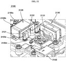
- the conversion unit 2020 may comprise a primary coil 2021 and a secondary coil 2022 disposed apart from the primary coil 2021 .
- a current supplied from an external power supply device flows through the primary coil 2021 , and the secondary coil 2022 may interact electromagnetically with the primary coil 2021 to output the converted current.
- the primary coil 2021 may be electrically connected to the first and the second case terminals 2010a and 2010b and may be supplied with a current from an external power supply device.
- the secondary coil 2022 may be electrically connected to the third, the fourth, and the fifth case terminals 2010c , 2010d , and 2010e.
- the third case terminal 2010c and the fourth case terminal 2010d may be electrically connected to the diode module.
- the secondary coil 2022 can be electrically connected to the diode module.
- the fifth case terminal 2010e may be electrically connected to the inductor unit 2030 .
- the secondary coil 2122, the first and the second terminals 2123 and 2124 , the inductor coil 2131 , the third terminal 2132 , and the bus bar 2140 may be integrally fabricated by casting. That is, among the "coil module," the secondary coil 2122 , the first and the second terminals 2123 and 2124 , the inductor coil 2131 , the third terminal 2132 , and the bus bar 2140 can be integrally formed.
- bolt-coupling for connecting the inductor coil 2131 and the bus bar 2140 can be omitted (as a result, the fifth case terminal 2010e of the comparative embodiment for bolt-coupling also can be omitted).
- bolt-coupling since bolt-coupling is not necessary, there is no gap that can be occurred by bolt-coupling. As a result, the problem of the bolt-coupling described above does not occur, and the conversion efficiency of the DC-DC converter 2100 can be increased.
- the second terminal 2124-1 may be extended from the secondary coil 2122-1 .
- the second terminal 2124-1 may be a member for electrically connecting the secondary coil 2122-1 and the inductor coil 2131-1 .
- the second terminal 2124-1 may be a plate-shaped conducting member.
- the second terminal 2124-1 may be a shape extended from the above towards the lower side (vertical direction), and then extended in the horizontal direction.
- One end of the second terminal 2124-1 may be curved or bent and extended in the vertical direction at the end portion of the secondary coil 2122-1 .
- the middle portion of the second terminal 2124-1 may be a shape downwardly extended.
- the other end of the second terminal 2124-1 may be in the shape of a plate bent or curved in a horizontal direction at the middle portion of the second terminal 2124-1 .
- the second board 3030 may be electrically connected to the first board 3020.
- the second board 3030 may be electrically connected to the first board 3020 by a connecting member 3040 .
- the second board 3030 may be disposed spaced apart from the coil unit 3050 which will be described later. In this case, the coil unit 3050 can penetrate the first board 3020. Since the coil unit 3050 is supported on the cooling plate 3012 and the first board 3020 is upwardly disposed spaced apart from the cooling plate 3012, a hole may be formed in the first board 3020 at the portion where the first board 3020 and the coil unit 3050 are overlapped with each other so that the coil unit 3050 can penetrate therethrough. (Refer to Figure 16 )
- the first board of the modified embodiment of the third embodiment may comprise an insulating layer 3023 and a pattern layer 3024.
- the first board may be a shape wherein an insulating layer 3023 and a pattern layer 3024 are sequentially stacked.
- the first board may be composed of only the insulating layer 3023 and the pattern layer 3024 .
Landscapes
- Engineering & Computer Science (AREA)
- Microelectronics & Electronic Packaging (AREA)
- Power Engineering (AREA)
- Physics & Mathematics (AREA)
- Thermal Sciences (AREA)
- Manufacturing & Machinery (AREA)
- Dc-Dc Converters (AREA)
- Cooling Or The Like Of Electrical Apparatus (AREA)
- Cooling Or The Like Of Semiconductors Or Solid State Devices (AREA)
Applications Claiming Priority (6)
| Application Number | Priority Date | Filing Date | Title |
|---|---|---|---|
| KR20160153088 | 2016-11-17 | ||
| KR20160180862 | 2016-12-28 | ||
| KR1020170148773A KR102458279B1 (ko) | 2017-11-09 | 2017-11-09 | Dc-dc 컨버터 |
| KR1020170152770A KR102417581B1 (ko) | 2016-11-17 | 2017-11-16 | Dc-dc 컨버터 |
| KR1020170152771A KR102536990B1 (ko) | 2016-12-28 | 2017-11-16 | Dc-dc 컨버터 |
| PCT/KR2017/013090 WO2018093195A1 (fr) | 2016-11-17 | 2017-11-17 | Convertisseur continu-continu |
Publications (3)
| Publication Number | Publication Date |
|---|---|
| EP3544396A1 true EP3544396A1 (fr) | 2019-09-25 |
| EP3544396A4 EP3544396A4 (fr) | 2020-08-05 |
| EP3544396B1 EP3544396B1 (fr) | 2022-09-14 |
Family
ID=67023425
Family Applications (1)
| Application Number | Title | Priority Date | Filing Date |
|---|---|---|---|
| EP17870977.0A Active EP3544396B1 (fr) | 2016-11-17 | 2017-11-17 | Convertisseur continu-continu |
Country Status (4)
| Country | Link |
|---|---|
| US (2) | US11251694B2 (fr) |
| EP (1) | EP3544396B1 (fr) |
| JP (2) | JP7055800B2 (fr) |
| CN (2) | CN109964548B (fr) |
Families Citing this family (14)
| Publication number | Priority date | Publication date | Assignee | Title |
|---|---|---|---|---|
| KR20180016102A (ko) * | 2016-08-05 | 2018-02-14 | 엘지이노텍 주식회사 | 전자 부품 패키지 |
| WO2018110890A1 (fr) * | 2016-12-14 | 2018-06-21 | 엘지이노텍 주식회사 | Boîtier de composant électronique et convertisseur cc-cc le comprenant |
| JP6758264B2 (ja) * | 2017-08-10 | 2020-09-23 | 株式会社デンソー | リアクトル冷却構造 |
| JP1640671S (fr) * | 2018-10-22 | 2019-09-09 | ||
| JP1635460S (fr) * | 2018-10-22 | 2019-07-01 | ||
| JP1635061S (fr) * | 2018-10-22 | 2019-07-01 | ||
| JP1635459S (fr) * | 2018-10-22 | 2019-07-01 | ||
| JP1635458S (fr) * | 2018-10-22 | 2019-07-01 | ||
| JP1654200S (fr) * | 2019-06-18 | 2020-03-02 | ||
| FR3100671A1 (fr) * | 2019-09-06 | 2021-03-12 | Valeo Siemens Eautomotive France Sas | Couvercle en plastique de fermeture d’un circuit de refroidissement à fluide, pour un équipement électrique |
| DE102019134565A1 (de) * | 2019-12-16 | 2021-06-17 | HELLA GmbH & Co. KGaA | Gehäuse für einen Stromrichter und Stromrichter, insbesondere Gleichstromsteller mit einem solchen Gehäuse |
| DE102020106404A1 (de) | 2020-03-10 | 2021-09-16 | Schaeffler Technologies AG & Co. KG | Kühlbare elektronische Baueinheit und elektromotorische Antriebseinrichtung |
| JP7405025B2 (ja) * | 2020-07-01 | 2023-12-26 | 株式会社デンソー | 電気製品 |
| KR20220072036A (ko) * | 2020-11-23 | 2022-06-02 | 현대모비스 주식회사 | 변압기의 ac 손실 최소화를 위한 버스바 및 그 설계방법 |
Family Cites Families (42)
| Publication number | Priority date | Publication date | Assignee | Title |
|---|---|---|---|---|
| CN1211802A (zh) | 1997-09-18 | 1999-03-24 | 朱柏 | 具有阻尼线圈的超导限流装置 |
| JP3567799B2 (ja) | 1999-06-15 | 2004-09-22 | トヨタ自動車株式会社 | 電気自動車用インバータの冷却装置 |
| JP3893860B2 (ja) * | 2000-08-11 | 2007-03-14 | 株式会社豊田自動織機 | 電子部品のケース及びその製造方法 |
| JP2002314280A (ja) * | 2001-04-10 | 2002-10-25 | Denki Kagaku Kogyo Kk | 回路基板の冷却構造及び冷却方法 |
| JP2003234589A (ja) | 2002-02-12 | 2003-08-22 | Toyota Industries Corp | 冷却装置 |
| DE10317580B4 (de) | 2002-04-18 | 2010-09-16 | Hitachi, Ltd. | Elektrische Wechselrichtervorrichtung mit einem Flüssigkeitskanal sowie Elektrofahrzeug mit einer derartigen Wechselrichtervorrichtung |
| KR200400294Y1 (ko) * | 2005-08-24 | 2005-11-04 | 주식회사 아시아 | 정션박스용 인쇄회로기판 연결장치 |
| JP5094045B2 (ja) | 2005-11-09 | 2012-12-12 | 大成プラス株式会社 | 冷却機能を有する電子回路装置とその製造方法 |
| JP4857017B2 (ja) | 2006-04-27 | 2012-01-18 | 日立オートモティブシステムズ株式会社 | 電力変換装置 |
| TW200731301A (fr) * | 2006-08-04 | 2007-08-16 | ||
| JP2008092653A (ja) * | 2006-09-30 | 2008-04-17 | Nippon Chemicon Corp | Dc−dcコンバータ |
| JP4494384B2 (ja) * | 2006-10-10 | 2010-06-30 | 新東ホールディングス株式会社 | ハイブリッドic回路 |
| JP4935499B2 (ja) | 2007-05-18 | 2012-05-23 | サンケン電気株式会社 | 直流変換装置 |
| JP2010011671A (ja) | 2008-06-30 | 2010-01-14 | Hitachi Ltd | 電力変換装置 |
| CN101754581B (zh) * | 2008-12-03 | 2012-03-21 | 倚天资讯股份有限公司 | 电子元件及陶瓷天线与应用其的电子装置 |
| KR100959866B1 (ko) | 2009-07-20 | 2010-05-27 | 삼성전기주식회사 | 패키지 기판용 리드핀 |
| JP5099086B2 (ja) | 2009-07-28 | 2012-12-12 | 株式会社デンソー | 電源装置 |
| CN201539727U (zh) * | 2009-09-19 | 2010-08-04 | 刘民生 | 电子节能灯 |
| JP2011129708A (ja) * | 2009-12-17 | 2011-06-30 | Panasonic Electric Works Co Ltd | プリント配線板の接続構造 |
| JP5471567B2 (ja) | 2010-02-17 | 2014-04-16 | 株式会社デンソー | 電力変換装置 |
| CN101937765B (zh) * | 2010-04-26 | 2012-11-21 | 广东风华高新科技股份有限公司 | 一种电感器的制作方法 |
| JP2011233726A (ja) | 2010-04-28 | 2011-11-17 | Kojima Press Industry Co Ltd | 電子部品冷却ケース |
| JP5655575B2 (ja) * | 2011-01-10 | 2015-01-21 | トヨタ自動車株式会社 | 冷却器及びそれを用いた電力変換装置 |
| CN102647884B (zh) | 2011-02-17 | 2015-03-18 | 北汽福田汽车股份有限公司 | 散热器及其散热水道系统结构 |
| KR101181248B1 (ko) * | 2011-07-22 | 2012-09-11 | 한국과학기술원 | 자기 보호 특성을 갖는 적외선 볼로미터 |
| CN202175679U (zh) * | 2011-08-24 | 2012-03-28 | 张星昊 | 磁光复合菌种诱变仪 |
| JP2012033955A (ja) * | 2011-10-13 | 2012-02-16 | Tamura Seisakusho Co Ltd | コイル及びコイルの成形方法 |
| KR101367071B1 (ko) | 2011-12-12 | 2014-02-25 | 삼성전기주식회사 | 히트 싱크 |
| JP5867074B2 (ja) | 2011-12-28 | 2016-02-24 | Tdk株式会社 | 電源ユニット、及び、電源装置の冷却装置 |
| WO2013118222A1 (fr) | 2012-02-07 | 2013-08-15 | 富士電機株式会社 | Dispositif de conversion de courant électrique |
| JP5926651B2 (ja) | 2012-08-24 | 2016-05-25 | 日立オートモティブシステムズ株式会社 | Dc−dcコンバータ装置および電力変換装置 |
| JP5738817B2 (ja) | 2012-09-14 | 2015-06-24 | 日立オートモティブシステムズ株式会社 | 電力変換装置 |
| JP2014075488A (ja) * | 2012-10-04 | 2014-04-24 | Toyota Industries Corp | 放熱装置 |
| CN103594430B (zh) | 2013-10-25 | 2017-01-18 | 上海交通大学 | 用于功率电子器件散热的微通道散热器 |
| US9859250B2 (en) * | 2013-12-20 | 2018-01-02 | Cyntec Co., Ltd. | Substrate and the method to fabricate thereof |
| US10297339B2 (en) * | 2014-02-19 | 2019-05-21 | Advantest Corporation | Integrated cooling system for electronics testing apparatus |
| US10085523B2 (en) * | 2014-08-11 | 2018-10-02 | Apple Inc. | Attachment system for an electronic device |
| CN204170915U (zh) * | 2014-09-12 | 2015-02-25 | 广东工业大学 | 超声辅助压制一体成型电感的装置 |
| CN204628931U (zh) | 2015-04-30 | 2015-09-09 | 江苏瑞腾涂装科技有限公司 | 一种冷却管道 |
| KR102458066B1 (ko) | 2015-11-09 | 2022-10-24 | 엘지이노텍 주식회사 | 냉각패널 및 이를 포함하는 전자 부품 패키지 |
| CN105578849B (zh) * | 2016-03-11 | 2019-02-15 | 中国科学院光电研究院 | 一种密封式散热装置及其制造方法 |
| CN206789405U (zh) * | 2017-06-13 | 2017-12-22 | 深圳市科达嘉电子有限公司 | 一种大电流一体成型电感器 |
-
2017
- 2017-11-17 EP EP17870977.0A patent/EP3544396B1/fr active Active
- 2017-11-17 JP JP2019521115A patent/JP7055800B2/ja active Active
- 2017-11-17 CN CN201780070562.5A patent/CN109964548B/zh active Active
- 2017-11-17 CN CN202110908075.XA patent/CN113645776B/zh active Active
- 2017-11-17 US US16/343,963 patent/US11251694B2/en active Active
-
2022
- 2022-01-14 US US17/575,992 patent/US11575313B2/en active Active
- 2022-04-06 JP JP2022063229A patent/JP2022095814A/ja active Pending
Also Published As
| Publication number | Publication date |
|---|---|
| US11251694B2 (en) | 2022-02-15 |
| JP2020507294A (ja) | 2020-03-05 |
| JP7055800B2 (ja) | 2022-04-18 |
| CN109964548B (zh) | 2021-08-27 |
| CN113645776A (zh) | 2021-11-12 |
| US11575313B2 (en) | 2023-02-07 |
| US20220247305A1 (en) | 2022-08-04 |
| EP3544396B1 (fr) | 2022-09-14 |
| JP2022095814A (ja) | 2022-06-28 |
| EP3544396A4 (fr) | 2020-08-05 |
| CN109964548A (zh) | 2019-07-02 |
| US20190252971A1 (en) | 2019-08-15 |
| CN113645776B (zh) | 2024-02-13 |
Similar Documents
| Publication | Publication Date | Title |
|---|---|---|
| US11575313B2 (en) | DC-DC converter | |
| CN202502877U (zh) | 变压器 | |
| KR102512381B1 (ko) | Dc-dc 컨버터 | |
| CN101840765B (zh) | 线圈部件、变压器以及开关电源装置 | |
| CN105449987A (zh) | 电源装置 | |
| CN105706196A (zh) | 电磁感应设备 | |
| CN110521100A (zh) | 电力转换装置用滤波器模块 | |
| KR102653471B1 (ko) | Dc-dc 컨버터 | |
| US9647535B2 (en) | Compact structure of power-supply apparatus capable of minimizing electromagnetic noise | |
| EP4006928B1 (fr) | Transformateur planaire et adaptateur de courant de commutation | |
| JP4300717B2 (ja) | Dc−dcコンバータ及びその製造方法 | |
| JP4218205B2 (ja) | 二バッテリ搭載型車両用降圧型dc−dcコンバータ装置 | |
| KR102536990B1 (ko) | Dc-dc 컨버터 | |
| CN213780903U (zh) | 一种集成电源模块的芯片及板卡 | |
| CN112400208A (zh) | 变压器 | |
| JP2001314080A (ja) | 降圧型電力用dc−dcコンバータ及び電子回路装置 | |
| JP6906874B2 (ja) | 電力変換装置 | |
| JP2021170879A (ja) | バスバーモジュール及びそれを用いた電力変換装置 | |
| CN219696214U (zh) | 一种变压器及电感的集成结构 | |
| CN216721173U (zh) | 高密度电源 | |
| CN117439403B (zh) | 一种电动汽车快速直流充电用的全桥llc谐振转换器 | |
| EP3905867A1 (fr) | Dispositif de conversion de puissance | |
| CN116110681A (zh) | 变压器、功率转换装置、变压器产品组以及变压器的制造方法 | |
| CN110690035A (zh) | 一种具备承受大电流和散热效果的变压器结构 | |
| CN115379722A (zh) | 水冷式无线能量拾取装置 |
Legal Events
| Date | Code | Title | Description |
|---|---|---|---|
| STAA | Information on the status of an ep patent application or granted ep patent |
Free format text: STATUS: THE INTERNATIONAL PUBLICATION HAS BEEN MADE |
|
| PUAI | Public reference made under article 153(3) epc to a published international application that has entered the european phase |
Free format text: ORIGINAL CODE: 0009012 |
|
| STAA | Information on the status of an ep patent application or granted ep patent |
Free format text: STATUS: REQUEST FOR EXAMINATION WAS MADE |
|
| 17P | Request for examination filed |
Effective date: 20190509 |
|
| AK | Designated contracting states |
Kind code of ref document: A1 Designated state(s): AL AT BE BG CH CY CZ DE DK EE ES FI FR GB GR HR HU IE IS IT LI LT LU LV MC MK MT NL NO PL PT RO RS SE SI SK SM TR |
|
| AX | Request for extension of the european patent |
Extension state: BA ME |
|
| DAV | Request for validation of the european patent (deleted) | ||
| DAX | Request for extension of the european patent (deleted) | ||
| A4 | Supplementary search report drawn up and despatched |
Effective date: 20200708 |
|
| RIC1 | Information provided on ipc code assigned before grant |
Ipc: H05K 7/20 20060101ALI20200702BHEP Ipc: H05K 7/02 20060101ALI20200702BHEP Ipc: H05K 1/02 20060101ALI20200702BHEP Ipc: H01F 27/28 20060101ALI20200702BHEP Ipc: H05K 7/14 20060101ALI20200702BHEP Ipc: H05K 5/00 20060101AFI20200702BHEP Ipc: H01F 41/04 20060101ALI20200702BHEP |
|
| GRAP | Despatch of communication of intention to grant a patent |
Free format text: ORIGINAL CODE: EPIDOSNIGR1 |
|
| STAA | Information on the status of an ep patent application or granted ep patent |
Free format text: STATUS: GRANT OF PATENT IS INTENDED |
|
| INTG | Intention to grant announced |
Effective date: 20220401 |
|
| GRAS | Grant fee paid |
Free format text: ORIGINAL CODE: EPIDOSNIGR3 |
|
| GRAA | (expected) grant |
Free format text: ORIGINAL CODE: 0009210 |
|
| STAA | Information on the status of an ep patent application or granted ep patent |
Free format text: STATUS: THE PATENT HAS BEEN GRANTED |
|
| AK | Designated contracting states |
Kind code of ref document: B1 Designated state(s): AL AT BE BG CH CY CZ DE DK EE ES FI FR GB GR HR HU IE IS IT LI LT LU LV MC MK MT NL NO PL PT RO RS SE SI SK SM TR |
|
| REG | Reference to a national code |
Ref country code: GB Ref legal event code: FG4D |
|
| REG | Reference to a national code |
Ref country code: CH Ref legal event code: EP |
|
| REG | Reference to a national code |
Ref country code: DE Ref legal event code: R096 Ref document number: 602017061876 Country of ref document: DE |
|
| REG | Reference to a national code |
Ref country code: IE Ref legal event code: FG4D |
|
| REG | Reference to a national code |
Ref country code: AT Ref legal event code: REF Ref document number: 1519487 Country of ref document: AT Kind code of ref document: T Effective date: 20221015 |
|
| REG | Reference to a national code |
Ref country code: NL Ref legal event code: FP |
|
| REG | Reference to a national code |
Ref country code: LT Ref legal event code: MG9D |
|
| PG25 | Lapsed in a contracting state [announced via postgrant information from national office to epo] |
Ref country code: SE Free format text: LAPSE BECAUSE OF FAILURE TO SUBMIT A TRANSLATION OF THE DESCRIPTION OR TO PAY THE FEE WITHIN THE PRESCRIBED TIME-LIMIT Effective date: 20220914 Ref country code: RS Free format text: LAPSE BECAUSE OF FAILURE TO SUBMIT A TRANSLATION OF THE DESCRIPTION OR TO PAY THE FEE WITHIN THE PRESCRIBED TIME-LIMIT Effective date: 20220914 Ref country code: NO Free format text: LAPSE BECAUSE OF FAILURE TO SUBMIT A TRANSLATION OF THE DESCRIPTION OR TO PAY THE FEE WITHIN THE PRESCRIBED TIME-LIMIT Effective date: 20221214 Ref country code: LV Free format text: LAPSE BECAUSE OF FAILURE TO SUBMIT A TRANSLATION OF THE DESCRIPTION OR TO PAY THE FEE WITHIN THE PRESCRIBED TIME-LIMIT Effective date: 20220914 Ref country code: LT Free format text: LAPSE BECAUSE OF FAILURE TO SUBMIT A TRANSLATION OF THE DESCRIPTION OR TO PAY THE FEE WITHIN THE PRESCRIBED TIME-LIMIT Effective date: 20220914 Ref country code: FI Free format text: LAPSE BECAUSE OF FAILURE TO SUBMIT A TRANSLATION OF THE DESCRIPTION OR TO PAY THE FEE WITHIN THE PRESCRIBED TIME-LIMIT Effective date: 20220914 |
|
| REG | Reference to a national code |
Ref country code: AT Ref legal event code: MK05 Ref document number: 1519487 Country of ref document: AT Kind code of ref document: T Effective date: 20220914 |
|
| PG25 | Lapsed in a contracting state [announced via postgrant information from national office to epo] |
Ref country code: HR Free format text: LAPSE BECAUSE OF FAILURE TO SUBMIT A TRANSLATION OF THE DESCRIPTION OR TO PAY THE FEE WITHIN THE PRESCRIBED TIME-LIMIT Effective date: 20220914 Ref country code: GR Free format text: LAPSE BECAUSE OF FAILURE TO SUBMIT A TRANSLATION OF THE DESCRIPTION OR TO PAY THE FEE WITHIN THE PRESCRIBED TIME-LIMIT Effective date: 20221215 |
|
| PG25 | Lapsed in a contracting state [announced via postgrant information from national office to epo] |
Ref country code: SM Free format text: LAPSE BECAUSE OF FAILURE TO SUBMIT A TRANSLATION OF THE DESCRIPTION OR TO PAY THE FEE WITHIN THE PRESCRIBED TIME-LIMIT Effective date: 20220914 Ref country code: RO Free format text: LAPSE BECAUSE OF FAILURE TO SUBMIT A TRANSLATION OF THE DESCRIPTION OR TO PAY THE FEE WITHIN THE PRESCRIBED TIME-LIMIT Effective date: 20220914 Ref country code: PT Free format text: LAPSE BECAUSE OF FAILURE TO SUBMIT A TRANSLATION OF THE DESCRIPTION OR TO PAY THE FEE WITHIN THE PRESCRIBED TIME-LIMIT Effective date: 20230116 Ref country code: ES Free format text: LAPSE BECAUSE OF FAILURE TO SUBMIT A TRANSLATION OF THE DESCRIPTION OR TO PAY THE FEE WITHIN THE PRESCRIBED TIME-LIMIT Effective date: 20220914 Ref country code: CZ Free format text: LAPSE BECAUSE OF FAILURE TO SUBMIT A TRANSLATION OF THE DESCRIPTION OR TO PAY THE FEE WITHIN THE PRESCRIBED TIME-LIMIT Effective date: 20220914 Ref country code: AT Free format text: LAPSE BECAUSE OF FAILURE TO SUBMIT A TRANSLATION OF THE DESCRIPTION OR TO PAY THE FEE WITHIN THE PRESCRIBED TIME-LIMIT Effective date: 20220914 |
|
| PG25 | Lapsed in a contracting state [announced via postgrant information from national office to epo] |
Ref country code: SK Free format text: LAPSE BECAUSE OF FAILURE TO SUBMIT A TRANSLATION OF THE DESCRIPTION OR TO PAY THE FEE WITHIN THE PRESCRIBED TIME-LIMIT Effective date: 20220914 Ref country code: PL Free format text: LAPSE BECAUSE OF FAILURE TO SUBMIT A TRANSLATION OF THE DESCRIPTION OR TO PAY THE FEE WITHIN THE PRESCRIBED TIME-LIMIT Effective date: 20220914 Ref country code: IS Free format text: LAPSE BECAUSE OF FAILURE TO SUBMIT A TRANSLATION OF THE DESCRIPTION OR TO PAY THE FEE WITHIN THE PRESCRIBED TIME-LIMIT Effective date: 20230114 Ref country code: EE Free format text: LAPSE BECAUSE OF FAILURE TO SUBMIT A TRANSLATION OF THE DESCRIPTION OR TO PAY THE FEE WITHIN THE PRESCRIBED TIME-LIMIT Effective date: 20220914 |
|
| REG | Reference to a national code |
Ref country code: DE Ref legal event code: R097 Ref document number: 602017061876 Country of ref document: DE |
|
| PG25 | Lapsed in a contracting state [announced via postgrant information from national office to epo] |
Ref country code: MC Free format text: LAPSE BECAUSE OF FAILURE TO SUBMIT A TRANSLATION OF THE DESCRIPTION OR TO PAY THE FEE WITHIN THE PRESCRIBED TIME-LIMIT Effective date: 20220914 Ref country code: AL Free format text: LAPSE BECAUSE OF FAILURE TO SUBMIT A TRANSLATION OF THE DESCRIPTION OR TO PAY THE FEE WITHIN THE PRESCRIBED TIME-LIMIT Effective date: 20220914 |
|
| REG | Reference to a national code |
Ref country code: CH Ref legal event code: PL |
|
| PLBE | No opposition filed within time limit |
Free format text: ORIGINAL CODE: 0009261 |
|
| STAA | Information on the status of an ep patent application or granted ep patent |
Free format text: STATUS: NO OPPOSITION FILED WITHIN TIME LIMIT |
|
| REG | Reference to a national code |
Ref country code: BE Ref legal event code: MM Effective date: 20221130 |
|
| PG25 | Lapsed in a contracting state [announced via postgrant information from national office to epo] |
Ref country code: LI Free format text: LAPSE BECAUSE OF NON-PAYMENT OF DUE FEES Effective date: 20221130 Ref country code: DK Free format text: LAPSE BECAUSE OF FAILURE TO SUBMIT A TRANSLATION OF THE DESCRIPTION OR TO PAY THE FEE WITHIN THE PRESCRIBED TIME-LIMIT Effective date: 20220914 Ref country code: CH Free format text: LAPSE BECAUSE OF NON-PAYMENT OF DUE FEES Effective date: 20221130 |
|
| 26N | No opposition filed |
Effective date: 20230615 |
|
| PG25 | Lapsed in a contracting state [announced via postgrant information from national office to epo] |
Ref country code: SI Free format text: LAPSE BECAUSE OF FAILURE TO SUBMIT A TRANSLATION OF THE DESCRIPTION OR TO PAY THE FEE WITHIN THE PRESCRIBED TIME-LIMIT Effective date: 20220914 Ref country code: LU Free format text: LAPSE BECAUSE OF NON-PAYMENT OF DUE FEES Effective date: 20221117 |
|
| PG25 | Lapsed in a contracting state [announced via postgrant information from national office to epo] |
Ref country code: IE Free format text: LAPSE BECAUSE OF NON-PAYMENT OF DUE FEES Effective date: 20221117 |
|
| PG25 | Lapsed in a contracting state [announced via postgrant information from national office to epo] |
Ref country code: BE Free format text: LAPSE BECAUSE OF NON-PAYMENT OF DUE FEES Effective date: 20221130 |
|
| PGFP | Annual fee paid to national office [announced via postgrant information from national office to epo] |
Ref country code: NL Payment date: 20231024 Year of fee payment: 7 |
|
| PGFP | Annual fee paid to national office [announced via postgrant information from national office to epo] |
Ref country code: GB Payment date: 20231023 Year of fee payment: 7 |
|
| PGFP | Annual fee paid to national office [announced via postgrant information from national office to epo] |
Ref country code: FR Payment date: 20231024 Year of fee payment: 7 Ref country code: DE Payment date: 20231023 Year of fee payment: 7 |
|
| PG25 | Lapsed in a contracting state [announced via postgrant information from national office to epo] |
Ref country code: HU Free format text: LAPSE BECAUSE OF FAILURE TO SUBMIT A TRANSLATION OF THE DESCRIPTION OR TO PAY THE FEE WITHIN THE PRESCRIBED TIME-LIMIT; INVALID AB INITIO Effective date: 20171117 |
|
| PG25 | Lapsed in a contracting state [announced via postgrant information from national office to epo] |
Ref country code: CY Free format text: LAPSE BECAUSE OF FAILURE TO SUBMIT A TRANSLATION OF THE DESCRIPTION OR TO PAY THE FEE WITHIN THE PRESCRIBED TIME-LIMIT Effective date: 20220914 |