EP3543013A1 - Bahndruckmaschine - Google Patents
Bahndruckmaschine Download PDFInfo
- Publication number
- EP3543013A1 EP3543013A1 EP18163065.8A EP18163065A EP3543013A1 EP 3543013 A1 EP3543013 A1 EP 3543013A1 EP 18163065 A EP18163065 A EP 18163065A EP 3543013 A1 EP3543013 A1 EP 3543013A1
- Authority
- EP
- European Patent Office
- Prior art keywords
- web
- printing machine
- shell
- machine according
- roller
- Prior art date
- Legal status (The legal status is an assumption and is not a legal conclusion. Google has not performed a legal analysis and makes no representation as to the accuracy of the status listed.)
- Granted
Links
Images



Classifications
-
- B—PERFORMING OPERATIONS; TRANSPORTING
- B41—PRINTING; LINING MACHINES; TYPEWRITERS; STAMPS
- B41F—PRINTING MACHINES OR PRESSES
- B41F13/00—Common details of rotary presses or machines
- B41F13/02—Conveying or guiding webs through presses or machines
-
- B—PERFORMING OPERATIONS; TRANSPORTING
- B41—PRINTING; LINING MACHINES; TYPEWRITERS; STAMPS
- B41J—TYPEWRITERS; SELECTIVE PRINTING MECHANISMS, i.e. MECHANISMS PRINTING OTHERWISE THAN FROM A FORME; CORRECTION OF TYPOGRAPHICAL ERRORS
- B41J11/00—Devices or arrangements of selective printing mechanisms, e.g. ink-jet printers or thermal printers, for supporting or handling copy material in sheet or web form
- B41J11/0015—Devices or arrangements of selective printing mechanisms, e.g. ink-jet printers or thermal printers, for supporting or handling copy material in sheet or web form for treating before, during or after printing or for uniform coating or laminating the copy material before or after printing
-
- B—PERFORMING OPERATIONS; TRANSPORTING
- B41—PRINTING; LINING MACHINES; TYPEWRITERS; STAMPS
- B41J—TYPEWRITERS; SELECTIVE PRINTING MECHANISMS, i.e. MECHANISMS PRINTING OTHERWISE THAN FROM A FORME; CORRECTION OF TYPOGRAPHICAL ERRORS
- B41J11/00—Devices or arrangements of selective printing mechanisms, e.g. ink-jet printers or thermal printers, for supporting or handling copy material in sheet or web form
- B41J11/0015—Devices or arrangements of selective printing mechanisms, e.g. ink-jet printers or thermal printers, for supporting or handling copy material in sheet or web form for treating before, during or after printing or for uniform coating or laminating the copy material before or after printing
- B41J11/002—Curing or drying the ink on the copy materials, e.g. by heating or irradiating
-
- B—PERFORMING OPERATIONS; TRANSPORTING
- B41—PRINTING; LINING MACHINES; TYPEWRITERS; STAMPS
- B41J—TYPEWRITERS; SELECTIVE PRINTING MECHANISMS, i.e. MECHANISMS PRINTING OTHERWISE THAN FROM A FORME; CORRECTION OF TYPOGRAPHICAL ERRORS
- B41J11/00—Devices or arrangements of selective printing mechanisms, e.g. ink-jet printers or thermal printers, for supporting or handling copy material in sheet or web form
- B41J11/02—Platens
- B41J11/04—Roller platens
-
- B—PERFORMING OPERATIONS; TRANSPORTING
- B41—PRINTING; LINING MACHINES; TYPEWRITERS; STAMPS
- B41J—TYPEWRITERS; SELECTIVE PRINTING MECHANISMS, i.e. MECHANISMS PRINTING OTHERWISE THAN FROM A FORME; CORRECTION OF TYPOGRAPHICAL ERRORS
- B41J15/00—Devices or arrangements of selective printing mechanisms, e.g. ink-jet printers or thermal printers, specially adapted for supporting or handling copy material in continuous form, e.g. webs
-
- B—PERFORMING OPERATIONS; TRANSPORTING
- B41—PRINTING; LINING MACHINES; TYPEWRITERS; STAMPS
- B41J—TYPEWRITERS; SELECTIVE PRINTING MECHANISMS, i.e. MECHANISMS PRINTING OTHERWISE THAN FROM A FORME; CORRECTION OF TYPOGRAPHICAL ERRORS
- B41J15/00—Devices or arrangements of selective printing mechanisms, e.g. ink-jet printers or thermal printers, specially adapted for supporting or handling copy material in continuous form, e.g. webs
- B41J15/005—Forming loops or sags in webs, e.g. for slackening a web or for compensating variations of the amount of conveyed web material (by arranging a "dancing roller" in a sag of the web material)
-
- B—PERFORMING OPERATIONS; TRANSPORTING
- B41—PRINTING; LINING MACHINES; TYPEWRITERS; STAMPS
- B41J—TYPEWRITERS; SELECTIVE PRINTING MECHANISMS, i.e. MECHANISMS PRINTING OTHERWISE THAN FROM A FORME; CORRECTION OF TYPOGRAPHICAL ERRORS
- B41J15/00—Devices or arrangements of selective printing mechanisms, e.g. ink-jet printers or thermal printers, specially adapted for supporting or handling copy material in continuous form, e.g. webs
- B41J15/02—Web rolls or spindles; Attaching webs to cores or spindles
-
- B—PERFORMING OPERATIONS; TRANSPORTING
- B41—PRINTING; LINING MACHINES; TYPEWRITERS; STAMPS
- B41J—TYPEWRITERS; SELECTIVE PRINTING MECHANISMS, i.e. MECHANISMS PRINTING OTHERWISE THAN FROM A FORME; CORRECTION OF TYPOGRAPHICAL ERRORS
- B41J15/00—Devices or arrangements of selective printing mechanisms, e.g. ink-jet printers or thermal printers, specially adapted for supporting or handling copy material in continuous form, e.g. webs
- B41J15/04—Supporting, feeding, or guiding devices; Mountings for web rolls or spindles
-
- B—PERFORMING OPERATIONS; TRANSPORTING
- B41—PRINTING; LINING MACHINES; TYPEWRITERS; STAMPS
- B41J—TYPEWRITERS; SELECTIVE PRINTING MECHANISMS, i.e. MECHANISMS PRINTING OTHERWISE THAN FROM A FORME; CORRECTION OF TYPOGRAPHICAL ERRORS
- B41J2/00—Typewriters or selective printing mechanisms characterised by the printing or marking process for which they are designed
- B41J2/005—Typewriters or selective printing mechanisms characterised by the printing or marking process for which they are designed characterised by bringing liquid or particles selectively into contact with a printing material
- B41J2/01—Ink jet
- B41J2/21—Ink jet for multi-colour printing
-
- B—PERFORMING OPERATIONS; TRANSPORTING
- B65—CONVEYING; PACKING; STORING; HANDLING THIN OR FILAMENTARY MATERIAL
- B65H—HANDLING THIN OR FILAMENTARY MATERIAL, e.g. SHEETS, WEBS, CABLES
- B65H23/00—Registering, tensioning, smoothing or guiding webs
- B65H23/04—Registering, tensioning, smoothing or guiding webs longitudinally
- B65H23/24—Registering, tensioning, smoothing or guiding webs longitudinally by fluid action, e.g. to retard the running web
-
- B—PERFORMING OPERATIONS; TRANSPORTING
- B65—CONVEYING; PACKING; STORING; HANDLING THIN OR FILAMENTARY MATERIAL
- B65H—HANDLING THIN OR FILAMENTARY MATERIAL, e.g. SHEETS, WEBS, CABLES
- B65H2301/00—Handling processes for sheets or webs
- B65H2301/30—Orientation, displacement, position of the handled material
- B65H2301/31—Features of transport path
- B65H2301/311—Features of transport path for transport path in plane of handled material, e.g. geometry
- B65H2301/31122—Omega-shaped
-
- B—PERFORMING OPERATIONS; TRANSPORTING
- B65—CONVEYING; PACKING; STORING; HANDLING THIN OR FILAMENTARY MATERIAL
- B65H—HANDLING THIN OR FILAMENTARY MATERIAL, e.g. SHEETS, WEBS, CABLES
- B65H2801/00—Application field
- B65H2801/03—Image reproduction devices
- B65H2801/15—Digital printing machines
Definitions
- the present invention relates to a printing machine for printing a web comprising a first roll and a second roll, between which the web forms a loop.
- a device for the supply of a printing material to the internal transport path of a printing module of a printing device in which a buffer device is provided for receiving the printing material, which has a buffer container having at the bottom of a vacuum device which generates a pressure acting on the substrate in the buffer vacuum ,
- the object of the invention is to provide a printing machine in which the web is gently guided.
- a printing machine for printing on a web comprising a first roll and a second roll, between which the web forms a loop, characterized in that between the first roll and the second roll a shell for pneumatic and the predominant length of curvature the shell is arranged equidistant guiding the sling.
- the printing press may be a digital printing press, preferably for inkjet printing.
- the shell may be simple or one-dimensionally curved, wherein the curvature may be in a circular arc shape.
- the shell may have only suction openings or only blowing openings for guiding the loop.
- the shell may have suction openings and blowing openings for non-contact guiding of the loop.
- the suction openings and blowing openings may be active at the same time to keep the web at a defined distance from the shell.
- the suction openings may be grooves which run in the transport or running direction of the web or obliquely thereto.
- the grooves may preferably be parallel to one another or diverge in the direction of travel, e.g. to tighten the web in the transverse direction.
- the blowing openings can form rows of nozzles that are arranged in alternation with the suction openings.
- the nozzle rows may e.g. consist of bores which eject the blast air in the radial direction with respect to the nozzle surface of the shell.
- the shell can be arranged on the outside of the loop and on the inside of the loop, a support roller can be arranged, which stands out of contact with the web during trouble-free printing operation.
- the strength of the suction air of the suction openings and the blowing air of the blowing openings can be balanced so that the web is floating without contact with the shell and the support roller between the two.
- the support roll need only support the web if the suction air of the shell is not active, e.g. in case of failure or shutdown of the vacuum generator to which the shell is connected, e.g. shutdown when threading the web or other setup process.
- An inner peripheral surface of the shell and an outer peripheral surface of the support roller may be parallel to each other.
- the shell and support roller can define between them a semi-annular gap through which the web runs without contact during printing operation.
- a format adjustment device for adjusting the suction openings to the respective width of the web may be present.
- the same format setting device or an additional format setting device can be used.
- Each format adjuster may be a valve with gate valve.
- the blowing openings may be throttling nozzles in which the air flow is throttled through a filter cartridge or a channel labyrinth.
- the filter insert can Foam piece sitting in the nozzle bore.
- the channel labyrinth may be a perforated plate labyrinth that forms a channel for connecting the blow holes to a blower air generator.
- the first roller and / or the second roller may be a cooling roller for cooling the web, wherein the cooling roller is traversed by a cooling fluid.
- each chill roll may be integrated into a circuit through which the cooling fluid is circulated by a pump.
- the first roll, the second roll and the shell may be disposed along a transport path of the web between a drying or pinning device and at least one subsequent inkjet printhead.
- the web guide to which the two rolls and the shell belong may be after a primer or primer coating device, e.g. for opaque white, and before a multicolor inkjet printing device, e.g. with four or more pressure bars, be arranged.
- FIGS. 1 to 3 are mutually corresponding components and elements designated by the same reference numerals.
- FIG. 1 shows a digital printing machine through which a web B of substrate runs in a direction indicated by arrow R direction.
- a primer or primer is applied to the web B with a coater 10 formed as an inkjet printhead.
- the applied primer or primer is dried with a pinning device 8.
- a printed image is printed on the primer or the primer with one or more inkjet printheads 9.
- a first roller 1 and a second roller 2 are arranged and between the two rollers 1, 2, a shell 3 and support roller 6 are arranged.
- the web B forms a loop or loop S between the two rolls 1, 2.
- the shell 3 is located on the same side of the web B as the rolls 1, 2, namely the back of the web B not coated by the coating device 10 the opposite side, namely the coated by the coating device 10 front side of the web B, there is the support roller. 6
- the shell 3 ensures in the printing operation that the loop S is stable, so that the web B wraps around the rollers 1, 2 each over a maximized circumferential angle.
- the area of contact between the web B and the roll 1 or 2 is large and the heat transfer from the web B to the respective roll 1 or 2 is also correspondingly large.
- the web B is undesirably heated, which is an unavoidable side effect. This heating of the web B would be detrimental to the print quality when printing the web B with the inkjet print head 9, if no countermeasure is taken. Without countermeasure, longitudinal folds would occur in the web B which would be visible in the print image of the inkjet print head 9.
- the countermeasure consists in cooling the web B by means of one or preferably both rollers 1, 2, for which purpose they are designed as cooling rollers.
- the rollers 1, 2 are traversed by a coolant, such as cooling water, and cause a lowering of the temperature of the web B to a value at which the longitudinal folds do not occur and the subsequent inkjet pressure is not impaired.
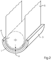
- FIG. 2 shows that the shell 3 has a curvature length L, which in the present case of the ideal circular arc-shaped shell 3 is a circular arc length.
- L curvature length
- This distance a is constant along almost the entire curvature length L. Only in the two end portions of the curvature length L, namely the inlet region and outlet region of the web B, the distance a due to pneumatic peculiarities in these end portions differently, eg smaller than in the intermediate main portion of the curvature length L.
- FIG. 3 shows the shell 3 as a single part in an unwound representation with a view of the nozzle surface of the shell 3, which faces the web B.
- the one-dimensionally curved guide surface or nozzle surface of the shell 3 has the geometric axis of rotation of the support roller 6 as the center of curvature.
- the inner circumferential surface or guide surface of the shell 3 thus extends concentrically with the outer peripheral surface of the support roller 6 - cf.
- FIG. 2 shows the shell 3 as a single part in an unwound representation with a view of the nozzle surface of the shell 3, which faces the web B.
- the one-dimensionally curved guide surface or nozzle surface of the shell 3 has the geometric axis of rotation of the support roller 6 as the center of curvature.
- the inner circumferential surface or guide surface of the shell 3 thus extends concentrically with the outer peripheral surface of the support roller 6 - cf.
- blow holes are introduced.
- the suction openings 4 are connected via a format setting device 7 to a vacuum generator, not shown, and the blowing openings 5 are connected via the Formateinstell issued 7 to a compressed air source, not shown.
- the blowing openings 5 are designed as throttle nozzles and arranged in rows which run parallel to the running direction R of the web B.
- the suction openings 4 are formed as grooves, which also extend parallel to the running direction R. Seen transversely to the running direction R, the suction openings 4 are arranged alternately with the blowing openings 5.
- FIG. 3 shown pattern can run between two suction grooves and a plurality of throttle nozzle rows and / or can run between two throttle nozzle rows and a plurality of suction grooves.
- the web B may contact and conform to the support roller 6 during a malfunction in printing operation or during a foreseen or unforeseen print interruption. If the web B continues to run during the fault or interruption of printing, the web B can drive the support roller 6 wrapped around it by peripheral surface friction. The support roller 6 can in this case run along with the web B without self-propulsion.
- FIG. 4 shows a modification which differs from the example in FIG. 3 only differs in that the grooves (suction openings 4) and the rows of throttle nozzles (Blasö réelleen 5) obliquely at a preferably acute angle relative to the direction R of the web B.
Landscapes
- Engineering & Computer Science (AREA)
- Mechanical Engineering (AREA)
- Ink Jet (AREA)
- Supply, Installation And Extraction Of Printed Sheets Or Plates (AREA)
- Handling Of Continuous Sheets Of Paper (AREA)
- Advancing Webs (AREA)
- Handling Of Sheets (AREA)
Abstract
Description
- Vorliegende Erfindung betrifft eine Druckmaschine zum Bedrucken einer Bahn, die eine erste Rolle und eine zweite Rolle umfasst, zwischen denen die Bahn eine Schlinge bildet.
- In
DE 10 2007 034 246 B4 ist eine Einrichtung für die Zufuhr einer Bedruckstoffbahn zum internen Transportweg eines Druckmoduls einer Druckeinrichtung beschrieben, bei der eine Puffervorrichtung zur Aufnahme der Bedruckstoffbahn vorgesehen ist, die einen Pufferbehälter aufweist, der am Boden eine Unterdruckvorrichtung aufweist, die im Pufferbehälter einen auf die Bedruckstoffbahn einwirkenden Unterdruck erzeugt. - Aufgabe der Erfindung ist, eine Druckmaschine zu schaffen, bei der die Bahn schonend geführt wird.
- Die Aufgabe wird gelöst durch eine Druckmaschine zum Bedrucken einer Bahn, umfassend eine erste Rolle und eine zweite Rolle, zwischen denen die Bahn eine Schlinge bildet, dadurch gekennzeichnet, dass zwischen der ersten Rolle und der zweiten Rolle eine Schale zum pneumatischen und bezüglich der überwiegenden Krümmungslänge der Schale äquidistanten Führen der Schlinge angeordnet ist.
- Es sind verschiedene Weiterbildungen möglich:
Die Druckmaschine kann eine Digitaldruckmaschine sein, vorzugsweise für Inkjetdruck. Die Schale kann einfach oder eindimensional gekrümmt sein, wobei die Krümmung in Kreisbogenform verlaufen kann. Die Schale kann nur Saugöffnungen oder nur Blasöffnungen zum Führen der Schlinge haben. - Die Schale kann Saugöffnungen und Blasöffnungen zum kontaktlosen Führen der Schlinge haben. Die Saugöffnungen und Blasöffnungen können gleichzeitig aktiv sein, um die Bahn in definiertem Abstand zur Schale zu halten.
- Die Saugöffnungen können Nuten sein, die in Transport- oder Laufrichtung der Bahn oder dazu schräg verlaufen. Die Nuten können vorzugsweise miteinander parallel verlaufen oder in Laufrichtung voneinander divergieren, z.B. um die Bahn in Querrichtung zu straffen.
- Die Blasöffnungen können Düsenreihen bilden, die im Wechsel mit den Saugöffnungen angeordnet sind. Die Düsenreihen können z.B. aus Bohrungen bestehen, die bezüglich der Düsenfläche der Schale die Blasluft in Radialrichtung ausstoßen.
- Die Schale kann auf der Außenseite der Schlinge angeordnet sein und auf der Innenseite der Schlinge kann eine Stützrolle angeordnet sein, die im störungsfrei laufenden Druckbetrieb außer Kontakt mit der Bahn steht. Die Stärke der Saugluft der Saugöffnungen und der Blasluft der Blasöffnungen können so ausbalanciert sein, dass die Bahn ohne Kontakt mit der Schale und der Stützrolle zwischen beiden schwebend läuft. Die Stützrolle braucht die Bahn nur zu stützen, wenn die Saugluft der Schale nicht aktiv ist, z.B. bei einem Ausfall oder einer Abschaltung des Vakuumerzeugers, an den die Schale angeschlossen ist, z.B. einer Abschaltung beim Einfädeln der Bahn oder einem anderen Rüstprozess.
- Eine Innenumfangsfläche der Schale und eine Außenumfangsfläche der Stützrolle können miteinander parallel verlaufen. Die Schale und Stützrolle können zwischen sich einen halbringförmigen Spalt begrenzen, durch den im Druckbetrieb die Bahn kontaktlos läuft.
- Eine Formateinstelleinrichtung zum Einstellen der Saugöffnungen auf die jeweilige Breite der Bahn kann vorhanden sein. Zum Einstellen der Blasöffnungen auf die jeweilige Breite der Bahn kann dieselbe Formateinstelleinrichtung oder eine zusätzliche Formateinstelleinrichtung verwendet werden. Jede Formateinstelleinrichtung kann ein Ventil mit Sperrschieber sein.
- Die Blasöffnungen können Drosseldüsen sein, bei denen der Luftstrom durch einen Filtereinsatz oder ein Kanallabyrinth gedrosselt wird. Der Filtereinsatz kann ein Schaumstoffstück sein, das in der Düsenbohrung sitzt. Das Kanallabyrinth kann ein Lochplattenlabyrinth sein, das einen Kanal zum Anschluss der Blasöffnungen an einen Blaslufterzeuger bildet.
- Die erste Rolle und/oder die zweite Rolle kann eine Kühlwalze zum Kühlen der Bahn sein, wobei die Kühlwalze von einem Kühlfluid durchströmt ist. Hierbei kann jede Kühlwalze in einen Kreislauf integriert sein, durch den das Kühlfluid mit einer Pumpe zirkuliert wird.
- Die erste Rolle, die zweite Rolle und die Schale können entlang eines Transportpfads der Bahn zwischen einer Trocknungs- oder Pinning-Einrichtung und mindestens einem nachfolgenden Inkjet-Druckkopf angeordnet sein. Die Bahnführung, zu der die beiden Rollen und die Schale gehören, kann nach einer Grundierungs- oder Primer-Beschichtungseinrichtung, z.B. für Deckweiß, und vor einer Einrichtung für den mehrfarbigen Inkjet-Druck, z.B. mit vier oder mehr Druckbalken, angeordnet sein.
- Weiterbildungen ergeben sich auch aus der folgenden Beschreibung eines Ausführungsbeispiels und der zugehörigen Zeichnung, worin zeigt:
- Figur 1:
- eine Digitaldruckmaschine mit einer Schale zum Führen einer Bedruckstoffbahn in schematischer Darstellung,
- Figur 2:
- die Führungsschale zusammen mit einer Stützrolle in räumlicher Darstellung,
- Figur 3:
- eine Draufsicht auf eine Düsenfläche der Führungsschale und
- Figur 4:
- eine Modifikation der Düsenfläche.
- In den
Figuren 1 bis 3 sind einander entsprechende Bauteile und Elemente mit den gleichen Bezugszeichen bezeichnet. -
Figur 1 zeigt eine Digitaldruckmaschine, durch die eine Bahn B aus Bedruckstoff in eine mit Pfeil angegebene Laufrichtung R läuft. Zuerst wird mit einer Beschichtungseinrichtung 10, die als Inkjet-Druckkopf ausgebildet ist, eine Grundierung oder ein Primer auf die Bahn B aufgebracht. Als nächstes wird mit einer Pinning-Einrichtung 8 die aufgebrachte Grundierung bzw. der aufgebrachte Primer getrocknet. Zuletzt wird mit einem oder mehreren Inkjet-Druckköpfen 9 ein Druckbild auf die Grundierung bzw. den Primer gedruckt. - Entlang der Bahn B zwischen der Pinning-Einrichtung 8 und dem Inkjet-Druckkopf 9 sind eine erste Rolle 1 und eine zweite Rolle 2 angeordnet und sind zwischen den beiden Rollen 1, 2 eine Schale 3 und Stützrolle 6 angeordnet. Zwischen den beiden Rollen 1, 2 bildet die Bahn B eine Schlaufe oder Schlinge S. Die Schale 3 befindet sich auf der gleichen Seite der Bahn B wie die Rollen 1, 2, nämlich der durch die Beschichtungseinrichtung 10 nicht beschichteten Rückseite der Bahn B. Auf der entgegengesetzten Seite, nämlich der durch die Beschichtungseinrichtung 10 beschichteten Vorderseite der Bahn B, befindet sich die Stützrolle 6.
- Die Schale 3 sorgt im Druckbetrieb dafür, dass die Schlinge S stabil ist, so dass die Bahn B die Rollen 1, 2 jeweils über einen maximierten Umfangswinkel hinweg umschlingt. Dadurch ist die Fläche des Kontaktes zwischen der Bahn B und der Rolle 1 bzw. 2 groß und ist die Wärmeübertragung von der Bahn B auf die jeweilige Rolle 1 bzw. 2 auch dementsprechend groß.
- Bei der Behandlung der Bahn B mit der Pinning-Einrichtung 8 wird die Bahn B in unerwünschter Weise erwärmt, was ein unvermeidlicher Nebeneffekt ist. Diese Erwärmung der Bahn B würde der Druckqualität beim Bedrucken der Bahn B mit dem Inkjet-Druckkopf 9 abträglich sein, wenn keine Gegenmaßnahme getroffen wird. Ohne Gegenmaßnahme würden in der Bahn B Längsfalten auftreten, die im Druckbild des Inkjet-Druckkopfs 9 sichtbar wären.
- Die Gegenmaßnahme besteht in einem Kühlen der Bahn B mittels einer der oder vorzugsweise beider Rollen 1, 2, wozu diese als Kühlrollen ausgebildet sind. Die Rollen 1, 2 werden von einem Kühlmittel, z.B. Kühlwasser, durchflossen und bewirken eine Absenkung der Temperatur der Bahn B auf einen Wert, bei dem die Längsfalten nicht auftreten und der nachfolgende Inkjet-Druck nicht beeinträchtigt ist.
-
Figur 2 zeigt, dass die Schale 3 eine Krümmungslänge L hat, die im vorliegenden Fall der ideal kreisbogenförmigen Schale 3 eine Kreisbogenlänge ist. Im störungsfreien Druckbetrieb besteht zwischen der laufenden Bahn B und der ihr zugewandten Düsenfläche der Schale 3 ein Spalt mit der Spaltweite oder dem Abstand a. Dieser Abstand a ist entlang der fast gesamten Krümmungslänge L konstant. Nur in den beiden Endabschnitten der Krümmungslänge L, nämlich dem Einlaufbereich und Auslaufbereich der Bahn B, kann der Abstand a aufgrund pneumatischer Besonderheiten in diesen Endabschnitten anders, z.B. kleiner, als im dazwischenliegenden Hauptabschnitt der Krümmungslänge L sein. -
Figur 3 zeigt die Schale 3 als Einzelteil in abgewickelter Darstellung mit Blick auf die Düsenfläche der Schale 3, welche der Bahn B zugewandt ist. Die eindimensional gekrümmte Führungsfläche oder Düsenfläche der Schale 3 hat als Krümmungsmittelpunkt die geometrische Rotationsachse der Stützrolle 6. Die Innenumfangsfläche oder Führungsfläche der Schale 3 verläuft also mit der Außenumfangsfläche der Stützrolle 6 konzentrisch - vgl.Figur 2 . - In die Führungsfläche bzw. Düsenfläche sind Saugöffnungen 4 und Blasöffnungen 5 eingebracht. Die Saugöffnungen 4 sind über eine Formateinstelleinrichtung 7 an einen nicht näher dargestellten Vakuumerzeuger angeschlossen und die Blasöffnungen 5 sind über die Formateinstelleinrichtung 7 an eine nicht näher dargestellte Druckluftquelle angeschlossen.
- Die Blasöffnungen 5 sind als Drosseldüsen ausgebildet und in Reihen angeordnet, die mit der Laufrichtung R der Bahn B parallel verlaufen. Die Saugöffnungen 4 sind als Nuten ausgebildet, welche ebenfalls mit der Laufrichtung R parallel verlaufen. Quer zur Laufrichtung R gesehen sind die Saugöffnungen 4 im Wechsel mit den Blasöffnungen 5 angeordnet.
- Abweichend von dem in
Figur 3 gezeigten Muster können zwischen jeweils zwei Saugnuten auch mehrere Drosseldüsenreihen verlaufen und/oder können zwischen jeweils zwei Drosseldüsenreihen auch mehrere Saugnuten verlaufen. - Mit der Formateinstelleinrichtung 7, welche nur schematisch angedeutet ist, können die außerhalb der Formatbreite der Bahn B liegenden und von dieser nicht überdeckten Saugöffnungen 4 und/oder Blasöffnungen 5 deaktiviert werden.
- Durch entsprechende Einstellungen des Vakuumerzeugers und der Druckluftquelle ist die Stärke des an den Saugöffnungen 4 anliegenden Vakuums und die Stärke der aus den Vakuumöffnungen 5 ausgestoßenen Blasluft zueinander so ausbalanciert, dass die durch die Saugöffnungen 4 angesaugte und dabei gleichzeitig durch die Blasöffnungen 5 auf einem Luftpolster getragene Bahn B ohne Kontakt mit der Schale 3 und ebenfalls ohne Kontakt mit der Stützrolle 6 zwischen beiden schwebend läuft, solange der Druckbetrieb störungsfrei ist.
- Die Bahn B kann die Stützrolle 6 kontaktieren und sich an diese anschmiegen, während einer Störung im Druckbetrieb oder während einer vorhergesehenen oder unvorhergesehenen Druckunterbrechung. Wenn die Bahn B während der Störung oder Druckunterbrechung weiterläuft, kann die Bahn B die von ihr umschlungene Stützrolle 6 über Umfangsflächenreibung antreiben. Die Stützrolle 6 kann hierbei ohne Eigenantrieb mit der Bahn B mitlaufen.
- Im störungsfreien Druckbetrieb ist sichergestellt, dass das durch die Pinning-Einrichtung 8 noch nicht vollständig getrocknete oder gehärtete Druckbild der Beschichtungseinrichtung 10 vor Beschädigungen geschützt ist, weil dieses Druckbild mit der Stützrolle 6 nicht in Kontakt kommt. Durch die die Bahn B berührungslos führende Schale 3 ist eine sehr schonende Bahnführung gewährleistet.
-
Figur 4 zeigt eine Modifikation, welche sich von dem Beispiel inFigur 3 nur dadurch unterscheidet, dass die Nuten (Saugöffnungen 4) und die Reihen der Drosseldüsen (Blasöffnungen 5) unter einem vorzugsweise spitzen Winkel relativ zur Laufrichtung R der Bahn B schräg verlaufen. -
- 1
- erste Rolle
- 2
- zweite Rolle
- 3
- Schale
- 4
- Saugöffnung
- 5
- Blasöffnung
- 6
- Stützrolle
- 7
- Formateinstelleinrichtung
- 8
- Pinning-Einrichtung
- 9
- Inkjet-Druckkopf
- 10
- Beschichtungseinrichtung
- a
- Abstand
- B
- Bahn
- L
- Krümmungslänge
- R
- Laufrichtung
- S
- Schlinge
Claims (10)
- Druckmaschine zum Bedrucken einer Bahn (B), umfassend eine erste Rolle (1) und eine zweite Rolle (2), zwischen denen die Bahn (B) eine Schlinge (S) bildet,
dadurch gekennzeichnet,
dass zwischen der ersten Rolle (1) und der zweiten Rolle (2) eine Schale (3) zum pneumatischen und bezüglich der überwiegenden Krümmungslänge (L) der Schale (3) äquidistanten Führen der Schlinge (S) angeordnet ist. - Druckmaschine nach Anspruch 1,
dadurch gekennzeichnet,
dass die Schale (3) Saugöffnungen (4) und Blasöffnungen (5) zum kontaktlosen Führen der Schlinge (S) hat. - Druckmaschine nach Anspruch 2,
dadurch gekennzeichnet,
dass die Saugöffnungen (4) Nuten sind, die entweder mit der Laufrichtung (R) der Bahn (B) parallel oder relativ zur Laufrichtung (R) schräg verlaufen. - Druckmaschine nach Anspruch 2 oder 3,
dadurch gekennzeichnet,
dass die Blasöffnungen (5) Düsenreihen bilden, die im Wechsel mit den Saugöffnungen (4) angeordnet sind. - Druckmaschine nach einem der Ansprüche 1 bis 4,
dadurch gekennzeichnet,
dass die Schale (3) auf der Außenseite der Schlinge (S) angeordnet ist und auf der Innenseite der Schlinge (S) eine Stützrolle (6) angeordnet ist, die im störungsfrei laufenden Druckbetrieb außer Kontakt mit der Bahn (B) steht. - Druckmaschine nach Anspruch 5,
dadurch gekennzeichnet,
dass eine Innenumfangsfläche der Schale (3) und eine Außenumfangsfläche der Stützrolle (6) miteinander parallel verlaufen. - Druckmaschine nach einem der Ansprüche 2 bis 6,
dadurch gekennzeichnet,
dass eine Formateinstelleinrichtung (7) zum Einstellen der Saugöffnungen (4) auf die jeweilige Breite der Bahn (B) vorhanden ist. - Druckmaschine nach einem der Ansprüche 2 bis 7,
dadurch gekennzeichnet,
dass die Blasöffnungen (5) Drosseldüsen sind, bei denen der Luftstrom durch einen Filtereinsatz oder ein Kanallabyrinth gedrosselt wird. - Druckmaschine nach einem der Ansprüche 1 bis 8,
dadurch gekennzeichnet,
dass die erste Rolle (1) und/oder die zweite Rolle (2) eine Kühlwalze zum Kühlen der Bahn (B) ist, wobei die Kühlwalze von einem Kühlfluid durchströmt ist. - Druckmaschine nach einem der Ansprüche 1 bis 9,
dadurch gekennzeichnet,
dass die erste Rolle (1), die zweite Rolle (2) und die Schale (3) entlang eines Transportpfads der Bahn (B) zwischen einer Trocknungs- oder Pinning-Einrichtung (8) und mindestens einem nachfolgenden Inkjet-Druckkopf (9) angeordnet ist.
Priority Applications (4)
| Application Number | Priority Date | Filing Date | Title |
|---|---|---|---|
| EP18163065.8A EP3543013B1 (de) | 2018-03-21 | 2018-03-21 | Bahndruckmaschine |
| CN201910187797.3A CN110293773B (zh) | 2018-03-21 | 2019-03-13 | 幅带印刷机 |
| JP2019052737A JP7222769B2 (ja) | 2018-03-21 | 2019-03-20 | ウェブ印刷機 |
| US16/360,241 US10717301B2 (en) | 2018-03-21 | 2019-03-21 | Web-fed printing machine |
Applications Claiming Priority (1)
| Application Number | Priority Date | Filing Date | Title |
|---|---|---|---|
| EP18163065.8A EP3543013B1 (de) | 2018-03-21 | 2018-03-21 | Bahndruckmaschine |
Publications (2)
| Publication Number | Publication Date |
|---|---|
| EP3543013A1 true EP3543013A1 (de) | 2019-09-25 |
| EP3543013B1 EP3543013B1 (de) | 2021-06-09 |
Family
ID=61731677
Family Applications (1)
| Application Number | Title | Priority Date | Filing Date |
|---|---|---|---|
| EP18163065.8A Active EP3543013B1 (de) | 2018-03-21 | 2018-03-21 | Bahndruckmaschine |
Country Status (4)
| Country | Link |
|---|---|
| US (1) | US10717301B2 (de) |
| EP (1) | EP3543013B1 (de) |
| JP (1) | JP7222769B2 (de) |
| CN (1) | CN110293773B (de) |
Families Citing this family (1)
| Publication number | Priority date | Publication date | Assignee | Title |
|---|---|---|---|---|
| CN116692551B (zh) * | 2022-02-28 | 2026-01-30 | 宁德时代新能源科技股份有限公司 | 料带转向机构、烘干装置和极片制造设备 |
Citations (4)
| Publication number | Priority date | Publication date | Assignee | Title |
|---|---|---|---|---|
| US3807612A (en) * | 1973-05-15 | 1974-04-30 | Fmc Corp | Web feeding apparatus for blank making machine |
| DE2365668A1 (de) * | 1973-08-27 | 1976-04-01 | Juergen Schulz | Vorrichtung fuer druckmaschinen zum bedrucken von bahnfoermigem material |
| DE10032675A1 (de) * | 2000-07-05 | 2002-01-24 | Aradex Ag | Bahnverarbeitende Maschine |
| DE102007034246B4 (de) | 2007-07-23 | 2010-10-28 | OCé PRINTING SYSTEMS GMBH | Einrichtung mit einer Vorzentriervorrichtung und einer Puffervorrichtung für die Zufuhr einer Bedruckstoffbahn zu einer Druckeinrichtung |
Family Cites Families (11)
| Publication number | Priority date | Publication date | Assignee | Title |
|---|---|---|---|---|
| US3061159A (en) * | 1958-09-15 | 1962-10-30 | A C T Inc | Air actuated self-energizing tensioning system |
| DE1951002C3 (de) * | 1969-10-09 | 1974-02-07 | Vits-Maschinenbau Gmbh, 4018 Langenfeld | Einrichtung zur berührungslosen Stabilisierung einer in ihrer Längsrichtung gespannten und bewegten Warenbahn |
| DD228795A1 (de) * | 1984-11-19 | 1985-10-23 | Polygraph Leipzig | Bogenleiteinrichtung im auslagetrommelbereich von druckmaschinen |
| JP2001301301A (ja) * | 2000-04-26 | 2001-10-31 | Riso Kagaku Corp | 孔版印刷装置 |
| JP2005305794A (ja) * | 2004-04-21 | 2005-11-04 | Komori Corp | シート状物の乾燥機 |
| JP4963683B2 (ja) * | 2008-03-31 | 2012-06-27 | 富士フイルム株式会社 | インクジェット記録装置 |
| JP5885335B2 (ja) * | 2012-01-06 | 2016-03-15 | 東レエンジニアリング株式会社 | エアダンサー |
| JP2014101159A (ja) * | 2012-11-16 | 2014-06-05 | Bellmatic Ltd | 搬送装置 |
| KR102023581B1 (ko) * | 2012-11-23 | 2019-09-24 | 해성디에스 주식회사 | 릴-투-릴 검사장치 및 릴-투-릴 검사방법 |
| CN103465621B (zh) * | 2013-09-11 | 2015-07-08 | 上海美声服饰辅料有限公司 | 一种气浮式丝网印刷品干燥系统和方法 |
| CN204894762U (zh) * | 2015-07-27 | 2015-12-23 | 天津中荣印刷科技有限公司 | 一种印刷机烘干装置 |
-
2018
- 2018-03-21 EP EP18163065.8A patent/EP3543013B1/de active Active
-
2019
- 2019-03-13 CN CN201910187797.3A patent/CN110293773B/zh active Active
- 2019-03-20 JP JP2019052737A patent/JP7222769B2/ja active Active
- 2019-03-21 US US16/360,241 patent/US10717301B2/en active Active
Patent Citations (4)
| Publication number | Priority date | Publication date | Assignee | Title |
|---|---|---|---|---|
| US3807612A (en) * | 1973-05-15 | 1974-04-30 | Fmc Corp | Web feeding apparatus for blank making machine |
| DE2365668A1 (de) * | 1973-08-27 | 1976-04-01 | Juergen Schulz | Vorrichtung fuer druckmaschinen zum bedrucken von bahnfoermigem material |
| DE10032675A1 (de) * | 2000-07-05 | 2002-01-24 | Aradex Ag | Bahnverarbeitende Maschine |
| DE102007034246B4 (de) | 2007-07-23 | 2010-10-28 | OCé PRINTING SYSTEMS GMBH | Einrichtung mit einer Vorzentriervorrichtung und einer Puffervorrichtung für die Zufuhr einer Bedruckstoffbahn zu einer Druckeinrichtung |
Also Published As
| Publication number | Publication date |
|---|---|
| JP2019167245A (ja) | 2019-10-03 |
| JP7222769B2 (ja) | 2023-02-15 |
| US10717301B2 (en) | 2020-07-21 |
| US20190291470A1 (en) | 2019-09-26 |
| CN110293773B (zh) | 2021-04-09 |
| EP3543013B1 (de) | 2021-06-09 |
| CN110293773A (zh) | 2019-10-01 |
Similar Documents
| Publication | Publication Date | Title |
|---|---|---|
| DE60011397T2 (de) | Blasgerät für eine papiermaschine oder dergleichen | |
| AT508470B1 (de) | Verfahren und vorrichtung zum übertragen einer faserbahn von einem stützgewebe zu einem anderen | |
| WO1983000514A1 (fr) | Groupe de cylindres de sechage | |
| DE3504820A1 (de) | Vorrichtung in der trockenpartie einer papiermaschine | |
| DE102004031171A1 (de) | Maschine zur Verarbeitung von Bogen | |
| DE3706542C2 (de) | ||
| EP0988417A1 (de) | Trockenpartie | |
| DE2458455A1 (de) | Vorrichtung zum trocknen einer sich bewegenden bahn | |
| DE69326761T2 (de) | Mehrzwecksblaskasten mit düsen | |
| WO2004101408A2 (de) | Bahnführungseinrichtung | |
| AT394870B (de) | Trocknungsvorrichtung | |
| EP3543013B1 (de) | Bahndruckmaschine | |
| DE4111911A1 (de) | Walze | |
| DE4317400C2 (de) | Vorrichtung zum Trocknen von bedruckten Materialbahnen | |
| DE60100491T2 (de) | Punktaufzeichnungsgerät | |
| DE4042168A1 (de) | Walze mit kraefteausuebenden bereichen | |
| AT413274B (de) | Bogenleiteinrichtung in einer rotationsdruckmaschine | |
| AT410949B (de) | Verfahren und vorrichtung in der trockenpartie von einer papier-/kartonmaschine | |
| DE102019213305A1 (de) | Bedruckstoff-Transportvorrichtung und Druckmaschine | |
| DE102019205295A1 (de) | Bedruckstofftransportvorrichtung | |
| AT506852B1 (de) | System in einer trockenpartie einer bahnbildungsmaschine zum führen eines siebs und des weiteren der bahn mit führungswalzen | |
| DE102012218049B4 (de) | Vorrichtung zum Wenden und Fördern von Bogen in Druckmaschinen | |
| DE202017102453U1 (de) | Anordnung bei der Bahnkontrolle auf der Trockenpartie der Faserbahnmaschine | |
| DE102009048004B3 (de) | Heiz- oder kühlbare Walze | |
| DE2615261A1 (de) | Vorrichtung zum behandeln von bahnfoermigem material |
Legal Events
| Date | Code | Title | Description |
|---|---|---|---|
| PUAI | Public reference made under article 153(3) epc to a published international application that has entered the european phase |
Free format text: ORIGINAL CODE: 0009012 |
|
| STAA | Information on the status of an ep patent application or granted ep patent |
Free format text: STATUS: THE APPLICATION HAS BEEN PUBLISHED |
|
| AK | Designated contracting states |
Kind code of ref document: A1 Designated state(s): AL AT BE BG CH CY CZ DE DK EE ES FI FR GB GR HR HU IE IS IT LI LT LU LV MC MK MT NL NO PL PT RO RS SE SI SK SM TR |
|
| AX | Request for extension of the european patent |
Extension state: BA ME |
|
| STAA | Information on the status of an ep patent application or granted ep patent |
Free format text: STATUS: REQUEST FOR EXAMINATION WAS MADE |
|
| 17P | Request for examination filed |
Effective date: 20200325 |
|
| RBV | Designated contracting states (corrected) |
Designated state(s): AL AT BE BG CH CY CZ DE DK EE ES FI FR GB GR HR HU IE IS IT LI LT LU LV MC MK MT NL NO PL PT RO RS SE SI SK SM TR |
|
| GRAP | Despatch of communication of intention to grant a patent |
Free format text: ORIGINAL CODE: EPIDOSNIGR1 |
|
| STAA | Information on the status of an ep patent application or granted ep patent |
Free format text: STATUS: GRANT OF PATENT IS INTENDED |
|
| INTG | Intention to grant announced |
Effective date: 20210309 |
|
| GRAS | Grant fee paid |
Free format text: ORIGINAL CODE: EPIDOSNIGR3 |
|
| GRAA | (expected) grant |
Free format text: ORIGINAL CODE: 0009210 |
|
| STAA | Information on the status of an ep patent application or granted ep patent |
Free format text: STATUS: THE PATENT HAS BEEN GRANTED |
|
| AK | Designated contracting states |
Kind code of ref document: B1 Designated state(s): AL AT BE BG CH CY CZ DE DK EE ES FI FR GB GR HR HU IE IS IT LI LT LU LV MC MK MT NL NO PL PT RO RS SE SI SK SM TR |
|
| REG | Reference to a national code |
Ref country code: GB Ref legal event code: FG4D Free format text: NOT ENGLISH |
|
| REG | Reference to a national code |
Ref country code: CH Ref legal event code: EP Ref country code: AT Ref legal event code: REF Ref document number: 1400131 Country of ref document: AT Kind code of ref document: T Effective date: 20210615 |
|
| REG | Reference to a national code |
Ref country code: DE Ref legal event code: R096 Ref document number: 502018005579 Country of ref document: DE |
|
| REG | Reference to a national code |
Ref country code: IE Ref legal event code: FG4D Free format text: LANGUAGE OF EP DOCUMENT: GERMAN |
|
| REG | Reference to a national code |
Ref country code: LT Ref legal event code: MG9D |
|
| PG25 | Lapsed in a contracting state [announced via postgrant information from national office to epo] |
Ref country code: HR Free format text: LAPSE BECAUSE OF FAILURE TO SUBMIT A TRANSLATION OF THE DESCRIPTION OR TO PAY THE FEE WITHIN THE PRESCRIBED TIME-LIMIT Effective date: 20210609 Ref country code: BG Free format text: LAPSE BECAUSE OF FAILURE TO SUBMIT A TRANSLATION OF THE DESCRIPTION OR TO PAY THE FEE WITHIN THE PRESCRIBED TIME-LIMIT Effective date: 20210909 Ref country code: FI Free format text: LAPSE BECAUSE OF FAILURE TO SUBMIT A TRANSLATION OF THE DESCRIPTION OR TO PAY THE FEE WITHIN THE PRESCRIBED TIME-LIMIT Effective date: 20210609 Ref country code: LT Free format text: LAPSE BECAUSE OF FAILURE TO SUBMIT A TRANSLATION OF THE DESCRIPTION OR TO PAY THE FEE WITHIN THE PRESCRIBED TIME-LIMIT Effective date: 20210609 |
|
| REG | Reference to a national code |
Ref country code: NL Ref legal event code: MP Effective date: 20210609 |
|
| PG25 | Lapsed in a contracting state [announced via postgrant information from national office to epo] |
Ref country code: RS Free format text: LAPSE BECAUSE OF FAILURE TO SUBMIT A TRANSLATION OF THE DESCRIPTION OR TO PAY THE FEE WITHIN THE PRESCRIBED TIME-LIMIT Effective date: 20210609 Ref country code: SE Free format text: LAPSE BECAUSE OF FAILURE TO SUBMIT A TRANSLATION OF THE DESCRIPTION OR TO PAY THE FEE WITHIN THE PRESCRIBED TIME-LIMIT Effective date: 20210609 Ref country code: LV Free format text: LAPSE BECAUSE OF FAILURE TO SUBMIT A TRANSLATION OF THE DESCRIPTION OR TO PAY THE FEE WITHIN THE PRESCRIBED TIME-LIMIT Effective date: 20210609 Ref country code: NO Free format text: LAPSE BECAUSE OF FAILURE TO SUBMIT A TRANSLATION OF THE DESCRIPTION OR TO PAY THE FEE WITHIN THE PRESCRIBED TIME-LIMIT Effective date: 20210909 Ref country code: GR Free format text: LAPSE BECAUSE OF FAILURE TO SUBMIT A TRANSLATION OF THE DESCRIPTION OR TO PAY THE FEE WITHIN THE PRESCRIBED TIME-LIMIT Effective date: 20210910 |
|
| PG25 | Lapsed in a contracting state [announced via postgrant information from national office to epo] |
Ref country code: EE Free format text: LAPSE BECAUSE OF FAILURE TO SUBMIT A TRANSLATION OF THE DESCRIPTION OR TO PAY THE FEE WITHIN THE PRESCRIBED TIME-LIMIT Effective date: 20210609 Ref country code: ES Free format text: LAPSE BECAUSE OF FAILURE TO SUBMIT A TRANSLATION OF THE DESCRIPTION OR TO PAY THE FEE WITHIN THE PRESCRIBED TIME-LIMIT Effective date: 20210609 Ref country code: SK Free format text: LAPSE BECAUSE OF FAILURE TO SUBMIT A TRANSLATION OF THE DESCRIPTION OR TO PAY THE FEE WITHIN THE PRESCRIBED TIME-LIMIT Effective date: 20210609 Ref country code: SM Free format text: LAPSE BECAUSE OF FAILURE TO SUBMIT A TRANSLATION OF THE DESCRIPTION OR TO PAY THE FEE WITHIN THE PRESCRIBED TIME-LIMIT Effective date: 20210609 Ref country code: RO Free format text: LAPSE BECAUSE OF FAILURE TO SUBMIT A TRANSLATION OF THE DESCRIPTION OR TO PAY THE FEE WITHIN THE PRESCRIBED TIME-LIMIT Effective date: 20210609 Ref country code: NL Free format text: LAPSE BECAUSE OF FAILURE TO SUBMIT A TRANSLATION OF THE DESCRIPTION OR TO PAY THE FEE WITHIN THE PRESCRIBED TIME-LIMIT Effective date: 20210609 Ref country code: PT Free format text: LAPSE BECAUSE OF FAILURE TO SUBMIT A TRANSLATION OF THE DESCRIPTION OR TO PAY THE FEE WITHIN THE PRESCRIBED TIME-LIMIT Effective date: 20211011 Ref country code: CZ Free format text: LAPSE BECAUSE OF FAILURE TO SUBMIT A TRANSLATION OF THE DESCRIPTION OR TO PAY THE FEE WITHIN THE PRESCRIBED TIME-LIMIT Effective date: 20210609 |
|
| PG25 | Lapsed in a contracting state [announced via postgrant information from national office to epo] |
Ref country code: PL Free format text: LAPSE BECAUSE OF FAILURE TO SUBMIT A TRANSLATION OF THE DESCRIPTION OR TO PAY THE FEE WITHIN THE PRESCRIBED TIME-LIMIT Effective date: 20210609 |
|
| REG | Reference to a national code |
Ref country code: DE Ref legal event code: R097 Ref document number: 502018005579 Country of ref document: DE |
|
| PLBE | No opposition filed within time limit |
Free format text: ORIGINAL CODE: 0009261 |
|
| STAA | Information on the status of an ep patent application or granted ep patent |
Free format text: STATUS: NO OPPOSITION FILED WITHIN TIME LIMIT |
|
| PG25 | Lapsed in a contracting state [announced via postgrant information from national office to epo] |
Ref country code: DK Free format text: LAPSE BECAUSE OF FAILURE TO SUBMIT A TRANSLATION OF THE DESCRIPTION OR TO PAY THE FEE WITHIN THE PRESCRIBED TIME-LIMIT Effective date: 20210609 |
|
| 26N | No opposition filed |
Effective date: 20220310 |
|
| PG25 | Lapsed in a contracting state [announced via postgrant information from national office to epo] |
Ref country code: AL Free format text: LAPSE BECAUSE OF FAILURE TO SUBMIT A TRANSLATION OF THE DESCRIPTION OR TO PAY THE FEE WITHIN THE PRESCRIBED TIME-LIMIT Effective date: 20210609 |
|
| PG25 | Lapsed in a contracting state [announced via postgrant information from national office to epo] |
Ref country code: IT Free format text: LAPSE BECAUSE OF FAILURE TO SUBMIT A TRANSLATION OF THE DESCRIPTION OR TO PAY THE FEE WITHIN THE PRESCRIBED TIME-LIMIT Effective date: 20210609 |
|
| PG25 | Lapsed in a contracting state [announced via postgrant information from national office to epo] |
Ref country code: MC Free format text: LAPSE BECAUSE OF FAILURE TO SUBMIT A TRANSLATION OF THE DESCRIPTION OR TO PAY THE FEE WITHIN THE PRESCRIBED TIME-LIMIT Effective date: 20210609 |
|
| REG | Reference to a national code |
Ref country code: CH Ref legal event code: PL |
|
| GBPC | Gb: european patent ceased through non-payment of renewal fee |
Effective date: 20220321 |
|
| REG | Reference to a national code |
Ref country code: BE Ref legal event code: MM Effective date: 20220331 |
|
| PG25 | Lapsed in a contracting state [announced via postgrant information from national office to epo] |
Ref country code: LU Free format text: LAPSE BECAUSE OF NON-PAYMENT OF DUE FEES Effective date: 20220321 Ref country code: LI Free format text: LAPSE BECAUSE OF NON-PAYMENT OF DUE FEES Effective date: 20220331 Ref country code: IE Free format text: LAPSE BECAUSE OF NON-PAYMENT OF DUE FEES Effective date: 20220321 Ref country code: GB Free format text: LAPSE BECAUSE OF NON-PAYMENT OF DUE FEES Effective date: 20220321 Ref country code: FR Free format text: LAPSE BECAUSE OF NON-PAYMENT OF DUE FEES Effective date: 20220331 Ref country code: CH Free format text: LAPSE BECAUSE OF NON-PAYMENT OF DUE FEES Effective date: 20220331 |
|
| PG25 | Lapsed in a contracting state [announced via postgrant information from national office to epo] |
Ref country code: BE Free format text: LAPSE BECAUSE OF NON-PAYMENT OF DUE FEES Effective date: 20220331 |
|
| P01 | Opt-out of the competence of the unified patent court (upc) registered |
Effective date: 20230427 |
|
| PG25 | Lapsed in a contracting state [announced via postgrant information from national office to epo] |
Ref country code: MK Free format text: LAPSE BECAUSE OF FAILURE TO SUBMIT A TRANSLATION OF THE DESCRIPTION OR TO PAY THE FEE WITHIN THE PRESCRIBED TIME-LIMIT Effective date: 20210609 Ref country code: CY Free format text: LAPSE BECAUSE OF FAILURE TO SUBMIT A TRANSLATION OF THE DESCRIPTION OR TO PAY THE FEE WITHIN THE PRESCRIBED TIME-LIMIT Effective date: 20210609 |
|
| REG | Reference to a national code |
Ref country code: AT Ref legal event code: MM01 Ref document number: 1400131 Country of ref document: AT Kind code of ref document: T Effective date: 20230321 |
|
| PG25 | Lapsed in a contracting state [announced via postgrant information from national office to epo] |
Ref country code: HU Free format text: LAPSE BECAUSE OF FAILURE TO SUBMIT A TRANSLATION OF THE DESCRIPTION OR TO PAY THE FEE WITHIN THE PRESCRIBED TIME-LIMIT; INVALID AB INITIO Effective date: 20180321 |
|
| PG25 | Lapsed in a contracting state [announced via postgrant information from national office to epo] |
Ref country code: TR Free format text: LAPSE BECAUSE OF FAILURE TO SUBMIT A TRANSLATION OF THE DESCRIPTION OR TO PAY THE FEE WITHIN THE PRESCRIBED TIME-LIMIT Effective date: 20210609 |
|
| PG25 | Lapsed in a contracting state [announced via postgrant information from national office to epo] |
Ref country code: AT Free format text: LAPSE BECAUSE OF NON-PAYMENT OF DUE FEES Effective date: 20230321 |
|
| PG25 | Lapsed in a contracting state [announced via postgrant information from national office to epo] |
Ref country code: AT Free format text: LAPSE BECAUSE OF NON-PAYMENT OF DUE FEES Effective date: 20230321 |
|
| PG25 | Lapsed in a contracting state [announced via postgrant information from national office to epo] |
Ref country code: MT Free format text: LAPSE BECAUSE OF FAILURE TO SUBMIT A TRANSLATION OF THE DESCRIPTION OR TO PAY THE FEE WITHIN THE PRESCRIBED TIME-LIMIT Effective date: 20210609 |
|
| PGFP | Annual fee paid to national office [announced via postgrant information from national office to epo] |
Ref country code: DE Payment date: 20250331 Year of fee payment: 8 |
|
| PGFP | Annual fee paid to national office [announced via postgrant information from national office to epo] |
Ref country code: AT Payment date: 20260410 Year of fee payment: 5 |