EP3540102A1 - Process for spinning and/or twisting yarns, machine for spinning and/or twisting yarns and method to transform a machine for spinning and/or twisting yarns - Google Patents
Process for spinning and/or twisting yarns, machine for spinning and/or twisting yarns and method to transform a machine for spinning and/or twisting yarns Download PDFInfo
- Publication number
- EP3540102A1 EP3540102A1 EP17723157.8A EP17723157A EP3540102A1 EP 3540102 A1 EP3540102 A1 EP 3540102A1 EP 17723157 A EP17723157 A EP 17723157A EP 3540102 A1 EP3540102 A1 EP 3540102A1
- Authority
- EP
- European Patent Office
- Prior art keywords
- yarn
- balloon
- twisting
- spinning
- picking
- Prior art date
- Legal status (The legal status is an assumption and is not a legal conclusion. Google has not performed a legal analysis and makes no representation as to the accuracy of the status listed.)
- Granted
Links
- 238000009987 spinning Methods 0.000 title claims abstract description 48
- 238000000034 method Methods 0.000 title claims abstract description 45
- 238000004804 winding Methods 0.000 claims description 8
- 241001589086 Bellapiscis medius Species 0.000 description 14
- 238000004519 manufacturing process Methods 0.000 description 3
- 230000000694 effects Effects 0.000 description 2
- 239000011152 fibreglass Substances 0.000 description 2
- OKTJSMMVPCPJKN-UHFFFAOYSA-N Carbon Chemical compound [C] OKTJSMMVPCPJKN-UHFFFAOYSA-N 0.000 description 1
- 229920003235 aromatic polyamide Polymers 0.000 description 1
- 239000012237 artificial material Substances 0.000 description 1
- 229910052799 carbon Inorganic materials 0.000 description 1
- 238000005265 energy consumption Methods 0.000 description 1
- 239000000835 fiber Substances 0.000 description 1
- 238000007378 ring spinning Methods 0.000 description 1
- 230000003068 static effect Effects 0.000 description 1
- 239000004753 textile Substances 0.000 description 1
Images


Classifications
-
- D—TEXTILES; PAPER
- D01—NATURAL OR MAN-MADE THREADS OR FIBRES; SPINNING
- D01H—SPINNING OR TWISTING
- D01H1/00—Spinning or twisting machines in which the product is wound-up continuously
- D01H1/14—Details
- D01H1/42—Guards or protectors for yarns or threads, e.g. separator plates, anti-ballooning devices
-
- D—TEXTILES; PAPER
- D01—NATURAL OR MAN-MADE THREADS OR FIBRES; SPINNING
- D01H—SPINNING OR TWISTING
- D01H1/00—Spinning or twisting machines in which the product is wound-up continuously
- D01H1/02—Spinning or twisting machines in which the product is wound-up continuously ring type
-
- D—TEXTILES; PAPER
- D01—NATURAL OR MAN-MADE THREADS OR FIBRES; SPINNING
- D01H—SPINNING OR TWISTING
- D01H7/00—Spinning or twisting arrangements
- D01H7/02—Spinning or twisting arrangements for imparting permanent twist
- D01H7/04—Spindles
- D01H7/18—Arrangements on spindles for suppressing yarn balloons
-
- B—PERFORMING OPERATIONS; TRANSPORTING
- B65—CONVEYING; PACKING; STORING; HANDLING THIN OR FILAMENTARY MATERIAL
- B65H—HANDLING THIN OR FILAMENTARY MATERIAL, e.g. SHEETS, WEBS, CABLES
- B65H57/00—Guides for filamentary materials; Supports therefor
- B65H57/22—Guides for filamentary materials; Supports therefor adapted to prevent excessive ballooning of material
-
- D—TEXTILES; PAPER
- D01—NATURAL OR MAN-MADE THREADS OR FIBRES; SPINNING
- D01H—SPINNING OR TWISTING
- D01H1/00—Spinning or twisting machines in which the product is wound-up continuously
- D01H1/14—Details
- D01H1/42—Guards or protectors for yarns or threads, e.g. separator plates, anti-ballooning devices
- D01H1/425—Anti-ballooning rings
-
- D—TEXTILES; PAPER
- D01—NATURAL OR MAN-MADE THREADS OR FIBRES; SPINNING
- D01H—SPINNING OR TWISTING
- D01H7/00—Spinning or twisting arrangements
- D01H7/02—Spinning or twisting arrangements for imparting permanent twist
- D01H7/86—Multiple-twist arrangements, e.g. two-for-one twisting devices ; Threading of yarn; Devices in hollow spindles for imparting false twist
-
- B—PERFORMING OPERATIONS; TRANSPORTING
- B65—CONVEYING; PACKING; STORING; HANDLING THIN OR FILAMENTARY MATERIAL
- B65H—HANDLING THIN OR FILAMENTARY MATERIAL, e.g. SHEETS, WEBS, CABLES
- B65H2701/00—Handled material; Storage means
- B65H2701/30—Handled filamentary material
- B65H2701/31—Textiles threads or artificial strands of filaments
-
- D—TEXTILES; PAPER
- D01—NATURAL OR MAN-MADE THREADS OR FIBRES; SPINNING
- D01H—SPINNING OR TWISTING
- D01H2700/00—Spinning or twisting machines; Drafting devices
- D01H2700/24—Spinning or twisting machines of different kinds
Definitions
- the height of the stretches of balloon is at least two times the height of the picking means.
- the yarn passing through a stretching means located at a point prior to the yarn picking and/or feeding means namely, in yarn ring spinning and ring twisting.
- the stress is also adjusted by other external means.
- the figure 3 shows a ring twister, which is specially suitable for processing fiberglass, in which the same common elements have the same numeral references the feeding means (1) being arranged on the top and the yarn picking (3) bobbin (2) at the bottom of the machine, therefore the direction of the yarn is downwards, as in the embodiments of machines shown in the figures 1 y 2 .
- the yarn feeding means (1) or the yarn picking means is located so that the exit of the yarn of the yarn feeding means (1) or the entrance of the yarn of the yarn picking means (2) is located approximately on the vertical axis (V) of the stretch of balloon.
- a third feature of the invention is a method to transform a yarn spinning and/or twisting machine characterized in that it includes a step in which the height of stretch of the balloon (LB) is increased so that, by operating the twisting means, a body of revolution is created from a diameter generating a balloon that has at least a hyperboloid structure (E) forming at least two stretches of balloon (B) consecutive to each other.
- LB height of stretch of the balloon
- E hyperboloid structure
- the increase of the stretch of balloon (LB) is achieved by lifting the yarn feeding means (1) and/or the yarn guiding means (8) with respect to the yarn picking means (2), or by lifting the yarn picking means (2) with respect to the yarn feeding means (1).
Landscapes
- Engineering & Computer Science (AREA)
- Mechanical Engineering (AREA)
- Textile Engineering (AREA)
- Spinning Or Twisting Of Yarns (AREA)
- Yarns And Mechanical Finishing Of Yarns Or Ropes (AREA)
Abstract
Description
- This application has as object the registration of a process for spinning and/or twisting yarns with multiple stretches of balloon, which process is designed to be carried out by means of a yarn twisting or spinning machine.
- More specifically, the invention proposes to develop a method for spinning and/or twisting yarns that allows working faster without it means increasing the stress of the yarn that occurs in the process of spinning and/or twisting, as well as a machine for spinning and/or twisting yarns using that method and a method to transform a machine for spinning and/or twisting yarns.
- In the textile industry, and namely in the spinning and twisting industry the use of continuous ring spinners, ring twisters, multiple twist twisters, double twist twisters, vertical wiring, cabling twister etc. is well-known.
- All these machines to provide twist to the yarn are obliged to rotate the yarn at a distance with respect to the centre of rotation with the purpose of saving a space occupied by a part of the machine and this generates a revolution figure named "balloon". This balloon is defined by an area or volume of revolution with a central spin axis, for example, with a conical volume.
- The trend of the manufacturers of spinning and twisting machines is to suppress or reduce the balloon by limiting it physically in order to avoid an increase of the diameter of the balloon and to reduce the height of the balloon as much as possible. This way, the stress generated in the yarn for the process of twisting and/or spinning are lower in order to avoid possible damages to the yarn, affecting its quality, breakages during the production process, therefore the rotation or angular speed is limited and has to be reduced, or in other words, it cannot be increased having therefore a negative effect on the productivity.
- This invention was developed in order to provide a method configured as a novelty within the field of application and it solves the above-mentioned drawbacks, providing in addition other further advantages that will be apparent from the description below.
- Therefore an object of this invention is to provide a process for spinning and/or twisting yarns having multiple stretches of balloon, in which a yarn runs between a yarn feeding means (such as for example at least a bobbin) towards a yarn picking means, this yarn picking and/or winding means connected to driving means to rotate the yarn picking means at a predetermined speed, in which a stretch of balloon is generated at a point located between the feeding means and the picking means because of the presence of twisting means. Namely, the invention is characterized in that the rotation speed value of the yarn twisting means is such that the path the yarn follows between the feeding means and the picking (or winding) means, by operating the twisting means, generates a helical path with oscillating spiral diameters along the distance existing between the feeding means and the yarn picking and/or winding means such that a revolution body is created that has at least a hyperboloid structure forming at least two stretches of balloon consecutive to each other.
- According to another feature of the invention, the process can be carried out by means of multiple hyperboloid structures defining a number of hyperboloids ranging from 2 to 20.
- In working conditions with determined parameters, the increase of the stretches of balloon, that in turn implies an increase of the hyperboloid structures, is achieved by increasing the height of the stretch of balloon and, therefore, to increase the diameter value of times generating the already established stretch of balloon , so that values of the height of the stretch of balloon are increased from 5 to 50 times the diameter generating a stretch of balloon as it is wished to increase the stretches of balloon, and therefore, increasing the hyperboloid structures that would pass from 2 to 20 as such height is being increased.
- That is why the twisting is produced by means of multiple stretches of balloon that offsets the stress of the work so that the stress produced by stressing means is lower than in the traditional spinning and/or twisting processes.
- Thanks to these characteristics, it is possible to produce yarn spinning and/or twisting at higher speed and therefore, with a higher rate of productivity, with a low stress of the yarn, and a lower energy consumption allowing to cut down the costs of production and upgrade the quality of the yarn.
- The stress that can be generated in the yarn by the effect of the rotation speed centrifugal forces, is counteracted in the inflection points between the stretches of balloon.
- Another advantage this method provides is that it allows twisting very thin yarns with a low level of stress, which extends to handling new very delicate yarns that currently are broken when working with stress they cannot absorb.
- This method is suitable for every yarn, fibre, filament, rope, ribbon, etc., as well as natural, synthetic and artificial materials. It can result especially suitable for handling fiberglass, carbon, aramid fibres, etc., because it allows to work at higher speed and with a lower level of stress.
- Preferably, the height of the stretches of balloon is at least two times the diameter generating the stretch of balloon.
- In an even more preferred embodiment, the height of the stretches of balloon ranges from 5 to 50, especially from 5 to 25 times the diameter generating the stretch of balloon.
- This range of height is preferably distributed so that for diameters generating, for example, 200mm or 216mm or 250mm or 300mm or 330mm or 400mm or 500mm, and depending on the thickness of the yarn to be processed 2 stretches of balloon can be obtained (i.e., a hyperboloid structure) with heights of 5 times the diameter generating the stretch of balloon, or as the thickness of the yarn increases, this height needs to be increased 6 times the diameter generating the stretch of balloon, or 7 times the diameter generating the stretch of balloon, even 8 times the diameter generating the stretch of balloon.
- On the other hand, if the generating diameter is being reduced to values, such as for example, 165mm, or 140mm or 120mm or 100mm down to 30mm, so that two stretches of balloon are obtained, the height is determined with a
relation 5 times the diameter generating the stretch of balloon, or six times the diameter generating the stretch of balloon, or even seven times the diameter generating the stretch of balloon such value evolving in different way than with large generating diameters. - In addition, preferably, the height of the stretches of balloon is at least two times the height of the picking means.
- In the same way, it can also be preferable that the height of the stretches of balloon is at least two times the height of the feeding means.
- According to another feature of the invention, the yarn passing through a stretching means located at a point prior to the yarn picking and/or feeding means, namely, in yarn ring spinning and ring twisting. In the case of double twisting, direct wiring and vertical machines, the stress is also adjusted by other external means.
- Preferably, the stretching means in ring spinner and ring twister includes a cursor that is coupled to a bobbin rail connected to the winding bobbin.
- A second feature of the invention is a yarn spinning and/or twisting machine, that includes:
- a yarn feeding means,
- a yarn picking means,
- twisting means located between the yarn feeding means and the yarn picking means that generate a diameter generating a stretch of balloon of yarn in an area generating a stretch of balloon,
- driving means connected to the yarn feeding and/or picking means, and
- It must be said that in the case of ring spinners and ring twisters, an increase of the number of the stretches of balloon is associated to a decrease of the sizes of the cursor and therefore of the weight of the cursor itself with the subsequent advantages that means.
- A third feature of the invention is a method to transform a yarn spinning and/or twisting machine characterized in that it includes a step in which the height of the stretch of balloon is increased either by lifting the yarn feeding means and/or guiding means with respect to the yarn picking means so that the path of the yarn, or lifting the yarn picking means with respect to the yarn feeding means.
- Consequently, to the increase of the height of the stretch of balloon and by operating the twisting means, a body of revolution is created from a diameter generating a balloon that has at least a hyperboloid structure forming at least two stretches of balloon consecutive to each other.
- Other characteristics and advantages of the method object of this invention shall be apparent from the description of a preferred but not exclusive embodiment that is illustrated as a non-limiting example in the drawings attached in which:
-
-
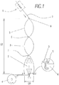
Figure 1 . - Is a schematized view of a first embodiment of a continuous ring spinner that uses the method according to this invention that includes a detailed view of the cursor; -
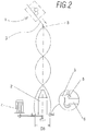
Figure 2 . - Is a schematized view of a second embodiment of a ring twister machine that uses the method of the invention that includes a detailed view of the cursor; -
Figure 3 . - Is a schematized view of a third embodiment of another ring twister machine that uses the method of the invention that includes a detailed view of the cursor; -
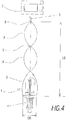
Figure 4 . - Is a schematized view of a fourth embodiment a double twist twister that uses the method of the invention; -
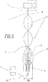
Figure 5 . - Is a schematized view of a fifth embodiment of a vertical wiring machine that uses the method of the invention; -
Figure 6 . - Is a schematized view of the geometrical shape the yarn adopts during the twisting process according to this invention; -
Figure 7 . - Is a schematized view of a path a yarn can take in a process according to this invention; and -
Figure 8 . - Is a schematized view showing a machine that uses means for stretching the yarn combined with a guiding means. -
Figure 9 . - Is a schematized view showing a ring twister without guiding means. -
Figure 10 . - Is a schematized view showing a machine that uses yarn-stretching means without a guiding means. -
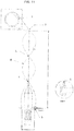
Figure 11 . - Is a schematized view of a ring twister that uses a roller as guiding means; - In view of the mentioned figures and in accordance with the numbering adopted, an example of preferred embodiment can be seen, that includes the parts and elements indicated and described in detail below.
- In all the preferred embodiments of the spinning and twisting machine described below, the value of the rotation speed of the winding bobbin is such that an helical path is generated, with an oscillating spire diameter (S), (see
figure 7 ) along the distance (LB) existing between the feeding means and the winding bobbin such that a body of revolution is created that has two consecutive hyperboloid structures (E) forming a plurality of stretches of balloon (B) consecutive to each other. - Another feature of the invention is, as it is shown in the
figure 1 , a ring spinner having on the top a yarn feeding system, indicated generally with reference (1) that is of a conventional type therefore it shall not be described in more details, while at the bottom a bobbin (2) is provided for picking the yarn (3) that rotates motor-driven by conventional driving means (4) shown schematized. The yarn (3) that is wound in the bobbin enters perpendicularly with respect to the bobbin side wall as the yarn is made to pass by a stretching element named cursor (5) placed in a bobbin rail (6) that picks the yarn that has been twisted and stores it in the bobbin (2). The said cursor (5) is best apparent in the enlarged detail included in thefigure 1 . - During the yarn winding process (3), in the embodiments shown herein, three stretches of balloon (B) are formed (the number of stretches of balloon being not limitative) between a yarn guiding means (8) (indicated schematized), as for example, a small-diameter ring and an area generating a stretch of balloon provoked by twisting means so that a stretch generating diameter (DB) is generated of the structure with multiple stretches of balloon of yarn, in which are defined two strangling of hyperboloid stretches (E) that allow to reduce the level of stress of the yarn. An essential characteristic of the machine is the nonexistence of elements limiting the balloon. It shall be understood by limiting the balloon any element that makes contact with the yarn in the stretch where the balloons are generated.
- It shall be mentioned that the distance (LB) existing between the guiding means and the area generating the stretch of balloon is at least two times the diameter generating the balloon (DB), so that at least two stretches of balloon are generated between the guiding means and the area generating a stretch of balloon.
- It has to be said that the number of stretches of balloon (B) can be increased or reduced (the minimum being two stretches of balloon) by increasing or reducing the distance (LB) existing between the yarn guiding element and the element responsible of provoking the twisting, in this case represented, the cursor (5).
- In a preferred embodiment, the height of the stretches of balloon is ranging from 5 to 50 times the diameter generating the stretch of balloon.
- In an even more preferred embodiment, the height of the stretches of balloon is ranging from 5 to 25 times the diameter generating the stretch of balloon.
- In a non-limitative example of embodiment, with a generating diameter (DB) of 36mm eight hyperboloid structures can be obtained (i.e., nine stretches of balloon) with a height of stretch of balloon equivalent to 50 times the generating diameter of 36mm for a yarn with a 30Nm titre.
- By "titre" is meant the relation existing between the weigh and the length of a yarn, the former being a fixed value and the later a variable value.
- The
figure 2 shows a ring twister with a yarn feeding roller from a static creel in which the same common elements have the same numeral references, the feeding means being generally indicated with the reference (1), arranged on the top and the yarn picking (3) bobbin (2) at the bottom of the machine. - The
figure 3 shows a ring twister, which is specially suitable for processing fiberglass, in which the same common elements have the same numeral references the feeding means (1) being arranged on the top and the yarn picking (3) bobbin (2) at the bottom of the machine, therefore the direction of the yarn is downwards, as in the embodiments of machines shown in thefigures 1 y 2 . - The
figure 4 shows a double twisting twister in which the same common elements have the same numeral references. - The
figure 5 shows a vertical wiring machine with two yarns in which the same common elements have the same numeral references, in which the direction of the operation is upwards the same as the machine shown in thefigure 4 and indicated by means of the arrow (f), i.e., the picking bobbin is arranged on the top while at the bottom there is the means feeding a first and second yarns that are interlocked to each other. In this machine, the yarn (3) and the additional yarn (H2) are joined, in which the additional yarn (H2) is supplied by a feeder (7). - The
figures 6 to 8 , show a geometrical profile that the yarn adopts during the twisting process, in which three stretches of balloon (figure 6 ) are formed as well as the actual path a yarn can carry out during the process of handling a yarn. - In a preferred embodiment, the yarn spinning and/or twisting machine is comprised of, means to increase or reduce the height of the stretch of balloon (LB) (no shown). This characteristic facilitates the access to the yarn feeding means (1) or to the yarn picking means (2) that during the operation of the machine are not easily accessible for the user as they are in a too high position. Thus, the means to increase or reduce the height of the stretch of balloon (LB) allow, when it is necessary, for example to replace a bobbin, reduce the height of the stretch of balloon in order that the user have an easy access to the yarn feeding means (1) or to the yarn picking means (2). After replacing the bobbin, the means to increase or reduce the height of the stretch of balloon (LB) allows that, the yarn feeding means (1) or the yarn picking means (2) come back to their operating position.
- In a preferred embodiment, the guiding means (8) for guiding the yarn (3) move in height associated to the movement in height of the bobbin rail (6) and cursor (5). The movement in height of the bobbin rail (6) and cursor (5) facilitates picking the yarn in the yarn picking means handled (3), such as a bobbin (2), that remains fixed in height. The movement of the guiding means (8) associated to the movement in height of the bobbin rail (6) and cursor (5) allows that the height of the stretches of balloon (LB) remains unchanged avoiding thus variations of the shape of the balloons. Optionally the yarn feeding means (1) move in height jointly with the guiding means (8)
- In a preferred embodiment (
figure 9 ) the yarn feeding means (1) or the yarn picking means is located so that the exit of the yarn of the yarn feeding means (1) or the entrance of the yarn of the yarn picking means (2) is located approximately on the vertical axis (V) of the stretch of balloon. - In a preferred embodiment of the guiding means (8) for guiding the yarn (3), especially when it is a delicate yarn, is a roller (9) (
figure 11 ). Optionally the roller (9) can have a forced rotatory movement associated to the rotatory movement of the yarn feeding means (1) in order to reduce the friction of the yarn that is generated when the yarn makes contract with the roller (9). - In a preferred embodiment, the yarn feeding means (1) is comprised of yarn stretching means (
figures 8 and10 ). Optionally the direction followed by the yarn within the yarn stretching means is at an angle ranging from -20º to +20º with relation to the vertical (V). In an even more preferred embodiment, the direction followed by the yarn within the yarn stretching means is coincident with the vertical (V). In any of the said cases, guiding means (figure 10 ) can be not required. - A third feature of the invention is a method to transform a yarn spinning and/or twisting machine characterized in that it includes a step in which the height of stretch of the balloon (LB) is increased so that, by operating the twisting means, a body of revolution is created from a diameter generating a balloon that has at least a hyperboloid structure (E) forming at least two stretches of balloon (B) consecutive to each other.
- The increase of the stretch of balloon (LB) is achieved by lifting the yarn feeding means (1) and/or the yarn guiding means (8) with respect to the yarn picking means (2), or by lifting the yarn picking means (2) with respect to the yarn feeding means (1).
- The details, shapes, sizes and the rest of accessory elements, used in the production of the method of the invention can be conveniently replaced by others that do not depart from the scope defined by the claims attached below.
Claims (22)
- Process for yarn spinning and/or twisting , in which a yarn runs between a yarn feeding means (1) towards a yarn picking means , the said yarn picking means been connected to driving means to rotate the yarn picking means at a predetermined speed , in which a spot of balloon is generated in a point located between the feeding means (1) and the picking means because of the presence of twisting means, characterized in that the value of the rotation speed of the yarn twisting means is such that an helical path is generated with oscillating spire diameters along the distance existing between the feeding means (1) and the yarn picking means, such that the path of the yarn, by operating the twisting means, creates a body of revolution from a diameter generating a balloon that has at least a hyperboloid structure (E) forming at least two spots of balloon (B) consecutive to each other.
- Process of yarn spinning and/or twisting according to the claim 1, characterized in that the body of revolution from a diameter generating a balloon has 2 to 20 hyperboloid structures (E).
- Process of yarn spinning and/or twisting according to any of the preceding claims, characterized in that the height of the spots of balloon (LB) is at least two times the diameter generating the spot of balloon (DB).
- Process for yarn spinning and/or twisting according to the claim 3, characterized in that the height of the spots of balloon (LB) is ranging from 5 to 50 times the diameter generating the spot of balloon (DB).
- Process for yarn spinning and/or twisting according to the claim 4, characterized in that the height of the spots of balloon (LB) is ranging from 5 to 25 times the diameter generating the spot of balloon (DB).
- Process for yarn spinning and/or twisting according to any of the preceding claims, characterized in that the yarn picking means is a winding bobbin (2).
- Process for yarn spinning and/or twisting according to any of the preceding claims characterized in that the yarn feeding means (1) is a supplying bobbin.
- Process for yarn spinning and/or twisting according to any of the preceding claims, characterized in that the height of spots of balloon (B) is at least two times the height of the yarn picking means.
- Process for yarn spinning and/or twisting according to any of the preceding claims, characterized in that the height of the spots of balloon (B) is at least two times the height of the yarn feeding means.
- Process for yarn spinning and/or twisting according to any of the preceding claims, characterized in that the yarn (3) is passed through a stretching means located at a point prior to the yarn picking and/or feeding means.
- Process for yarn spinning and/or twisting according to the claim 7, characterized in that the stretching means is comprised of a cursor (5) that is coupled to a bobbin rail (6) connected to a yarn picking means.
- Machine for yarn spinning and/or twisting, comprised of:- a yarn feeding means (1) to supply at least one yarn (3),- a yarn picking means for the yarn handled (3),- twisting means arranged between the yarn feeding means and the picking means that generate a diameter generating (DB) a spot of balloon of the yarn (3) in an area generating a spot of balloon (B) with a generating diameter (DB),- driving means (4) connected to yarn feeding and/or picking means andcharacterized in that it does not include elements limiting the balloon and characterized in that the distance (LB) existing between the guiding means and the area that generate the spot of balloon is at least two times the diameter generating a balloon (DB), so that at least two spots of balloon (B) are generated between the guiding means (8) and the area generating a spot of balloon.
- Machine for yarn spinning and/or twisting according to the claim 12 characterized in that it includes means to increase or reduce the height of the spot of balloon (LB).
- Machine for yarn spinning and/or twisting according to any of the claims 12-13 characterized in that it includes guiding means (8) to guide the yarn (3) that is moving in height associated to the movement in height of a bobbin rail (6) and a cursor (5).
- Machine for yarn spinning and/or twisting according to the claim 14 characterized in that the yarn feeding means (1) is moving in height jointly with the guiding means (8)
- Machine for yarn spinning and/or twisting according to any of the claims 12-15 characterized in that the yarn feeding means (1) or the yarn picking means is located so that the exit of the yarn of the yarn feeding means (1) or the entrance of the yarn of the yarn picking means (2) is located approximately on the vertical axis (V) of the spot of balloon.
- Machine for yarn spinning and/or twisting according to any of the claims 12-16 characterized in that it includes roller-shaped (9) guiding means (8) for guiding the yarn (3).
- Machine for yarn spinning and/or twisting according to the claim 17 characterized in that the roller (9) can have a forced rotatory movement associated to the rotatory movement of the yarn feeding means (1).
- Machine for yarn spinning and/or twisting according to any of the claim 12-18 characterized in that the yarn feeding means include yarn-stretching means.
- Machine for yarn spinning and/or twisting according to claim 19 characterized in that the direction followed by the yarn within the yarn stretching means shows an angle ranging from -20º to +20º with respect to the vertical (V).
- Machine for spinning and/or twisting according to the claim 20 characterized in that the direction followed by the yarn within yarn stretching means is coincident with the vertical (V).
- Method to transform a yarn spinning and/or twisting machine characterized in that it includes a step in which the height of the spot of balloon (LB) is increased so that, by operating the twisting means, a body of revolution is created from a balloon generating diameter that has at least a hyperboloid structure (E) that forms at least two spots of balloon (B) consecutive to each other.
Priority Applications (5)
| Application Number | Priority Date | Filing Date | Title |
|---|---|---|---|
| EP22157841.2A EP4036289A1 (en) | 2016-12-30 | 2017-04-07 | Process for spinning and twisting yarns |
| HRP20220540TT HRP20220540T1 (en) | 2016-12-30 | 2017-04-07 | Process for spinning and/or twisting yarns |
| PL17723157T PL3540102T3 (en) | 2016-12-30 | 2017-04-07 | Process for spinning and/or twisting yarns |
| SI201731133T SI3540102T1 (en) | 2016-12-30 | 2017-04-07 | Process for spinning and/or twisting yarns |
| RS20220381A RS63228B1 (en) | 2016-12-30 | 2017-04-07 | Process for spinning and/or twisting yarns |
Applications Claiming Priority (3)
| Application Number | Priority Date | Filing Date | Title |
|---|---|---|---|
| ES201631732A ES2606069B2 (en) | 2016-12-30 | 2016-12-30 | Spinning and / or twisting process of yarns and spinning and / or twisting machine |
| ES201730352A ES2621879B2 (en) | 2017-03-16 | 2017-03-16 | PROCEDURE OF THREADING AND / OR TORCIDO OF THREADS AND MACHINE OF THREAD AND / OR TORCIDO OF THREADS, IMPROVED |
| PCT/IB2017/052009 WO2018122625A1 (en) | 2016-12-30 | 2017-04-07 | Process for spinning and/or twisting yarns, machine for spinning and/or twisting yarns and method to transform a machine for spinning and/or twisting yarns |
Related Child Applications (1)
| Application Number | Title | Priority Date | Filing Date |
|---|---|---|---|
| EP22157841.2A Division EP4036289A1 (en) | 2016-12-30 | 2017-04-07 | Process for spinning and twisting yarns |
Publications (2)
| Publication Number | Publication Date |
|---|---|
| EP3540102A1 true EP3540102A1 (en) | 2019-09-18 |
| EP3540102B1 EP3540102B1 (en) | 2022-03-23 |
Family
ID=58701666
Family Applications (2)
| Application Number | Title | Priority Date | Filing Date |
|---|---|---|---|
| EP17723157.8A Active EP3540102B1 (en) | 2016-12-30 | 2017-04-07 | Process for spinning and/or twisting yarns |
| EP22157841.2A Pending EP4036289A1 (en) | 2016-12-30 | 2017-04-07 | Process for spinning and twisting yarns |
Family Applications After (1)
| Application Number | Title | Priority Date | Filing Date |
|---|---|---|---|
| EP22157841.2A Pending EP4036289A1 (en) | 2016-12-30 | 2017-04-07 | Process for spinning and twisting yarns |
Country Status (24)
| Country | Link |
|---|---|
| US (1) | US11505880B2 (en) |
| EP (2) | EP3540102B1 (en) |
| JP (1) | JP7335808B2 (en) |
| KR (1) | KR102345195B1 (en) |
| CN (2) | CN114134602B (en) |
| AU (1) | AU2017385976B2 (en) |
| BR (1) | BR112019013524B1 (en) |
| CA (1) | CA3048433A1 (en) |
| CL (1) | CL2019001780A1 (en) |
| CO (1) | CO2019007640A2 (en) |
| CU (1) | CU20190065A7 (en) |
| DK (1) | DK3540102T3 (en) |
| EC (1) | ECSP19054387A (en) |
| ES (1) | ES2913240T3 (en) |
| HR (1) | HRP20220540T1 (en) |
| HU (1) | HUE058863T2 (en) |
| LT (1) | LT3540102T (en) |
| MX (1) | MX2019007841A (en) |
| PE (1) | PE20191252A1 (en) |
| PL (1) | PL3540102T3 (en) |
| RS (1) | RS63228B1 (en) |
| SI (1) | SI3540102T1 (en) |
| WO (1) | WO2018122625A1 (en) |
| ZA (1) | ZA201904912B (en) |
Cited By (2)
| Publication number | Priority date | Publication date | Assignee | Title |
|---|---|---|---|---|
| WO2022101534A1 (en) * | 2020-11-10 | 2022-05-19 | Twistperfect, S.L. | Yarn spinning and/or twisting machine |
| WO2022101533A1 (en) * | 2020-11-10 | 2022-05-19 | Twistperfect, S.L. | Yarn spinning and/or twisting machine |
Families Citing this family (4)
| Publication number | Priority date | Publication date | Assignee | Title |
|---|---|---|---|---|
| ES2732702A1 (en) * | 2018-05-23 | 2019-11-25 | Twistperfect S L | MAGNETIC THREAD RING DEVICE FOR THREADING MACHINE (Machine-translation by Google Translate, not legally binding) |
| ES2756699R1 (en) * | 2018-10-15 | 2020-04-28 | Twistperfect S L | METHOD FOR TRANSFORMING A SPINNING MACHINE AND / OR TWISTING OF THREADS AND A SPINNING MACHINE AND / OR TWISTING OF THREADS MODIFIED ACCORDING TO SUCH METHOD |
| CH715908A1 (en) * | 2019-03-07 | 2020-09-15 | Rieter Ag Maschf | Method for producing yarn with a ring spinning machine and ring spinning machine. |
| ES2757301A1 (en) * | 2019-06-20 | 2020-04-28 | Twistperfect S L | PROCEDURE FOR ESTABLISHING THE OPTIMAL WORKING HEIGHT BETWEEN THE ENTRY POINT AND THE EXIT POINT OF THE THREAD IN A TWISTING AND/OR THREAD SPINNING MACHINE, AND A THREADING MACHINE AND/OR APPLICABLE THREAD SPINNING MACHINE (Machine-translation by Google Translate, not legally binding) |
Family Cites Families (29)
| Publication number | Priority date | Publication date | Assignee | Title |
|---|---|---|---|---|
| DE505038C (en) | 1927-07-27 | 1930-08-13 | Johannes Lambeck | Method and device for twisting spooled rayon threads |
| US2386704A (en) * | 1944-01-21 | 1945-10-09 | Ind Rayon Corp | Balloon girdle |
| US2473520A (en) * | 1947-01-29 | 1949-06-21 | Saco Lowell Shops | Device and process for twisting and spinning |
| JPS452514Y1 (en) * | 1964-09-21 | 1970-02-02 | ||
| GB1116413A (en) * | 1966-01-03 | 1968-06-06 | Roberto Escursell Prat | Method of automatically rethreading yarn into the ring traveller of a continuous ring spinning machine or the like |
| FR95215E (en) * | 1966-02-15 | 1970-08-07 | Brev & Applic Textiles Brevate | Spinning process on spinning and twisting machines. |
| FR1476692A (en) * | 1966-02-15 | 1967-04-14 | Brev Et Applic Textiles Brevat | Spinning process on spinning and twisting machines |
| GB1237944A (en) * | 1968-07-02 | 1971-07-07 | ||
| US3747314A (en) * | 1971-05-10 | 1973-07-24 | Leesona Corp | Severing apparatus for severing ballooning yarn during spinning or twisting |
| JPS5088631U (en) * | 1973-12-27 | 1975-07-28 | ||
| JPS6097171A (en) * | 1983-10-31 | 1985-05-30 | Murata Mach Ltd | Winding unit |
| CH684099A5 (en) * | 1991-06-21 | 1994-07-15 | Rieter Ag Maschf | Yarn balloon stabilising |
| DE4128523C1 (en) | 1991-08-28 | 1993-01-07 | Zinser Textilmaschinen Gmbh, 7333 Ebersbach, De | Attaching roving or yarn on ring spinning machine - involves controlling yarn balloon between spinning ring and yarn guide using additional balloon control ring |
| CH691814A5 (en) * | 1994-06-30 | 2001-10-31 | Rieter Ag Maschf | Ring spinning machine for consolidated yarn. |
| DE4426278B4 (en) * | 1994-07-25 | 2007-02-01 | Maschinenfabrik Rieter Ag | Spinning machine with condensation stage |
| DE19528204C1 (en) * | 1995-08-01 | 1997-04-03 | Zinser Textilmaschinen Gmbh | Ring spinner control |
| KR0138785B1 (en) | 1995-08-29 | 1998-05-15 | 주남식 | Twister attached guide of thread |
| JPH09240918A (en) * | 1996-03-07 | 1997-09-16 | Murata Mach Ltd | Package yarn unwinding assisting device |
| DE19815518C2 (en) * | 1998-03-30 | 2003-06-18 | Zinser Textilmaschinen Gmbh | Method and device for spinning with a suppressed thread balloon |
| DE19848752A1 (en) | 1998-10-22 | 2000-04-27 | Rieter Ag Maschf | Ring spinner with a tubular balloon limit shrouding uses a reduced traveler mass and an increased spindle drive speed for increased productivity without additional attachments |
| JP4250742B2 (en) * | 2000-10-16 | 2009-04-08 | 株式会社豊田自動織機 | Lifting device in spinning machine |
| DE10306475A1 (en) * | 2003-02-14 | 2004-08-26 | Deutsche Institute für Textil- und Faserforschung | Rotary thread guide for ring spinning machines, is constructed as small rotary tube with carrier for thread running through |
| CH696361A5 (en) * | 2003-09-15 | 2007-05-15 | Rieter Ag Maschf | Textile machine Condensing drawframe. |
| KR200441023Y1 (en) * | 2007-02-23 | 2008-07-17 | 이상호 | balloon for two for one twisting machine |
| JP2008223157A (en) * | 2007-03-09 | 2008-09-25 | Murata Mach Ltd | Textile machine |
| DE102008033849A1 (en) * | 2008-07-19 | 2010-01-21 | Oerlikon Textile Gmbh & Co. Kg | Method for operating a spindle of a double-twisting or cabling machine |
| JP5088631B2 (en) | 2008-09-17 | 2012-12-05 | 新日本製鐵株式会社 | Machine-structured steel pipe with excellent fatigue characteristics and bending formability and its manufacturing method |
| CN104073935A (en) * | 2014-07-08 | 2014-10-01 | 吴江久美微纤织造有限公司 | Two-for-one twisting ballooning cover with protruding ring |
| CN104499129B (en) * | 2014-11-05 | 2017-07-21 | 浙江天竺纺机有限公司 | Straight twister and its air ring adjusting method with lift ballooning of yarn adjusting means |
-
2017
- 2017-04-07 MX MX2019007841A patent/MX2019007841A/en unknown
- 2017-04-07 JP JP2019535374A patent/JP7335808B2/en active Active
- 2017-04-07 DK DK17723157.8T patent/DK3540102T3/en active
- 2017-04-07 KR KR1020197018756A patent/KR102345195B1/en active IP Right Grant
- 2017-04-07 PE PE2019001325A patent/PE20191252A1/en unknown
- 2017-04-07 HR HRP20220540TT patent/HRP20220540T1/en unknown
- 2017-04-07 BR BR112019013524-3A patent/BR112019013524B1/en active IP Right Grant
- 2017-04-07 RS RS20220381A patent/RS63228B1/en unknown
- 2017-04-07 WO PCT/IB2017/052009 patent/WO2018122625A1/en active Application Filing
- 2017-04-07 US US16/470,489 patent/US11505880B2/en active Active
- 2017-04-07 ES ES17723157T patent/ES2913240T3/en active Active
- 2017-04-07 EP EP17723157.8A patent/EP3540102B1/en active Active
- 2017-04-07 CA CA3048433A patent/CA3048433A1/en active Pending
- 2017-04-07 CU CU2019000065A patent/CU20190065A7/en unknown
- 2017-04-07 HU HUE17723157A patent/HUE058863T2/en unknown
- 2017-04-07 AU AU2017385976A patent/AU2017385976B2/en active Active
- 2017-04-07 CN CN202111109125.4A patent/CN114134602B/en active Active
- 2017-04-07 EP EP22157841.2A patent/EP4036289A1/en active Pending
- 2017-04-07 PL PL17723157T patent/PL3540102T3/en unknown
- 2017-04-07 CN CN201780009968.2A patent/CN109072493B/en active Active
- 2017-04-07 SI SI201731133T patent/SI3540102T1/en unknown
- 2017-04-07 LT LTEPPCT/IB2017/052009T patent/LT3540102T/en unknown
-
2019
- 2019-06-25 CL CL2019001780A patent/CL2019001780A1/en unknown
- 2019-07-16 CO CONC2019/0007640A patent/CO2019007640A2/en unknown
- 2019-07-26 ZA ZA2019/04912A patent/ZA201904912B/en unknown
- 2019-07-30 EC ECSENADI201954387A patent/ECSP19054387A/en unknown
Cited By (3)
| Publication number | Priority date | Publication date | Assignee | Title |
|---|---|---|---|---|
| WO2022101534A1 (en) * | 2020-11-10 | 2022-05-19 | Twistperfect, S.L. | Yarn spinning and/or twisting machine |
| WO2022101533A1 (en) * | 2020-11-10 | 2022-05-19 | Twistperfect, S.L. | Yarn spinning and/or twisting machine |
| EP4245898A4 (en) * | 2020-11-10 | 2024-06-26 | Twistperfect, S.L. | Yarn spinning and/or twisting machine |
Also Published As
Similar Documents
| Publication | Publication Date | Title |
|---|---|---|
| EP3540102A1 (en) | Process for spinning and/or twisting yarns, machine for spinning and/or twisting yarns and method to transform a machine for spinning and/or twisting yarns | |
| CN106757582B (en) | The work station of double twisting or doubler twister | |
| CN106676690B (en) | A method of for operating the spindle of double twisting or doubler twister | |
| US10968541B2 (en) | Air spinning machine and a method for producing a yarn | |
| CN103820889A (en) | Two-for-one spinning machine | |
| CN100503917C (en) | Textile machine for producing plied yarn and method | |
| EP3868932B1 (en) | Method for transforming a yarn spinning and/or twisting machine and modified yarn spinning and/or twisting machine | |
| KR101470420B1 (en) | Two-for-One Spinning Apparatus And Spinning Method Using The Same | |
| US10900144B2 (en) | Roving-forming element for a roving machine as well as a roving machine equipped therewith | |
| US3117409A (en) | Method and apparatus for spinning frame | |
| KR100481938B1 (en) | a twisting apparatus of a compound yarn | |
| CZ306035B6 (en) | Method of winding yarn to cross-wound bobbin at workstation of rotor spinning machine and apparatus for making the same | |
| EP3243943A1 (en) | Apparatus for controlling balloon diameter | |
| CN107780008A (en) | A kind of control device of yarn unwinding tension solid on hollow ingot | |
| KR101876965B1 (en) | A balloon diameter control unit | |
| EP3026160A1 (en) | Feeding system for a core yarn ring spinning machine, core yarn ring spinning machine comprising said system and procedure of spinning core yarn by means of said machine | |
| EA042640B1 (en) | METHOD FOR SPINNING AND/OR TWISTING YARN, MACHINE FOR SPINNING AND/OR TWISTING YARN AND METHOD FOR CONVERTING MACHINE FOR SPINNING AND/OR TWISTING YARN | |
| ITMI962611A1 (en) | METHOD FOR THE TREATMENT OF YARNS IN SPIRAL MACHINES | |
| EP0066623A4 (en) | An improved device and process for spinning and twisting and winding yarn. | |
| WO2003085180A1 (en) | Unwinding and balloon-separating device for twisting/doubling machines for yarns | |
| KR20140002828A (en) | Circular knitting machine's twister and method thereof | |
| CN103827008B (en) | For the depressor finger piece of roving winder, roving winder, and the method for circumvolution rove |
Legal Events
| Date | Code | Title | Description |
|---|---|---|---|
| REG | Reference to a national code |
Ref country code: HR Ref legal event code: TUEP Ref document number: P20220540T Country of ref document: HR |
|
| STAA | Information on the status of an ep patent application or granted ep patent |
Free format text: STATUS: UNKNOWN |
|
| STAA | Information on the status of an ep patent application or granted ep patent |
Free format text: STATUS: THE INTERNATIONAL PUBLICATION HAS BEEN MADE |
|
| PUAI | Public reference made under article 153(3) epc to a published international application that has entered the european phase |
Free format text: ORIGINAL CODE: 0009012 |
|
| STAA | Information on the status of an ep patent application or granted ep patent |
Free format text: STATUS: REQUEST FOR EXAMINATION WAS MADE |
|
| 17P | Request for examination filed |
Effective date: 20190513 |
|
| AK | Designated contracting states |
Kind code of ref document: A1 Designated state(s): AL AT BE BG CH CY CZ DE DK EE ES FI FR GB GR HR HU IE IS IT LI LT LU LV MC MK MT NL NO PL PT RO RS SE SI SK SM TR |
|
| AX | Request for extension of the european patent |
Extension state: BA ME |
|
| STAA | Information on the status of an ep patent application or granted ep patent |
Free format text: STATUS: EXAMINATION IS IN PROGRESS |
|
| 17Q | First examination report despatched |
Effective date: 20200103 |
|
| DAV | Request for validation of the european patent (deleted) | ||
| DAX | Request for extension of the european patent (deleted) | ||
| STAA | Information on the status of an ep patent application or granted ep patent |
Free format text: STATUS: EXAMINATION IS IN PROGRESS |
|
| STAA | Information on the status of an ep patent application or granted ep patent |
Free format text: STATUS: EXAMINATION IS IN PROGRESS |
|
| GRAP | Despatch of communication of intention to grant a patent |
Free format text: ORIGINAL CODE: EPIDOSNIGR1 |
|
| STAA | Information on the status of an ep patent application or granted ep patent |
Free format text: STATUS: GRANT OF PATENT IS INTENDED |
|
| INTG | Intention to grant announced |
Effective date: 20220107 |
|
| GRAS | Grant fee paid |
Free format text: ORIGINAL CODE: EPIDOSNIGR3 |
|
| GRAA | (expected) grant |
Free format text: ORIGINAL CODE: 0009210 |
|
| STAA | Information on the status of an ep patent application or granted ep patent |
Free format text: STATUS: THE PATENT HAS BEEN GRANTED |
|
| AK | Designated contracting states |
Kind code of ref document: B1 Designated state(s): AL AT BE BG CH CY CZ DE DK EE ES FI FR GB GR HR HU IE IS IT LI LT LU LV MC MK MT NL NO PL PT RO RS SE SI SK SM TR |
|
| REG | Reference to a national code |
Ref country code: GB Ref legal event code: FG4D |
|
| REG | Reference to a national code |
Ref country code: CH Ref legal event code: EP |
|
| REG | Reference to a national code |
Ref country code: DE Ref legal event code: R096 Ref document number: 602017054895 Country of ref document: DE |
|
| REG | Reference to a national code |
Ref country code: IE Ref legal event code: FG4D |
|
| REG | Reference to a national code |
Ref country code: AT Ref legal event code: REF Ref document number: 1477495 Country of ref document: AT Kind code of ref document: T Effective date: 20220415 |
|
| REG | Reference to a national code |
Ref country code: RO Ref legal event code: EPE Ref country code: FI Ref legal event code: FGE |
|
| REG | Reference to a national code |
Ref country code: DK Ref legal event code: T3 Effective date: 20220427 |
|
| REG | Reference to a national code |
Ref country code: NL Ref legal event code: FP |
|
| REG | Reference to a national code |
Ref country code: SE Ref legal event code: TRGR |
|
| REG | Reference to a national code |
Ref country code: ES Ref legal event code: FG2A Ref document number: 2913240 Country of ref document: ES Kind code of ref document: T3 Effective date: 20220601 |
|
| REG | Reference to a national code |
Ref country code: EE Ref legal event code: FG4A Ref document number: E022250 Country of ref document: EE Effective date: 20220422 |
|
| REG | Reference to a national code |
Ref country code: NO Ref legal event code: T2 Effective date: 20220323 |
|
| REG | Reference to a national code |
Ref country code: GR Ref legal event code: EP Ref document number: 20220401074 Country of ref document: GR Effective date: 20220608 |
|
| REG | Reference to a national code |
Ref country code: HR Ref legal event code: T1PR Ref document number: P20220540 Country of ref document: HR |
|
| REG | Reference to a national code |
Ref country code: SK Ref legal event code: T3 Ref document number: E 39692 Country of ref document: SK |
|
| REG | Reference to a national code |
Ref country code: HR Ref legal event code: ODRP Ref document number: P20220540 Country of ref document: HR Payment date: 20220726 Year of fee payment: 6 |
|
| REG | Reference to a national code |
Ref country code: HU Ref legal event code: AG4A Ref document number: E058863 Country of ref document: HU |
|
| PG25 | Lapsed in a contracting state [announced via postgrant information from national office to epo] |
Ref country code: SM Free format text: LAPSE BECAUSE OF FAILURE TO SUBMIT A TRANSLATION OF THE DESCRIPTION OR TO PAY THE FEE WITHIN THE PRESCRIBED TIME-LIMIT Effective date: 20220323 |
|
| PGFP | Annual fee paid to national office [announced via postgrant information from national office to epo] |
Ref country code: LT Payment date: 20220726 Year of fee payment: 6 Ref country code: HR Payment date: 20220726 Year of fee payment: 6 Ref country code: EE Payment date: 20220726 Year of fee payment: 6 Ref country code: BG Payment date: 20220727 Year of fee payment: 6 |
|
| PG25 | Lapsed in a contracting state [announced via postgrant information from national office to epo] |
Ref country code: IS Free format text: LAPSE BECAUSE OF FAILURE TO SUBMIT A TRANSLATION OF THE DESCRIPTION OR TO PAY THE FEE WITHIN THE PRESCRIBED TIME-LIMIT Effective date: 20220723 |
|
| PGFP | Annual fee paid to national office [announced via postgrant information from national office to epo] |
Ref country code: RS Payment date: 20220726 Year of fee payment: 6 Ref country code: GR Payment date: 20220727 Year of fee payment: 6 |
|
| REG | Reference to a national code |
Ref country code: DE Ref legal event code: R026 Ref document number: 602017054895 Country of ref document: DE |
|
| PLBI | Opposition filed |
Free format text: ORIGINAL CODE: 0009260 |
|
| PG25 | Lapsed in a contracting state [announced via postgrant information from national office to epo] |
Ref country code: MC Free format text: LAPSE BECAUSE OF FAILURE TO SUBMIT A TRANSLATION OF THE DESCRIPTION OR TO PAY THE FEE WITHIN THE PRESCRIBED TIME-LIMIT Effective date: 20220323 Ref country code: LU Free format text: LAPSE BECAUSE OF NON-PAYMENT OF DUE FEES Effective date: 20220407 |
|
| 26 | Opposition filed |
Opponent name: MASCHINENFABRIK RIETER AG Effective date: 20221222 |
|
| PLAX | Notice of opposition and request to file observation + time limit sent |
Free format text: ORIGINAL CODE: EPIDOSNOBS2 |
|
| PGFP | Annual fee paid to national office [announced via postgrant information from national office to epo] |
Ref country code: AL Payment date: 20220831 Year of fee payment: 6 |
|
| PLBB | Reply of patent proprietor to notice(s) of opposition received |
Free format text: ORIGINAL CODE: EPIDOSNOBS3 |
|
| PGFP | Annual fee paid to national office [announced via postgrant information from national office to epo] |
Ref country code: NL Payment date: 20230417 Year of fee payment: 7 |
|
| PGFP | Annual fee paid to national office [announced via postgrant information from national office to epo] |
Ref country code: RO Payment date: 20230526 Year of fee payment: 7 Ref country code: PT Payment date: 20230427 Year of fee payment: 7 Ref country code: NO Payment date: 20230418 Year of fee payment: 7 Ref country code: IT Payment date: 20230525 Year of fee payment: 7 Ref country code: IE Payment date: 20230425 Year of fee payment: 7 Ref country code: FR Payment date: 20230417 Year of fee payment: 7 Ref country code: ES Payment date: 20230504 Year of fee payment: 7 Ref country code: DK Payment date: 20230419 Year of fee payment: 7 Ref country code: DE Payment date: 20230418 Year of fee payment: 7 Ref country code: CZ Payment date: 20230525 Year of fee payment: 7 Ref country code: CH Payment date: 20230628 Year of fee payment: 7 |
|
| PGFP | Annual fee paid to national office [announced via postgrant information from national office to epo] |
Ref country code: TR Payment date: 20230525 Year of fee payment: 7 Ref country code: SK Payment date: 20230602 Year of fee payment: 7 Ref country code: SI Payment date: 20230526 Year of fee payment: 7 Ref country code: SE Payment date: 20230419 Year of fee payment: 7 Ref country code: PL Payment date: 20230525 Year of fee payment: 7 Ref country code: LV Payment date: 20230421 Year of fee payment: 7 Ref country code: HU Payment date: 20230502 Year of fee payment: 7 Ref country code: FI Payment date: 20230417 Year of fee payment: 7 Ref country code: AT Payment date: 20230414 Year of fee payment: 7 |
|
| PGFP | Annual fee paid to national office [announced via postgrant information from national office to epo] |
Ref country code: BE Payment date: 20230417 Year of fee payment: 7 |
|
| REG | Reference to a national code |
Ref country code: HR Ref legal event code: PBON Ref document number: P20220540 Country of ref document: HR Effective date: 20230407 |
|
| PGFP | Annual fee paid to national office [announced via postgrant information from national office to epo] |
Ref country code: GB Payment date: 20230420 Year of fee payment: 7 |
|
| REG | Reference to a national code |
Ref country code: LT Ref legal event code: MM4D Effective date: 20230407 |
|
| REG | Reference to a national code |
Ref country code: EE Ref legal event code: MM4A Ref document number: E022250 Country of ref document: EE Effective date: 20230430 |
|
| PG25 | Lapsed in a contracting state [announced via postgrant information from national office to epo] |
Ref country code: GR Free format text: LAPSE BECAUSE OF NON-PAYMENT OF DUE FEES Effective date: 20231110 |
|
| PG25 | Lapsed in a contracting state [announced via postgrant information from national office to epo] |
Ref country code: RS Free format text: LAPSE BECAUSE OF NON-PAYMENT OF DUE FEES Effective date: 20230407 Ref country code: LT Free format text: LAPSE BECAUSE OF NON-PAYMENT OF DUE FEES Effective date: 20230407 Ref country code: HR Free format text: LAPSE BECAUSE OF NON-PAYMENT OF DUE FEES Effective date: 20230407 Ref country code: GR Free format text: LAPSE BECAUSE OF NON-PAYMENT OF DUE FEES Effective date: 20231110 Ref country code: EE Free format text: LAPSE BECAUSE OF NON-PAYMENT OF DUE FEES Effective date: 20230430 |
|
| REG | Reference to a national code |
Ref country code: DE Ref legal event code: R082 Ref document number: 602017054895 Country of ref document: DE Representative=s name: WICKORD BUSER PATENTANWAELTE PARTG MBB, DE |
|
| PG25 | Lapsed in a contracting state [announced via postgrant information from national office to epo] |
Ref country code: MK Free format text: LAPSE BECAUSE OF FAILURE TO SUBMIT A TRANSLATION OF THE DESCRIPTION OR TO PAY THE FEE WITHIN THE PRESCRIBED TIME-LIMIT Effective date: 20220323 Ref country code: CY Free format text: LAPSE BECAUSE OF FAILURE TO SUBMIT A TRANSLATION OF THE DESCRIPTION OR TO PAY THE FEE WITHIN THE PRESCRIBED TIME-LIMIT Effective date: 20220323 |
|
| PLAB | Opposition data, opponent's data or that of the opponent's representative modified |
Free format text: ORIGINAL CODE: 0009299OPPO |