EP3538730B1 - Dispositif d'entraînement pour un élément à entraîner - Google Patents
Dispositif d'entraînement pour un élément à entraîner Download PDFInfo
- Publication number
- EP3538730B1 EP3538730B1 EP16801397.7A EP16801397A EP3538730B1 EP 3538730 B1 EP3538730 B1 EP 3538730B1 EP 16801397 A EP16801397 A EP 16801397A EP 3538730 B1 EP3538730 B1 EP 3538730B1
- Authority
- EP
- European Patent Office
- Prior art keywords
- toothed belt
- drive device
- force
- toothed
- driver
- Prior art date
- Legal status (The legal status is an assumption and is not a legal conclusion. Google has not performed a legal analysis and makes no representation as to the accuracy of the status listed.)
- Active
Links
- 230000007704 transition Effects 0.000 claims description 3
- 230000005540 biological transmission Effects 0.000 description 3
- 238000002347 injection Methods 0.000 description 1
- 239000007924 injection Substances 0.000 description 1
- 238000009434 installation Methods 0.000 description 1
- 238000012423 maintenance Methods 0.000 description 1
- 239000000463 material Substances 0.000 description 1
- 230000000149 penetrating effect Effects 0.000 description 1
- 230000008439 repair process Effects 0.000 description 1
Images


Classifications
-
- E—FIXED CONSTRUCTIONS
- E05—LOCKS; KEYS; WINDOW OR DOOR FITTINGS; SAFES
- E05F—DEVICES FOR MOVING WINGS INTO OPEN OR CLOSED POSITION; CHECKS FOR WINGS; WING FITTINGS NOT OTHERWISE PROVIDED FOR, CONCERNED WITH THE FUNCTIONING OF THE WING
- E05F15/00—Power-operated mechanisms for wings
- E05F15/60—Power-operated mechanisms for wings using electrical actuators
- E05F15/603—Power-operated mechanisms for wings using electrical actuators using rotary electromotors
- E05F15/632—Power-operated mechanisms for wings using electrical actuators using rotary electromotors for horizontally-sliding wings
- E05F15/643—Power-operated mechanisms for wings using electrical actuators using rotary electromotors for horizontally-sliding wings operated by flexible elongated pulling elements, e.g. belts, chains or cables
- E05F15/646—Power-operated mechanisms for wings using electrical actuators using rotary electromotors for horizontally-sliding wings operated by flexible elongated pulling elements, e.g. belts, chains or cables allowing or involving a secondary movement of the wing, e.g. rotational or transversal
-
- E—FIXED CONSTRUCTIONS
- E05—LOCKS; KEYS; WINDOW OR DOOR FITTINGS; SAFES
- E05F—DEVICES FOR MOVING WINGS INTO OPEN OR CLOSED POSITION; CHECKS FOR WINGS; WING FITTINGS NOT OTHERWISE PROVIDED FOR, CONCERNED WITH THE FUNCTIONING OF THE WING
- E05F15/00—Power-operated mechanisms for wings
- E05F15/60—Power-operated mechanisms for wings using electrical actuators
- E05F15/603—Power-operated mechanisms for wings using electrical actuators using rotary electromotors
- E05F15/632—Power-operated mechanisms for wings using electrical actuators using rotary electromotors for horizontally-sliding wings
- E05F15/655—Power-operated mechanisms for wings using electrical actuators using rotary electromotors for horizontally-sliding wings specially adapted for vehicle wings
-
- E—FIXED CONSTRUCTIONS
- E05—LOCKS; KEYS; WINDOW OR DOOR FITTINGS; SAFES
- E05F—DEVICES FOR MOVING WINGS INTO OPEN OR CLOSED POSITION; CHECKS FOR WINGS; WING FITTINGS NOT OTHERWISE PROVIDED FOR, CONCERNED WITH THE FUNCTIONING OF THE WING
- E05F15/00—Power-operated mechanisms for wings
- E05F15/60—Power-operated mechanisms for wings using electrical actuators
- E05F15/603—Power-operated mechanisms for wings using electrical actuators using rotary electromotors
- E05F15/665—Power-operated mechanisms for wings using electrical actuators using rotary electromotors for vertically-sliding wings
- E05F15/668—Power-operated mechanisms for wings using electrical actuators using rotary electromotors for vertically-sliding wings for overhead wings
- E05F15/681—Power-operated mechanisms for wings using electrical actuators using rotary electromotors for vertically-sliding wings for overhead wings operated by flexible elongated pulling elements, e.g. belts
-
- E—FIXED CONSTRUCTIONS
- E05—LOCKS; KEYS; WINDOW OR DOOR FITTINGS; SAFES
- E05D—HINGES OR SUSPENSION DEVICES FOR DOORS, WINDOWS OR WINGS
- E05D15/00—Suspension arrangements for wings
- E05D15/06—Suspension arrangements for wings for wings sliding horizontally more or less in their own plane
- E05D15/10—Suspension arrangements for wings for wings sliding horizontally more or less in their own plane movable out of one plane into a second parallel plane
- E05D15/1042—Suspension arrangements for wings for wings sliding horizontally more or less in their own plane movable out of one plane into a second parallel plane with transversely moving carriage
- E05D15/1047—Suspension arrangements for wings for wings sliding horizontally more or less in their own plane movable out of one plane into a second parallel plane with transversely moving carriage specially adapted for vehicles
-
- E—FIXED CONSTRUCTIONS
- E05—LOCKS; KEYS; WINDOW OR DOOR FITTINGS; SAFES
- E05D—HINGES OR SUSPENSION DEVICES FOR DOORS, WINDOWS OR WINGS
- E05D15/00—Suspension arrangements for wings
- E05D15/06—Suspension arrangements for wings for wings sliding horizontally more or less in their own plane
- E05D15/10—Suspension arrangements for wings for wings sliding horizontally more or less in their own plane movable out of one plane into a second parallel plane
- E05D2015/1026—Suspension arrangements for wings for wings sliding horizontally more or less in their own plane movable out of one plane into a second parallel plane accessories, e.g. sliding or rolling guides, latches
-
- E—FIXED CONSTRUCTIONS
- E05—LOCKS; KEYS; WINDOW OR DOOR FITTINGS; SAFES
- E05D—HINGES OR SUSPENSION DEVICES FOR DOORS, WINDOWS OR WINGS
- E05D15/00—Suspension arrangements for wings
- E05D15/06—Suspension arrangements for wings for wings sliding horizontally more or less in their own plane
- E05D15/10—Suspension arrangements for wings for wings sliding horizontally more or less in their own plane movable out of one plane into a second parallel plane
- E05D15/1042—Suspension arrangements for wings for wings sliding horizontally more or less in their own plane movable out of one plane into a second parallel plane with transversely moving carriage
- E05D2015/1055—Suspension arrangements for wings for wings sliding horizontally more or less in their own plane movable out of one plane into a second parallel plane with transversely moving carriage with slanted or curved track sections or cams
- E05D2015/1057—Suspension arrangements for wings for wings sliding horizontally more or less in their own plane movable out of one plane into a second parallel plane with transversely moving carriage with slanted or curved track sections or cams the carriage swinging or rotating in those track sections
-
- E—FIXED CONSTRUCTIONS
- E05—LOCKS; KEYS; WINDOW OR DOOR FITTINGS; SAFES
- E05Y—INDEXING SCHEME ASSOCIATED WITH SUBCLASSES E05D AND E05F, RELATING TO CONSTRUCTION ELEMENTS, ELECTRIC CONTROL, POWER SUPPLY, POWER SIGNAL OR TRANSMISSION, USER INTERFACES, MOUNTING OR COUPLING, DETAILS, ACCESSORIES, AUXILIARY OPERATIONS NOT OTHERWISE PROVIDED FOR, APPLICATION THEREOF
- E05Y2900/00—Application of doors, windows, wings or fittings thereof
- E05Y2900/50—Application of doors, windows, wings or fittings thereof for vehicles
- E05Y2900/506—Application of doors, windows, wings or fittings thereof for vehicles for buses
-
- E—FIXED CONSTRUCTIONS
- E05—LOCKS; KEYS; WINDOW OR DOOR FITTINGS; SAFES
- E05Y—INDEXING SCHEME ASSOCIATED WITH SUBCLASSES E05D AND E05F, RELATING TO CONSTRUCTION ELEMENTS, ELECTRIC CONTROL, POWER SUPPLY, POWER SIGNAL OR TRANSMISSION, USER INTERFACES, MOUNTING OR COUPLING, DETAILS, ACCESSORIES, AUXILIARY OPERATIONS NOT OTHERWISE PROVIDED FOR, APPLICATION THEREOF
- E05Y2900/00—Application of doors, windows, wings or fittings thereof
- E05Y2900/50—Application of doors, windows, wings or fittings thereof for vehicles
- E05Y2900/51—Application of doors, windows, wings or fittings thereof for vehicles for railway cars or mass transit vehicles
-
- E—FIXED CONSTRUCTIONS
- E05—LOCKS; KEYS; WINDOW OR DOOR FITTINGS; SAFES
- E05Y—INDEXING SCHEME ASSOCIATED WITH SUBCLASSES E05D AND E05F, RELATING TO CONSTRUCTION ELEMENTS, ELECTRIC CONTROL, POWER SUPPLY, POWER SIGNAL OR TRANSMISSION, USER INTERFACES, MOUNTING OR COUPLING, DETAILS, ACCESSORIES, AUXILIARY OPERATIONS NOT OTHERWISE PROVIDED FOR, APPLICATION THEREOF
- E05Y2900/00—Application of doors, windows, wings or fittings thereof
- E05Y2900/50—Application of doors, windows, wings or fittings thereof for vehicles
- E05Y2900/53—Type of wing
- E05Y2900/531—Doors
Definitions
- the present invention relates to a drive device for driving an element with a toothed belt, a toothed pulley and an at least partially non-linear guide track in which the element is guided via a guide means.
- Toothed belts usually have a smooth side and a side with teeth. Usually the smooth side is on the outside, while the inside of the toothed belt is provided with the teeth.
- the toothed belt encloses the toothed pulley, the teeth of the toothed belt engaging in toothed recesses of the toothed pulley, so that the toothed pulley drives the toothed belt via the toothed recesses and teeth.
- Toothed belt drives are often used for the transport of objects to be transported or moved horizontally.
- toothed belt drives also serve as door drives for opening and closing vehicle doors, in particular for doors of vehicles used in local and long-distance public transport.
- the elements to be conveyed or transported are connected to the toothed belt, for example, via drivers. Problems often arise from the fact that the attachment of the drivers to the toothed belt is not sufficient to transmit high drive forces. The drivers come loose due to load peaks or during operation, which causes repairs and costs.
- Toothed belts are usually made of plastic material that is reinforced by lengthways ropes or wires.
- the ropes or wires essential for absorbing the tensile forces must not be damaged by attaching the drivers, otherwise the stability and tear resistance of the toothed belt is affected. This also limits the power transmission to elements to be driven or to be taken along via drivers.
- Another problem is that power is only transmitted along the longitudinal extension of the toothed belt, that is, in the x direction.
- a deflection of the element driven by the driver, for example via guide rails, is possible, but causes a high loss of drive energy by dividing the force application into an x component (parallel to the direction of movement of the toothed belt) and a y component (transverse to the direction of movement of the toothed belt ).
- a sliding door for motor vehicles is in the DE 100 18 332 A1 disclosed.
- a vehicle body is described which has a curved guide track in an opening in which a drive means is guided, which in turn is connected to the sliding door.
- the drive means is moved via a toothed belt, the toothed belt being guided over rollers.
- the drive energy required for this system is relatively high.
- the task to be solved is therefore to improve the use of drive energy.
- the object of the present invention is to avoid the above-mentioned disadvantages of the prior art by means of an improved drive device with toothed belts for driving an element.
- the drive device is intended to improve the use of the drive energy and to ensure permanent and low-maintenance operation of the toothed belt drive.
- the drive device should be constructed as compactly as possible and in particular also be suitable for space-saving applications.
- the drive device according to the invention is particularly suitable for driving pivoting sliding doors or similar elements, such as windows or flaps.
- the force originating from the toothed belt drive is also optimally transferred to the element to be driven when it is deflected out of the straight guideway in another direction via the toothed pulley according to the invention.
- the drive device accordingly has a toothed pulley with tooth recesses for driving teeth of the toothed belt and force driver recesses for driving the force drivers, which usually does not drive, but merely deflects the toothed belt.
- this toothed disk can also be designed as a driving toothed disk. Then the drive force is transmitted from the toothed pulley to the toothed belt or the element to be driven not only to the teeth of the toothed belt, but also to the force drivers, which are located in corresponding force driver recesses in the toothed pulley. As a result, even greater forces can then possibly be transmitted.
- the toothed belt is relieved considerably, as the forces are distributed over the several force drivers.
- This is also advantageous because, by guiding the force driver via the toothed disk, a change in direction can take place from the previously exclusively prevailing directional component in the x direction. Changes in direction are often associated with dynamic load peaks, which can be absorbed and compensated for by the direct connection of the force driver to the pulley.
- the deflection of the direction via the toothed pulley can take place in accordance with conventional toothed belt drives by a few degrees up to a complete change of direction of 180 °.
- the number of force driver recesses corresponds to the number of force drivers on the toothed belt. If only three force drivers are arranged on the toothed belt, three force driver recesses are sufficient to accommodate them. Since it is a coordinated, closed system, the force driver and the force driver recesses are always in the same place when they meet. This is especially the case when the toothed belt and thus the force driver only cover a short distance, for example when operating in both directions, as is the case with sliding doors.
- the force drivers are attached to the toothed belt exclusively by clamping.
- the clamp connection has the significant advantage that the structure of the toothed belt is not changed by the attachment.
- the ropes or wires that are essential for tensile strength remain intact in the interior of the toothed belt.
- the force drivers are preferably divided into an upper side and a lower side, between which the toothed belt is arranged in the fastened state.
- the underside is arranged on the toothed side of the toothed belt and can have an inner side facing the toothed belt, which corresponds to the teeth of the toothed belt, for improved power transmission in the x direction.
- the lower part can have a serrated contour in which the teeth of the toothed belt come to rest. This leads to a positive connection between the force driver and the toothed belt.
- connection of the upper part and the lower part can be made by any suitable means. It has proven to be advantageous if the force driver has a length which exceeds a width of the toothed belt (transverse to the longitudinal extension). When fastened to the toothed belt, the force drivers are arranged transversely to the running direction or longitudinal extension of the toothed belt. Drive elements, for example screws, connect the upper part to the lower part, the screws being arranged to the side of the toothed belt and not penetrating it.
- the frame element forms two opposing connecting plates and a connecting wall which connects the two connecting plates to one another.
- a central force driver is arranged in the frame element, which is not pivotable or rotatable with respect to the frame element or the connecting plates.
- a second force driver and a third force driver are positioned, which can be pivoted due to the elongated holes in the connecting plates.
- the frame element is made in one piece. It can be manufactured from plastic as an injection molded part, for example.
- the connecting plates connect the force drivers in such a way that tensile forces are transmitted between them via the connecting plates.
- the connecting plates have the curved elongated holes because otherwise it would not be possible to deflect the toothed belt over the toothed pulley.
- the two outer force drivers each have a cylindrical protrusion designed as a stub axle, which each carries a roller, at the end outside one of the connecting plates.
- the rollers run in a non-linear guide track that runs at least in sections parallel to the extent of the toothed belt.
- a drive means is provided which is connected to the frame element and serves to connect to the element to be driven.
- the drive means is preferably connected non-rotatably to the connecting wall. It preferably forms a fulcrum for connecting an element driver, which in turn is connected to the element to be driven, for example a pivoting sliding door.
- the drive means can have a driver opening which is parallel to the Aligned force drivers and in which a driver axis of the element driver is rotatably mounted.
- the force drivers are designed as essentially cylindrical elements.
- the two outer force drivers can each have only a single roller on one side of the toothed belt or two rollers on both sides of the toothed belt.
- further force drivers can preferably also be provided, which are connected to one another via the connecting plate.
- the connecting plates are attached to the middle force drivers, the adjacent force drivers extending into corresponding curved elongated holes. Any forces that occur are distributed to all connected force drivers via the connecting plates.
- groups of three or five force drivers, which are connected to one another via a connecting plate have proven to be particularly suitable.
- the tension within the toothed belt does not increase due to the connection between the force drivers when they come into contact with the toothed pulley.
- the guideway has an arcuate section, so that the force drivers are moved around the toothed disk in such a way that an over-center position results.
- a closed position of the driven element for example a door, can be achieved, which cannot be released without moving the toothed belt back in the opposite direction.
- the door is thus securely locked for passengers, for example.
- the guideway has a first straight track section, a second straight track section and an arcuate end track section, the two straight track sections being arranged at an angle to one another.
- the door can be moved out of the door portal and then parallel to the vehicle outer wall. If the door is in the door portal, it is securely locked in the end position by the over-center locking.
- a driven pinion is preferably arranged at a free end of the first straight section, a first toothed disk in the area of the transition from the first straight section to the second straight section and a second toothed disk in the area of the curved end-side section.
- Figure 1 shows a section of a toothed belt 20 to which a force driver 22 according to the invention is attached.
- the toothed belt has an outer side 24 and a toothed pulley 26 (cf. Figures 3 and 4 ) facing inside 28.
- the inside 28 usually has teeth which are not shown in the figures.
- the force driver 22 is formed by a substantially cylindrically shaped body which is divided into two parts and has an upper part 30 and a lower part 32.
- the upper part 30 and the lower part 32 are connected to one another via connecting means 34, preferably clamping screws, in such a way that the toothed belt 20 is arranged between them.
- the lower part 32 is arranged on the inside 28 and the upper part 30 on the outside 24 of the toothed belt.
- a serrated inner surface of the lower part 32 which faces the teeth of the toothed belt 20 and corresponds to them. The teeth come to rest in correspondingly shaped depressions on the inside of the lower part 32, so that a force-fit connection of the force driver 22 with the toothed belt 20 occurs.
- the lower part 32 has openings 36 into which the connecting means 34 can be introduced, preferably screwed.
- the connecting means 34 shown as clamping screws, run laterally of the Toothed belt 20 and do not penetrate this.
- the force driver 22 has a length which exceeds the width B of the toothed belt 20 accordingly.
- Two drive elements 38 can also be seen, which are designed as stub axles and protrude laterally with respect to a width B of the toothed belt. Instead of the two laterally protruding drive elements 38, only a single drive element 38 can be provided.
- the drive elements 38 represent, so to speak, an extension of the force driver 22 in its longitudinal direction, which in the fastened state runs parallel to the width of the toothed belt B or transversely to a longitudinal extent XX of the toothed belt.
- the stub axles or the protrusions each carry a roller 80 (cf. Figures 7 to 11 ).
- Figure 2 illustrates the arrangement of a force driver 22 in a sectional view on the toothed belt 20.
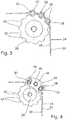
- Figure 3 illustrates three adjacent force drivers 22 which are arranged on the toothed belt 20.
- the toothed disk 26 has tooth recesses 40 for receiving and driving the teeth of the toothed belt 20, as well as force driver recesses 42 for receiving and driving the force drivers 22. If the toothed pulley 26 drives the toothed belt and the force drivers 22 are located in the force driver recess 42, the drive force of the toothed pulley 26 is transmitted directly to it.
- FIG. 4 the function of a connecting plate 44 according to the invention becomes clear in a simplified representation.
- a connecting plate 44 is shown which connects the three force drivers 22 to one another in the pulling direction of the toothed belt 20.
- the middle force driver 22 is not rotatably mounted.
- the connecting plate 44 also has two curved elongated holes 48 into which each of the cylindrical protrusions of the outer force driver 22 extend.
- the rollers 80 arranged on these are not shown.
- the curved elongated holes 48 allow the connecting plate 44 to pivot during the change in direction through the toothed disk 26.
- the connecting plate 44 causes forces to be distributed to the three force drivers 22 and at the same time the tension of the toothed belt 20 remains unchanged.
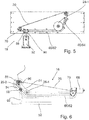
- FIG. 5 shows a preferred embodiment of a drive device 18 according to the invention in a simplified representation of the principle.
- An element driver 92 can be seen, which is mounted pivotably on a drive means 90 of the force driver element 56.
- the element driver 92 is used to connect to the element to be driven, for example a door 50 (not shown).
- the force driver element 56 is connected to the toothed belt 20.
- Unrecognizable rollers 80 arranged on the end of the force drivers 22 are guided in a guide track 60.
- the guideway 60 has a first straight route section 62 and a second straight route section 64.
- a preferably electric drive motor 68 (cf. Fig. 6 ) drives the toothed belt 20 via a pinion 70.
- a first toothed disk 26 - 1 is arranged in the region of the transition from the first route section 62 to the second route section 64.
- the door 50 is in the open position.
- Figure 5 also shows that only three force driver recesses 42 are provided for driving the force driver 22. Since the force drivers 22 always cover exactly the same path, the first toothed pulley 26-1 and can also be matched exactly to the position of the force drivers 22; the device only needs to be preset once. It can also be seen that only the pinion 70 is driven, but not the first toothed disk 26-1. This effectively prevents the force driver 22 from slipping on the first toothed slide 26-1.
- Figure 6 illustrates a variant with over-center position.
- a second toothed disk 26 - 2 is arranged in the area of the curved end-side section 66.
- the force driver element 56 is moved from the first section 62 to the arcuate end section 66, but does not pass the pinion 70. In this respect, it also has no force driver cutouts 42, but only tooth cutouts 40.
- an over-center position is reached. This is illustrated by the drawn line L.
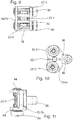
- FIG. 7 to 11 illustrate the structure of the force driver element 56.
- a central force driver 22-1 is arranged, which is not pivotable or rotatable.
- a second force driver 22-2 and a third force driver 22-3 is arranged, which can be pivoted due to the elongated holes 48 so that the force driver element 56 can move around the toothed pulleys 26.
- the frame element 72 basically forms two opposing connecting plates 44 and a connecting wall 76 which connects the two connecting plates to one another.
- the outer force drivers 22 extend through the elongated holes 48 and have rollers 80.
- a drive means 90 is provided which is connected to the frame element 72 and is used to connect to the element driver 92 to be driven.
- the drive means 90 is preferably connected to the connecting wall 76 in a rotationally fixed manner. It preferably forms a pivot point for connecting an element driver 92, which in turn is connected to the element to be driven, that is to say for example the door 50.
- the drive means 90 can have a driver opening 94 which is aligned parallel to the force drivers 22 and in which a driver axis 96 of the element driver 92 is rotatably mounted.
- the invention is not limited to the exemplary embodiments described, but also includes further design variants which are covered by the patent claims.
- more force drivers 22 can also be provided.
- An arrangement of connecting plates 44 on both sides of the force drivers 22 is also conceivable.
Landscapes
- Engineering & Computer Science (AREA)
- Mechanical Engineering (AREA)
- Power-Operated Mechanisms For Wings (AREA)
- Transmission Devices (AREA)
- Devices For Conveying Motion By Means Of Endless Flexible Members (AREA)
Claims (14)
- Dispositif d'entraînement (18) pour entraîner un élément comprenant- une commande à courroie crantée comprenant une courroie crantée (20),- un élément de cadre (72)- un disque denté (26) ayant des évidements pour dents (40) destinés à entraîner des dents de la courroie crantée (20),- une glissière (60) non linéaire qui s'étend au moins par sections parallèlement à l'extension de la courroie crantée (20) et dans laquelle sont guidés les rouleaux (80) disposés sur un entraîneur à force extérieur (22-2, 22-3),- un moyen d'entraînement (90) qui est relié à l'élément de cadre (72) et sert à la liaison à l'élément à entraîner,
caractérisé par le fait que- l'élément de cadre (72) forme deux plaques de liaison (44) opposées et une paroi de liaison (76) qui relie les deux plaques de liaison (44) l'une à l'autre,- le dispositif d'entraînement (18) comprend au moins trois entraîneurs à force (22) allongés qui sont fixés à la courroie crantée (20) et sont orientés parallèlement à une largeur B de la courroie crantée (20) et parallèles entre eux, et qui- sont agencés à l'intérieur de l'élément de cadre (72), dans lequel un entraîneur à force central (22-1) est fixé de manière solidaire en rotation aux deux plaques de liaison (44), et des sections d'extrémité des entraîneurs à force (22) extérieurs adjacents s'étendent chacune à travers des trous oblong (48) incurvés de la plaque de liaison (44) ce par quoi les entraîneurs à force extérieurs (22-2, 22-3) peuvent pivoter, et, à l'extrémité hors de l'une des plaques de liaison (44), les entraîneurs à force extérieurs (22-2, 22-3) présentent des saillies cylindriques qui sont conçues en tant que fusées d'essieu et portent chacune un rouleau (80),- ledit disque denté (26) présente des évidements pour entraîneur à force (42) destinés à entraîner les entraîneurs à force (22). - Dispositif d'entraînement (18) selon la revendication 1, caractérisé par le fait que ledit moyen d'entraînement (90) est relié de manière solidaire en rotation à la paroi de liaison (76).
- Dispositif d'entraînement (18) selon la revendication 2, caractérisé par le fait que le moyen d'entraînement (90) forme un point de pivotement pour connecter un entraîneur d'élément (92).
- Dispositif d'entraînement (18) selon la revendication 3, caractérisé par le fait que le moyen d'entraînement (90) présente une ouverture d'entraînement (94) qui est orientée parallèlement aux entraîneurs à force (22) et dans laquelle un axe d'entraîneur (96) de l'entraîneur d'élément (92) est logé de manière rotative.
- Dispositif d'entraînement (18) selon l'une quelconque des revendications 1 à 4, caractérisé par le fait que la glissière (60) présente une section de trajet (66) en arc de sorte que lesdits entraîneurs à force (22) peuvent être déplacés autour dudit disque denté (26) de manière à ce qu'il en résulte une position à dépassement de point mort.
- Dispositif d'entraînement (18) selon l'une quelconque des revendications 1 à 5, caractérisé par le fait que ledit disque denté (26) est conçu en tant que pignon entraîné.
- Dispositif d'entraînement (18) selon l'une quelconque des revendications 1 à 6, caractérisé par le fait qu'un pignon entraîné ayant uniquement des évidements pour dents (40) destinés à entraîner des dents de la courroie crantée (20) est prévu.
- Dispositif d'entraînement (18) selon l'une quelconque des revendications 1 à 7, caractérisé par le fait que la glissière (60) présente une première section de chemin (62) droite, une deuxième section de chemin (64) droite et une section de chemin d'extrémité (66) en arc, dans lequel les deux sections de chemin (62, 64) droites sont disposées de façon angulaire l'une par rapport à l'autre.
- Dispositif d'entraînement (18) selon la revendication 8, caractérisé par le fait qu'un pignon entraîné est disposé à une extrémité libre de la première section de chemin (62) droite, un premier disque denté (26-1) est disposé au niveau du passage de la première section de chemin (62) droite à la deuxième section de chemin (64) droite et un deuxième disque denté (26-2) est disposé au niveau de la section de chemin d'extrémité (66) en arc, et les entraîneurs à force (22) peuvent être déplacés autour du deuxième disque denté (26-2) de telle manière que l'on obtienne une position à dépassement de point mort par rapport à un mouvement de retour de l'élément à entraîner.
- Dispositif d'entraînement (18) selon l'une quelconque des revendications 1 à 9, caractérisé par le fait que l'élément entraîné est une porte (50).
- Dispositif d'entraînement (18) selon l'une quelconque des revendications 1 à 10, caractérisé par le fait que lesdits entraîneurs à force (22) sont reliés à la courroie crantée (20) via une liaison par serrage.
- Dispositif d'entraînement (18) selon la revendication 11, caractérisé par le fait que les entraîneurs à force (22) sont réalisés en deux parties et comprennent une partie inférieure (32) disposée, à l'état de fixation, sur un côté intérieur (28) de la courroie crantée (20) ainsi qu'une partie supérieure (30) disposée sur un côté extérieur (24) de la courroie crantée (20), lesquelles peuvent être reliées entre elles de manière à serrer la courroie crantée (20) entre elles.
- Dispositif d'entraînement (18) selon la revendication 12, caractérisé par le fait que la partie supérieure (30) et la partie inférieure (32) sont vissées l'une avec l'autre à l'état fixé.
- Dispositif d'entraînement (18) selon l'une quelconque des revendications 11 à 13, caractérisé par le fait que les entraîneurs à force (22) présentent une longueur L qui, à l'état fixé, s'étend parallèlement à une largeur B de la courroie crantée (20) et qui dépasse la largeur B de la courroie crantée (20), dans lequel la partie inférieure (32) et la partie supérieure (30) sont reliées entre elles par des moyens de liaison (34) qui s'étendent latéralement à côté de la courroie crantée (20).
Priority Applications (1)
| Application Number | Priority Date | Filing Date | Title |
|---|---|---|---|
| PL16801397T PL3538730T3 (pl) | 2016-11-11 | 2016-11-11 | Urządzenie napędowe dla elementu napędzanego |
Applications Claiming Priority (1)
| Application Number | Priority Date | Filing Date | Title |
|---|---|---|---|
| PCT/EP2016/077457 WO2018086705A1 (fr) | 2016-11-11 | 2016-11-11 | Dispositif d'entraînement pour un élément à entraîner |
Publications (2)
| Publication Number | Publication Date |
|---|---|
| EP3538730A1 EP3538730A1 (fr) | 2019-09-18 |
| EP3538730B1 true EP3538730B1 (fr) | 2020-12-30 |
Family
ID=57396402
Family Applications (1)
| Application Number | Title | Priority Date | Filing Date |
|---|---|---|---|
| EP16801397.7A Active EP3538730B1 (fr) | 2016-11-11 | 2016-11-11 | Dispositif d'entraînement pour un élément à entraîner |
Country Status (6)
| Country | Link |
|---|---|
| US (1) | US11447994B2 (fr) |
| EP (1) | EP3538730B1 (fr) |
| CN (1) | CN109963998B (fr) |
| ES (1) | ES2856693T3 (fr) |
| PL (1) | PL3538730T3 (fr) |
| WO (1) | WO2018086705A1 (fr) |
Families Citing this family (2)
| Publication number | Priority date | Publication date | Assignee | Title |
|---|---|---|---|---|
| PL3538730T3 (pl) | 2016-11-11 | 2021-06-14 | Gebr. Bode Gmbh & Co. Kg | Urządzenie napędowe dla elementu napędzanego |
| CN110395094A (zh) * | 2019-06-28 | 2019-11-01 | 江西科技学院 | 一种车门系统及汽车 |
Citations (1)
| Publication number | Priority date | Publication date | Assignee | Title |
|---|---|---|---|---|
| EP3239448A1 (fr) * | 2016-04-28 | 2017-11-01 | Daniel Bencina | Dispositif d'actionnement pour une porte coulissante de véhicule automobile |
Family Cites Families (30)
| Publication number | Priority date | Publication date | Assignee | Title |
|---|---|---|---|---|
| JPH0749746B2 (ja) * | 1990-06-29 | 1995-05-31 | 株式会社大井製作所 | スライドドアの自動開閉装置 |
| DE19814670B8 (de) * | 1997-04-02 | 2007-02-08 | Asmo Co., Ltd., Kosai | Versorgungseinrichtung für eine Schiebetür |
| DE29808567U1 (de) * | 1998-05-12 | 1999-09-23 | Hörmann KG Antriebstechnik, 33790 Halle | Führungs- oder An- bzw. Abtriebsrad für ein Zahngurtgetriebe sowie damit versehener Zahngurtantrieb |
| JP2000297579A (ja) * | 1999-04-16 | 2000-10-24 | Yazaki Corp | 自動車用スライドドアの給電装置 |
| US7032349B2 (en) * | 2000-04-27 | 2006-04-25 | Atoma International Corp. | Coreless motor door closure system for motor vehicles |
| FR2820453B1 (fr) * | 2001-02-05 | 2003-09-19 | Oxford Automotive Mecanismes E | Dispositif d'entrainement de porte coulissante d'un vehicule automobile et vehicule equipe d'un tel dispositif |
| US6464287B2 (en) * | 2001-03-12 | 2002-10-15 | Delphi Technologies, Inc. | Drive mechanism for power operated slideable side door |
| US6481783B1 (en) * | 2001-04-25 | 2002-11-19 | Delphi Technologies, Inc. | Drive mechanism for power operated slideable side door |
| US6807775B2 (en) * | 2003-03-12 | 2004-10-26 | Arvinmeritor Technology, Llc | Power sliding vehicle door |
| US7243461B2 (en) * | 2003-03-19 | 2007-07-17 | Rogers Jr Lloyd W | Hinge mechanism for a sliding door |
| US7325361B2 (en) * | 2003-03-19 | 2008-02-05 | Delphi Technologies, Inc. | Apparatus and method for providing a modular sliding door mechanism |
| US7144068B2 (en) * | 2003-11-20 | 2006-12-05 | Intier Automotive Closures Inc. | Drive mechanism for selectively opening and closing a closure panel manually or automatically |
| DE602005023817D1 (de) * | 2004-08-26 | 2010-11-11 | Aisin Seiki | Öffnungs/Schliessvorrichtung für eine Fahrzeugtür |
| DE102005005802B3 (de) * | 2005-02-09 | 2006-06-14 | Hübner GmbH | Ausstellschiebetürsystem für ein Fahrzeug |
| DE202005005571U1 (de) * | 2005-04-07 | 2006-05-18 | Dbt Gmbh | Kettenführungselement für Antriebsketten von untertägigen Gewinnungsgeräten |
| JP2006348668A (ja) * | 2005-06-17 | 2006-12-28 | Mitsuba Corp | スライドドア開閉装置 |
| JP4789588B2 (ja) * | 2005-11-11 | 2011-10-12 | アイシン精機株式会社 | 車両用スライドドア開閉装置 |
| WO2008113178A1 (fr) * | 2007-03-21 | 2008-09-25 | Magna Closures Inc. | Porte coulissante à énergie de transmission par courroie avec tendeur de courroie |
| JP5083298B2 (ja) * | 2009-11-20 | 2012-11-28 | アイシン精機株式会社 | ステップユニット |
| CN203580583U (zh) * | 2010-12-24 | 2014-05-07 | 爱信精机株式会社 | 滑门开闭装置 |
| CN102296904B (zh) * | 2011-08-26 | 2014-04-02 | 南京工程学院 | 一种塞拉门齿带单轴导杆槽型凸轮组合空间机构 |
| GB2532176B (en) * | 2014-05-20 | 2020-12-30 | Sg Technical Systems Ltd | Access doors |
| JP6446722B2 (ja) * | 2014-08-06 | 2019-01-09 | 三井金属アクト株式会社 | ドア開閉装置 |
| JP6446724B2 (ja) * | 2014-08-06 | 2019-01-09 | 三井金属アクト株式会社 | ドア開閉装置 |
| JP6446723B2 (ja) * | 2014-08-06 | 2019-01-09 | 三井金属アクト株式会社 | ドア開閉装置 |
| KR101610157B1 (ko) * | 2014-11-06 | 2016-04-08 | 현대자동차 주식회사 | 차량용 도어 슬라이더장치 |
| PL3061685T3 (pl) * | 2015-02-24 | 2017-06-30 | Airbus Helicopters Deutschland GmbH | Przesuwny element zamykający, zwłaszcza przesuwne drzwi albo przesuwne okno, do zespołu przesuwnego elementu zamykającego środka transportu, w szczególności statku powietrznego |
| DE202016001776U1 (de) * | 2016-03-18 | 2017-06-21 | Gebr. Bode Gmbh & Co. Kg | Zahnriemenantrieb mit Kraftmitnehmern |
| CN205654793U (zh) * | 2016-05-25 | 2016-10-19 | 象山影视象农产品加工厂 | 纺织机用皮带绷紧装置 |
| PL3538730T3 (pl) | 2016-11-11 | 2021-06-14 | Gebr. Bode Gmbh & Co. Kg | Urządzenie napędowe dla elementu napędzanego |
-
2016
- 2016-11-11 PL PL16801397T patent/PL3538730T3/pl unknown
- 2016-11-11 US US16/349,288 patent/US11447994B2/en active Active
- 2016-11-11 CN CN201680090717.7A patent/CN109963998B/zh active Active
- 2016-11-11 EP EP16801397.7A patent/EP3538730B1/fr active Active
- 2016-11-11 WO PCT/EP2016/077457 patent/WO2018086705A1/fr unknown
- 2016-11-11 ES ES16801397T patent/ES2856693T3/es active Active
Patent Citations (1)
| Publication number | Priority date | Publication date | Assignee | Title |
|---|---|---|---|---|
| EP3239448A1 (fr) * | 2016-04-28 | 2017-11-01 | Daniel Bencina | Dispositif d'actionnement pour une porte coulissante de véhicule automobile |
Also Published As
| Publication number | Publication date |
|---|---|
| ES2856693T3 (es) | 2021-09-28 |
| WO2018086705A1 (fr) | 2018-05-17 |
| EP3538730A1 (fr) | 2019-09-18 |
| US20200165853A1 (en) | 2020-05-28 |
| CN109963998B (zh) | 2021-01-26 |
| PL3538730T3 (pl) | 2021-06-14 |
| CN109963998A (zh) | 2019-07-02 |
| US11447994B2 (en) | 2022-09-20 |
Similar Documents
| Publication | Publication Date | Title |
|---|---|---|
| EP2947346B1 (fr) | Chaîne autoportante 3D | |
| EP1568563B1 (fr) | Dispositif de verrouillage d'une porte coulissante et pivotante pour véhicules pour le transport de personnes, notamment véhicules de transport urbain de personnes | |
| EP2050912A2 (fr) | Elément de rail et entraînement de portail | |
| EP3538730B1 (fr) | Dispositif d'entraînement pour un élément à entraîner | |
| DE2836398A1 (de) | Fensterheber | |
| WO2011120781A1 (fr) | Porte coulissante dotée de panneaux empilables | |
| EP1733113A1 (fr) | Cassette pour la transmission de force dans un leve-vitre | |
| EP3235994B1 (fr) | Dispositif d'entraînement pour un élément à entraîner | |
| EP3430285B1 (fr) | Transmission par courroie crantée comportant des moyens d'entraînement mécanique | |
| WO2022084146A1 (fr) | Entraînement de portière pour système de portière coulissante de véhicule | |
| EP1617102A2 (fr) | Chaîne pour un dispositif de pivotement pour l'ouverture et la fermeture de volets, portes, fenêtres ou analogues | |
| DE3737385C2 (de) | Vorrichtung zum Öffnen und Schließen eines Tores | |
| WO2020136184A1 (fr) | Dispositif pour le verrouillage de portes à charnières ainsi que porte à charnières comprenant un tel dispositif | |
| DE102007030139B4 (de) | Verstellantrieb zur Bewegung eines Funktionselementes in oder an einer Kraftfahrzeugkarosserie | |
| DE19816564C1 (de) | Torantrieb | |
| DE102017203008A1 (de) | Seilführungsanordnung für eine fremdkraftbetätigte Fahrzeugschiebetür | |
| AT520902B1 (de) | Kreuzspindelantrieb mit Verriegelungsvorrichtung für Schiebetüren und Schwenk-Schiebetüren für Schienenfahrzeuge zum Personentransport | |
| DE102009058678B4 (de) | Verstellvorrichtung zum Verstellen, insbesondere zum translatorischen Verschieben, wenigstens eines Möbelteils | |
| EP0728269B1 (fr) | Element de transmission de force | |
| DE102008058242A1 (de) | Schiebetüranordnung | |
| DE102015000658B4 (de) | Antriebsvorrichtung für ein automatisiertes Garagentor | |
| DE102015117625A1 (de) | Einrichtung zur Realisierung einer Verschwenkkraftkomponente | |
| EP4359281A1 (fr) | Dispositif d'étanchéité/verrouillage actif selon le principe de constriction | |
| DE102017000233A1 (de) | Antriebssystem für ein Torblatt | |
| DE3423786A1 (de) | Antriebsvorrichtung zum oeffnen und schliessen einer tuer, vorzugsweise einer kabinentuer eines aufzuges |
Legal Events
| Date | Code | Title | Description |
|---|---|---|---|
| STAA | Information on the status of an ep patent application or granted ep patent |
Free format text: STATUS: UNKNOWN |
|
| STAA | Information on the status of an ep patent application or granted ep patent |
Free format text: STATUS: THE INTERNATIONAL PUBLICATION HAS BEEN MADE |
|
| PUAI | Public reference made under article 153(3) epc to a published international application that has entered the european phase |
Free format text: ORIGINAL CODE: 0009012 |
|
| STAA | Information on the status of an ep patent application or granted ep patent |
Free format text: STATUS: REQUEST FOR EXAMINATION WAS MADE |
|
| 17P | Request for examination filed |
Effective date: 20190507 |
|
| AK | Designated contracting states |
Kind code of ref document: A1 Designated state(s): AL AT BE BG CH CY CZ DE DK EE ES FI FR GB GR HR HU IE IS IT LI LT LU LV MC MK MT NL NO PL PT RO RS SE SI SK SM TR |
|
| AX | Request for extension of the european patent |
Extension state: BA ME |
|
| DAV | Request for validation of the european patent (deleted) | ||
| DAX | Request for extension of the european patent (deleted) | ||
| GRAP | Despatch of communication of intention to grant a patent |
Free format text: ORIGINAL CODE: EPIDOSNIGR1 |
|
| STAA | Information on the status of an ep patent application or granted ep patent |
Free format text: STATUS: GRANT OF PATENT IS INTENDED |
|
| INTG | Intention to grant announced |
Effective date: 20200706 |
|
| GRAS | Grant fee paid |
Free format text: ORIGINAL CODE: EPIDOSNIGR3 |
|
| GRAA | (expected) grant |
Free format text: ORIGINAL CODE: 0009210 |
|
| STAA | Information on the status of an ep patent application or granted ep patent |
Free format text: STATUS: THE PATENT HAS BEEN GRANTED |
|
| AK | Designated contracting states |
Kind code of ref document: B1 Designated state(s): AL AT BE BG CH CY CZ DE DK EE ES FI FR GB GR HR HU IE IS IT LI LT LU LV MC MK MT NL NO PL PT RO RS SE SI SK SM TR |
|
| REG | Reference to a national code |
Ref country code: GB Ref legal event code: FG4D Free format text: NOT ENGLISH |
|
| REG | Reference to a national code |
Ref country code: DE Ref legal event code: R096 Ref document number: 502016012093 Country of ref document: DE |
|
| REG | Reference to a national code |
Ref country code: AT Ref legal event code: REF Ref document number: 1350083 Country of ref document: AT Kind code of ref document: T Effective date: 20210115 |
|
| REG | Reference to a national code |
Ref country code: IE Ref legal event code: FG4D Free format text: LANGUAGE OF EP DOCUMENT: GERMAN |
|
| REG | Reference to a national code |
Ref country code: NL Ref legal event code: FP |
|
| REG | Reference to a national code |
Ref country code: SE Ref legal event code: TRGR |
|
| PG25 | Lapsed in a contracting state [announced via postgrant information from national office to epo] |
Ref country code: GR Free format text: LAPSE BECAUSE OF FAILURE TO SUBMIT A TRANSLATION OF THE DESCRIPTION OR TO PAY THE FEE WITHIN THE PRESCRIBED TIME-LIMIT Effective date: 20210331 Ref country code: FI Free format text: LAPSE BECAUSE OF FAILURE TO SUBMIT A TRANSLATION OF THE DESCRIPTION OR TO PAY THE FEE WITHIN THE PRESCRIBED TIME-LIMIT Effective date: 20201230 Ref country code: NO Free format text: LAPSE BECAUSE OF FAILURE TO SUBMIT A TRANSLATION OF THE DESCRIPTION OR TO PAY THE FEE WITHIN THE PRESCRIBED TIME-LIMIT Effective date: 20210330 Ref country code: RS Free format text: LAPSE BECAUSE OF FAILURE TO SUBMIT A TRANSLATION OF THE DESCRIPTION OR TO PAY THE FEE WITHIN THE PRESCRIBED TIME-LIMIT Effective date: 20201230 |
|
| PG25 | Lapsed in a contracting state [announced via postgrant information from national office to epo] |
Ref country code: BG Free format text: LAPSE BECAUSE OF FAILURE TO SUBMIT A TRANSLATION OF THE DESCRIPTION OR TO PAY THE FEE WITHIN THE PRESCRIBED TIME-LIMIT Effective date: 20210330 Ref country code: LV Free format text: LAPSE BECAUSE OF FAILURE TO SUBMIT A TRANSLATION OF THE DESCRIPTION OR TO PAY THE FEE WITHIN THE PRESCRIBED TIME-LIMIT Effective date: 20201230 |
|
| PG25 | Lapsed in a contracting state [announced via postgrant information from national office to epo] |
Ref country code: HR Free format text: LAPSE BECAUSE OF FAILURE TO SUBMIT A TRANSLATION OF THE DESCRIPTION OR TO PAY THE FEE WITHIN THE PRESCRIBED TIME-LIMIT Effective date: 20201230 |
|
| REG | Reference to a national code |
Ref country code: LT Ref legal event code: MG9D |
|
| PG25 | Lapsed in a contracting state [announced via postgrant information from national office to epo] |
Ref country code: PT Free format text: LAPSE BECAUSE OF FAILURE TO SUBMIT A TRANSLATION OF THE DESCRIPTION OR TO PAY THE FEE WITHIN THE PRESCRIBED TIME-LIMIT Effective date: 20210430 Ref country code: RO Free format text: LAPSE BECAUSE OF FAILURE TO SUBMIT A TRANSLATION OF THE DESCRIPTION OR TO PAY THE FEE WITHIN THE PRESCRIBED TIME-LIMIT Effective date: 20201230 Ref country code: SK Free format text: LAPSE BECAUSE OF FAILURE TO SUBMIT A TRANSLATION OF THE DESCRIPTION OR TO PAY THE FEE WITHIN THE PRESCRIBED TIME-LIMIT Effective date: 20201230 Ref country code: EE Free format text: LAPSE BECAUSE OF FAILURE TO SUBMIT A TRANSLATION OF THE DESCRIPTION OR TO PAY THE FEE WITHIN THE PRESCRIBED TIME-LIMIT Effective date: 20201230 Ref country code: LT Free format text: LAPSE BECAUSE OF FAILURE TO SUBMIT A TRANSLATION OF THE DESCRIPTION OR TO PAY THE FEE WITHIN THE PRESCRIBED TIME-LIMIT Effective date: 20201230 |
|
| REG | Reference to a national code |
Ref country code: ES Ref legal event code: FG2A Ref document number: 2856693 Country of ref document: ES Kind code of ref document: T3 Effective date: 20210928 |
|
| PG25 | Lapsed in a contracting state [announced via postgrant information from national office to epo] |
Ref country code: IS Free format text: LAPSE BECAUSE OF FAILURE TO SUBMIT A TRANSLATION OF THE DESCRIPTION OR TO PAY THE FEE WITHIN THE PRESCRIBED TIME-LIMIT Effective date: 20210430 |
|
| REG | Reference to a national code |
Ref country code: DE Ref legal event code: R097 Ref document number: 502016012093 Country of ref document: DE |
|
| PG25 | Lapsed in a contracting state [announced via postgrant information from national office to epo] |
Ref country code: AL Free format text: LAPSE BECAUSE OF FAILURE TO SUBMIT A TRANSLATION OF THE DESCRIPTION OR TO PAY THE FEE WITHIN THE PRESCRIBED TIME-LIMIT Effective date: 20201230 |
|
| PLBE | No opposition filed within time limit |
Free format text: ORIGINAL CODE: 0009261 |
|
| STAA | Information on the status of an ep patent application or granted ep patent |
Free format text: STATUS: NO OPPOSITION FILED WITHIN TIME LIMIT |
|
| PG25 | Lapsed in a contracting state [announced via postgrant information from national office to epo] |
Ref country code: DK Free format text: LAPSE BECAUSE OF FAILURE TO SUBMIT A TRANSLATION OF THE DESCRIPTION OR TO PAY THE FEE WITHIN THE PRESCRIBED TIME-LIMIT Effective date: 20201230 |
|
| 26N | No opposition filed |
Effective date: 20211001 |
|
| REG | Reference to a national code |
Ref country code: DE Ref legal event code: R081 Ref document number: 502016012093 Country of ref document: DE Owner name: BODE - DIE TUER GMBH, DE Free format text: FORMER OWNER: GEBR. BODE GMBH & CO. KG, 34123 KASSEL, DE |
|
| PG25 | Lapsed in a contracting state [announced via postgrant information from national office to epo] |
Ref country code: SI Free format text: LAPSE BECAUSE OF FAILURE TO SUBMIT A TRANSLATION OF THE DESCRIPTION OR TO PAY THE FEE WITHIN THE PRESCRIBED TIME-LIMIT Effective date: 20201230 |
|
| PG25 | Lapsed in a contracting state [announced via postgrant information from national office to epo] |
Ref country code: IS Free format text: LAPSE BECAUSE OF FAILURE TO SUBMIT A TRANSLATION OF THE DESCRIPTION OR TO PAY THE FEE WITHIN THE PRESCRIBED TIME-LIMIT Effective date: 20210430 |
|
| PG25 | Lapsed in a contracting state [announced via postgrant information from national office to epo] |
Ref country code: MC Free format text: LAPSE BECAUSE OF FAILURE TO SUBMIT A TRANSLATION OF THE DESCRIPTION OR TO PAY THE FEE WITHIN THE PRESCRIBED TIME-LIMIT Effective date: 20201230 |
|
| PG25 | Lapsed in a contracting state [announced via postgrant information from national office to epo] |
Ref country code: LU Free format text: LAPSE BECAUSE OF NON-PAYMENT OF DUE FEES Effective date: 20211111 Ref country code: BE Free format text: LAPSE BECAUSE OF NON-PAYMENT OF DUE FEES Effective date: 20211130 |
|
| REG | Reference to a national code |
Ref country code: BE Ref legal event code: MM Effective date: 20211130 |
|
| PG25 | Lapsed in a contracting state [announced via postgrant information from national office to epo] |
Ref country code: IE Free format text: LAPSE BECAUSE OF NON-PAYMENT OF DUE FEES Effective date: 20211111 |
|
| PG25 | Lapsed in a contracting state [announced via postgrant information from national office to epo] |
Ref country code: CY Free format text: LAPSE BECAUSE OF FAILURE TO SUBMIT A TRANSLATION OF THE DESCRIPTION OR TO PAY THE FEE WITHIN THE PRESCRIBED TIME-LIMIT Effective date: 20201230 |
|
| PG25 | Lapsed in a contracting state [announced via postgrant information from national office to epo] |
Ref country code: SM Free format text: LAPSE BECAUSE OF FAILURE TO SUBMIT A TRANSLATION OF THE DESCRIPTION OR TO PAY THE FEE WITHIN THE PRESCRIBED TIME-LIMIT Effective date: 20201230 Ref country code: HU Free format text: LAPSE BECAUSE OF FAILURE TO SUBMIT A TRANSLATION OF THE DESCRIPTION OR TO PAY THE FEE WITHIN THE PRESCRIBED TIME-LIMIT; INVALID AB INITIO Effective date: 20161111 |
|
| PGFP | Annual fee paid to national office [announced via postgrant information from national office to epo] |
Ref country code: NL Payment date: 20231122 Year of fee payment: 8 |
|
| PGFP | Annual fee paid to national office [announced via postgrant information from national office to epo] |
Ref country code: GB Payment date: 20231123 Year of fee payment: 8 |
|
| PGFP | Annual fee paid to national office [announced via postgrant information from national office to epo] |
Ref country code: ES Payment date: 20231215 Year of fee payment: 8 |
|
| PGFP | Annual fee paid to national office [announced via postgrant information from national office to epo] |
Ref country code: TR Payment date: 20231031 Year of fee payment: 8 Ref country code: SE Payment date: 20231123 Year of fee payment: 8 Ref country code: IT Payment date: 20231130 Year of fee payment: 8 Ref country code: FR Payment date: 20231122 Year of fee payment: 8 Ref country code: DE Payment date: 20231120 Year of fee payment: 8 Ref country code: CZ Payment date: 20231027 Year of fee payment: 8 Ref country code: CH Payment date: 20231202 Year of fee payment: 8 Ref country code: AT Payment date: 20231117 Year of fee payment: 8 |
|
| PGFP | Annual fee paid to national office [announced via postgrant information from national office to epo] |
Ref country code: PL Payment date: 20231031 Year of fee payment: 8 |
|
| PG25 | Lapsed in a contracting state [announced via postgrant information from national office to epo] |
Ref country code: MK Free format text: LAPSE BECAUSE OF FAILURE TO SUBMIT A TRANSLATION OF THE DESCRIPTION OR TO PAY THE FEE WITHIN THE PRESCRIBED TIME-LIMIT Effective date: 20201230 |
|
| PG25 | Lapsed in a contracting state [announced via postgrant information from national office to epo] |
Ref country code: MT Free format text: LAPSE BECAUSE OF FAILURE TO SUBMIT A TRANSLATION OF THE DESCRIPTION OR TO PAY THE FEE WITHIN THE PRESCRIBED TIME-LIMIT Effective date: 20201230 |