EP3530867A1 - Vorrichtung zum beschatten einer gebäudeöffnung - Google Patents
Vorrichtung zum beschatten einer gebäudeöffnung Download PDFInfo
- Publication number
- EP3530867A1 EP3530867A1 EP19020029.5A EP19020029A EP3530867A1 EP 3530867 A1 EP3530867 A1 EP 3530867A1 EP 19020029 A EP19020029 A EP 19020029A EP 3530867 A1 EP3530867 A1 EP 3530867A1
- Authority
- EP
- European Patent Office
- Prior art keywords
- electric motor
- switch
- curtain
- rocker
- arm
- Prior art date
- Legal status (The legal status is an assumption and is not a legal conclusion. Google has not performed a legal analysis and makes no representation as to the accuracy of the status listed.)
- Granted
Links
Images


Classifications
-
- E—FIXED CONSTRUCTIONS
- E06—DOORS, WINDOWS, SHUTTERS, OR ROLLER BLINDS IN GENERAL; LADDERS
- E06B—FIXED OR MOVABLE CLOSURES FOR OPENINGS IN BUILDINGS, VEHICLES, FENCES OR LIKE ENCLOSURES IN GENERAL, e.g. DOORS, WINDOWS, BLINDS, GATES
- E06B9/00—Screening or protective devices for wall or similar openings, with or without operating or securing mechanisms; Closures of similar construction
- E06B9/24—Screens or other constructions affording protection against light, especially against sunshine; Similar screens for privacy or appearance; Slat blinds
- E06B9/26—Lamellar or like blinds, e.g. venetian blinds
- E06B9/28—Lamellar or like blinds, e.g. venetian blinds with horizontal lamellae, e.g. non-liftable
- E06B9/30—Lamellar or like blinds, e.g. venetian blinds with horizontal lamellae, e.g. non-liftable liftable
- E06B9/32—Operating, guiding, or securing devices therefor
- E06B9/322—Details of operating devices, e.g. pulleys, brakes, spring drums, drives
-
- E—FIXED CONSTRUCTIONS
- E06—DOORS, WINDOWS, SHUTTERS, OR ROLLER BLINDS IN GENERAL; LADDERS
- E06B—FIXED OR MOVABLE CLOSURES FOR OPENINGS IN BUILDINGS, VEHICLES, FENCES OR LIKE ENCLOSURES IN GENERAL, e.g. DOORS, WINDOWS, BLINDS, GATES
- E06B9/00—Screening or protective devices for wall or similar openings, with or without operating or securing mechanisms; Closures of similar construction
- E06B9/24—Screens or other constructions affording protection against light, especially against sunshine; Similar screens for privacy or appearance; Slat blinds
- E06B9/26—Lamellar or like blinds, e.g. venetian blinds
- E06B9/28—Lamellar or like blinds, e.g. venetian blinds with horizontal lamellae, e.g. non-liftable
- E06B9/30—Lamellar or like blinds, e.g. venetian blinds with horizontal lamellae, e.g. non-liftable liftable
- E06B9/32—Operating, guiding, or securing devices therefor
- E06B9/323—Structure or support of upper box
-
- E—FIXED CONSTRUCTIONS
- E06—DOORS, WINDOWS, SHUTTERS, OR ROLLER BLINDS IN GENERAL; LADDERS
- E06B—FIXED OR MOVABLE CLOSURES FOR OPENINGS IN BUILDINGS, VEHICLES, FENCES OR LIKE ENCLOSURES IN GENERAL, e.g. DOORS, WINDOWS, BLINDS, GATES
- E06B9/00—Screening or protective devices for wall or similar openings, with or without operating or securing mechanisms; Closures of similar construction
- E06B9/56—Operating, guiding or securing devices or arrangements for roll-type closures; Spring drums; Tape drums; Counterweighting arrangements therefor
- E06B9/68—Operating devices or mechanisms, e.g. with electric drive
- E06B2009/6809—Control
- E06B2009/689—Control using end switches
Definitions
- the invention relates to a device for shading a building opening, etc., in particular a Venetian blind, with a consisting of parallel superposed lamellae and a lower end rail curtain, the lamellae by a number of attacking on the end rail lifting belts to a stack of lamellas diveziehbar and downwards drainable and / or by a number of engaging on longitudinal sides of the lamellae turning belts are pivotable about a longitudinal axis parallel to the axis, and with a drive shaft driven by an electric motor containing drive unit for actuating the Hubb selected and / or the turning tapes, wherein the drive unit transverse to Behbehbene next to the lamella stack is arranged and the electric motor is associated with an off switch which is actuated by means of a transmission member to which the curtain starts on reaching its raised to a fin stack end position.
- a device for shading a building opening, etc. in particular a Venetian blind, with a consisting of parallel superposed lamellae and
- a device of this kind is from the DE 20 2010 013 522 U1 known.
- the electric motor is arranged with downwardly directed off switch.
- a height-adjustable Z-shaped bracket must be provided, on the one hand engages under the off switch and on the other hand engages over the disk set.
- the necessary here linear guide for the height-adjustable bracket is according to experience prone to tilting, contamination and stiffness, which can lead to malfunction.
- This object is achieved in that is arranged in a device of the type mentioned above, the electric motor with upwardly facing off-switch and that the transmission member is arranged above it, two-armed rocker, with one arm the curtain and the other arm the Off switch of the electric motor overlaps.
- the two-armed rocker advantageously requires no linear guide, but only a simple pivot bearing and therefore gives a very simple, low-interference design with high reliability.
- the two-armed rocker can be placed in an advantageous manner above the drive device and the lamella stack, so that no space is required in the area between the lamella stack and the adjacent drive device, a space-saving design favors. With the measures according to the invention, therefore, the above-mentioned object is achieved in a very simple and cost-effective manner.
- a housing may be provided for receiving the curtain and the adjacent drive means, the upper support means and a lower passage slot for the curtain and in which a drive device receiving, downwardly open rail profile forming header is arranged, the upper wall preferably from than Mushroom button trained off-switch is penetrated.
- the head unit containing the drive unit can be used as well as the curtain as a completely pre-assembled unit in the housing, so that in total results in a completely pre-assembled arrangement.
- the preassembled unit can therefore also advantageously contain the rocker acting as a transmission element.
- the rocker and the bearing block can be provided with rotating with degree of freedom nesting one another bearing elements, which allows easy assembly.
- a further advantageous measure may be that on the underside of the off-switch associated arm of the rocker a replaceable balance plate is releasably fixed.
- the compensating plate by means of a two spring legs having latching connection on the rocker be releasably fixed. This allows a simple, quick exchange.
- the higher-level measures can be provided in an electric motor, which is provided with the off switch adjacent switching buttons for adjusting the end positions of the curtain, that the Switching heads accessible via an associated recess of the upper wall of the head strip from above and can be actuated by means of a head strip from above overlapping, U-shaped adjustment bracket.
- the ends of the lateral limbs of the Einstellbügels are advantageously accessible from below, so that the adjustment of the end positions of the curtain can be performed from below.
- the lateral legs of the adjustment bracket can be provided for this purpose with lower handle tabs.
- a further expedient measure may be that the upper web of the adjustment bracket has projections associated with the push buttons, which increases the reliability.
- Another particularly advantageous measure may be that the lateral limbs of the adjustment bracket are equipped with at least one distinguishing feature.
- the adjustment bracket for this purpose consist of two symmetrical, differently colored, in the region of the upper web latching interconnected parts.
- Field of the invention are blinds or blinds.
- the drawing described below is based on a Venetian blind.
- the basic structure and operation of such arrangements are known per se and are therefore only mentioned below, as far as they may be of importance for understanding the invention.
- Venetian blind comprises a formed by parallel superposed lamellae 1 and a lower end rail 2, raisable and lowerable curtain 3, which forms a laminated core in the illustrated, pulled-up state and a lower passage slot in a in the region of the upper edge of a shaded building opening attachable, box-shaped housing 4 is retracted, from the lateral ends of the curtain 3 associated guide rails 5 can go down, into which the slats 1 and the end rail 2 can engage with lateral guide nipples not shown.
- the housing 4 may consist of several, at their ends facing each other hinged parts.
- Hubb For raising and lowering the blind 3 and for turning the slats 1 about an axis parallel to its longitudinal axis are several, distributed over the length of the slats 1, in Fig. 1 only indicated by broken lines Hubb only 6 and turning tapes 7 are provided.
- the Hubb selected 6 are performed by associated recesses of the slats 1 and engage the end rail 2 at.
- the curtain 3 is suspended from upper support members 8, which can rest with their ends on associated holders of the upper housing wall.
- the turning tapes 7 engage on at least one longitudinal side, here on both longitudinal sides of the slats 1 or act according to Art a ladder herewith together.
- the electric motor 10 is provided with a trained as a mushroom button off switch 14, by the curtain 3 when reaching his Fig. 1 underlying raised to a slat stack end position is actuated, so that practically results in an automatic limit.
- a transmission mechanism transmitting the switching movement 15 is provided, to which the curtain 3 starts when it reaches its upper end position and which consequently actuates the off switch 14.
- the electric motor 10 is placed in the head strip 12 in such a way that its off switch 14 projecting from one side faces upwards.
- the mushroom button forming the off switch 14 projects beyond the head strip 12, which is provided in the region of its upper web with a recess associated with the mushroom button forming the off switch 14, through which the mushroom button forming the off switch 14 can protrude.
- the transfer member 15 is as a patch on the header 12 rocker with two oppositely directed away from each other arms 16, 17 formed.
- the rocker is placed so that it overlaps with its arm 16 the curtain 3 and with its arm 17 off the switch 14 of the electric motor 10.
- the said rocker acts as a limit switch, which turns off the electric motor 10, as soon as the curtain 3 the has reached the desired upper end position.
- a bearing block 18 For receiving the transfer member 15 forming rocker 12 is a bearing block 18 is placed on the top of the header, on which the rocker is pivotally mounted.
- the storage of the two-armed rocker on the bearing block 18 is designed as a snap connection.
- the bearing block 18 and the two-armed rocker are provided with rotational freedom in each other snap-in bearing elements.
- the bearing block 18 is attached to a alsklippsten on the head strip 12, this comprehensive from above, U-shaped bracket 19.
- the lower ends of the lateral legs of the retaining clip 19 are formed as the lower ends of the side walls of the header 12 comprehensive spring claws.
- the headband 19 is like the upper web of the head strip 12 penetrated by the off-switch 14 forming mushroom button and this is according to Fig. 2 provided with an opaque above the above-mentioned the mushroom button associated recess of the upper web of the head strip 12 arranged feed-through recess 20.
- the suitable for uses of this type electric motors from different manufacturers have experience has different high mushroom button to form an off-switch 14. Therefore, on the bottom of the off-switch 14 associated arm 17 of the rocker an exchangeable balance plate 21 can be attached. Depending on the engine used different balancing plates 21 can be attached, whereby a universal usability is achieved.
- the compensating plate 21 is releasably secured to the associated arm 17 of the rocker.
- a latching connection is provided for this purpose, which on the one hand have two spring legs 22 provided with ratchet teeth, which rest on a web provided on the other 23 are latched.
- the desired end positions of the curtain 3 on the electric motor 10 are adjustable and therefore acts the the transmission member 15 forming rocker only as an emergency stop switch.
- Such an embodiment is the Fig. 2 based.
- the electric motor 10 with the mushroom button adjacent to his off-switch 14, with respect to the width of the head strip 12 laterally staggered buttons 24 for adjusting the top and uneren end position of the curtain 3 is provided. These are located next to the headband 19 and are accessible via a recess 25 of the upper web of the header 12 from above. This recess 25 may be a larger, the mushroom button and the switch buttons 24 jointly associated recess 25 acting on the off-switch 14.
- the adjustment bracket 26 is clipped in alignment with the buttons 24 on the header 12.
- preferably designed as elastic spring claws locking elements 27 are provided at the lower ends of its side legs on the lower ends of the side walls of the head strip 12 latched.
- operating tabs 28 can go down, which can be grasped directly by hand or by means of a tool.
- the upper web of the actuating bow 26 is provided with the push buttons 24 associated Tastvorsprüngen 29. Depending on which actuating tab 28 is pulled, one or the other switching button 24 is actuated.
- buttons 24 are colored differently in the rule. As a very obvious distinguishing feature, therefore, at least the actuating tabs 28 of the Einstellbügels 26 are also different, preferably colored in the same colors as the buttons 24.
- the adjustment bracket 26, as shown Fig. 3 can be seen, consist of two symmetrical, differently colored halves 26a, 26b, which overlap each other in the region of the upper web and can be clipped together.
- the two halves 26a, 26b are provided with interlocking connecting elements 30.
Landscapes
- Engineering & Computer Science (AREA)
- Structural Engineering (AREA)
- Architecture (AREA)
- Civil Engineering (AREA)
- Operating, Guiding And Securing Of Roll- Type Closing Members (AREA)
- Curtains And Furnishings For Windows Or Doors (AREA)
- Blinds (AREA)
Abstract
Description
- Die Erfindung betrifft eine Vorrichtung zum Beschatten einer Gebäudeöffnung etc., insbesondere einen Raffstore, mit einem aus parallel übereinander angeordneten Lamellen und einer unteren Endschiene bestehenden Behang, wobei die Lamellen durch eine Anzahl von an der Endschiene angreifenden Hubbändern zu einem Lamellenstapel hochziehbar und nach unten ablassbar oder/und durch eine Anzahl von an Längsseiten der Lamellen angreifenden Wendebändern um eine längsseitenparallele Achse schwenkbar sind, und mit einer eine mittels eines Elektromotors antreibbare Wickelwelle enthaltenden Antriebseinheit zur Betätigung der Hubbänder oder/und der Wendebänder, wobei die Antriebseinheit quer zur Behangebene neben dem Lamellenstapel angeordnet ist und dem Elektromotor ein Aus-Schalter zugeordnet ist, der mittels eines Übertragungsorgans betätigbar ist, an dem der Behang beim Erreichen seiner zu einem Lamellenstapel hochgezogenen Endlage anläuft.
- Eine Vorrichtung dieser Art ist aus der
DE 20 2010 013 522 U1 bekannt. Bei dieser bekannten Anordnung ist der Elektromotor mit nach unten gerichtetem Aus-Schalter angeordnet. Zur Bildung des Übertragungsorgans muss hierbei ein höhenbeweglicher Z-förmiger Bügel vorgesehen sein, der einerseits den Aus-Schalter untergreift und andererseits das Lamellenpaket übergreift. Die hier nötige Linearführung für den höhenbeweglichen Bügel ist erfahrungsgemäß anfällig für Verkanten, Verschmutzen und Schwergängigkeit, was zu Funktionsstörungen führen kann. Ein weiterer, besonderer Nachteil der bekannten Anordnung ergibt sich aus dem vergleichsweise hohen Platzbedarf im Bereich zwischen dem Lamellenstapel und der daneben angeordneten Antriebseinheit, was einer kompakten Bauweise entgegensteht bzw. bei beengten Verhältnissen dazu führen kann, dass sich die Lamellen an den Elementen der Linearführung für den das Übertragungsorgan bildenden Bügel oder an diesem selbst verhaken, was ebenfalls zu Funktionsstörungen führen kann. Die bekannte Anordnung erweist sich daher als nicht störungssicher und kompakt genug. - Hiervon ausgehend ist es daher die Aufgabe der vorliegenden Erfindung, ein Vorrichtung eingangs erwähnter Art mit einfachen und kostengünstigen Mitteln so zu verbessern, dass nicht nur eine kompakte Bauweise, sondern auch eine hohe Störungsfreiheit und Funktionssicherheit erreicht werden kann.
- Diese Aufgabe wird erfindungsgemäß dadurch gelöst, dass bei einer Vorrichtung eingangs erwähnter Art der Elektromotor mit nach oben weisendem Aus-Schalter angeordnet ist und dass das Übertragungsorgan als darüber angeordnete, zweiarmige Wippe ausgebildet ist, die mit einem Arm den Behang und mit dem anderen Arm den Aus-Schalter des Elektromotors übergreift.
- Die zweiarmige Wippe benötigt in vorteilhafterweise keine Linearführung, sondern lediglich eine einfache Schwenklagerung und ergibt daher eine sehr einfache, störungsarme Bauweise mit hoher Funktionssicherheit. Die zweiarmige Wippe kann in vorteilhafterweise oberhalb der Antriebseinrichtung und des Lamellenstapels platziert werden, so dass im Bereich zwischen dem Lamellenstapel und der daneben angeordneten Antriebseinrichtung kein Platz benötigt wird, eine platzsparende Bauweise begünstigt. Mit den erfindungsgemäßen Maßnahmen wird daher die eingangs erwähnte Aufgabe auf höchst einfache und kostengünstige Weise gelöst.
- Weitere vorteilhafte Ausgestaltungen und zweckmäßige Fortbildungen der übergeordneten Maßnahmen sind in den Unteransprüchen angegeben.
- So kann zur Aufnahme des Behangs und der daneben angeordneten Antriebseinrichtung ein Gehäuse vorgesehen sein, das obere Trageinrichtungen und einen unteren Durchlassschlitz für den Behang aufweist und in dem eine die Antriebseinrichtung aufnehmende, nach unten offene Profilschiene bildende Kopfleiste angeordnet ist, deren obere Wand vorzugsweise vom als Pilztaster ausgebildeten Aus-Schalter durchgriffen ist. Die die Antriebseinheit enthaltende Kopfleiste kann ebenso wie der Behang als komplett vormontierbare Baueinheit in das Gehäuse eingesetzt werden, so dass sich insgesamt eine komplett vormontierbare Anordnung ergibt.
- In weiterer Fortbildung der genannten Maßnahmen kann auf der Oberseite der Kopfleiste ein Lagerbock angeordnet sein, auf dem die Wippe schwenkbar gelagert ist. Die vormontierbare Baueinheit kann daher in vorteilhafterweise auch die als Übertragungsorgan fungierende Wippe enthalten.
- Zweckmäßig können die Wippe und der Lagerbock dabei mit mit Drehfreiheitsgrad ineinander einschnappbaren Lagerelementen versehen sein, was eine einfachen Zusammenbau ermöglicht.
- Eine weitere vorteilhafte Maßnahme kann darin bestehen, dass an der Unterseite des dem Aus-Schalter zugeordneten Arms der Wippe eine auswechselbare Ausgleichsplatte lösbar festlegbar ist. Mit den genannten Maßnahmen ist es möglich, den Schaltbereich der Wippe an unterschiedliche Elektromotoren anpassen zu können, die unterschiedlich hohe Pilztaster haben können.
- Zweckmäßig kann die Ausgleichsplatte mittels einer zwei Federschenkel aufweisenden Rastverbindung an der Wippe lösbar festlegbar sein. Dies ermöglicht einen einfachen, schnellen Austausch.
- In weiterer Fortbildung der übergeordneten Maßnahmen kann bei einem Elektromotor, der mit dem Aus-Schalter benachbarten Schaltknöpfen zur Einstellung der Endlagen des Behangs versehen ist, vorgesehen sein, dass die Schaltköpfe über eine zugeordnete Ausnehmung der oberen Wand der Kopfleiste von oben zugänglich und mittels eines die Kopfleiste von oben übergreifenden, U-förmigen Einstellbügels betätigbar sind. Die Enden der seitlichen Schenkel des Einstellbügels sind in vorteilhafter Weise von unten zugänglich, so dass die Einstellung der Endlagen des Behangs von unten durchgeführt werden kann. Zweckmäßig können die seitlichen Schenkel des Einstellbügels hierzu mit unteren Grifflaschen versehen sein. Eine weitere zweckmäßige Maßnahme kann darin bestehen, dass der obere Steg des Einstellbügels den Druckknöpfen zugeordnete Vorsprünge aufweist, was die Zuverlässigkeit erhöht.
- Eine weitere besonders günstige Maßnahme kann darin bestehen, dass die seitlichen Schenkel des Einstellbügels mit mindestens einem Unterscheidungsmerkmal ausgestattet sind. Hierdurch lässt sich in vorteilhaferweise eine eindeutige Zuordnung der seitlichen Schenkel des Einstellbügels zu einem jeweils zugeordneten Schaltknopf und damit eine hohe Bedienungsfreundlichkeit und -sicherheit erreichen.
- Zweckmäßig kann der Einstellbügel hierzu aus zwei symmetrischen, unterschiedlich eingefärbten, im Bereich des oberen Stegs rastend miteinander verbindbaren Teilen bestehen.
- Weitere vorteilhafte Ausgestaltungen und zweckmäßige Fortbildungen der übergeordneten Maßnahmen sind in den restlichen Unteransprüchen angegeben und aus der nachstehenden Beispielsbeschreibung anhand der Zeichnung näher entnehmbar.
- In der nachstehend beschriebenen Zeichnung zeigen:
- Figur 1
- einen Vertikalschnitt durch einen Raffstore mit zu einem Lamellenstapel hoch gezogenem Behang,
- Figur 2
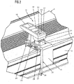
- eine perspektivische Darstellung des Übertragungsorgans der Anordnung gemäß
Fig. 1 und - Figur 3
- eine Explosionsdarstellung eines Einstellbügels der Anordnung gemäß
Fig. 1 undFig. 2 . - Anwendungsgebiet der Erfindung sind Jalousien oder Raffstores. Der nachstehend beschriebenen Zeichnung liegt ein Raffstore zugrunde. Der grundsätzliche Aufbau und Wirkungsweise derartiger Anordnungen sind an sich bekannt und sind daher nachstehend nur erwähnt, soweit sie für das Verständnis der Erfindung von Bedeutung sein können.
- Der in
Fig. 1 dargestellte Raffstore enthält einen durch parallel übereinander angeordnete Lamellen 1 und eine untere Endschiene 2 gebildeten, heb- und senkbaren Behang 3, der im dargestellten, hoch gezogenen Zustand ein Lamellenpaket bildet und über einen unteren Durchlassschlitz in ein im Bereich des oberen Rands einer zu verschattenden Gebäudeöffnung anbringbares, kastenförmiges Gehäuse 4 eingefahren ist, von dessen seitlichen Enden dem Behang 3 zugeordnete Führungsschienen 5 nach unten abgehen können, in welche die Lamellen 1 und die Endschiene 2 mit nicht näher dargestellten, seitlichen Führungsnippeln eingreifen können. Das Gehäuse 4 kann aus mehreren, an ihren aneinander zugewandten Enden ineinander eingehängten Teilen bestehen. - Zum Heben und Senken des Behangs 3 und zum Wenden der Lamellen 1 um eine zu ihrer Längsrichtung parallele Achse sind mehrere, über die Länge der Lamellen 1 verteilte, in
Fig. 1 lediglich durch unterbrochene Linien angedeutete Hubbänder 6 und Wendebänder 7 vorgesehen. Die Hubbänder 6 sind durch zugeordnete Ausnehmungen der Lamellen 1 durchgeführt und greifen an der Endschiene 2 an. Über die Hubbänder 6 ist der Behang 3 an oberen Tragorganen 8 aufgehängt, die mit ihren Enden auf zugeordneten Haltern der oberen Gehäusewand aufliegen können. Die Wendebänder 7 greifen an wenigstens einer Längsseite, hier an beiden Längsseiten der Lamellen 1 an bzw. wirken nach Art einer Leiter hiermit zusammen. - Zur Betätigung der Hubbänder 6 und Wendebänder 7, die durch nicht näher dargestellte Umlenkorgane, die im Bereich der Tragorgane 8 vorgesehen sein können, umgelenkt werden, ist eine in zur Behangebene lotrechter Richtung neben dem durch den hochgezogenen Behang 3 gebildeten Lamellenstapel angeordnete, also gegenüber dem Lamellenstapel seitlich versetzte Antriebseinheit 9 vorgesehen. Diese enthält eine über die Länge des Behangs 3 sich erstreckende, mittels eines zugeordneten Elektromotors 10 antreibbare Wickelwelle 11 zur Betätigung nicht näher dargestellter Wickelelemente für die Hubbänder 6 und Wendegetriebe für die Wendebänder 7. Die genannten Elemente der Antriebseinrichtung 9 sind in einer über die Länge der Antriebseinrichtung 9 durchgehenden Kopfleiste 12 in Form einer nach unten offenen, U-förmigen Profilschiene aufgenommen, die an einen nach unten abstehenden Arm 13 der Trageorgane 8 befestigt sein kann.
- Der Elektromotor 10 ist mit einem als Pilztaster ausgebildeten Aus-Schalter 14 versehen, der durch den Behang 3 beim Erreichen seiner der
Fig. 1 zugrunde liegenden zu einem Lamellenstapel hochgezogenen Endlage betätigbar ist, so dass sich praktisch eine automatische Endabschaltung ergibt. Hierzu ist ein eine die Schaltbewegung übertragendes Übertragungsorgan 15 vorgesehen, an das der Behang 3 beim Erreichen seiner oberen Endlage anläuft und das in Folge dessen den Aus-Schalter 14 betätigt. - Der Elektromotor 10 ist erfindungsgemäß so in der Kopfleiste 12 platziert, dass sein von einer Seite abstehender Aus-Schalter 14 nach oben weist. Der den Aus-Schalter 14 bildende Pilztaster überragt die Kopfleiste 12, die im Bereich ihres oberen Stegs mit einer dem den Aus-Schalter 14 bildenden Pilztaster zugeordneten Ausnehmung versehen ist, durch welche der den Aus-Schalter 14 bildende Pilztaster hindurchragen kann.
- Das Übertragungsorgan 15 ist als auf die Kopfleiste 12 aufgesetzte Wippe mit zwei gegenläufig voneinander weg gerichteten Armen 16, 17 ausgebildet. Die Wippe ist so platziert, dass sie mit ihrem Arm 16 den Behang 3 übergreift und mit ihrem Arm 17 den Aus-Schalter 14 des Elektromotors 10. Die genannte Wippe fungiert damit als Endschalter, der den Elektromotor 10 ausschaltet, so bald der Behang 3 die gewünschte obere Endlage erreicht hat.
- Zur Aufnahme der das Übertragungsorgan 15 bildenden Wippe ist auf die Oberseite der Kopfleiste 12 ein Lagerbock 18 aufgesetzt, auf dem die Wippe schwenkbar gelagert ist. Die Lagerung der zweiarmigen Wippe auf dem Lagerbock 18 ist als Schnappverbindung ausgebildet. Hierzu sind der Lagerbock 18 und die zweiarmige Wippe mit mit Drehfreiheitsgrad ineinander einschnappbaren Lagerelementen versehen.
- Der Lagerbock 18 ist an einem auf die Kopfleiste 12 aufgeklippsten, diese von oben umfassenden, U-förmigen Haltebügel 19 angebracht. Die unteren Enden der seitlichen Schenkel des Haltebügels 19 sind als die unteren Enden der Seitenwände der Kopfleiste 12 umfassende Federklauen ausgebildet. Der Haltebügel 19 wird wie der obere Steg der Kopfleiste 12 vom den Aus-Schalter 14 bildenden Pilztaster durchsetzt und ist hierzu gemäß
Fig. 2 mit einer deckend über der oben bereits erwähnten dem Pilztaster zugeordneten Ausnehmung des oberen Stegs der Kopfleiste 12 angeordneten Durchführausnehmung 20 versehen. - Die für Verwendungen vorliegender Art geeigneten Elektromotoren unterschiedlicher Hersteller haben erfahrungsgemäß unterschiedlich hohe Pilztaster zur Bildung eines Aus-Schalters 14. Deshalb ist an der Unterseite dem Aus-Schalter 14 zugeordneten Arms 17 der Wippe eine auswechselbare Ausgleichsplatte 21 anbringbar. Je nach verwendetem Motor können unterschiedliche Ausgleichsplatten 21 angebracht werden, womit eine universelle Verwendbarkeit erreicht wird. Die Ausgleichsplatte 21 ist lösbar am zugeordneten Arm 17 der Wippe festlegbar. Im dargestellten Beispiel ist hierzu eine Rastverbindung vorgesehen, die einerseits zwei mit Rastzähnen versehene Federschenkel 22 aufweisten, welche auf einen andererseits vorgesehenen Steg 23 aufrastbar sind.
- Bei manchen Anwendungen sind die gewünschten Endlagen des Behangs 3 am Elektromotor 10 einstellbar und fungiert daher die das Übertragungsorgan 15 bildende Wippe lediglich als Notaus-Schalter. Eine derartige Ausführung liegt der
Fig. 2 zugrunde. Dabei ist der Elektromotor 10 mit dem seinen Aus-Schalter 14 bildenden Pilztaster benachbarten, bezüglich der Breite der Kopfleiste 12 seitlich gegeneinander versetzten Schaltknöpfen 24 zur Einstellung der oben und uneren Endlage des Behangs 3 versehen. Diese befinden sich neben dem Haltebügel 19 und sind über eine Ausnehmung 25 des oberen Stegs der Kopfleiste 12 von oben zugänglich. Bei dieser Ausnehmung 25 kann es sich um eine größere, dem den Aus-Schalter 14 bildenden Pilztaster und den Schaltknöpfen 24 gemeinsam zugeordnete Ausnehmung 25 handeln. - Da die Schaltknöpfe 24 wie der den Aus-Schalter 14 bildende Pilztaster nach oben weisen, aber von unten über eine Revisionsöffnung des Gehäuses 4 etc. betätigbar sein sollen, ist zur Betätigung der Schaltknöpfe 24 ein die Kopfleiste 12 von oben übergreifender, U-förmiger Einstellbügel 26 vorgesehen, dessen untere Enden von unten erreichbar sind. Der Einstellbügel 26 ist in Flucht mit den Schaltknöpfen 24 auf die Kopfleiste 12 aufgeklippt. Und hierzu an den unteren Enden seiner Seitenschenkel auf die unteren Enden der Seitenwände der Kopfleiste 12 aufrastbaren, vorzugsweise als elastische Federklauen ausgebildeten Rastelementen 27 versehen. Von diesen können Betätigungslaschen 28 nach unten abgehen, die direkt von Hand oder mittels eines Werkzeugs ergriffen werden können. Der obere Steg des Betätigungsbügels 26 ist mit den Schaltknöpfen 24 zugeordneten Tastvorsprüngen 29 versehen. Je nachdem, an welcher Betätigungslasche 28 gezogen wird, wird der eine oder andere Schaltknopf 24 betätigt.
- Um dabei eine eindeutige Zuordnung der Seiten des Betätigungsbügels 26 zu den Schaltknöpfen 24 und damit eine hohe Bedienungssicherheit zu gewährleisten, sind die seitlichen Schenkel des Betätigungsbügels 26 mit einem gut erkennbaren Unterscheidungsmerkmal ausgestattet. Die Schaltknöpfe 24 sind in der Regel unterschiedlich eingefärbt. Als sehr sinnfälliges Unterscheidungsmerkmal sind daher zumindest die Betätigungslaschen 28 des Einstellbügels 26 ebenfalls unterschiedlich, vorzugsweise in den selben Farben wie die Schaltknöpfe 24 eingefärbt.
- Hierzu kann der Einstellbügel 26, wie aus
Fig. 3 erkennbar ist, aus zwei symmetrischen, unterschiedlich eingefärbten Hälften 26a,26b bestehen, die im Bereich des oberen Stegs einander überlappen und zusammen geklippst werden können. Hierzu sind die beiden Hälften 26a,26b mit ineinander einrastbaren Verbindungselementen 30 versehen. - Vorstehend ist zwar eine besonderst bevorzugte Ausführung der Erfindung näher erläutert. Abwandlungen und Modifikationen dieser Ausführung sind jedoch möglich, ohne den Rahmen der Erfindung zu verlassen.
Claims (15)
- Vorrichtung zum Beschatten einer Gebäudeöffnung etc., insbesondere Raffstore, mit einem aus parallel übereinander angeordneten Lamellen (1) und einer unteren Endschiene (2) bestehenden Behang (3), wobei die Lamellen (1) durch eine Anzahl von an der Endschiene (2) angreifenden Hubbänder (6) zu einem Lamellenstapel hochziehbar und nach unten ablassbar oder/und durch eine Anzahl von an Längsseiten der Lamellen (1) angreifenden Wendebändern (7) um eine längsseiten parallele Achse schwenkbar sind, und mit einer eine mittels eines Elektromotors (10) antreibbare Wickelwelle (11) enthaltenden Antriebseinheit (9) zur Betätigung der Hubbänder (6) oder/und der Wendebänder (7), wobei die Antriebseinheit (9) quer zur Behangebene neben dem Lamellenstapel angeordnet ist und dem Elektromotor (11) ein Aus-Schalter 14 zugeordnet, der mittels eines Übertragungsorgans (15) betätigbar ist, an dem der Behang (3) beim Erreichen seiner zu einem Lamellenstapel hoch gezogenen Endlage anläuft, dadurch gekennzeichnet, dass der Elektromotor (10) der Antriebseinrichtung (9) mit nach oben weisendem Aus-Schalter (14) angeordnet ist und dass das Übertragungsorgan (15) als darüber angeordnete, zweiarmige Wippe ausgebildet ist, die mit einem Arm (16) den Behang (3) und mit dem anderen Arm (17) den Aus-Schalter (14) des Elektromotors (10) übergreift.
- Vorrichtung nach Anspruch 1, dadurch gekennzeichnet, dass zur Aufnahme des Behangs (3) und der daneben angeordneten Antriebseinrichtung (9) ein Gehäuse (4) vorgesehen ist, das obere Tragorgane (8) und einen unteren Durchlaufschlitz für den Behang (3) aufweist und im welchem eine die Antriebseinrichtung (9) aufnehmende, durch eine nach unten offene Profilschiene gebildete Kopfleiste (12) befestigt ist.
- Vorrichtung nach Anspruch 2, dadurch gekennzeichnet, dass der Aus-Schalter (14) des Elektromotors (10) als Pilztaster ausgebildet ist, der den oberen Steg der Kopfleiste (12) durchgreift.
- Vorrichtung nach einem der vorhergehenden Ansprüche, dadurch gekennzeichnet, dass die das Übertragungsorgan (15) bildende, zweiarmige Wippe auf einem auf die Kopfleiste (12) aufgesetzten Lagerbock (18) schwenkbar gelagert ist.
- Vorrichtung nach Anspruch 4, dadurch gekennzeichnet, dass die das Übertragungsorgan (15) bildende Wippe und der Lagerbock (18) mit mit Drehfreiheitsgrad ineinander einschnappbaren Lagerelementen versehen sind.
- Vorrichtung nach einem der vorhergehenden, dadurch gekennzeichnet, dass an der Unterseite des dem Aus-Schalter (14) zugeordneten Arms (17) der Wippe eine auswechselbare Ausgleichsplatte (21) lösbar festlegbar ist.
- Vorrichtung nach Anspruch 6, dadurch gekennzeichnet, dass die Ausgleichsplatte (21) mittels einer Rastverbindung am zugeordneten Arm (17) der Wippe festlegbar ist.
- Vorrichtung nach einem der vorhergehenden Ansprüche, dadurch gekennzeichnet, dass der Elektromotor (10) der Antriebseinrichtung (9) mit seinem Aus-Schalter (14) benachbarten Schaltknöfen (24) zur Einstellung der Endlagen des Behangs (3) versehen ist, die über eine zugeordnete Ausnehmung (25) des oberen Stegs der Kopfleiste (12) von oben zugänglich und mittels eines die Kopfleiste (12) von oben übergreifenden, U-förmigen Einstellbügels (26) von unten betätigbar sind.
- Vorrichtung nach Anspruch 8, dadurch gekennzeichnet, dass das der Einstellbügel (26) in Flucht mit den Schaltknöpfen (24) an den seitlichen Rändern der Kopfleiste (12) einklippsbar ist.
- Vorrichtung nach Anspruch 8 oder 9, dadurch gekennzeichnet, dass das der obere Steg des Einstellbügels (26) mit den Schaltknöpfen (24) zugeordneten Vorsprüngen (29) versehen ist
- Vorrichtung nach einem der vorhergehenden Ansprüche 8 bis 10, dadurch gekennzeichnet, dass die seitlichen Schenkel des Einstellbügels (26) mit unteren Grifflaschen (28) versehen sind.
- Vorrichtung nach einem der vorhergehenden Ansprüche 8 bis 11, dadurch gekennzeichnet, dass die seitlichen Schenkel des Einstellbügels (26) mit wenigstens einem Unterscheidungsmerkmal ausgestattet sind.
- Vorrichtung nach Anspruch 12, dadurch gekennzeichnet, dass die seitlichen Schenkel des Einstellbügels (26) vorzugsweise in den verschiedenen Farben der Schaltknöpfe (24) zumindest bereichsweise verschieden eingefärbt sind.
- Vorrichtung nach Anspruch 13, dadurch gekennzeichnet, dass der Einstellbügel (26) aus zwei symmetrischen, im Bereich seines oberen Stegs mit einander verbundenen Teilen (26a,26b) besteht, die unterschiedlich eingefärbt sind.
- Vorrichtung nach Anspruch 14, dadurch gekennzeichnet, dass die beiden Teile (26a,26b) des Einstellbügels (26) mit ineinander einrastbaren Verbindungselementen (31) versehen sind.
Applications Claiming Priority (1)
| Application Number | Priority Date | Filing Date | Title |
|---|---|---|---|
| DE202018000946.6U DE202018000946U1 (de) | 2018-02-22 | 2018-02-22 | Vorrichtung zum Beschatten einer Gebäudeöffnung |
Publications (2)
| Publication Number | Publication Date |
|---|---|
| EP3530867A1 true EP3530867A1 (de) | 2019-08-28 |
| EP3530867B1 EP3530867B1 (de) | 2021-03-10 |
Family
ID=61765597
Family Applications (1)
| Application Number | Title | Priority Date | Filing Date |
|---|---|---|---|
| EP19020029.5A Active EP3530867B1 (de) | 2018-02-22 | 2019-01-17 | Vorrichtung zum beschatten einer gebäudeöffnung |
Country Status (2)
| Country | Link |
|---|---|
| EP (1) | EP3530867B1 (de) |
| DE (1) | DE202018000946U1 (de) |
Citations (5)
| Publication number | Priority date | Publication date | Assignee | Title |
|---|---|---|---|---|
| DE2362112A1 (de) * | 1973-12-14 | 1975-06-26 | Germann Helmut | Anordnung eines endabschalters eines motors in rolladen oder jalousettenantrieben |
| JPS6044994U (ja) * | 1983-09-03 | 1985-03-29 | 立川ブラインド工業株式会社 | 電動ブラインドの上昇停止装置 |
| DE19652975A1 (de) * | 1996-12-19 | 1998-06-25 | Alsthom Cge Alcatel | Jalousieantrieb mit einem von außen betätigbaren Endschalter |
| DE202010013522U1 (de) | 2010-09-24 | 2010-12-09 | Roma Kg | Vorrichtung zum Beschatten einer Gebäudeöffnung |
| DE202016105975U1 (de) * | 2015-11-16 | 2016-12-08 | Schlotterer Sonnenschutz Systeme Gmbh | Beschattungsvorrichtung |
-
2018
- 2018-02-22 DE DE202018000946.6U patent/DE202018000946U1/de not_active Expired - Lifetime
-
2019
- 2019-01-17 EP EP19020029.5A patent/EP3530867B1/de active Active
Patent Citations (5)
| Publication number | Priority date | Publication date | Assignee | Title |
|---|---|---|---|---|
| DE2362112A1 (de) * | 1973-12-14 | 1975-06-26 | Germann Helmut | Anordnung eines endabschalters eines motors in rolladen oder jalousettenantrieben |
| JPS6044994U (ja) * | 1983-09-03 | 1985-03-29 | 立川ブラインド工業株式会社 | 電動ブラインドの上昇停止装置 |
| DE19652975A1 (de) * | 1996-12-19 | 1998-06-25 | Alsthom Cge Alcatel | Jalousieantrieb mit einem von außen betätigbaren Endschalter |
| DE202010013522U1 (de) | 2010-09-24 | 2010-12-09 | Roma Kg | Vorrichtung zum Beschatten einer Gebäudeöffnung |
| DE202016105975U1 (de) * | 2015-11-16 | 2016-12-08 | Schlotterer Sonnenschutz Systeme Gmbh | Beschattungsvorrichtung |
Also Published As
| Publication number | Publication date |
|---|---|
| DE202018000946U1 (de) | 2018-03-09 |
| EP3530867B1 (de) | 2021-03-10 |
Similar Documents
| Publication | Publication Date | Title |
|---|---|---|
| EP0228477B1 (de) | Raffbare Schutzvorrichtung | |
| EP0338362B1 (de) | Sonnenschutzeinrichtung | |
| DE2752432A1 (de) | Rolltor fuer hallen o.dgl. | |
| DE7529767U (de) | Stabbetaetigte jalousie | |
| DE102018205680A1 (de) | Wohnwagenfenster und Öffnungsmechanismus dafür | |
| EP2540951A1 (de) | Lamellenstore mit verwindbaren Lamellen | |
| DE2409934C2 (de) | Lamellenjalousie | |
| DE10316836B4 (de) | Elektrisch betätigbare Jalousie | |
| DE3415551A1 (de) | Rolladen fuer dachfenster | |
| DE2910717C2 (de) | Rolladen für trapez- oder dreieckförmige Fenster | |
| EP3530867B1 (de) | Vorrichtung zum beschatten einer gebäudeöffnung | |
| DE60119847T2 (de) | Manuelle Steuervorrichtung für den Elektromotor eines Rolladens | |
| DE19727379A1 (de) | Raffstore mit Wendeantrieb | |
| DE519972T1 (de) | Fensterjalousie oder vorhang, insbesondere für zweischeibenisolationsglasfenster. | |
| EP0254896A2 (de) | Rollo-Vorhang für Wohnwagenfenster | |
| AT410241B (de) | Rolladen | |
| DE202019000076U1 (de) | Rafflamellenstore mit Rettungsweg | |
| EP0887509A1 (de) | Sonnenschutzanlage mit horizontalen Lamellen | |
| DE102012203945A1 (de) | Horizontal-Jalousie | |
| DE2836037A1 (de) | Fensterheber | |
| EP4474610B1 (de) | Schutzvorrichtung für eine gebäudeöffnung und gebäudeöffnung mit einer solchen schutzvorrichtung | |
| DE10304898B4 (de) | Rollladen | |
| DE10349716B4 (de) | Hubtor | |
| EP0805252A2 (de) | Seilfensterheber mit vergrössertem Hub | |
| EP2920397B1 (de) | Führungsanordnung für einen behang |
Legal Events
| Date | Code | Title | Description |
|---|---|---|---|
| PUAI | Public reference made under article 153(3) epc to a published international application that has entered the european phase |
Free format text: ORIGINAL CODE: 0009012 |
|
| STAA | Information on the status of an ep patent application or granted ep patent |
Free format text: STATUS: THE APPLICATION HAS BEEN PUBLISHED |
|
| AK | Designated contracting states |
Kind code of ref document: A1 Designated state(s): AL AT BE BG CH CY CZ DE DK EE ES FI FR GB GR HR HU IE IS IT LI LT LU LV MC MK MT NL NO PL PT RO RS SE SI SK SM TR |
|
| AX | Request for extension of the european patent |
Extension state: BA ME |
|
| STAA | Information on the status of an ep patent application or granted ep patent |
Free format text: STATUS: REQUEST FOR EXAMINATION WAS MADE |
|
| 17P | Request for examination filed |
Effective date: 20200228 |
|
| RBV | Designated contracting states (corrected) |
Designated state(s): AL AT BE BG CH CY CZ DE DK EE ES FI FR GB GR HR HU IE IS IT LI LT LU LV MC MK MT NL NO PL PT RO RS SE SI SK SM TR |
|
| GRAP | Despatch of communication of intention to grant a patent |
Free format text: ORIGINAL CODE: EPIDOSNIGR1 |
|
| STAA | Information on the status of an ep patent application or granted ep patent |
Free format text: STATUS: GRANT OF PATENT IS INTENDED |
|
| INTG | Intention to grant announced |
Effective date: 20201027 |
|
| RIN1 | Information on inventor provided before grant (corrected) |
Inventor name: MAIER, WILFRIED |
|
| GRAS | Grant fee paid |
Free format text: ORIGINAL CODE: EPIDOSNIGR3 |
|
| GRAA | (expected) grant |
Free format text: ORIGINAL CODE: 0009210 |
|
| STAA | Information on the status of an ep patent application or granted ep patent |
Free format text: STATUS: THE PATENT HAS BEEN GRANTED |
|
| AK | Designated contracting states |
Kind code of ref document: B1 Designated state(s): AL AT BE BG CH CY CZ DE DK EE ES FI FR GB GR HR HU IE IS IT LI LT LU LV MC MK MT NL NO PL PT RO RS SE SI SK SM TR |
|
| REG | Reference to a national code |
Ref country code: GB Ref legal event code: FG4D Free format text: NOT ENGLISH |
|
| REG | Reference to a national code |
Ref country code: CH Ref legal event code: EP Ref country code: AT Ref legal event code: REF Ref document number: 1369989 Country of ref document: AT Kind code of ref document: T Effective date: 20210315 |
|
| REG | Reference to a national code |
Ref country code: DE Ref legal event code: R096 Ref document number: 502019000918 Country of ref document: DE |
|
| REG | Reference to a national code |
Ref country code: IE Ref legal event code: FG4D Free format text: LANGUAGE OF EP DOCUMENT: GERMAN |
|
| REG | Reference to a national code |
Ref country code: CH Ref legal event code: NV Representative=s name: PATENTANWAELTE MUNK, DE |
|
| REG | Reference to a national code |
Ref country code: LT Ref legal event code: MG9D |
|
| PG25 | Lapsed in a contracting state [announced via postgrant information from national office to epo] |
Ref country code: FI Free format text: LAPSE BECAUSE OF FAILURE TO SUBMIT A TRANSLATION OF THE DESCRIPTION OR TO PAY THE FEE WITHIN THE PRESCRIBED TIME-LIMIT Effective date: 20210310 Ref country code: HR Free format text: LAPSE BECAUSE OF FAILURE TO SUBMIT A TRANSLATION OF THE DESCRIPTION OR TO PAY THE FEE WITHIN THE PRESCRIBED TIME-LIMIT Effective date: 20210310 Ref country code: GR Free format text: LAPSE BECAUSE OF FAILURE TO SUBMIT A TRANSLATION OF THE DESCRIPTION OR TO PAY THE FEE WITHIN THE PRESCRIBED TIME-LIMIT Effective date: 20210611 Ref country code: BG Free format text: LAPSE BECAUSE OF FAILURE TO SUBMIT A TRANSLATION OF THE DESCRIPTION OR TO PAY THE FEE WITHIN THE PRESCRIBED TIME-LIMIT Effective date: 20210610 Ref country code: NO Free format text: LAPSE BECAUSE OF FAILURE TO SUBMIT A TRANSLATION OF THE DESCRIPTION OR TO PAY THE FEE WITHIN THE PRESCRIBED TIME-LIMIT Effective date: 20210610 Ref country code: LT Free format text: LAPSE BECAUSE OF FAILURE TO SUBMIT A TRANSLATION OF THE DESCRIPTION OR TO PAY THE FEE WITHIN THE PRESCRIBED TIME-LIMIT Effective date: 20210310 |
|
| REG | Reference to a national code |
Ref country code: NL Ref legal event code: MP Effective date: 20210310 |
|
| PG25 | Lapsed in a contracting state [announced via postgrant information from national office to epo] |
Ref country code: SE Free format text: LAPSE BECAUSE OF FAILURE TO SUBMIT A TRANSLATION OF THE DESCRIPTION OR TO PAY THE FEE WITHIN THE PRESCRIBED TIME-LIMIT Effective date: 20210310 Ref country code: RS Free format text: LAPSE BECAUSE OF FAILURE TO SUBMIT A TRANSLATION OF THE DESCRIPTION OR TO PAY THE FEE WITHIN THE PRESCRIBED TIME-LIMIT Effective date: 20210310 Ref country code: LV Free format text: LAPSE BECAUSE OF FAILURE TO SUBMIT A TRANSLATION OF THE DESCRIPTION OR TO PAY THE FEE WITHIN THE PRESCRIBED TIME-LIMIT Effective date: 20210310 |
|
| PG25 | Lapsed in a contracting state [announced via postgrant information from national office to epo] |
Ref country code: NL Free format text: LAPSE BECAUSE OF FAILURE TO SUBMIT A TRANSLATION OF THE DESCRIPTION OR TO PAY THE FEE WITHIN THE PRESCRIBED TIME-LIMIT Effective date: 20210310 |
|
| PG25 | Lapsed in a contracting state [announced via postgrant information from national office to epo] |
Ref country code: SM Free format text: LAPSE BECAUSE OF FAILURE TO SUBMIT A TRANSLATION OF THE DESCRIPTION OR TO PAY THE FEE WITHIN THE PRESCRIBED TIME-LIMIT Effective date: 20210310 Ref country code: EE Free format text: LAPSE BECAUSE OF FAILURE TO SUBMIT A TRANSLATION OF THE DESCRIPTION OR TO PAY THE FEE WITHIN THE PRESCRIBED TIME-LIMIT Effective date: 20210310 Ref country code: CZ Free format text: LAPSE BECAUSE OF FAILURE TO SUBMIT A TRANSLATION OF THE DESCRIPTION OR TO PAY THE FEE WITHIN THE PRESCRIBED TIME-LIMIT Effective date: 20210310 |
|
| PG25 | Lapsed in a contracting state [announced via postgrant information from national office to epo] |
Ref country code: IS Free format text: LAPSE BECAUSE OF FAILURE TO SUBMIT A TRANSLATION OF THE DESCRIPTION OR TO PAY THE FEE WITHIN THE PRESCRIBED TIME-LIMIT Effective date: 20210710 Ref country code: PL Free format text: LAPSE BECAUSE OF FAILURE TO SUBMIT A TRANSLATION OF THE DESCRIPTION OR TO PAY THE FEE WITHIN THE PRESCRIBED TIME-LIMIT Effective date: 20210310 Ref country code: SK Free format text: LAPSE BECAUSE OF FAILURE TO SUBMIT A TRANSLATION OF THE DESCRIPTION OR TO PAY THE FEE WITHIN THE PRESCRIBED TIME-LIMIT Effective date: 20210310 Ref country code: PT Free format text: LAPSE BECAUSE OF FAILURE TO SUBMIT A TRANSLATION OF THE DESCRIPTION OR TO PAY THE FEE WITHIN THE PRESCRIBED TIME-LIMIT Effective date: 20210712 Ref country code: RO Free format text: LAPSE BECAUSE OF FAILURE TO SUBMIT A TRANSLATION OF THE DESCRIPTION OR TO PAY THE FEE WITHIN THE PRESCRIBED TIME-LIMIT Effective date: 20210310 |
|
| REG | Reference to a national code |
Ref country code: DE Ref legal event code: R097 Ref document number: 502019000918 Country of ref document: DE |
|
| PLBE | No opposition filed within time limit |
Free format text: ORIGINAL CODE: 0009261 |
|
| STAA | Information on the status of an ep patent application or granted ep patent |
Free format text: STATUS: NO OPPOSITION FILED WITHIN TIME LIMIT |
|
| PG25 | Lapsed in a contracting state [announced via postgrant information from national office to epo] |
Ref country code: ES Free format text: LAPSE BECAUSE OF FAILURE TO SUBMIT A TRANSLATION OF THE DESCRIPTION OR TO PAY THE FEE WITHIN THE PRESCRIBED TIME-LIMIT Effective date: 20210310 Ref country code: DK Free format text: LAPSE BECAUSE OF FAILURE TO SUBMIT A TRANSLATION OF THE DESCRIPTION OR TO PAY THE FEE WITHIN THE PRESCRIBED TIME-LIMIT Effective date: 20210310 Ref country code: AL Free format text: LAPSE BECAUSE OF FAILURE TO SUBMIT A TRANSLATION OF THE DESCRIPTION OR TO PAY THE FEE WITHIN THE PRESCRIBED TIME-LIMIT Effective date: 20210310 |
|
| 26N | No opposition filed |
Effective date: 20211213 |
|
| PG25 | Lapsed in a contracting state [announced via postgrant information from national office to epo] |
Ref country code: SI Free format text: LAPSE BECAUSE OF FAILURE TO SUBMIT A TRANSLATION OF THE DESCRIPTION OR TO PAY THE FEE WITHIN THE PRESCRIBED TIME-LIMIT Effective date: 20210310 |
|
| PG25 | Lapsed in a contracting state [announced via postgrant information from national office to epo] |
Ref country code: IT Free format text: LAPSE BECAUSE OF FAILURE TO SUBMIT A TRANSLATION OF THE DESCRIPTION OR TO PAY THE FEE WITHIN THE PRESCRIBED TIME-LIMIT Effective date: 20210310 |
|
| PG25 | Lapsed in a contracting state [announced via postgrant information from national office to epo] |
Ref country code: IS Free format text: LAPSE BECAUSE OF FAILURE TO SUBMIT A TRANSLATION OF THE DESCRIPTION OR TO PAY THE FEE WITHIN THE PRESCRIBED TIME-LIMIT Effective date: 20210710 |
|
| PG25 | Lapsed in a contracting state [announced via postgrant information from national office to epo] |
Ref country code: MC Free format text: LAPSE BECAUSE OF FAILURE TO SUBMIT A TRANSLATION OF THE DESCRIPTION OR TO PAY THE FEE WITHIN THE PRESCRIBED TIME-LIMIT Effective date: 20210310 |
|
| REG | Reference to a national code |
Ref country code: BE Ref legal event code: MM Effective date: 20220131 |
|
| PG25 | Lapsed in a contracting state [announced via postgrant information from national office to epo] |
Ref country code: LU Free format text: LAPSE BECAUSE OF NON-PAYMENT OF DUE FEES Effective date: 20220117 |
|
| PG25 | Lapsed in a contracting state [announced via postgrant information from national office to epo] |
Ref country code: BE Free format text: LAPSE BECAUSE OF NON-PAYMENT OF DUE FEES Effective date: 20220131 |
|
| PG25 | Lapsed in a contracting state [announced via postgrant information from national office to epo] |
Ref country code: IE Free format text: LAPSE BECAUSE OF NON-PAYMENT OF DUE FEES Effective date: 20220117 |
|
| GBPC | Gb: european patent ceased through non-payment of renewal fee |
Effective date: 20230117 |
|
| PG25 | Lapsed in a contracting state [announced via postgrant information from national office to epo] |
Ref country code: GB Free format text: LAPSE BECAUSE OF NON-PAYMENT OF DUE FEES Effective date: 20230117 |
|
| PG25 | Lapsed in a contracting state [announced via postgrant information from national office to epo] |
Ref country code: MK Free format text: LAPSE BECAUSE OF FAILURE TO SUBMIT A TRANSLATION OF THE DESCRIPTION OR TO PAY THE FEE WITHIN THE PRESCRIBED TIME-LIMIT Effective date: 20210310 Ref country code: CY Free format text: LAPSE BECAUSE OF FAILURE TO SUBMIT A TRANSLATION OF THE DESCRIPTION OR TO PAY THE FEE WITHIN THE PRESCRIBED TIME-LIMIT Effective date: 20210310 |
|
| PG25 | Lapsed in a contracting state [announced via postgrant information from national office to epo] |
Ref country code: HU Free format text: LAPSE BECAUSE OF FAILURE TO SUBMIT A TRANSLATION OF THE DESCRIPTION OR TO PAY THE FEE WITHIN THE PRESCRIBED TIME-LIMIT; INVALID AB INITIO Effective date: 20190117 |
|
| PG25 | Lapsed in a contracting state [announced via postgrant information from national office to epo] |
Ref country code: MT Free format text: LAPSE BECAUSE OF FAILURE TO SUBMIT A TRANSLATION OF THE DESCRIPTION OR TO PAY THE FEE WITHIN THE PRESCRIBED TIME-LIMIT Effective date: 20210310 |
|
| PG25 | Lapsed in a contracting state [announced via postgrant information from national office to epo] |
Ref country code: TR Free format text: LAPSE BECAUSE OF FAILURE TO SUBMIT A TRANSLATION OF THE DESCRIPTION OR TO PAY THE FEE WITHIN THE PRESCRIBED TIME-LIMIT Effective date: 20210310 |
|
| REG | Reference to a national code |
Ref country code: CH Ref legal event code: U11 Free format text: ST27 STATUS EVENT CODE: U-0-0-U10-U11 (AS PROVIDED BY THE NATIONAL OFFICE) Effective date: 20260201 |
|
| PGFP | Annual fee paid to national office [announced via postgrant information from national office to epo] |
Ref country code: DE Payment date: 20260131 Year of fee payment: 8 |
|
| PGFP | Annual fee paid to national office [announced via postgrant information from national office to epo] |
Ref country code: AT Payment date: 20260119 Year of fee payment: 8 |
|
| PGFP | Annual fee paid to national office [announced via postgrant information from national office to epo] |
Ref country code: FR Payment date: 20260127 Year of fee payment: 8 |
|
| PGFP | Annual fee paid to national office [announced via postgrant information from national office to epo] |
Ref country code: CH Payment date: 20260201 Year of fee payment: 8 |