EP0228477B1 - Raffbare Schutzvorrichtung - Google Patents
Raffbare Schutzvorrichtung Download PDFInfo
- Publication number
- EP0228477B1 EP0228477B1 EP85116592A EP85116592A EP0228477B1 EP 0228477 B1 EP0228477 B1 EP 0228477B1 EP 85116592 A EP85116592 A EP 85116592A EP 85116592 A EP85116592 A EP 85116592A EP 0228477 B1 EP0228477 B1 EP 0228477B1
- Authority
- EP
- European Patent Office
- Prior art keywords
- protection device
- passage
- passages
- cords
- opens
- Prior art date
- Legal status (The legal status is an assumption and is not a legal conclusion. Google has not performed a legal analysis and makes no representation as to the accuracy of the status listed.)
- Expired
Links
Images


Classifications
-
- E—FIXED CONSTRUCTIONS
- E06—DOORS, WINDOWS, SHUTTERS, OR ROLLER BLINDS IN GENERAL; LADDERS
- E06B—FIXED OR MOVABLE CLOSURES FOR OPENINGS IN BUILDINGS, VEHICLES, FENCES OR LIKE ENCLOSURES IN GENERAL, e.g. DOORS, WINDOWS, BLINDS, GATES
- E06B9/00—Screening or protective devices for wall or similar openings, with or without operating or securing mechanisms; Closures of similar construction
- E06B9/24—Screens or other constructions affording protection against light, especially against sunshine; Similar screens for privacy or appearance; Slat blinds
- E06B9/26—Lamellar or like blinds, e.g. venetian blinds
- E06B9/28—Lamellar or like blinds, e.g. venetian blinds with horizontal lamellae, e.g. non-liftable
- E06B9/30—Lamellar or like blinds, e.g. venetian blinds with horizontal lamellae, e.g. non-liftable liftable
- E06B9/32—Operating, guiding, or securing devices therefor
- E06B9/327—Guides for raisable lamellar blinds with horizontal lamellae
-
- E—FIXED CONSTRUCTIONS
- E06—DOORS, WINDOWS, SHUTTERS, OR ROLLER BLINDS IN GENERAL; LADDERS
- E06B—FIXED OR MOVABLE CLOSURES FOR OPENINGS IN BUILDINGS, VEHICLES, FENCES OR LIKE ENCLOSURES IN GENERAL, e.g. DOORS, WINDOWS, BLINDS, GATES
- E06B9/00—Screening or protective devices for wall or similar openings, with or without operating or securing mechanisms; Closures of similar construction
- E06B9/24—Screens or other constructions affording protection against light, especially against sunshine; Similar screens for privacy or appearance; Slat blinds
- E06B9/26—Lamellar or like blinds, e.g. venetian blinds
- E06B9/28—Lamellar or like blinds, e.g. venetian blinds with horizontal lamellae, e.g. non-liftable
- E06B9/30—Lamellar or like blinds, e.g. venetian blinds with horizontal lamellae, e.g. non-liftable liftable
- E06B9/32—Operating, guiding, or securing devices therefor
- E06B9/322—Details of operating devices, e.g. pulleys, brakes, spring drums, drives
-
- E—FIXED CONSTRUCTIONS
- E06—DOORS, WINDOWS, SHUTTERS, OR ROLLER BLINDS IN GENERAL; LADDERS
- E06B—FIXED OR MOVABLE CLOSURES FOR OPENINGS IN BUILDINGS, VEHICLES, FENCES OR LIKE ENCLOSURES IN GENERAL, e.g. DOORS, WINDOWS, BLINDS, GATES
- E06B9/00—Screening or protective devices for wall or similar openings, with or without operating or securing mechanisms; Closures of similar construction
- E06B9/24—Screens or other constructions affording protection against light, especially against sunshine; Similar screens for privacy or appearance; Slat blinds
- E06B9/26—Lamellar or like blinds, e.g. venetian blinds
- E06B9/28—Lamellar or like blinds, e.g. venetian blinds with horizontal lamellae, e.g. non-liftable
- E06B9/30—Lamellar or like blinds, e.g. venetian blinds with horizontal lamellae, e.g. non-liftable liftable
- E06B9/32—Operating, guiding, or securing devices therefor
- E06B9/324—Cord-locks
Definitions
- the invention relates to a gatherable protective device with an upper head rail made of a hollow profile, with a raised and lowered lower bar, which closes the device downwards and which can be actuated for lifting and lowering, lateral profiles being fastened to the head rail by upper corner parts that run the cords.
- a wide variety of methods are known for actuating known blinds, each of these types of actuation requiring different guides for the pull cords.
- the known blinds are fixed to one or a maximum of two types of actuation, so that alternative types of actuation are not possible or require different construction parts.
- the object of the invention is to provide a protective device of the type mentioned, which allow the most varied types of actuation and the most varied guides of the pull cords.
- corner parts for the pull cords have a plurality of, at least partially in different directions, passage paths for the cords, all of which are connected to one another via a common space and each have a sliding surface for deflecting the pull cords.
- the pull cords can be led out on the upper corner part or, alternatively, on the lower foot part. They can also be operated using an operating handle in the side profile, or the bottom bar is moved directly by hand and only guided through the pull cords.
- Each of these types of actuation requires a wide variety of guides for the pull cords, all of which can be realized by the construction.
- the side profile can have two or more longitudinal channels and each have a passage path of the corner part opening into each of these channels. It is also proposed that in the corner part, as seen in the longitudinal direction of the headrail, there are mutually opposite passageways, one of which opens into the headrail. It is particularly advantageous if each of the opposite passageways forms several exit directions and has corresponding sliding surfaces. In this case, a passageway can emerge from the upper passageways, which opens at the front of the corner part.
- the passageways are formed by a separate molded part which is fastened inside the corner part.
- a molded part lying in the corner part can be made from particularly wear-resistant material, in particular even from plastic resistant to pull cord abrasion, so that the wear is low.
- two projections are formed on the top of the molded part, which form a U-shaped passage between them, in particular to the front. These upper projections ensure that the pull cords are securely guided and do not get tangled, and furthermore these projections form stops for the corner part.
- a simple and secure attachment of the molded part is achieved in that the molded part can be inserted into the side profile from above with an extension or a projection.
- a simple assembly and a large number of variations is achieved in that a foot part is fastened to the lower end of the side profiles, which has several passage ways for the pull cords.
- at least one passage can open into the interior of the side profile.
- the lateral profile has two longitudinal channels and one passage path of the foot part opens into each of these longitudinal channels.
- a passage way can open at the front of the foot part.
- a passage path can also open out on the side facing the window side rail.
- a passage path opens horizontally in the side facing the opposite corner part.
- the protective device can be a slatted blind, a folding blind, a folding curtain or a roller blind.
- the invention is described below with the aid of a slatted blind which, in comparison to other protective devices, has only one additional turning device for the slats:
- FIG. 1 is a slatted blind which can preferably be fastened on the inside of inclined, in particular also tiltable, roof windows.
- This has a cross-sectionally U-shaped horizontal head rail 1, from which ladder-shaped brackets 2 hang down from cords, which are indicated by dashed lines in FIG. 1 a and which hold the individual slats, not shown, at the required distance.
- a longitudinal shaft not shown, in the usual way, which can be rotated by a torsion bar 3 in order to turn the slats through the brackets 2.
- these corner parts 4 are inserted with their projections 5 (see FIGS. 2a and 2c), which enable a connection between the head rail 1 and side profiles 6.
- the lateral profiles 6 are fastened below the cuboid corner parts 4 and run downwards along both sides of the window, so that in the case of an oblique roof window, the profiles 6 are arranged obliquely in the same way parallel to the window bars.
- Both side profiles 6 each form a front and rear channel 6a, 6b through which the pull cords can run (Fig. 6). These channels are open over their entire length to the front or rear.
- Each corner part 4 has a hole 7 penetrating the corner part from the bottom upwards, which is oblique and thus not parallel to the profile 6 and into which a wood screw can be pushed in order to fasten the corner part 4 to the upper frame of the window.
- a molded part 8 which consists either of a metallic material or a plastic with high wear resistance to pull cord wear and forms the passage of the pull cords through the corner part 4.
- the molded part 8 On its underside, the molded part 8 has a projection 9 (FIGS. 3a-3c) which lies in the rear longitudinal channel 6b of the profile 6.
- the molded part 8 To form the passage paths, the molded part 8 has two downwardly extending channels 10, 11 (FIGS. 3c, 3d), which open into the longitudinal channels 6a, 6b of the profile 6.
- the channels 10, 11 start from a central area of the molded part 8 and from this area a further three passageways 12, 13, 14 start, of which the passageway 12 runs horizontally to the inside of the head rail 1 and the passageway 13 horizontally in the opposite direction outward.
- Fener begins in the central region of the molded part 8 a passage 14 which runs to the front of the corner part 4 and opens through an opening 15 of the corner part 4 (Fig. 2a).
- the passageways 10-14 are thus all connected to one another in the interior of the molded part 8 and thus also in the interior of the corner part 4 and run from this central region with two passageways 0.11 down into the channels of the profile 6, on both sides (passageways 12, 13) and forward (passage 14).
- curved sliding surfaces 16 are arranged as a transition between the through paths for deflecting the respective pull cord. Due to the many ways of connecting the passage paths, the molded part has a total of six sliding surfaces 16a-f. Due to the high sliding ability and wear resistance of the molded part, the pull cords can be pulled over these sliding surfaces without significant friction.
- the molded part 8 has on its upper side 2 molded projections 8a, 8b which extend upwards, between which the passage 14 runs and which, with their upper sides, form stops for the surface of the corner part 4. These projections 8a, 8b, with their approximately perpendicular longitudinal edges, form the sliding surfaces 16e, 16f.
- a foot part 17 with projections 18 is inserted into the longitudinal channels 6a, 6b.
- the foot part 17, similar to the corner part 4, has several passageways for the pull cords (FIGS. 4a-4e).
- the passageways 20, 21 running parallel to the profiles 6 lead to the inside of the foot part 17, from which Passage paths 22, 23 run to the side or to the front.
- the passage 22 leads in the direction of the opposite foot part. It is important that, in the same way as for the molded part 8, all the passageways are connected to one another via the inner cavity of the foot part 17, so that a pull cord entering the inside of the foot part through one of the passageways can exit through one of the other passageways.
- a frame profile (not shown) may also be provided at the height of the foot parts.
- a further passage 19 can also open out on the side facing the window side rail, in an area covered by the lateral profile.
- a slide 24 on which pull cords extending in the upward or downward direction can be fastened, which run in the rear channel 6b.
- a hollow pin 25 is fastened horizontally to the slide 24 and lies axially in the lower bar 26 of the blind.
- the end parts 27 attached to both ends of the lower bar 26 have openings 27a (FIGS. 7a-7b). Pull cords can run through these hollow bolts 25, which lie inside the lower bar 26 and, after exiting on the outer sides from the hollow pin 25, are deflected via sliding surfaces 28 of the slide 24 in the rear channel 6b of the profile 6 the circumferential pull cords can be set taut.
- a slide-shaped operating handle 30 is slidably mounted, which is pushed down by hand to move the lower bar 26 upwards, and which is pushed up to lower the lower bar.
- the handle 30 has an upper opening 30a in which two cords I, IV coming from above through the profile 6 are clamped and a lower opening 30b in which two cords 11, 111 coming from below through the profile 6 are clamped.
- the handle 30 can be clamped to the profile 6 by a barrier (rotary knob) 31, so that the lower bar is then also immovably fixed.
- the cords I-IV can be released, i.e. lie displaceably in the openings 30a, 30b of the handle 30 so that the bottom bar 26 can be moved up and down by alternately pulling on these cords.
- the cords I-IV can be threaded in various ways in the parts of the blind.
- One of the fastening and laying methods is described in the following, reference being made to FIGS. 1 and 1b: in particular, the end of this cord I, which lies in the rear channel 6b of the profile 6 and is fastened upward by this, is fastened to the right slide 24 is led.
- the right molded part 8 deflects the cord I to the head rail 1 and the cord 1 runs through the interior of the head rail 1 to the left molded part 8, which guides the cord I into the front channel 6a of the left profile 6. From the channel 6, the cord I arrives at the handle 30, to which it is attached or through which it can be pulled, in its clamped position.
- a cord IV is attached to the left carriage 24, in particular at the top, which is guided to the handle 30 via the rear channel 6b of the left profile 6, the left molded part 8 and the front channel 6a.
- the bottom bar 26 can be pulled up over the slide 24 when the handle is pushed down or the cords are pulled out of the handle to the front when it is fixed.
- Two further cords 11, 111, in particular fastened to the slide 24 or fastened to the springs 29, are fastened to the lower bar 26.
- the right cord II is guided down through the rear channel 6b of the right profile 6 to the right foot part 17, deflected by the latter into the side channel 6c of the profile, through the side channel 6c up to the right molded part 8, from there through the Head rail to the left molded part 8 and in the side channel 6c of the left profile 6 to the left foot part 17, which deflects the cord II upwards into the front channel 6a to the handle 30.
- a cord II is attached to the left spring 29 or slide 24, which enters via the left slide 24 into the rear channel 6b of the left profile 6, which leads it to the left foot part 17, which the cord III in the front channel 6a deflected upwards towards the handle.
- the molded parts 8, foot parts 17 and profiles 6 enable numerous other types of guidance and actuation of the blinds and cords.
- cords can emerge from one of the corner parts 4 or foot parts 17 for their actuation, and they can also cross through the lower bar 26.
- the slides 24 are slidably guided in the rear channels 6b and the cords emanating therefrom lie in these channels 6b in the first region, and that the handle 30 is slidably guided in one of the two front channels 6a and by it outgoing cords in the first area in these channels 6a.
Description
- Die Erfindung betrifft eine raffbare Schutzvorrichtung mit einer oberen Kopfschiene aus einem Hohlprofil, mit einer anheb- und absenkbaren Unterleiste, die die Vorrichtung nach unten abschliesst und die zum Heben und Senken betätigbar ist, wobei an der Kopfschiene durch obere Eckteile seitliche Profile befestigt sind, durch die die Schnüre laufen.
- Insbesondere zur Befestigung an der Innenseite von geneigten Dachfenstern ist es bekannt, z. B. Lamellenjalousien, anzuordnen, an deren oberere waagerechte Kopfschiene seitlich metallene Profile über Eckteile befestigt sind. Jede dieser seitlichen schräg verlaufenden Profile weist ein Hohlraum auf, in dem jeweils ein Schlitten geführt ist, die die Unterleiste tragen, siehe deutsches Gebrauchsmuster 81 10 574.
- Zur Betätigung bekannter Jalousien sind die unterschiedlichsten Methoden bekannt, wobei jede dieser Betätigungsarten unterschiedliche Führungen der Zugschnüre erfordern. Die bekannten Jalousien sind auf einen oder maximal zwei Betätigungsarten festgelegt, so dass alternative Betätigungsarten nicht möglich sind oder aber andere Konstruktionsteile erfordern.
- Aufgabe der Erfindung ist es, eine Schutzvorrichtung der eingangs genannten Art zu schaffen, die die unterschiedlichsten Betätigungsarten und die verschiedensten Führungen der Zugschnüre zulassen.
- Diese Aufgabe wird erfindungsgemäss dadurch gelöst, dass die Eckteile für die Zugschnüre mehrere, zumindest teilweise in verschiedene Richtungen weisende Durchtrittswege für die Schnüre aufweisen, die alle über einen gemeinsamen Raum miteinander verbunden sind und die zum Umlenken der Zugschnüre jeweils eine Gleitfläche aufweisen.
- Eine solche Konstruktion ermöglicht die verschiedensten Führungswege für die Zugschnüre, so dass insbesondere durch den Zusammenbau eine hohe Variabilität der Betätigung der Jalousie erreicht wird. Dies bedeutet nicht nur, dass nachträglich nach dem Einbau die Betätigungsart veränderbar ist, sondern dass auch die verschiedensten Jalousie- bzw. Rollovarianten angeboten und verkauft werden können ohne unterschiedliche Einzelteile zu benötigen. Unter Durchtrittswege werden die von den Schnüren zu folgenden Wege verstanden.
- So können die Zugschnüre zu ihrer Handhabung am oberen Eckteil oder alternativ am unteren Fussteil herausgeführt sein. Sie können aber auch durch einen im seitlichen Profil geführten Bedienungsgriff betätigt werden oder aber die Unterleiste wird direkt von Hand bewegt und nur durch die Zugschnüre geführt. Jede dieser Betätigungsarten erfordern unterschiedlichste Führungen der Zugschnüre, die alle durch die Konstruktion verwirklichbar sind.
- Hierbei ist es besonders vorteilhaft, wenn vom gemeinsamen Raum aus mehrere Durchtrittswege zur Kopfschiene und zum seitlichen Profil führen. Auch wird hierzu vorgeschlagen, dass mehrere vom gemeinsamen Raum zur freien Aussenseite führende Durchtrittswege vorgesehen sind.
- Von Vorteil ist es, wenn mindestens ein Durchtrittsweg in das Innere des seitlichen Profils mündet. Hierbei kann das seitliche Profil zwei oder mehrere Längskanäle aufweisen und in jeden dieser Kanäle je ein Durchtrittsweg des Eckteils münden. Auch wird vorgeschlagen, dass im Eckteil obere, in Kopfschienenlängsrichtung gesehen, einander gegenüberliegende Durchtrittswege vorgesehen sind, wovon jeweils einer in die Kopfschiene mündet. Besonders vorteilhaft ist es, wenn jeder der gegenüberliegenden Durchtrittswege mehrere Austrittrichtungen bildet und dementsprechende Gleitflächen aufweist. Hierbei kann von den oberen Durchtrittswegen ein Durchtrittsweg abgehen, der an der Vorderseite des Eckteils mündet.
- Von besonderem Vorteil ist es, wenn die Durchtrittswege von einem separaten Formteil gebildet sind, das im Innern des Eckteils befestigt ist. Ein solches im Eckteil einliegendes Formteil kann aus besonders verschleissfestem Material, insbesondere sogar aus gegenüber Zugschnurabrieb beständigen Kunststoff gefertigt sein, so dass die Abnutzung gering ist. Hierzu wird auch vorgeschlagen, dass an der Oberseite des Formteils zwei Vorsprünge angeformt sind, die zwischen sich einen U-förmigen Durchtrittsweg, insbesondere zur Vorderseite bilden. Diese oberen Vorsprünge stellen sicher, dass die Zugschnüre sicher geführt sind und nicht sich verheddern und ferner bilden diese Vorsprünge Anschläge für das Eckteil.
- Eine einfache und sichere Befestigung des Formteils wird dadurch erreicht, dass das Formteil mit einer Verlängerung oder einem Vorsprung von oben in das seitliche Profil einsteckbar ist.
- Eine einfache Montage und eine hohe Anzahl von Variationen wird dadurch erreicht, dass am unteren Ende der seitlichen Profile jeweils ein Fussteil befestigt ist, das mehrere Durchtrittswege für die Zugschnüre aufweist. Hierbei kann mindestens ein Durchtrittsweg in das Innere des seitlichen Profils münden. Auch wird hierzu vorgeschlagen, dass das seitliche Profil zwei Längskanäle aufweist und in jeden dieser Längskanäle je ein Durchtrittsweg des Fussteils mündet. Ferner kann ein Durchtrittsweg an der Vorderseite des Fussteils münden. Auch kann ein Durchtrittsweg an der dem Fensterseitenholm zugewandten Seite münden. In einer weiteren Alternative wird hierbei vorgeschlagen, dass ein Durchtrittsweg in der dem gegenüberliegenden Eckteil zugewandten Seite waagerecht mündet.
- In einer vorteilhaften Ausführung wird vorgeschlagen, dass die seitlichen Profile zwei Längskanäle bilden, von denen zumindest der hintere zur Rückseite hin über die gesamte Länge offen ist und dass in dem hinteren Längskanal ein Schlitten geführt ist, an dem die Unterleiste befestigt ist. Hierbei kann der Schlitten an deren Unterleiste über einen rohrförmigen Hohlbolzen befestigt sein, in dem eine Zugschnur einlegbar ist, die die Unterleiste durchquert oder daran festgelegt ist. Dies führt zu einer besonders einfachen und leicht zu montierenden Führung der Zugschnüre. Hierbei kann der Schlitten eine waagerechte Öffnung aufweisen, in die der Hohlbolzen steckbar ist und dass ein für die Zugschnüre vorgesehender Durchtrittsweg am oder im Schlitten mit der Öffnung verbunden ist. Ein Ausführungsbeispiel der Erfindung ist in den Zeichnungen dargestellt und wird im folgenden näher beschrieben. Es zeigen:
- Fig. 1 a eine perspektivische Darstellung einer Lamellenjalousie in teilweiser Durchsicht und bei fehlenden Lamellen,
- Fig. 1 b einen waagerechten Schnitt durch die Jalousie,
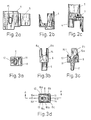
- Fig. 2a und b Seitenansichten des linken Eckteils,
- Fig. 2c eine Draufsicht auf das Eckteil,
- Fig. 3a eine Unteransicht des Formteils, das innerhalb des Eckteils befestigt ist,
- Fig. 3b Seitenansicht des Formteils,
- Fig. 3c einen Schnitt nach A-A in Fig. 3d,
- Fig. 3d eine Draufsicht auf das Formteil,
- Fig. 4a eine Unteransicht des linken Fussteils,
- Fig. 4b und c Seitenansicht des Fussteils,
- Fig. 4d einen Schnitt nach A-A in Fig. 4e,
- Fig. 4e eine Draufsicht auf das Fussteil,
- Fig. 5 eine perspektivische Ansicht des Schlittens,
- Fig. 5a eine Seitenansicht des Schlittens,
- Fig. 6 einen Schnitt durch ein seitliches Profil,
- Fig. 7a eine Seitenansicht eines auf beide Enden der Unterleiste steckbaren Endteils,
- Fig. 7b einen Schnitt nach A-A in Fig. 7a.
- Die Schutzvorrichtung kann eine Lamellenjalousie, Faltjalousie, ein Faltvorhang oder ein Rollo sein. Im folgenden wird die Erfindung anhand einer Lamellenjalousie beschrieben, die gegenüber anderen Schutzvorrichtungen nur eine zusätzliche Wendeeinrichtung für die Lamellen besitzt:
- Das in Fig. 1 dargestellte Ausführungsbeispiel ist eine vorzugsweise auf der Innenseite von schrägen, insbesondere auch kippbaren Dachfenstern befestigbare Lamellenjalousie. Diese weist eine im Querschnitt U-förmige waagerechte Kopfschiene 1 auf, von der leiterförmige Halterungen 2 aus Schnüren nach unten abhängen, die in Fig. 1 a gestrichtelt angedeutet sind und die die einzelnen nicht dargestellten Lamellen im erforderlichen Abstand halten. In der Kopfschiene 1 liegt in üblicher Weise eine nicht dargestellte Längswelle ein, die durch einen Drehstab 3 verdrehbar ist, um durch die Halterungen 2 die Lamellen zu wenden.
- Auf beiden Seiten der Kopfschiene 1 sind in diese Eckteile 4 mit ihren Vorsprüngen 5 (s. Fig. 2a und 2c) eingesteckt, die eine Verbindung zwischen der Kopfschiene 1 und seitlichen Profilen 6 ermöglichen. Die seitlichen Profile 6 sind unterhalb der quaderförmigen Eckteile 4 befestigt und laufen längs beider Fensterseiten nach unten, so dass bei einem schrägen Dachfenster die Profile 6 in gleicher Weise parallel zu den Fensterholmen schräg angeordnet sind.
- Beide seitlichen Profile 6 bilden jeweils einen vorderen und hinteren Kanal 6a, 6b, durch die die Zugschnüre laufen können (Fig. 6). Diese Kanäle sind über ihre gesamte Länge zur Vorder- bzw. Rückseite hin offen.
- Jedes Eckteil 4 besitzt eine das Eckteil von unten nach oben durchdringende Bohrung 7, die schräg und damit nicht parallel zum Profil 6 ist und in die eine Holzschraube schiebbar ist um das Eckteil 4 am oberen Rahmen des Fensters zu befestigen.
- Im Innenraum des hohlen Kunststoffeckteils 4 liegt ein Formteil 8 formschlüssig ein, das entweder aus einem metallischen Werkstoff oder einem Kunststoff hoher Verschleissfestigkeit gegenüber Zugschnurabrieb besteht und die Durchtrittswege der Zugschnüre durch das Eckteil 4 bildet. An seiner Unterseite weist das Formteil 8 einen Vorsprung 9 auf (Fig. 3a-3c), der in den hinteren Längskanal 6b des Profils 6 einliegt. Zur Bildung der Durchtrittswege weist das Formteil 8 zwei nach unten verlaufende Kanäle 10,11 auf (Fig. 3c, 3d), die in die Längskanäle 6a, 6b des Profils 6 münden. Die Kanäle 10,11 gehen von einem mittleren Bereich des Formteils 8 aus und von diesem Bereich gehen noch weitere drei Durchtrittswege 12, 13, 14 aus, von denen der Durchtrittsweg 12 waagerecht zum Inneren der Kopfschiene 1 verläuft und der Durchtrittsweg 13 in entgegengesetzter Richtung waagerecht nach aussen. Fener beginnt im mittleren Bereich des Formteils 8 ein Durchtrittsweg 14, der zur Vorderseite des Eckteils 4 verläuft und durch eine Öffnung 15 des Eckteils 4 mündet (Fig. 2a). Die Durchtrittswege 10-14 sind somit alle im Inneren des Formteils 8 und damit auch im Inneren des Eckteils4 miteinander verbunden und verlaufen von diesem mittleren Bereich mit zwei Durchtrittswegen 0,11 nach unten in die Kanäle des Profils 6, zu beiden Seiten (Durchtrittswege 12,13) und nach vorne (Durchtrittsweg 14). Da eine durch einen der Durchtrittswege in das Innere des Formteils 8 gelangende Zugschnur durch einen der anderen Durchtrittswege wieder austreten kann und diese Durchtrittswege zueinander im rechten Winkel liegen, sind für das Umlenken der jeweiligen Zugschnur gekrümmte Gleitflächen 16 als Übergang zwischen den Durchtrittswegen angeordnet. Aufgrund der vielen Verbindungsweisen zwischen den Durchtrittswegen weist das Formteil insgesamt sechs Gleitflächen 16a-f auf. Aufgrund der hohen Gleitfähigkeit und Verschleissfestigkeit des Formteils können die Zugschnüre über diese Gleitflächen ohne wesentliche Reibung gezogen werden.
- Das Formteil 8 weist an seiner Oberseite 2 angeformte Vorsprünge 8a, 8b auf, die sich nach oben erstrecken, zwischen denen der Durchtrittsweg 14 verläuft und die mit ihren Oberseiten Anschläge für die Oberfläche des Eckteils 4 bilden. Diese Vorsprünge 8a, 8b bilden mit ihren etwa senkrecht verlaufenden Längskanten die Gleitflächen 16e, 16f.
- An der Unterseite der Profile 6 ist jeweils ein Fussteil 17 mit Vorsprüngen 18, in die Längskanäle 6a, 6b eingesteckt. Das Fussteil 17 weist ähnlich dem Eckteil 4 mehrere Durchtrittswege für die Zugschnüre auf (Fig. 4a-4e). Die parallel zu den Profilen 6 verlaufenden Durchtrittswege 20, 21 führen zum Inneren des Fussteils 17, von dem Durchtrittswege 22, 23 zur Seite bzw. nach vorne verlaufen. Hierbei führt der Durchtrittsweg 22 in Richtung zum gegenüberliegenden Fussteil. Wichtig ist, dass in gleicher Weise wie beim Formteil 8 über den inneren Hohlraum des Fussteils 17 alle Durchtrittswege miteinander verbunden sind, so dass eine durch einen der Durchtrittswege in das Innere des Fussteils hereinkommende Zugschnur durch einen der anderen Durchtrittswege austreten kann. Zwischen den Fussteilen 17 kann eventuell zusätzlich noch ein nicht dargestelltes Rahmenprofil in Höhe der Fussteile vorgesehen werden. Auch kann ein weiterer Durchtrittsweg 19 an der dem Fensterseitenholm zugewandten Seite münden, in einem vom seitlichen Profil bedeckten Bereich.
- Im hinteren Längskanal 6b des Profils 6 liegt ein Schlitten 24 gleitend ein, an dem sich nach oben oder nach unten erstreckend Zugschnüre befestigt sein können, die im hinteren Kanal 6b laufen. Am Schlitten 24 ist ein Hohlbolzen 25 waagerecht befestigt, der axial in der Unterleiste 26 der Jalousie einliegt. Hierzu weisen die an beiden Enden der Unterleiste 26 aufgesteckten Endteile 27 Öffnungen 27a auf (Fig. 7a-7b). Durch diese Hohlbolzen 25 können Zugschnüre verlaufen, die im Inneren der Unterleiste 26 einliegen und nach Austreten auf den Aussenseiten aus den Hohlbolzen 25 über Gleitflächen 28 des Schlittens 24 umgelenkt werden im hinteren Kanal 6b des Profils 6. Durch gegebenenfalls in der Unterleiste 26 befindliche Zugfedern 29 können die umlaufenden Zugschnüre gespannt festgelegt werden.
- Im vorderen Längskanal 6a des linken Profils 6 ist ein schieberförmiger Bedienungsgriff 30 gleitend gelagert, der von Hand nach unten geschoben wird, um die Unterleiste 26 nach oben zu bewegen, und der nach oben geschoben wird, um die Unterleiste abzusenken. Der Griff 30 weist eine obere Öffnung 30a auf, in der zwei von oben durch das Profil 6 kommende Schnüre I, IV festgeklemmt sind und eine untere Öffnung 30b, in der zwei von unten durch das Profil 6 kommende Schnüre 11, 111 festgeklemmt sind. Der Griff 30 kann durch eine Schranke (Drehknopf) 31 an dem Profil 6 festgeklemmt werden, so dass dann auch die Unterleiste unverschieblich feststeht. Im festgeklemmten Zustand können die Schnüre I-IV gelöst werden, d.h. verschieblich in den Öffnungen 30a, 30b des Griffes 30 einliegen so dass durch abwechselndes Ziehen an diesen Schnüren die Unterleiste 26 auf-und abbewegbar ist.
- Die Schnüre I-IV können auf die unterschiedlichsten Arten in den Teilen der Jalousie eingefädelt sein. Eine der Befestigungs- und Verlegeweisen wird im folgenden beschrieben, wobei auf Fig. 1 und 1 b Bezug genommen wird: Am rechten Schlitten 24 ist insbesondere das Ende dieser Schnur I befestigt, die im hinteren Kanal 6b des Profils 6 einliegt und durch diesen nach oben geführt ist. Das rechte Formteil 8 lenkt die Schnur I zur Kopfschiene 1 um und die Schnur 1 läuft durch das Innere der Kopfschiene 1 zum linken Formteil 8, das die Schnur I in den vorderen Kanal 6a des linken Profils 6 leitet. Vom Kanal 6 gelangt die Schnur I zum Griff 30, an dem sie befestigt ist oder aber durch den sie, bei dessen festgeklemmter Stellung, ziehbar ist. In gleicher Weise ist am linken Schlitten 24, insbesondere oben eine Schnur IV befestigt, die über den hinteren Kanal 6b des linken Profils 6, das linke Formteil 8 und den vorderen Kanal 6a zum Griff 30 geführt wird. Durch beide Schnüre I, IV ist die Unterleiste 26 über die Schlitten 24 nach oben ziehbar, wenn der Griff nach unten geschoben wird oder aber die Schnüre aus dem Griff nach vorne herausgezogen werden, wenn dieser feststeht.
- An der Unterleiste 26 sind zwei weitere Schnüre 11, 111, insbesondere an dem Schlitten 24 befestigt oder an den Federn 29 befestigt. Die rechte Schnur II ist durch den hinteren Kanal 6b des rechten Profils 6 nach unten zum rechten Fussteil 17 geführt, von diesem in den seitlichen Kanal 6c des Profils umgelenkt, durch den seitlichen Kanal 6c nach oben geführt zum rechten Formteil 8, von dort durch die Kopfschiene zum linken Formteil 8 und in den seitlichen Kanal 6c des linken Profils 6 zum linken Fussteil 17, das die Schnur II in den vorderen Kanal 6a nach oben zum Griff 30 umlenkt. In gleicher Weise ist an der linken Feder 29 oder Schlitten 24 eine Schnur II befestigt, die über den linken Schlitten 24 in den hinteren Kanal 6b des linken Profils 6 eintritt, der sie zum linken Fussteil 17 führt, das die Schnur III in den vorderen Kanal 6a nach oben zum Griff hin umlenkt. Ein Ziehen an den Schnüren 11, 111 durch ein Bewegen des Griffes nach oben oder durch ein direktes Ziehen dieser Schnüre aus dem Griff heraus bei feststehendem Griff führt zu einem Absenken der Unterleiste 26.
- Die Formteile 8, Fussteile 17 und Profile 6 ermöglichen zahlreiche weitere Führungs- und Betätigungsarten der Jalousie und Schnüre. So können Schnüre zu ihrer Betätigung aus einem der Eckteile 4 oder Fussteile 17 austreten, und ferner können sie die Unterleiste 26 durchqueren.
- Von besonderer Bedeutung ist, dass die Schlitten 24 in den hinteren Kanälen 6b gleitend geführt sind und die vondort ausgehenden Schnüre im ersten Bereich in diesen Kanälen 6b einliegen, und dass der Griff 30 in einem der zwei vorderen Kanäle 6a gleitend geführt ist und die von ihm ausgehenden Schnüre im ersten Bereich in diesen Kanälen 6a einliegen.
Claims (16)
Priority Applications (14)
| Application Number | Priority Date | Filing Date | Title |
|---|---|---|---|
| EP85116592A EP0228477B1 (de) | 1985-12-27 | 1985-12-27 | Raffbare Schutzvorrichtung |
| DE8585116592T DE3568204D1 (en) | 1985-12-27 | 1985-12-27 | Contractible protection device |
| AT85116592T ATE40736T1 (de) | 1985-12-27 | 1985-12-27 | Raffbare schutzvorrichtung. |
| DE8600264U DE8600264U1 (de) | 1985-12-27 | 1986-01-08 | Von Hand betätigbarer Schieber für eine raffbare Schutzvorrichtung |
| EP86309415A EP0228198A3 (de) | 1985-12-27 | 1986-12-03 | Raffbare Abschirmvorrichtung |
| US06/940,140 US4807683A (en) | 1985-12-27 | 1986-12-10 | Retractable screen |
| AU66428/86A AU6642886A (en) | 1985-12-27 | 1986-12-11 | Venetian blind and the like pull-cord guide |
| AU66427/86A AU6642786A (en) | 1985-12-27 | 1986-12-11 | Venetian blind and the like pull-cord slide guide |
| CA000526263A CA1275037A (en) | 1985-12-27 | 1986-12-24 | Retractable screen |
| CA000526262A CA1275036A (en) | 1985-12-27 | 1986-12-24 | Retractable screen which can be gathered up |
| ES8603602A ES2002233A6 (es) | 1985-12-27 | 1986-12-26 | Dispositivo de proteccion plegable tal como una persiana de laminas una persiana plegable una cortina plegable o un enrollable |
| JP61315991A JPH07979B2 (ja) | 1985-12-27 | 1986-12-26 | 引込可能スクリーン |
| JP61315990A JPH0631498B2 (ja) | 1985-12-27 | 1986-12-26 | 引込可能ブラインド |
| US07/217,091 US4865108A (en) | 1985-12-27 | 1988-07-07 | Frame for a retractable blind |
Applications Claiming Priority (1)
| Application Number | Priority Date | Filing Date | Title |
|---|---|---|---|
| EP85116592A EP0228477B1 (de) | 1985-12-27 | 1985-12-27 | Raffbare Schutzvorrichtung |
Publications (2)
| Publication Number | Publication Date |
|---|---|
| EP0228477A1 EP0228477A1 (de) | 1987-07-15 |
| EP0228477B1 true EP0228477B1 (de) | 1989-02-08 |
Family
ID=8193976
Family Applications (1)
| Application Number | Title | Priority Date | Filing Date |
|---|---|---|---|
| EP85116592A Expired EP0228477B1 (de) | 1985-12-27 | 1985-12-27 | Raffbare Schutzvorrichtung |
Country Status (8)
| Country | Link |
|---|---|
| US (2) | US4807683A (de) |
| EP (1) | EP0228477B1 (de) |
| JP (1) | JPH0631498B2 (de) |
| AT (1) | ATE40736T1 (de) |
| AU (1) | AU6642886A (de) |
| CA (1) | CA1275036A (de) |
| DE (2) | DE3568204D1 (de) |
| ES (1) | ES2002233A6 (de) |
Cited By (2)
| Publication number | Priority date | Publication date | Assignee | Title |
|---|---|---|---|---|
| DE102005062995B3 (de) * | 2005-12-30 | 2007-05-16 | Warema Kunststofftechnik Und M | Befestigungssystem für Sonnenschutzanlagen |
| DE102006000964A1 (de) * | 2006-01-07 | 2007-07-12 | Warema Kunststofftechnik Und Maschinenbau Gmbh | Endkappe für Schienenprofil |
Families Citing this family (24)
| Publication number | Priority date | Publication date | Assignee | Title |
|---|---|---|---|---|
| EP0228198A3 (de) * | 1985-12-27 | 1987-10-07 | Hunter Douglas Industries B.V. | Raffbare Abschirmvorrichtung |
| EP0267303B1 (de) * | 1986-11-10 | 1989-04-05 | Hunter Douglas Industries B.V. | Fussteil für eine Seitenführung |
| US5125447A (en) * | 1991-02-04 | 1992-06-30 | Timothy Suggs | Safety device for window decoration cords |
| DE4418735C2 (de) * | 1994-05-28 | 1997-11-27 | Benthin Ag | Vorrichtung zur Handbetätigung einer Jalousie, vorzugsweise einer Vertikaljalousie |
| US5533559A (en) * | 1995-02-06 | 1996-07-09 | Judkins; Ren | Window shade assembly with hold down |
| US5709258A (en) * | 1996-05-02 | 1998-01-20 | Advanced Design Group, Llc | Safety arrangement for window blinds |
| WO2000031369A1 (en) * | 1998-11-20 | 2000-06-02 | Hai Tee Young | Window shading device |
| US20060278349A1 (en) * | 2005-06-14 | 2006-12-14 | Han-Sen Lee | Space adjusting self centering end cap |
| US7841376B2 (en) * | 2007-10-17 | 2010-11-30 | Whole Space Industries Ltd. | Window covering safety device |
| US8056601B2 (en) * | 2008-03-12 | 2011-11-15 | Lutron Electronics Co., Inc. | Self-contained tensioned roller shade system |
| US8113264B2 (en) * | 2008-03-12 | 2012-02-14 | Lutron Electronics Co., Inc. | Tensioned roller shade system having a conical, grooved spool |
| WO2010076820A1 (en) * | 2008-12-30 | 2010-07-08 | Pellini S.P.A. | Motorised blind kit |
| US8967226B2 (en) * | 2009-12-23 | 2015-03-03 | Safe-T-Shade | Architectural cover operating assembly |
| US8950463B2 (en) | 2009-12-23 | 2015-02-10 | Safe-T-Shade | Cordless coverings for architectural opening having cord enclosures with a swivel feature and methods of assembling such cord enclosures |
| US8763671B2 (en) * | 2009-12-23 | 2014-07-01 | Safe-T-Shade | Cordless covering for architectural opening |
| US9151110B2 (en) * | 2010-03-02 | 2015-10-06 | Safe-T-Shade | Cordless blind systems having cord enclosures with a swivel feature and methods of assembling such cord enclosures |
| US9187952B2 (en) | 2010-03-02 | 2015-11-17 | Safe-T-Shade | Cordless blind system and retro-fit method |
| US8540006B1 (en) | 2012-05-08 | 2013-09-24 | SAFE-T-SHADE, Inc. | Apparatuses, systems and methods for locking lift cords used to lift architectural opening coverings |
| US8708023B2 (en) * | 2012-09-26 | 2014-04-29 | Wen-Yu Wu | Cordless blind assembly |
| CH707200A2 (de) * | 2012-11-09 | 2014-05-15 | Beat Guhl | Führungsanordnung für einen Behang. |
| US9382756B2 (en) * | 2014-01-31 | 2016-07-05 | Lutron Electronics Co., Inc. | Cable guided shade system |
| US9719296B1 (en) | 2014-10-06 | 2017-08-01 | Safe-T-Shade | Apparatuses and systems for selectively locking lift cords used to lift architectural opening coverings |
| US11643864B2 (en) | 2018-01-23 | 2023-05-09 | Pella Corporation | Screen edge retention and screen rethreading features for a hidden screen assembly and a fenestration assembly |
| US20220162906A1 (en) * | 2020-11-24 | 2022-05-26 | Hunter Douglas Inc. | Stackable coverings with overpowered lift systems and related systems with hold-down brackets |
Family Cites Families (17)
| Publication number | Priority date | Publication date | Assignee | Title |
|---|---|---|---|---|
| US2389956A (en) * | 1944-11-27 | 1945-11-27 | Albert T Castilonia | Venetian blind |
| US2557978A (en) * | 1945-12-28 | 1951-06-26 | Elza L Krumm | Enclosed venetian blind |
| US2639766A (en) * | 1947-05-13 | 1953-05-26 | Raymond C Pratt | Closure structure |
| US2617480A (en) * | 1948-04-21 | 1952-11-11 | Robert H Swackhamer | Venetian blind |
| FR1258091A (fr) * | 1960-05-28 | 1961-04-07 | Jalousien Kaiser | Jalousie |
| DE6918975U (de) * | 1969-05-09 | 1969-12-11 | Hansa Metallwerke Ag | Einfassung fuer fensterjalousetten |
| US3795267A (en) * | 1970-01-28 | 1974-03-05 | Levolor Lorentzen Inc | Venetian blind |
| US4202395A (en) * | 1978-09-11 | 1980-05-13 | Sundberg-Ferar, Inc. | Adjustable shade construction |
| DE3037701A1 (de) * | 1980-10-06 | 1982-07-15 | Emil Schenker AG, 5012 Schönenwerd | Rafflamellenstore, rolladen o.dgl. |
| DE3037759A1 (de) * | 1980-10-06 | 1982-11-04 | Emil Schenker AG, 5012 Schönenwerd | Rafflamellenstore |
| DE8110574U1 (de) * | 1981-04-07 | 1981-10-01 | Hansa Metallwarengesellschaft Mbh Thiessen & Hager, 2000 Hamburg | Lamellenjalousie |
| JPS59160793U (ja) * | 1983-04-15 | 1984-10-27 | 今井 克己 | 建物開口部の開閉装置 |
| JPS59188295U (ja) * | 1983-05-31 | 1984-12-13 | 日本エルミンサツシ株式会社 | ロ−ルスクリ−ンを具えた二重ガラス障子 |
| US4557309A (en) * | 1983-08-24 | 1985-12-10 | Verosol Usa Inc. | Sun blind |
| US4673018A (en) * | 1984-11-13 | 1987-06-16 | Verosol Usa Inc. | Sun blind |
| US4679610A (en) * | 1986-01-31 | 1987-07-14 | Mike Spraggins | Modular window insert with collapsible shade |
| NL8600264A (nl) * | 1986-02-03 | 1987-09-01 | Jogema Holding | Verbindingsstelsel voor een groot aantal parallelle gelijksoortige apparaten. |
-
1985
- 1985-12-27 DE DE8585116592T patent/DE3568204D1/de not_active Expired
- 1985-12-27 EP EP85116592A patent/EP0228477B1/de not_active Expired
- 1985-12-27 AT AT85116592T patent/ATE40736T1/de not_active IP Right Cessation
-
1986
- 1986-01-08 DE DE8600264U patent/DE8600264U1/de not_active Expired
- 1986-12-10 US US06/940,140 patent/US4807683A/en not_active Expired - Fee Related
- 1986-12-11 AU AU66428/86A patent/AU6642886A/en not_active Abandoned
- 1986-12-24 CA CA000526262A patent/CA1275036A/en not_active Expired - Fee Related
- 1986-12-26 ES ES8603602A patent/ES2002233A6/es not_active Expired
- 1986-12-26 JP JP61315990A patent/JPH0631498B2/ja not_active Expired - Lifetime
-
1988
- 1988-07-07 US US07/217,091 patent/US4865108A/en not_active Expired - Fee Related
Cited By (2)
| Publication number | Priority date | Publication date | Assignee | Title |
|---|---|---|---|---|
| DE102005062995B3 (de) * | 2005-12-30 | 2007-05-16 | Warema Kunststofftechnik Und M | Befestigungssystem für Sonnenschutzanlagen |
| DE102006000964A1 (de) * | 2006-01-07 | 2007-07-12 | Warema Kunststofftechnik Und Maschinenbau Gmbh | Endkappe für Schienenprofil |
Also Published As
| Publication number | Publication date |
|---|---|
| US4807683A (en) | 1989-02-28 |
| US4865108A (en) | 1989-09-12 |
| ES2002233A6 (es) | 1988-07-16 |
| EP0228477A1 (de) | 1987-07-15 |
| DE3568204D1 (en) | 1989-03-16 |
| CA1275036A (en) | 1990-10-09 |
| AU6642886A (en) | 1987-07-02 |
| JPH0631498B2 (ja) | 1994-04-27 |
| DE8600264U1 (de) | 1986-04-03 |
| JPS62215788A (ja) | 1987-09-22 |
| ATE40736T1 (de) | 1989-02-15 |
Similar Documents
| Publication | Publication Date | Title |
|---|---|---|
| EP0228477B1 (de) | Raffbare Schutzvorrichtung | |
| EP0153558B1 (de) | Bauteilsatz zum Anfertigen einer Lamelle eines Lamellenstores | |
| EP0539788A1 (de) | Führungsstab für Fensterdekorationen oder Beschattungssysteme | |
| EP0956422B1 (de) | Verschlussvorrichtung für eine wandöffnung | |
| DE202005014043U1 (de) | Zugschnurlose Jalousienanordnung | |
| EP0218020B1 (de) | Ausstell-Schiebedach für Kraftfahrzeuge | |
| DE602005002055T2 (de) | Zurückziehbare Jalousie | |
| DE3611857A1 (de) | Abstandshalter fuer eine vertikaljalousie | |
| DE4020334C2 (de) | Wand- oder Dachelement mit einem rahmenartigen Traggestell und verschwenkbar gehalterten, plattenartigen Lamellen | |
| EP0639688B1 (de) | Vorhang für drei- oder mehreckige Flächen | |
| DE10154777A1 (de) | Schiebesystem zum Verschliessen und Freigeben einer Dachöffnung | |
| DE2651873A1 (de) | Rafflamellenjalousie mit seitenfuehrungsschienen | |
| EP0702126B1 (de) | Rolladen | |
| EP0599092B1 (de) | Zusammenfaltbarer Behang für eine Fenster- oder Türöffnung | |
| DE3115926C2 (de) | Rolladen für Dachfenster in Schwenkflügelbauweise | |
| DE3032003A1 (de) | Jalousie | |
| CH687472A5 (de) | Verriegelungsmechanik fuer Tueren und Tore. | |
| EP0693611B1 (de) | Faltenstore | |
| DE10123565C1 (de) | Lamellenfläche für ein Gebäude | |
| EP3530867B1 (de) | Vorrichtung zum beschatten einer gebäudeöffnung | |
| EP0267303B1 (de) | Fussteil für eine Seitenführung | |
| DE19817847A1 (de) | Faltstore mit Behangführung | |
| WO2007019929A1 (de) | Verschlussanordnung | |
| EP1342880A1 (de) | Streifenvorhang | |
| DE1683336A1 (de) | Lamellenvorhang |
Legal Events
| Date | Code | Title | Description |
|---|---|---|---|
| PUAI | Public reference made under article 153(3) epc to a published international application that has entered the european phase |
Free format text: ORIGINAL CODE: 0009012 |
|
| 17P | Request for examination filed |
Effective date: 19861112 |
|
| AK | Designated contracting states |
Kind code of ref document: A1 Designated state(s): AT BE DE FR GB IT NL SE |
|
| 17Q | First examination report despatched |
Effective date: 19871202 |
|
| ITF | It: translation for a ep patent filed |
Owner name: STUDIO ING. ALFREDO RAIMONDI |
|
| GRAA | (expected) grant |
Free format text: ORIGINAL CODE: 0009210 |
|
| AK | Designated contracting states |
Kind code of ref document: B1 Designated state(s): AT BE DE FR GB IT NL SE |
|
| REF | Corresponds to: |
Ref document number: 40736 Country of ref document: AT Date of ref document: 19890215 Kind code of ref document: T |
|
| REF | Corresponds to: |
Ref document number: 3568204 Country of ref document: DE Date of ref document: 19890316 |
|
| GBT | Gb: translation of ep patent filed (gb section 77(6)(a)/1977) | ||
| ET | Fr: translation filed | ||
| PLBE | No opposition filed within time limit |
Free format text: ORIGINAL CODE: 0009261 |
|
| STAA | Information on the status of an ep patent application or granted ep patent |
Free format text: STATUS: NO OPPOSITION FILED WITHIN TIME LIMIT |
|
| 26N | No opposition filed | ||
| ITTA | It: last paid annual fee | ||
| PGFP | Annual fee paid to national office [announced via postgrant information from national office to epo] |
Ref country code: SE Payment date: 19931110 Year of fee payment: 9 |
|
| PGFP | Annual fee paid to national office [announced via postgrant information from national office to epo] |
Ref country code: FR Payment date: 19931209 Year of fee payment: 9 |
|
| PGFP | Annual fee paid to national office [announced via postgrant information from national office to epo] |
Ref country code: AT Payment date: 19931214 Year of fee payment: 9 |
|
| PGFP | Annual fee paid to national office [announced via postgrant information from national office to epo] |
Ref country code: GB Payment date: 19931217 Year of fee payment: 9 |
|
| PGFP | Annual fee paid to national office [announced via postgrant information from national office to epo] |
Ref country code: DE Payment date: 19931227 Year of fee payment: 9 |
|
| PGFP | Annual fee paid to national office [announced via postgrant information from national office to epo] |
Ref country code: NL Payment date: 19931231 Year of fee payment: 9 |
|
| PGFP | Annual fee paid to national office [announced via postgrant information from national office to epo] |
Ref country code: BE Payment date: 19940131 Year of fee payment: 9 |
|
| PG25 | Lapsed in a contracting state [announced via postgrant information from national office to epo] |
Ref country code: GB Effective date: 19941227 Ref country code: AT Effective date: 19941227 |
|
| PG25 | Lapsed in a contracting state [announced via postgrant information from national office to epo] |
Ref country code: SE Effective date: 19941228 |
|
| PG25 | Lapsed in a contracting state [announced via postgrant information from national office to epo] |
Ref country code: BE Effective date: 19941231 |
|
| EAL | Se: european patent in force in sweden |
Ref document number: 85116592.8 |
|
| BERE | Be: lapsed |
Owner name: HUNTER DOUGLAS INDUSTRIES B.V. Effective date: 19941231 |
|
| PG25 | Lapsed in a contracting state [announced via postgrant information from national office to epo] |
Ref country code: NL Effective date: 19950701 |
|
| GBPC | Gb: european patent ceased through non-payment of renewal fee |
Effective date: 19941227 |
|
| PG25 | Lapsed in a contracting state [announced via postgrant information from national office to epo] |
Ref country code: FR Effective date: 19950831 |
|
| NLV4 | Nl: lapsed or anulled due to non-payment of the annual fee |
Effective date: 19950701 |
|
| PG25 | Lapsed in a contracting state [announced via postgrant information from national office to epo] |
Ref country code: DE Effective date: 19950901 |
|
| EUG | Se: european patent has lapsed |
Ref document number: 85116592.8 |
|
| REG | Reference to a national code |
Ref country code: FR Ref legal event code: ST |