EP3530574B1 - Kartondichtungsvorrichtung - Google Patents
Kartondichtungsvorrichtung Download PDFInfo
- Publication number
- EP3530574B1 EP3530574B1 EP19159256.7A EP19159256A EP3530574B1 EP 3530574 B1 EP3530574 B1 EP 3530574B1 EP 19159256 A EP19159256 A EP 19159256A EP 3530574 B1 EP3530574 B1 EP 3530574B1
- Authority
- EP
- European Patent Office
- Prior art keywords
- flap
- folding
- sealing device
- case sealing
- cardboard box
- Prior art date
- Legal status (The legal status is an assumption and is not a legal conclusion. Google has not performed a legal analysis and makes no representation as to the accuracy of the status listed.)
- Active
Links
Images




Classifications
-
- B—PERFORMING OPERATIONS; TRANSPORTING
- B65—CONVEYING; PACKING; STORING; HANDLING THIN OR FILAMENTARY MATERIAL
- B65B—MACHINES, APPARATUS OR DEVICES FOR, OR METHODS OF, PACKAGING ARTICLES OR MATERIALS; UNPACKING
- B65B7/00—Closing containers or receptacles after filling
- B65B7/16—Closing semi-rigid or rigid containers or receptacles not deformed by, or not taking-up shape of, contents, e.g. boxes or cartons
- B65B7/20—Closing semi-rigid or rigid containers or receptacles not deformed by, or not taking-up shape of, contents, e.g. boxes or cartons by folding-down preformed flaps
-
- B—PERFORMING OPERATIONS; TRANSPORTING
- B31—MAKING ARTICLES OF PAPER, CARDBOARD OR MATERIAL WORKED IN A MANNER ANALOGOUS TO PAPER; WORKING PAPER, CARDBOARD OR MATERIAL WORKED IN A MANNER ANALOGOUS TO PAPER
- B31B—MAKING CONTAINERS OF PAPER, CARDBOARD OR MATERIAL WORKED IN A MANNER ANALOGOUS TO PAPER
- B31B50/00—Making rigid or semi-rigid containers, e.g. boxes or cartons
- B31B50/003—Straightening the side walls of boxes; Squaring collapsed folded box blanks; Deforming boxes
-
- B—PERFORMING OPERATIONS; TRANSPORTING
- B31—MAKING ARTICLES OF PAPER, CARDBOARD OR MATERIAL WORKED IN A MANNER ANALOGOUS TO PAPER; WORKING PAPER, CARDBOARD OR MATERIAL WORKED IN A MANNER ANALOGOUS TO PAPER
- B31B—MAKING CONTAINERS OF PAPER, CARDBOARD OR MATERIAL WORKED IN A MANNER ANALOGOUS TO PAPER
- B31B50/00—Making rigid or semi-rigid containers, e.g. boxes or cartons
- B31B50/02—Feeding or positioning sheets, blanks or webs
- B31B50/04—Feeding sheets or blanks
- B31B50/046—Feeding sheets or blanks involving changing orientation or changing direction of transport
-
- B—PERFORMING OPERATIONS; TRANSPORTING
- B31—MAKING ARTICLES OF PAPER, CARDBOARD OR MATERIAL WORKED IN A MANNER ANALOGOUS TO PAPER; WORKING PAPER, CARDBOARD OR MATERIAL WORKED IN A MANNER ANALOGOUS TO PAPER
- B31B—MAKING CONTAINERS OF PAPER, CARDBOARD OR MATERIAL WORKED IN A MANNER ANALOGOUS TO PAPER
- B31B50/00—Making rigid or semi-rigid containers, e.g. boxes or cartons
- B31B50/60—Uniting opposed surfaces or edges; Taping
- B31B50/72—Uniting opposed surfaces or edges; Taping by applying and securing strips or sheets
- B31B50/722—Uniting opposed surfaces or edges; Taping by applying and securing strips or sheets on already formed boxes
-
- B—PERFORMING OPERATIONS; TRANSPORTING
- B65—CONVEYING; PACKING; STORING; HANDLING THIN OR FILAMENTARY MATERIAL
- B65B—MACHINES, APPARATUS OR DEVICES FOR, OR METHODS OF, PACKAGING ARTICLES OR MATERIALS; UNPACKING
- B65B43/00—Forming, feeding, opening or setting-up containers or receptacles in association with packaging
- B65B43/08—Forming three-dimensional [3D] containers from sheet material
- B65B43/10—Forming three-dimensional [3D] containers from sheet material by folding the material
-
- B—PERFORMING OPERATIONS; TRANSPORTING
- B65—CONVEYING; PACKING; STORING; HANDLING THIN OR FILAMENTARY MATERIAL
- B65B—MACHINES, APPARATUS OR DEVICES FOR, OR METHODS OF, PACKAGING ARTICLES OR MATERIALS; UNPACKING
- B65B43/00—Forming, feeding, opening or setting-up containers or receptacles in association with packaging
- B65B43/12—Feeding flexible bags or carton blanks in flat or collapsed state; Feeding flat bags connected to form a series or chain
- B65B43/14—Feeding individual bags or carton blanks from piles or magazines
-
- B—PERFORMING OPERATIONS; TRANSPORTING
- B65—CONVEYING; PACKING; STORING; HANDLING THIN OR FILAMENTARY MATERIAL
- B65B—MACHINES, APPARATUS OR DEVICES FOR, OR METHODS OF, PACKAGING ARTICLES OR MATERIALS; UNPACKING
- B65B43/00—Forming, feeding, opening or setting-up containers or receptacles in association with packaging
- B65B43/26—Opening or distending bags; Opening, erecting, or setting-up boxes, cartons, or carton blanks
- B65B43/34—Opening or distending bags; Opening, erecting, or setting-up boxes, cartons, or carton blanks by internal pressure
-
- B—PERFORMING OPERATIONS; TRANSPORTING
- B65—CONVEYING; PACKING; STORING; HANDLING THIN OR FILAMENTARY MATERIAL
- B65B—MACHINES, APPARATUS OR DEVICES FOR, OR METHODS OF, PACKAGING ARTICLES OR MATERIALS; UNPACKING
- B65B5/00—Packaging individual articles in containers or receptacles, e.g. bags, sacks, boxes, cartons, cans, jars
- B65B5/02—Machines characterised by incorporation of means for making the containers or receptacles
-
- B—PERFORMING OPERATIONS; TRANSPORTING
- B65—CONVEYING; PACKING; STORING; HANDLING THIN OR FILAMENTARY MATERIAL
- B65B—MACHINES, APPARATUS OR DEVICES FOR, OR METHODS OF, PACKAGING ARTICLES OR MATERIALS; UNPACKING
- B65B7/00—Closing containers or receptacles after filling
- B65B7/16—Closing semi-rigid or rigid containers or receptacles not deformed by, or not taking-up shape of, contents, e.g. boxes or cartons
- B65B7/28—Closing semi-rigid or rigid containers or receptacles not deformed by, or not taking-up shape of, contents, e.g. boxes or cartons by applying separate preformed closures, e.g. lids, covers
- B65B7/2842—Securing closures on containers
- B65B7/2864—Securing closures on containers by adhesive tape
-
- B—PERFORMING OPERATIONS; TRANSPORTING
- B31—MAKING ARTICLES OF PAPER, CARDBOARD OR MATERIAL WORKED IN A MANNER ANALOGOUS TO PAPER; WORKING PAPER, CARDBOARD OR MATERIAL WORKED IN A MANNER ANALOGOUS TO PAPER
- B31B—MAKING CONTAINERS OF PAPER, CARDBOARD OR MATERIAL WORKED IN A MANNER ANALOGOUS TO PAPER
- B31B2100/00—Rigid or semi-rigid containers made by folding single-piece sheets, blanks or webs
- B31B2100/002—Rigid or semi-rigid containers made by folding single-piece sheets, blanks or webs characterised by the shape of the blank from which they are formed
- B31B2100/0022—Rigid or semi-rigid containers made by folding single-piece sheets, blanks or webs characterised by the shape of the blank from which they are formed made from tubular webs or blanks, including by tube or bottom forming operations
-
- B—PERFORMING OPERATIONS; TRANSPORTING
- B31—MAKING ARTICLES OF PAPER, CARDBOARD OR MATERIAL WORKED IN A MANNER ANALOGOUS TO PAPER; WORKING PAPER, CARDBOARD OR MATERIAL WORKED IN A MANNER ANALOGOUS TO PAPER
- B31B—MAKING CONTAINERS OF PAPER, CARDBOARD OR MATERIAL WORKED IN A MANNER ANALOGOUS TO PAPER
- B31B2110/00—Shape of rigid or semi-rigid containers
- B31B2110/30—Shape of rigid or semi-rigid containers having a polygonal cross section
- B31B2110/35—Shape of rigid or semi-rigid containers having a polygonal cross section rectangular, e.g. square
Definitions
- the present disclosure relates to a case sealing device.
- JP-A No. H06-171614 discloses a case sealing device where a first-approaching front flap comes into contact with and is folded by a member provided in a predetermined position, a rear flap is folded by a swinging member from behind, and, after the front and rear flaps have been folded, left and right flaps (extending along the conveyance direction) are folded by rod-shaped folding members.
- EP0542341A1 discloses a device that comprises a pair of symmetrical plates normally elastically kept in respective substantially vertical planes convergent in the direction of advancement of the boxes and suitable for rotating on respective convergent oblique axes under the action of the front edge of boxes of variable width until the side flaps of the boxes are closed.
- the rod-shaped folding members come into contact with and fold, simultaneously and parallel to, the left and right flaps, so there are cases where the rod-shaped folding members cannot fold the left and right flaps along the fold lines at the bases of the flaps.
- a case sealing device pertaining to a first aspect of the disclosure conveys cardboard boxes and at the same time closes a flap group provided on edges of openings of the cardboard boxes.
- the case sealing device includes folding members, a drive unit that moves the folding members, and a control unit that controls the drive unit.
- the folding members come into contact with flaps of the flap group that extend along the conveyance direction of the cardboard boxes and fold the flaps.
- longitudinal directions of the folding members are inclined with respect to the conveyance direction in such a way that the folding members come into contact with front-side front edges of the flaps in the conveyance direction before other portions of the flaps.
- the folding members can gradually fold the flaps from the front-side front edges of the flaps in the conveyance direction to the rear sides, so the flaps are reliably folded along their fold lines.
- a case sealing device pertaining to a second aspect of the disclosure is the case sealing device pertaining to the first aspect, wherein the folding members gradually descend after coming into contact with the front-side front edges of the flaps.
- the folding operation becomes an operation where the folding members fold the flaps from the upper portions of the flaps to the bases, so the flaps can be folded neatly as if they were folded by hand.
- a case sealing device pertaining to a third aspect of the disclosure is the case sealing device pertaining to the second aspect, wherein the folding members descend obliquely downward.
- sealing device in order to fold the flaps, an operation that knocks them down from the side and at the same time holds them down from above becomes necessary, so an operation where the folding members descend obliquely downward is sensical.
- a case sealing device pertaining to a fourth aspect of the disclosure is the case sealing device pertaining to the second aspect, wherein the folding members descend while revolving.
- sealing device in order to fold the flaps, an operation that knocks them down from the side and at the same time holds them down from above becomes necessary, and this operation can be realized by the folding members descending while revolving.
- a case sealing device pertaining to a fifth aspect of the disclosure is the case sealing device pertaining to any one of the second aspect to the fourth aspect, wherein the folding members are inclined with respect to the conveyance direction also when they are descending.
- the folding operation becomes an operation where the folding members fold the flaps from the upper portions of the flaps to the bases from the front of the flaps to the rear to completely fold the flaps, so the flaps can be folded neatly as if they were folded by hand.
- a case sealing device pertaining to a sixth aspect of the disclosure is the case sealing device pertaining to any one of the first aspect to the fifth aspect, wherein the angle of inclination of the longitudinal directions of the folding members with respect to the conveyance direction is in the range of 3° to 60°.
- a case sealing device pertaining to a seventh aspect of the disclosure is the case sealing device pertaining to any one of the first aspect to the sixth aspect, wherein the folding members are inclined with respect to a horizontal plane when they come into contact with the flaps.
- a case sealing device pertaining to an eighth aspect of the disclosure is the case sealing device pertaining to any one of the first aspect to the sixth aspect, wherein the folding members are provided for each of the flaps that extend along the conveyance direction.
- the folding members can gradually fold the flaps from the front-side front edges of the flaps in the conveyance direction to the rear sides, so the flaps are reliably folded along their fold lines.
- FIG. 1 is a block diagram of a packing system 1 equipped with a case sealing device pertaining to an embodiment of the disclosure. Furthermore, FIG. 2A is a perspective view showing the configuration of the packing system, and FIG. 2B is a perspective view showing a flow of cardboard boxes B and products G in the packing system 1.
- the packing system 1 is a system that packs a fixed number of bagged products (products G) such as snack foods, for example, in an aligned state and in multiple layers into cardboard boxes B.
- the packing system 1 comprises a cardboard box handling area DHA and a product handling area GHA that are interconnected in a state in which they are mutually independently separable.
- the cardboard box handling area DHA includes two processes, a case forming process P1 and a packing process P3.
- the product handling area GHA includes a product aligning process P2.
- the case forming process P1 is a process of erecting sheet-like cardboard box precursors Z into cardboard boxes B and conveying the cardboard boxes B to a packing position.
- the case forming process P1 is configured by a box precursor accommodating unit 11, a case forming unit 12, a first posture changing unit 13, and a box downward conveying unit 14.
- the product aligning process P2 is a process of feeding to a predetermined position the products G supplied from an upstream process, aligning a fixed number of the products G so that adjacent products partially lie on top of each other, and conveying the fixed number of products G to the packing position.
- the product aligning process P2 is configured by a product feeding unit 21, a product aligning unit 22, and a product inserting unit 23.
- the packing process P3 is a process of packing, into the cardboard boxes B that have been conveyed thereto from the case forming process PI, the fixed quantity of products G that have finished being aligned in the product aligning process P2, closing the boxes, and conveying the boxes to a box discharge position.
- the packing process P3 is configured by a product receiving unit 31, a second posture changing unit 32, and a case sealing unit 33.
- the packing system 1 performs multilayer packing of the products G into the cardboard boxes B, and the posture of the products G inside the boxes B is a "standing posture.” That is, the standing posture is a posture where, when the openings of the boxes B face up, the front sides and the back sides of the products G face sideways, the upper and lower end portions of the products G face up and down, and the left and right side portions of the products G face sideways.
- the cardboard box handling area DHA has a two-level structure, and the case forming process P1 and the packing process P3 are supported by a common frame 10.
- the case forming process P1 occupies the second-level portion, and the packing process P3 occupies the first-level portion.
- the conveyance direction of the cardboard boxes B from the erection of the cardboard boxes B by the case forming unit 12 to the box downward conveying unit 14 and the conveyance direction of the cardboard boxes B up to when the openings of the cardboard boxes B that have been packed with the products G are sealed by the case sealing unit 33 are mutually opposite directions.
- the case forming process P1 is configured by the box precursor accommodating unit 11 that introduces the cardboard box precursors Z to the packing system 1, the case forming unit 12 that erects the cardboard boxes B, the first posture changing unit 13 that rotates the cardboard boxes B by 90° about a horizontal axis orthogonal to the conveyance direction, and the box downward conveying unit 14 that conveys downward the cardboard boxes B that have been switched to a first posture.
- the box precursor accommodating unit 11 picks one at a time and transports upward the cardboard box precursor Z at the very front of the cardboard box precursors Z stacked in a supply position, rotates the transported cardboard box precursor Z by 90° about a vertical axis, and opens it into a tubular shape.
- the cardboard box precursors Z are placed in the supply position by a worker.
- the cardboard box precursors Z are collapsed with their flaps Zf open and are stacked in a horizontal direction in a posture in which the flaps Zf are positioned in the vertical direction.
- the flaps Zf on the top surface side will be called top flaps Zfa and the flaps Zf on the bottom surface side will be called bottom flaps Zfb.
- the upward transport of the cardboard box precursors Z is performed by a lift mechanism 111.
- a detection sensor (not shown in the drawings) sends a detection signal to a controller 40 (see FIG. 1 ).
- the rotation of the cardboard box precursors Z about the vertical axis is realized by sucking and holding, with suckers, the side surfaces of the cardboard box precursors Z with a sucking and rotating mechanism 112 and rotating the sucking and rotating mechanism 112 90° about the vertical axis.
- the case forming unit 12 conveys in a horizontal direction the cardboard box precursors Z that have been opened into a tubular shape and at the same time folds and tapes the bottom flaps Zfb of the cardboard box precursors Z to thereby erect the cardboard boxes B in a state in which the top flaps Zfa are open.
- the first posture changing unit 13 rotates the cardboard boxes B by 90° in the conveyance direction. More specifically, the first posture changing unit 13 rotates the cardboard boxes B by 90° about a horizontal axis orthogonal to the conveyance direction to thereby change the posture of the cardboard boxes B to a posture (hereinafter called a first posture) in which the openings and the top flaps Zfa of the cardboard boxes B are in the same vertical plane.
- a posture hereinafter called a first posture
- the openings face the product handling area GHA.
- the box downward conveying unit 14 conveys downward the cardboard boxes B that have been switched to the first posture. That is, the box downward conveying unit 14 moves the cardboard boxes B downward with the openings of the cardboard boxes B kept facing the product handling area GHA.
- a weigher Disposed upstream of the product aligning process P2 in terms of the flow of the products G in the packing system 1 are a weigher, a bag-making and packaging machine, and the like not shown in the drawings. Only products G that have passed, for example, weight, seal, and contamination inspections in the upstream process are supplied to the product aligning process P2 the packing system 1.
- the product aligning process P2 is configured by the product feeding unit 21 that accepts the products G and conveys them to a predetermined position, the product aligning unit 22 that aligns the products G supplied from the product feeding unit 21, and the product inserting unit 23 that accumulates and pushes out the aligned products G.
- the product feeding unit 21 has a product introducing conveyor 211 and a feeding conveyor 212.
- the product introducing conveyor 211 receives, downstream of the process that performs, for example, the weight, seal, and contamination inspections, the supply of the products G that have passed the inspections and leads those products G to the feeding conveyor 212.
- the feeding conveyor 212 conveys to the product aligning unit 22 the products G conveyed thereto from the product introducing conveyor 211.
- the product aligning unit 22 has a first aligning conveyor 221, a second aligning conveyor 222, and a third aligning conveyor 223.
- the product aligning unit 22 is a unit that conveys the products G to a predetermined position while performing an accumulating operation with respect to the products G.
- the product aligning unit 22 is particularly suited to the accumulation of bag packages, so it can also be used independently as a package accumulating device.
- the first aligning conveyor 22 in order to receive the products G that drop thereto from the feeding conveyor 212, has one end set in a lower position than the height of the distal end portion of the feeding conveyor 212 and has the other end set in the height position of the second aligning conveyor 222.
- the third aligning conveyor 223 conveys, in front of the openings of the cardboard boxes B standing by, the group of products G aligned by the first aligning conveyor 221 and the second aligning conveyor 222.
- the third aligning conveyor 223 doubles as an element of the product inserting unit 23 described below.
- the product inserting unit 23 sandwiches the front and rear of the group of products G aligned in a line by the third aligning conveyor 223 and inserts the whole group of products G into the cardboard boxes B. As shown in FIG. 2B , the product inserting unit 23 has a stand-up conveyor 231, a push-toward plate 233, and an insertion plate 235 in order to sandwich the aligned group of products G.
- the stand-up conveyor 231 is provided over the downstream end of the third aligning conveyor 223 and blocks the advance of the products G forming a line and being conveyed thereto.
- the stand-up conveyor 231 is disposed in such a way that its conveyance surface is always orthogonal to the conveyance direction of the products G.
- the conveyance surface of the stand-up conveyor 231 moves vertically upward a little before the products G come into contact with the conveyance surface of the stand-up conveyor 231. Then, when the leading end of the product G at the front comes into contact with the conveyance surface of the stand-up conveyor 231, an upward force acts on the leading end of the product G, and the horizontal movement of the product G by the third aligning conveyor 223 also continues, so the product G at the front can reliably stand up.
- the push-toward plate 233 pushes the product at the rear of the N-number of products G aligned in a line to thereby sandwich the products G between itself and the stand-up conveyor 231 and cause the products G to stand up.
- the push-toward plate 233 is provided on the upstream end side of the third aligning conveyor 223, but while the line of products G is moving from the second aligning conveyor 222 to the third aligning conveyor 223, the push-toward plate 233 is accommodated on the side of the third aligning conveyor 223 so that its flat surface portion is parallel to the conveyance direction of the products G. Furthermore, when the product G at the rear of the line has completely transferred from the second aligning conveyor 222 to the third aligning conveyor 223, the push-toward plate 233 swings so that its flat surface portion becomes orthogonal to the conveyance direction of the products G. Moreover, the push-toward plate 233 pushes the product G at the rear of the line to thereby push the entire line toward the stand-up conveyor 231.
- the conveyance surface of the stand-up conveyor 231 is moving vertically upward, so the product G at the front of the line stands up along the conveyance surface of the stand-up conveyor 231, and the next product G stands up along the product G at the front that has been made to stand up.
- the subsequent products G also successively stand up because of the same operation, so the N-number of products G become aligned in a standing state.
- the product inserting unit 23 collectively pushes, via the insertion plate 235, the N-number of products G in the standing state into the cardboard boxes B.
- the insertion plate 235 is positioned on the opposite side of the position of the cardboard boxes B across the third aligning conveyor 223.
- the open surfaces of the cardboard boxes B are positioned on the right side of the third aligning conveyor 223 and the insertion plate 235 is positioned on the left side of the third aligning conveyor 223.
- the insertion plate 235 stands by with its flat surface portion opposing the openings of the cardboard boxes B. After the N-number of products G have been switched to the standing state, the insertion plate 235 pushes the N-number of products G toward the open surfaces of the cardboard boxes B and in one fell swoop inserts the N-number of products G through the openings to the bottoms of the cardboard boxes B. The insertion plate 235 crosses between the stand-up conveyor 231 and the push-toward plate 233 and advances to the open surfaces of the cardboard boxes B.
- the packing process P3 has the product receiving unit 31 that receives the products G into the cardboard boxes B, the second posture changing unit 32 that changes the posture of the cardboard boxes so that the openings of the cardboard boxes face up, and the case sealing unit 33 that convey the cardboard boxes B that have finished being packed with the products G and at the same time closes the openings of the cardboard boxes B.
- the product receiving unit 31 maintains the cardboard boxes B in the first posture and has the cardboard boxes B stand by with the openings of the cardboard boxes B opposing the insertion plate 235 of the product inserting unit 23.
- the N-number of products G that have been switched to the standing state in the product inserting unit 23 are pushed out by the insertion plate 235 toward the open surfaces in the cardboard boxes B, so the product receiving unit 31 stands by in that position until the N-number of products G are completely inserted through the openings to the bottoms of the cardboard boxes B.
- the product receiving unit 31 descends a predetermined distance. Then, in order to receive a second layer of the N-number of products G, the product receiving unit 31 has the cardboard box B stand by in such a way that the portion of the opening of the cardboard box B that leads to the space above the first layer opposes the insertion plate 235.
- the product receiving unit 31 repeats the above-described operation so that an i-th layer of the N-number of products G is inserted into the cardboard box B, and the receiving of the products into the cardboard box B is finished.
- the second posture changing unit 32 has a posture changing mechanism 321 that changes the posture of the cardboard boxes B packed with the products G to a posture in which the openings face up.
- the posture changing mechanism 321 rotates the cardboard boxes B so that the open surfaces that had been vertical until then become horizontal, namely, so that the open surfaces face up.
- the posture changing mechanism 321 uses an L-shaped member with suckers that simultaneously suck the side surface and the bottom surface of the cardboard boxes B to hold the cardboard boxes B, and when the L-shaped member rotates by 90°, the cardboard boxes B rotate.
- the case sealing unit 33 has a discharge conveyor 330 that conveys the cardboard boxes B, a flap closing mechanism 340 (see FIG. 3A ) that closes the flaps around the openings of the cardboard boxes B, a side surface pushing mechanism 355 (see FIG. 4D ) that pushes the side surfaces of the cardboard boxes, and a tape applicator 380 that seals the openings closed by the flaps.
- the cardboard boxes B When the cardboard boxes B have been rotated by 90° with the posture changing mechanism 321, the cardboard boxes B are placed on the discharge conveyor 330 in a state in which the openings face up.
- the discharge conveyor 330 conveys the cardboard boxes B to the discharge position.
- FIG. 3A is a front view of the region around the flap closing mechanism 340 when a cardboard box B has not been conveyed thereto.
- FIG. 3B is a front view of the region around the flap closing mechanism 340 when a cardboard box B has been conveyed thereto.
- FIG. 3C is a front view of the region around the flap closing mechanism 340 as a rear flap Zfab is in the middle of being folded.
- FIG. 3D is a front view of the region around the flap closing mechanism 340 when folding bars 370a have descended to a lowest point.
- the flap closing mechanism 340 has a front flap folding member 350, a rear flap folding member 360, and left/right flap folding members 370.
- the cardboard box B is placed on the discharge conveyor 330 in such a way that its longitudinal direction is parallel to the conveyance direction, and, first, the front flap folding member 350 closes a front flap Zfaa positioned on the front edge of the opening as viewed from the conveyance direction.
- the rear flap folding member 360 closes a rear flap Zfab positioned on the rear edge of the opening as viewed from the conveyance direction.
- the left/right flap folding members 370 close a left flap Zfal and a right flap Zfar positioned on the left edge and the right edge of the opening as viewed from the conveyance direction.
- the left/right flap raising members 345 are a fixed pair of extension members and have a configuration where the distance that separates them increases heading outward and downward toward their distal ends.
- the left/right flap raising members 345 wait to receive at their two distal end portions the left flap Zfal and the right flap Zfar of the cardboard box B conveyed thereto, and after the front ends of the left flap Zfal and the right flap Zfar come into contact with the distal end portions, the front ends proceed along the left/right flap raising members 345, so the left flap Zfal and the right flap Zfar become scooped up and tilt inward closer to each other.
- the front flap folding member 350 has a first inclined surface 351, a second inclined surface 352, and a horizontal surface 353.
- the first inclined surface 351 is a surface inclined about 50° upward with respect to a horizontal plane.
- the second inclined surface 352 is a surface inclined about 15° upward with respect to a horizontal plane.
- the lower end of the first inclined surface 351 is connected to the upper end of the second inclined surface 352, and the lower end of the second inclined surface 352 is connected to one end of the horizontal surface 353.
- FIG. 4A shows the region around the flap closing mechanism 340 just before the front flap Zfaa of the cardboard box B comes into contact with the front flap folding member 350.
- FIG. 4B shows the region around the flap closing mechanism 340 when the front flap Zfaa of the cardboard box B is being folded by the front flap folding member 350.
- a side surface pushing mechanism that can push the side surface of the cardboard box B that is on the invisible side in FIG. 4A and FIG. 4B is provided.
- FIG. 4C is a perspective view of the region around the side surface pushing mechanism 355. Furthermore, FIG. 4D is a perspective view of the side surface pushing mechanism.
- a guide plate 331 that guides, along the discharge conveyor 330, the side surface of the lower portion of the cardboard box B that flows on the discharge conveyor 330 is provided on the side of the discharge conveyor 330, and the side surface pushing mechanism 355 is provided upstream of the guide plate 331 in the conveyance direction.
- the side surface pushing mechanism 355 includes a side surface pushing member 356, a side surface pushing air cylinder 357, and support shaft guides 358.
- the side surface pushing member 356 has a friction surface 356a.
- the friction surface 356a is normally positioned in the same plane as the guide plate 331.
- the side surface pushing air cylinder 357 has a piston 357a that is reciprocally moved by air pressure.
- the piston 357a is coupled to the opposite side of the friction surface 356a of the side surface pushing member 356 so that it can push out the friction surface 356a of the side surface pushing member 356 onto the conveyance surface of the discharge conveyor 330.
- the support shaft guides 358 each have a support shaft 358a and a bearing 358b.
- the support shafts 358a support the side surface pushing member 356 from the opposite side of the friction surface 356a.
- the bearings 358b guide the support shafts 358a along the moving direction of the piston 357a of the side surface pushing air cylinder 357.
- a total of two support shaft guides 358 are disposed one each on the left and right sides of the side surface pushing air cylinder 357.
- the side surface pushing mechanism 355 not only has the role of preventing uplift of the cardboard box B but also fulfills the function of preventing the cardboard box B from sliding forward when the rear flap is folded.
- the controller 40 causes the piston 357a of the side surface pushing air cylinder 357 to advance forward in the direction of the side surface of the cardboard box B so that a predetermined force acts with respect to the side surface pushing air cylinder 357.
- the predetermined force is set to an extent that does not hinder the conveyance of the cardboard box B and to an extent that the front or the back of the cardboard box B does not lift up, and about 20 N is preferred.
- a posture adjustment pushing mechanism 336 having the same mechanism as the side surface pushing mechanism 355 is disposed on the side of the discharge conveyor 330 and upstream of the side surface pushing mechanism 355.
- the posture adjustment pushing mechanism 336 pushes the side surface of the cardboard box B to thereby force the posture of the cardboard box B that has been rotated by 90° with the posture changing mechanism 321 and placed on the discharge conveyor 330 into a posture along the conveyance direction of the discharge conveyor 330.
- the rear flap folding member 360 folds the rear flap Zfab at the timing when the front flap Zfaa of the cardboard box B moves under the horizontal surface 353 of the front flap folding member 350.
- the rear flap folding member 360 is a member that is swung by an air cylinder 365.
- the rear flap folding member 360 has a hold-down plate 360a that is bent in a triangular shape and a transmission rod 360b that transmits the displacement of a piston of the air cylinder 365 to the hold-down plate 360a.
- the controller 40 When the controller 40 has judged that the front flap Zfaa of the cardboard box B has moved under the horizontal surface 353 of the front flap folding member 350, the controller 40 drives the air cylinder 365 to thereby cause the hold-down plate 360a to swing in a clockwise direction in the front view of FIG. 3C .
- the hold-down plate 360a swings while holding down the upper surface of the rear flap Zfab.
- the hold-down plate 360a has swung 90°, the rear flap Zfab becomes folded substantially horizontally.
- the left/right flap folding members 370 each have a folding bar 370a and two arms 370b.
- the folding bar 370a stands by in a higher position than the horizontal surface 353 of the front flap folding member 350.
- each arm 370b is coupled to the folding bar 370a. Furthermore, the arms 370b extend in such a way as to intersect the longitudinal direction of the folding bar 370a and to a higher position than the folding bar 370a. The other ends of the arms 370b are connected to a crankshaft 377 that is operated by a folding air cylinder 375.
- the left/right flap folding members 370 are disposed on the near side and the far side in the front views of FIG. 3A, FIG. 3B , and FIG. 3C and stand by with the leading ends of the folding bars 370a pointing upward and more outward than the trailing ends. That is, one folding bar 370a corresponds to each of the left flap Zfal and the right flap Zfar.
- FIG. 5 is a front view of the region around the flap closing mechanism 340 when the left flap Zfal of the cardboard box B is contacting the folding bar 370a.
- the longitudinal direction of the folding bar 370a is inclined with respect to the conveyance direction of the cardboard box B, so the front-side front edges of the left flap Zfal and the right flap Zfar come into contact with the folding bars 370a before any other part of the left flap Zfal and the right flap Zfar.
- the angle of inclination of the longitudinal direction of the folding bars 370a with respect to the conveyance direction is within the range of 3° to 60°, but preferably is 30°.
- the controller 40 operates the folding air cylinder 375 to thereby cause the folding bars 370a to descend while revolving.
- the folding bars 370a are inclined with respect to the conveyance direction also when they descend while revolving.
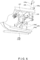
- FIG. 6 is a perspective view of the left/right flap folding members 370 when the folding bars 370a have descended to the lowest point, and FIG. 6 shows the left/right flap folding members 370 viewed from the opposite direction of the front view of FIG. 5 .
- a leading end of a piston 376 of the folding air cylinder 375 is coupled to end portions of the crankshafts 377.
- the folding bars 370a are coupled to the crankshafts 377 via the arms 370b, so when the piston 376 reciprocally moves through a total stroke, the crankshafts 377 turn and the folding bars 370a revolvingly operate.
- a first sensor 375a and a second sensor 375b that detect the position of the piston 376 are attached to the folding air cylinder 375.
- the first sensor 375a is attached to the end portion of the folding air cylinder 375 on the piston 376 forward side
- the second sensor 375b is attached to the end portion of the folding air cylinder 375 on the piston 376 return side.
- the first sensor 375a and the second sensor 375b switch on in response to a magnet attached beforehand to the piston 376 and output a Lo signal to the controller 40, and the first sensor 375a and the second sensor 375b switch off when they no longer respond to the magnet and output a Hi signal to the controller 40.
- FIG. 6 shows a state in which the piston 376 has reached the terminal end of the forward stroke, and the folding bars 370a have descended to the lowest point and are exactly in the state in FIG. 3D .
- the folding bars 370a can gradually fold the left flap Zfal and the right flap Zfar from the front-side front edges of the left flap Zfal and the right flap Zfar in the conveyance direction to the rear sides, so the left flap Zfal and the right flap Zfar are reliably folded along the "fold lines" provided beforehand at their bases.
- the openings of the cardboard boxes B are closed as a result of the front flap Zfaa, the rear flap Zfab, the left flap Zfal, and the right flap Zfar being folded and are sealed by the tape applicator 380.
- the tape applicator 380 is installed near the discharge position on the conveyance path of the cardboard boxes B, and taping is performed before the cardboard boxes B reach the discharge position.
- the tape applicator 380 guides, along the conveyance direction, the upper portions of both width direction side surfaces of the cardboard box B while applying tape to the cardboard box B.
- FIG. 7 is a perspective view of a guide member 390 and shows the tape applicator 380 of FIG. 5 as viewed from a direction looking up at the tape applicator 380 from below.
- the guide member 390 is located on the bottom portion of the tape applicator and has a pair of guide plates (391, 392) whose intervening distance can be changed.
- first guide plate 391 One of the pair of guide plates will be called a first guide plate 391 and the other guide plate will be called a second guide plate 392.
- the first guide plate 391 and the second guide plate 392 are symmetrical with respect to a vertical plane parallel to the conveyance direction. End portions of the first guide plate 391 and the second guide plate 392 on the side that receives the cardboard boxes B conveyed thereto are inclined surfaces that widen outward heading closer to the ends, but except for those the first guide plate 391 and the second guide plate 392 are flat surfaces parallel to the conveyance direction of the cardboard boxes B.
- the first guide plate 391 is connected to a ball screw 393 via a first block 391a.
- the second guide plate 392 is connected to the ball screw 393 via a second block 392a.
- the first block 391a and the second block 392a are both screwed to the ball screw 393.
- a portion 393a of the ball screw 393 screwed to the first block 391a and a portion 393b of the ball screw 393 screwed to the second block 392a have opposite thread cut directions. Consequently, when the ball screw 393 rotates in one direction, the first block 391a and the second block 392a move in parallel in directions toward each other so that the distance between the first guide plate 391 and the second guide plate 392 decreases. When the ball screw 393 rotates in the opposite direction, the first block 391a and the second block 392a move in parallel in directions away from each other so that the distance between the first guide plate 391 and the second guide plate 392 increases.
- One end of the ball screw 393 is connected to a stepping motor 395.
- the ball screw 393 rotates in the clockwise direction as viewed from the stepping motor 395, the distance between the first guide plate 391 and the second guide plate 392 decreases, and when the ball screw 393 rotates in the counter-clockwise direction, the distance between the first guide plate 391 and the second guide plate 392 increases.
- the controller 40 reads the width dimension of the cardboard boxes B from cardboard box size input data when production starts or when products are switched and causes the stepping motor 395 to rotate to thereby automatically adjust the distance between the first guide plate 391 and the second guide plate 392.
- the packing system 1 has plural air cylinders as actuators, and sensors for detecting the positions of pistons are attached to each air cylinder. If a position detection sensor on any one air cylinder of the plural air cylinders fails, the entire packing system 1 is stopped and the sensor is replaced.
- the necessary operating time of each air cylinder is stored beforehand and even if a sensor fails the operating time is controlled by a timer, so that the operation of the packing system can be continued for a certain period of time.
- FIG. 8A and FIG. 8B are control flowcharts when there is a sensor malfunction.
- FIG. 8A shows a flow from step S1 to step S6, and
- FIG. 8B shows a flow from step S11 to step S15.
- the controller 40 determines whether or not there is a command to operate the folding air cylinder 375 in step S1. When there is an operation command, the controller 40 proceeds to step S2.
- step S2 the controller 40 operates the folding air cylinder 375 in step S2. Then, the controller 40 proceeds to step S3.
- step S3 the controller 40 counts an operating time t of the folding air cylinder 375 in step S3. Then, the controller 40 proceeds to step S4.
- the controller 40 determines whether or not there is a detection signal from the first sensor 375a or the second sensor 375b in step S4. As described in the section titled “(4-3-2-5) Left/Right Flap Folding Members 370", when the first sensor 375a switches on, the controller 40 can judge that the piston 376 of the air cylinder 375 has reached the terminal end of the forward stroke, and when the second sensor 375b switches on, the controller 40 can judge that the piston 376 has reached the terminal end of the return stroke.
- step S5 when there is a detection signal from the first sensor 375a or the second sensor 375b, the controller 40 proceeds to step S5.
- the controller 40 stops the operation of the air cylinder in step S5.
- step S4 When there is no detection signal from the first sensor 375a or the second sensor 375b in the previous step S4, the controller 40 proceeds to step S6 and determines whether or not the operating time t has reached a predetermined amount of time ta.
- the predetermined amount of time ta is the necessary operating time, which comprises the design value of the operating time of the folding air cylinder 375 and error added thereto.
- the predetermined amount of time ta is stored in a memory 401 (see FIG. 9 ) built into the controller 40.
- step S11 when t ⁇ t1 in a case where the folding air cylinder 375 operated in the forward stroke, or when t ⁇ t2 in a case where the folding air cylinder 375 operated in the return stroke, the controller 40 proceeds to step S11.
- the controller 40 temporarily stops the operation of the packing system 1 in step S11. This is because the controller 40 judged previously in step S6 that there is a sensor malfunction because it did not receive a detection signal from the first sensor 375a or the second sensor 375b even though the operating time t reached the predetermined amount of time ta.
- the controller 40 performs a sensor malfunction display to notify the operator of the packing system 1 that there is a malfunction. If the packing system 1 has a display for display, the controller 40 displays the notification on the screen of the display. The controller 40 can also notify the operator using an alarm or an audio message, for example.
- the controller 40 performs a switch to timer control confirmation. Specifically, the controller 40 asks, via a display 400 for display (see FIG. 9 ), the operator of the packing system 1 whether or not to perform a switch to timer control.
- the controller 40 determines whether or not there is a confirmation to switch to timer control. When there is a confirmation to switch to timer control, the controller 40 proceeds to step S15, and when there is not a confirmation to switch to timer control, the controller 40 continues the determination.
- the controller 40 can, for example, have a configuration where the operator confirms the switch to timer control by touching a confirmation button displayed on the screen of the display 400 for display.
- step S15 the controller 40 controls the operation of the forward stroke and the return stroke of the folding air cylinder 375 on the basis of the necessary operating time stored beforehand, without relying on the detection signal from the first sensor 375a or the second sensor 375b.
- the operation of the air cylinder can be controlled by a timer, and the operation of the packing system 1 can be continued while ignoring the signals from the position detection sensors.
- Control to operate and stop the actuators such as the folding air cylinder 375 can be performed using the necessary operating time stored beforehand, but using the operating time to control an actuator whose mechanical destructive power is large, such as a motor, is dangerous.
- the necessary rotational amount can be output as a result of predetermined pulses being input, and when combined with an origin position sensor, by controlling the number of pulses input after detecting the position detection signal of the origin position sensor, a movable member coupled to the stepping motor can be moved to the intended position.
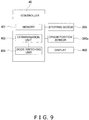
- FIG. 9 is a control block diagram of an actuator such as the stepping motor 395 shown in FIG. 7 .
- various sensors such as an origin position sensor 395a of the ball screw 393 driven by the stepping motor 395 are connected to the controller 40.
- the controller 40 reads the width dimension of the cardboard boxes B from cardboard box size input data when production starts or when products are switched and causes the stepping motor 395 to rotate to thereby automatically adjust the distance between the first guide plate 391 and the second guide plate 392.
- a mode switching unit 403 displays that the origin position sensor 395a is malfunctioning on the display 400 serving as a display unit, and preferably displays an indication that "The auto mode for adjusting the distance between the first guide plate 391 and the second guide plate 392 is inexecutable” and performs a display that asks "Would you like to manually adjust the distance between the first guide plate 391 and the second guide plate 392?"
- the determination unit 402 determines that the origin position sensor 395a is malfunctioning in a case where the position signal that should be detected is not being output from the origin position sensor 395a even though sufficient pulses are being input to the stepping motor 395.
- the operator selects the manual mode, in which the operator manually performs the adjustment of the distance between the first guide plate 391 and the second guide plate 392, presses the confirmation button displayed on the screen of the display 400, and confirms the switch to the manual mode.
- the function of the side surface pushing mechanism 355 is preventing uplift of the front or back of the cardboard box B, that function can also be realized by another configuration.
- the side surface of the cardboard box B can also be pushed by a rotatable roller instead of the friction surface 356a.
- the roller rotates as a result of rubbing against the side surface of the cardboard box B, so the side surface of the cardboard box B being conveyed can be inhibited from being scratched.
- the friction surface 356a moves together with the cardboard box B while holding down the side surface of the cardboard box B, so the friction surface 356a is inhibited from rubbing against the side surface of the cardboard box B and the side surface of the cardboard box B being conveyed can be inhibited from being scratched.
- the longitudinal directions of the folding bars 370a of the left/right flap folding members 370 are inclined with respect to the conveyance direction in such a way that the folding bars 370a come into contact with the front-side front edges of the left flap Zfal and the right flap Zfar in the conveyance direction, so the folding bars 370a can gradually fold the left flap Zfal and the right flap Zfar from the front-side front edges of the left flap Zfal and the right flap Zfar in the conveyance direction to the rear sides, and the left flap Zfal and the right flap Zfar are reliably folded along their fold lines.
- the folding operation becomes an operation where the folding bars 370a fold the left flap Zfal and the right flap Zfar from the upper portions of the left flap Zfal and the right flap Zfar to the bases, so the flaps can be folded neatly as if they were folded by hand.
- the folding bars 370a are inclined with respect to the conveyance direction also when they are descending, so a folding operation where the folding bars 370a fold the left flap Zfal and the right flap Zfar from the upper portions to the bases from the front of the left flap Zfal and the right flap Zfar to the rear becomes possible, and the flaps can be folded neatly as if they were folded by hand.
- the angle of inclination of the longitudinal directions of the folding bars 370a with respect to the conveyance direction of the cardboard boxes B is in the range of 3° to 60°.
- the folding bars 370a are inclined with respect to a horizontal plane when they come into contact with the left flap Zfal and the right flap Zfar.
- the folding bars 370a are provided in correspondence to each of the left flap Zfal and the right flap Zfar.
Landscapes
- Engineering & Computer Science (AREA)
- Mechanical Engineering (AREA)
- Closing Of Containers (AREA)
- Package Closures (AREA)
Claims (8)
- Kartonverschließvorrichtung (33), die eine Kartonschachtel (B) transportiert und gleichzeitig eine an Öffnungsrändern der Kartonschachtel (B) bereitgestellte Laschengruppe verschließt, wobei die Kartonverschließvorrichtung (33) umfasst:ein Faltelement (370), das eine Lasche (Zfal, Zfar) der Laschengruppe berührt, die sich entlang einer Förderrichtung der Kartonschachtel (B) erstreckt, und die Lasche (Zfal, Zfar) faltet;dadurch gekennzeichnet, dass die Kartonverschließvorrichtung (33) ferner umfasst:eine Antriebseinheit (375), die das Faltelement (370) bewegt; undeine Steuereinheit (40), die die Antriebseinheit (375) steuert,wobei im Vorgang des Faltens der Lasche (Zfal, Zfar) eine longitudinale Richtung des Faltelements (370) in Bezug auf die Förderrichtung geneigt ist, so dass das Faltelement (370) eine Vorderkante der Lasche (Zfal, Zfar) in der Förderrichtung vor anderen Abschnitten der Lasche (Zfal, Zfar) kontaktiert.
- Kartonverschließvorrichtung (33) gemäß Anspruch 1, wobei das Faltelement (370) sich nach Kontaktieren der Vorderkante der Lasche (Zfal, Zfar) allmählich absenkt.
- Kartonverschließvorrichtung (33) gemäß Anspruch 2, wobei das Faltelement (370) sich schräg nach unten absenkt.
- Kartonverschließvorrichtung gemäß Anspruch 2, wobei das Faltelement (370) sich absenkt während es sich dreht.
- Kartonverschließvorrichtung gemäß einem der Ansprüche 2 bis 4, wobei das Faltelement (370) beim Absenken in Bezug auf die Förderrichtung geneigt ist.
- Kartonverschließvorrichtung gemäß einem der Ansprüche 1 bis 5, wobei ein Neigungswinkel der longitudinalen Richtung des Faltelements (370) in Bezug auf die Förderrichtung in einem Bereich von 3° bis 60° liegt.
- Kartonverschließvorrichtung (33) gemäß einem der Ansprüche 1 bis 6, wobei das Faltelement (370) in Bezug auf eine horizontale Ebene geneigt ist, wenn das Faltelement (370) die Lasche (Zfal, Zfar) kontaktiert.
- Kartonverschließvorrichtung (33) gemäß einem der Ansprüche 1 bis 6, wobei das Faltelement (370) eine Vielzahl von Faltelementen (370a, 370b) beinhaltet, die für jede der Laschen (Zfal, Zfar) bereitgestellt sind, die sich entlang der Förderrichtung erstrecken.
Applications Claiming Priority (1)
| Application Number | Priority Date | Filing Date | Title |
|---|---|---|---|
| JP2018033026A JP7058442B2 (ja) | 2018-02-27 | 2018-02-27 | 封函装置 |
Publications (2)
| Publication Number | Publication Date |
|---|---|
| EP3530574A1 EP3530574A1 (de) | 2019-08-28 |
| EP3530574B1 true EP3530574B1 (de) | 2021-11-17 |
Family
ID=65598456
Family Applications (1)
| Application Number | Title | Priority Date | Filing Date |
|---|---|---|---|
| EP19159256.7A Active EP3530574B1 (de) | 2018-02-27 | 2019-02-26 | Kartondichtungsvorrichtung |
Country Status (5)
| Country | Link |
|---|---|
| US (1) | US10960997B2 (de) |
| EP (1) | EP3530574B1 (de) |
| JP (1) | JP7058442B2 (de) |
| CN (1) | CN110194285B (de) |
| ES (1) | ES2900510T3 (de) |
Families Citing this family (9)
| Publication number | Priority date | Publication date | Assignee | Title |
|---|---|---|---|---|
| CA3021452A1 (en) * | 2018-10-17 | 2020-04-17 | Thatbox Design, Llc | Improved manufacturing methods and apparatus for containers and packaging |
| US11298908B2 (en) * | 2019-02-13 | 2022-04-12 | Ishida Co., Ltd. | Lid forming device |
| US11464617B2 (en) * | 2019-04-19 | 2022-10-11 | Selenium Medical | Package, preferably medical, and corresponding set of packages |
| MY207948A (en) * | 2021-06-10 | 2025-03-31 | Afa Tech Sdn Bhd | An automated method and system for packaging flexible articles |
| US12338019B2 (en) * | 2021-08-27 | 2025-06-24 | Sky-Tag Robotics Sdn. Bhd. | Packing apparatus for loading compressible articles |
| US12151449B2 (en) | 2022-03-08 | 2024-11-26 | Signode Industrial Group Llc | Case-handling system with independently movable flap-suppressing devices |
| JP2023136997A (ja) | 2022-03-17 | 2023-09-29 | 株式会社イシダ | 箱詰装置 |
| CN117088143B (zh) * | 2022-05-12 | 2026-04-10 | 合肥博创智能包装设备有限公司 | 一种双列二次装袋机 |
| US12606337B2 (en) * | 2022-12-01 | 2026-04-21 | Sky-Tag Robotics Sdn. Bhd. | Packing apparatus and its method for loading articles into packaging |
Family Cites Families (22)
| Publication number | Priority date | Publication date | Assignee | Title |
|---|---|---|---|---|
| US3045402A (en) * | 1960-11-14 | 1962-07-24 | Gen Corrugated Machinery Compa | Machine for automatically measuring and taping cartons |
| US4262469A (en) * | 1979-06-06 | 1981-04-21 | Hans Ooms | Apparatus for closing boxes |
| US4551964A (en) * | 1979-09-12 | 1985-11-12 | Standard-Knapp, Inc. | Packing case tab slitter |
| ES2014017B3 (es) | 1986-01-20 | 1990-06-16 | Augusto Marchetti | Cerradora autoajustable de cajas de formato variable. |
| US4955177A (en) * | 1989-10-27 | 1990-09-11 | The Loveshaw Corporation | Carton flap folding apparatus |
| IT1252001B (it) * | 1991-11-11 | 1995-05-27 | Augusto Marchetti | Dispositivo per la chiusura delle falde laterali di scatole a falde ribaltabili |
| JP2669999B2 (ja) * | 1992-12-01 | 1997-10-29 | 日本フルート株式会社 | 封函方法およびその装置 |
| US5511362A (en) * | 1993-11-24 | 1996-04-30 | Nippon Flute Co., Ltd. | Box sealing method and apparatus |
| JP3032137U (ja) * | 1996-06-07 | 1996-12-17 | ナイガイ株式会社 | ダンボール箱シールテープ貼り機のフラップ自動折込み装置 |
| US6070396A (en) | 1996-11-27 | 2000-06-06 | Specialty Machinery, Inc. | Carton folding apparatus |
| JP2003095223A (ja) * | 2001-09-25 | 2003-04-03 | Sekisui Chem Co Ltd | 封緘機のフラップ折り込み装置 |
| ITMI20022429A1 (it) * | 2002-11-15 | 2004-05-16 | Antonio Marchetti | Dispositivo di raddrizzamento e chiusura della falda |
| US6910314B2 (en) * | 2002-12-30 | 2005-06-28 | Tuan Vinh Le | Random automatic case sealer |
| US7269933B2 (en) | 2003-05-16 | 2007-09-18 | Tuan Vinh Le | Random multi-stage automatic case sealer |
| JP5758644B2 (ja) * | 2011-02-14 | 2015-08-05 | 株式会社イシダ | ダンボール箱組立装置 |
| WO2016117183A1 (ja) * | 2015-01-23 | 2016-07-28 | 株式会社イシダ | 箱詰め装置 |
| CN105292547B (zh) * | 2015-11-05 | 2017-06-23 | 四川长虹电器股份有限公司 | 自动折叠纸箱上下盖装置 |
| CN205418173U (zh) * | 2016-03-10 | 2016-08-03 | 佛山市顺德区天键包装材料机械有限公司 | 自动折盖封箱机 |
| CN105836173B (zh) * | 2016-05-13 | 2018-01-30 | 江苏科技大学 | 一种可调节的全方位自动折页封箱机 |
| CN206087410U (zh) * | 2016-08-29 | 2017-04-12 | 贵州晟益科技有限公司 | 封箱机封顶机构 |
| CN206750208U (zh) * | 2017-04-28 | 2017-12-15 | 北京金维福仁清真食品有限公司 | 封箱机折盖机构及折盖封箱机 |
| US11298908B2 (en) * | 2019-02-13 | 2022-04-12 | Ishida Co., Ltd. | Lid forming device |
-
2018
- 2018-02-27 JP JP2018033026A patent/JP7058442B2/ja active Active
-
2019
- 2019-01-31 CN CN201910099841.5A patent/CN110194285B/zh active Active
- 2019-02-26 ES ES19159256T patent/ES2900510T3/es active Active
- 2019-02-26 US US16/285,211 patent/US10960997B2/en active Active
- 2019-02-26 EP EP19159256.7A patent/EP3530574B1/de active Active
Non-Patent Citations (1)
| Title |
|---|
| None * |
Also Published As
| Publication number | Publication date |
|---|---|
| JP7058442B2 (ja) | 2022-04-22 |
| US20190263547A1 (en) | 2019-08-29 |
| EP3530574A1 (de) | 2019-08-28 |
| CN110194285A (zh) | 2019-09-03 |
| JP2019147584A (ja) | 2019-09-05 |
| US10960997B2 (en) | 2021-03-30 |
| ES2900510T3 (es) | 2022-03-17 |
| CN110194285B (zh) | 2022-07-15 |
Similar Documents
| Publication | Publication Date | Title |
|---|---|---|
| EP3530574B1 (de) | Kartondichtungsvorrichtung | |
| EP3912919B1 (de) | Gehäuseherstellung, verpackung und dichtungsvorrichtung | |
| EP3530595B1 (de) | Packungssammelvorrichtung | |
| US11897224B2 (en) | Box forming apparatus and box forming and packing system | |
| JP2011031989A (ja) | 箱詰装置 | |
| US11975877B2 (en) | Case former with case-squaring assembly | |
| JP7199682B2 (ja) | 封函装置 | |
| JP2019147580A (ja) | 計量機、包装機、製品検査器あるいは箱詰め機である製品製造ラインの装置 | |
| EP3696097B1 (de) | Deckelformvorrichtung | |
| EP3597570A1 (de) | Artikelausrichtungsvorrichtung | |
| JP6996732B2 (ja) | 製函装置 | |
| JP6963205B2 (ja) | 物品整列装置 | |
| JP7056897B2 (ja) | 搬送装置 | |
| US20260116603A1 (en) | Folding apparatus and sealing apparatus | |
| EP4420990A1 (de) | Artikelfördervorrichtung | |
| CN113924254A (zh) | 用于填充阀袋的固定包装机组件的袋施加器组件、包括该袋施加器组件的固定包装机组件以及操作该袋施加器组件的方法 |
Legal Events
| Date | Code | Title | Description |
|---|---|---|---|
| PUAI | Public reference made under article 153(3) epc to a published international application that has entered the european phase |
Free format text: ORIGINAL CODE: 0009012 |
|
| STAA | Information on the status of an ep patent application or granted ep patent |
Free format text: STATUS: THE APPLICATION HAS BEEN PUBLISHED |
|
| AK | Designated contracting states |
Kind code of ref document: A1 Designated state(s): AL AT BE BG CH CY CZ DE DK EE ES FI FR GB GR HR HU IE IS IT LI LT LU LV MC MK MT NL NO PL PT RO RS SE SI SK SM TR |
|
| AX | Request for extension of the european patent |
Extension state: BA ME |
|
| STAA | Information on the status of an ep patent application or granted ep patent |
Free format text: STATUS: REQUEST FOR EXAMINATION WAS MADE |
|
| 17P | Request for examination filed |
Effective date: 20200226 |
|
| RBV | Designated contracting states (corrected) |
Designated state(s): AL AT BE BG CH CY CZ DE DK EE ES FI FR GB GR HR HU IE IS IT LI LT LU LV MC MK MT NL NO PL PT RO RS SE SI SK SM TR |
|
| STAA | Information on the status of an ep patent application or granted ep patent |
Free format text: STATUS: EXAMINATION IS IN PROGRESS |
|
| 17Q | First examination report despatched |
Effective date: 20200623 |
|
| GRAP | Despatch of communication of intention to grant a patent |
Free format text: ORIGINAL CODE: EPIDOSNIGR1 |
|
| STAA | Information on the status of an ep patent application or granted ep patent |
Free format text: STATUS: GRANT OF PATENT IS INTENDED |
|
| INTG | Intention to grant announced |
Effective date: 20210225 |
|
| GRAJ | Information related to disapproval of communication of intention to grant by the applicant or resumption of examination proceedings by the epo deleted |
Free format text: ORIGINAL CODE: EPIDOSDIGR1 |
|
| STAA | Information on the status of an ep patent application or granted ep patent |
Free format text: STATUS: EXAMINATION IS IN PROGRESS |
|
| GRAP | Despatch of communication of intention to grant a patent |
Free format text: ORIGINAL CODE: EPIDOSNIGR1 |
|
| STAA | Information on the status of an ep patent application or granted ep patent |
Free format text: STATUS: GRANT OF PATENT IS INTENDED |
|
| INTC | Intention to grant announced (deleted) | ||
| INTG | Intention to grant announced |
Effective date: 20210809 |
|
| GRAS | Grant fee paid |
Free format text: ORIGINAL CODE: EPIDOSNIGR3 |
|
| GRAA | (expected) grant |
Free format text: ORIGINAL CODE: 0009210 |
|
| STAA | Information on the status of an ep patent application or granted ep patent |
Free format text: STATUS: THE PATENT HAS BEEN GRANTED |
|
| AK | Designated contracting states |
Kind code of ref document: B1 Designated state(s): AL AT BE BG CH CY CZ DE DK EE ES FI FR GB GR HR HU IE IS IT LI LT LU LV MC MK MT NL NO PL PT RO RS SE SI SK SM TR |
|
| REG | Reference to a national code |
Ref country code: GB Ref legal event code: FG4D |
|
| REG | Reference to a national code |
Ref country code: IE Ref legal event code: FG4D |
|
| REG | Reference to a national code |
Ref country code: DE Ref legal event code: R096 Ref document number: 602019009251 Country of ref document: DE |
|
| REG | Reference to a national code |
Ref country code: AT Ref legal event code: REF Ref document number: 1447870 Country of ref document: AT Kind code of ref document: T Effective date: 20211215 |
|
| REG | Reference to a national code |
Ref country code: NO Ref legal event code: T2 Effective date: 20211117 |
|
| REG | Reference to a national code |
Ref country code: NL Ref legal event code: FP |
|
| REG | Reference to a national code |
Ref country code: LT Ref legal event code: MG9D |
|
| REG | Reference to a national code |
Ref country code: ES Ref legal event code: FG2A Ref document number: 2900510 Country of ref document: ES Kind code of ref document: T3 Effective date: 20220317 |
|
| REG | Reference to a national code |
Ref country code: AT Ref legal event code: MK05 Ref document number: 1447870 Country of ref document: AT Kind code of ref document: T Effective date: 20211117 |
|
| PG25 | Lapsed in a contracting state [announced via postgrant information from national office to epo] |
Ref country code: RS Free format text: LAPSE BECAUSE OF FAILURE TO SUBMIT A TRANSLATION OF THE DESCRIPTION OR TO PAY THE FEE WITHIN THE PRESCRIBED TIME-LIMIT Effective date: 20211117 Ref country code: LT Free format text: LAPSE BECAUSE OF FAILURE TO SUBMIT A TRANSLATION OF THE DESCRIPTION OR TO PAY THE FEE WITHIN THE PRESCRIBED TIME-LIMIT Effective date: 20211117 Ref country code: FI Free format text: LAPSE BECAUSE OF FAILURE TO SUBMIT A TRANSLATION OF THE DESCRIPTION OR TO PAY THE FEE WITHIN THE PRESCRIBED TIME-LIMIT Effective date: 20211117 Ref country code: BG Free format text: LAPSE BECAUSE OF FAILURE TO SUBMIT A TRANSLATION OF THE DESCRIPTION OR TO PAY THE FEE WITHIN THE PRESCRIBED TIME-LIMIT Effective date: 20220217 Ref country code: AT Free format text: LAPSE BECAUSE OF FAILURE TO SUBMIT A TRANSLATION OF THE DESCRIPTION OR TO PAY THE FEE WITHIN THE PRESCRIBED TIME-LIMIT Effective date: 20211117 |
|
| PG25 | Lapsed in a contracting state [announced via postgrant information from national office to epo] |
Ref country code: IS Free format text: LAPSE BECAUSE OF FAILURE TO SUBMIT A TRANSLATION OF THE DESCRIPTION OR TO PAY THE FEE WITHIN THE PRESCRIBED TIME-LIMIT Effective date: 20220317 Ref country code: SE Free format text: LAPSE BECAUSE OF FAILURE TO SUBMIT A TRANSLATION OF THE DESCRIPTION OR TO PAY THE FEE WITHIN THE PRESCRIBED TIME-LIMIT Effective date: 20211117 Ref country code: PT Free format text: LAPSE BECAUSE OF FAILURE TO SUBMIT A TRANSLATION OF THE DESCRIPTION OR TO PAY THE FEE WITHIN THE PRESCRIBED TIME-LIMIT Effective date: 20220317 Ref country code: PL Free format text: LAPSE BECAUSE OF FAILURE TO SUBMIT A TRANSLATION OF THE DESCRIPTION OR TO PAY THE FEE WITHIN THE PRESCRIBED TIME-LIMIT Effective date: 20211117 Ref country code: LV Free format text: LAPSE BECAUSE OF FAILURE TO SUBMIT A TRANSLATION OF THE DESCRIPTION OR TO PAY THE FEE WITHIN THE PRESCRIBED TIME-LIMIT Effective date: 20211117 Ref country code: HR Free format text: LAPSE BECAUSE OF FAILURE TO SUBMIT A TRANSLATION OF THE DESCRIPTION OR TO PAY THE FEE WITHIN THE PRESCRIBED TIME-LIMIT Effective date: 20211117 Ref country code: GR Free format text: LAPSE BECAUSE OF FAILURE TO SUBMIT A TRANSLATION OF THE DESCRIPTION OR TO PAY THE FEE WITHIN THE PRESCRIBED TIME-LIMIT Effective date: 20220218 |
|
| PG25 | Lapsed in a contracting state [announced via postgrant information from national office to epo] |
Ref country code: SM Free format text: LAPSE BECAUSE OF FAILURE TO SUBMIT A TRANSLATION OF THE DESCRIPTION OR TO PAY THE FEE WITHIN THE PRESCRIBED TIME-LIMIT Effective date: 20211117 Ref country code: SK Free format text: LAPSE BECAUSE OF FAILURE TO SUBMIT A TRANSLATION OF THE DESCRIPTION OR TO PAY THE FEE WITHIN THE PRESCRIBED TIME-LIMIT Effective date: 20211117 Ref country code: RO Free format text: LAPSE BECAUSE OF FAILURE TO SUBMIT A TRANSLATION OF THE DESCRIPTION OR TO PAY THE FEE WITHIN THE PRESCRIBED TIME-LIMIT Effective date: 20211117 Ref country code: EE Free format text: LAPSE BECAUSE OF FAILURE TO SUBMIT A TRANSLATION OF THE DESCRIPTION OR TO PAY THE FEE WITHIN THE PRESCRIBED TIME-LIMIT Effective date: 20211117 Ref country code: DK Free format text: LAPSE BECAUSE OF FAILURE TO SUBMIT A TRANSLATION OF THE DESCRIPTION OR TO PAY THE FEE WITHIN THE PRESCRIBED TIME-LIMIT Effective date: 20211117 Ref country code: CZ Free format text: LAPSE BECAUSE OF FAILURE TO SUBMIT A TRANSLATION OF THE DESCRIPTION OR TO PAY THE FEE WITHIN THE PRESCRIBED TIME-LIMIT Effective date: 20211117 |
|
| REG | Reference to a national code |
Ref country code: DE Ref legal event code: R097 Ref document number: 602019009251 Country of ref document: DE |
|
| PLBE | No opposition filed within time limit |
Free format text: ORIGINAL CODE: 0009261 |
|
| STAA | Information on the status of an ep patent application or granted ep patent |
Free format text: STATUS: NO OPPOSITION FILED WITHIN TIME LIMIT |
|
| PG25 | Lapsed in a contracting state [announced via postgrant information from national office to epo] |
Ref country code: MC Free format text: LAPSE BECAUSE OF FAILURE TO SUBMIT A TRANSLATION OF THE DESCRIPTION OR TO PAY THE FEE WITHIN THE PRESCRIBED TIME-LIMIT Effective date: 20211117 |
|
| REG | Reference to a national code |
Ref country code: CH Ref legal event code: PL |
|
| REG | Reference to a national code |
Ref country code: BE Ref legal event code: MM Effective date: 20220228 |
|
| 26N | No opposition filed |
Effective date: 20220818 |
|
| PG25 | Lapsed in a contracting state [announced via postgrant information from national office to epo] |
Ref country code: LU Free format text: LAPSE BECAUSE OF NON-PAYMENT OF DUE FEES Effective date: 20220226 Ref country code: AL Free format text: LAPSE BECAUSE OF FAILURE TO SUBMIT A TRANSLATION OF THE DESCRIPTION OR TO PAY THE FEE WITHIN THE PRESCRIBED TIME-LIMIT Effective date: 20211117 |
|
| PG25 | Lapsed in a contracting state [announced via postgrant information from national office to epo] |
Ref country code: SI Free format text: LAPSE BECAUSE OF FAILURE TO SUBMIT A TRANSLATION OF THE DESCRIPTION OR TO PAY THE FEE WITHIN THE PRESCRIBED TIME-LIMIT Effective date: 20211117 |
|
| PG25 | Lapsed in a contracting state [announced via postgrant information from national office to epo] |
Ref country code: FR Free format text: LAPSE BECAUSE OF NON-PAYMENT OF DUE FEES Effective date: 20220228 |
|
| PG25 | Lapsed in a contracting state [announced via postgrant information from national office to epo] |
Ref country code: LI Free format text: LAPSE BECAUSE OF NON-PAYMENT OF DUE FEES Effective date: 20220228 Ref country code: IE Free format text: LAPSE BECAUSE OF NON-PAYMENT OF DUE FEES Effective date: 20220226 Ref country code: CH Free format text: LAPSE BECAUSE OF NON-PAYMENT OF DUE FEES Effective date: 20220228 |
|
| PG25 | Lapsed in a contracting state [announced via postgrant information from national office to epo] |
Ref country code: BE Free format text: LAPSE BECAUSE OF NON-PAYMENT OF DUE FEES Effective date: 20220228 |
|
| PG25 | Lapsed in a contracting state [announced via postgrant information from national office to epo] |
Ref country code: MK Free format text: LAPSE BECAUSE OF FAILURE TO SUBMIT A TRANSLATION OF THE DESCRIPTION OR TO PAY THE FEE WITHIN THE PRESCRIBED TIME-LIMIT Effective date: 20211117 Ref country code: CY Free format text: LAPSE BECAUSE OF FAILURE TO SUBMIT A TRANSLATION OF THE DESCRIPTION OR TO PAY THE FEE WITHIN THE PRESCRIBED TIME-LIMIT Effective date: 20211117 |
|
| PG25 | Lapsed in a contracting state [announced via postgrant information from national office to epo] |
Ref country code: HU Free format text: LAPSE BECAUSE OF FAILURE TO SUBMIT A TRANSLATION OF THE DESCRIPTION OR TO PAY THE FEE WITHIN THE PRESCRIBED TIME-LIMIT; INVALID AB INITIO Effective date: 20190226 |
|
| PG25 | Lapsed in a contracting state [announced via postgrant information from national office to epo] |
Ref country code: MT Free format text: LAPSE BECAUSE OF FAILURE TO SUBMIT A TRANSLATION OF THE DESCRIPTION OR TO PAY THE FEE WITHIN THE PRESCRIBED TIME-LIMIT Effective date: 20211117 |
|
| PG25 | Lapsed in a contracting state [announced via postgrant information from national office to epo] |
Ref country code: TR Free format text: LAPSE BECAUSE OF FAILURE TO SUBMIT A TRANSLATION OF THE DESCRIPTION OR TO PAY THE FEE WITHIN THE PRESCRIBED TIME-LIMIT Effective date: 20211117 |
|
| PGFP | Annual fee paid to national office [announced via postgrant information from national office to epo] |
Ref country code: NL Payment date: 20260218 Year of fee payment: 8 |
|
| PGFP | Annual fee paid to national office [announced via postgrant information from national office to epo] |
Ref country code: GB Payment date: 20260219 Year of fee payment: 8 |
|
| PGFP | Annual fee paid to national office [announced via postgrant information from national office to epo] |
Ref country code: ES Payment date: 20260319 Year of fee payment: 8 |
|
| PGFP | Annual fee paid to national office [announced via postgrant information from national office to epo] |
Ref country code: NO Payment date: 20260217 Year of fee payment: 8 Ref country code: DE Payment date: 20260217 Year of fee payment: 8 |
|
| PGFP | Annual fee paid to national office [announced via postgrant information from national office to epo] |
Ref country code: IT Payment date: 20260227 Year of fee payment: 8 |