EP3519345B1 - Vorrichtung zum beeinflussen des volumenstroms eines füllprodukts in einer abfüllanlage - Google Patents
Vorrichtung zum beeinflussen des volumenstroms eines füllprodukts in einer abfüllanlage Download PDFInfo
- Publication number
- EP3519345B1 EP3519345B1 EP17777260.5A EP17777260A EP3519345B1 EP 3519345 B1 EP3519345 B1 EP 3519345B1 EP 17777260 A EP17777260 A EP 17777260A EP 3519345 B1 EP3519345 B1 EP 3519345B1
- Authority
- EP
- European Patent Office
- Prior art keywords
- housing
- valve
- pneumatic air
- filling
- control electronics
- Prior art date
- Legal status (The legal status is an assumption and is not a legal conclusion. Google has not performed a legal analysis and makes no representation as to the accuracy of the status listed.)
- Active
Links
- 238000001816 cooling Methods 0.000 claims description 27
- 238000013461 design Methods 0.000 claims description 12
- 230000001105 regulatory effect Effects 0.000 claims description 8
- 230000001276 controlling effect Effects 0.000 claims description 3
- 230000004941 influx Effects 0.000 claims 3
- 239000002699 waste material Substances 0.000 claims 1
- 235000013361 beverage Nutrition 0.000 description 12
- 238000000034 method Methods 0.000 description 9
- 238000005429 filling process Methods 0.000 description 7
- 238000004140 cleaning Methods 0.000 description 5
- 230000000694 effects Effects 0.000 description 4
- 239000000463 material Substances 0.000 description 4
- 239000000523 sample Substances 0.000 description 4
- 230000001954 sterilising effect Effects 0.000 description 4
- 238000004659 sterilization and disinfection Methods 0.000 description 4
- 238000004891 communication Methods 0.000 description 3
- 238000010276 construction Methods 0.000 description 2
- 238000010521 absorption reaction Methods 0.000 description 1
- 239000011248 coating agent Substances 0.000 description 1
- 238000000576 coating method Methods 0.000 description 1
- 230000001419 dependent effect Effects 0.000 description 1
- 238000011161 development Methods 0.000 description 1
- 230000018109 developmental process Effects 0.000 description 1
- 238000011143 downstream manufacturing Methods 0.000 description 1
- 238000007373 indentation Methods 0.000 description 1
- 238000009413 insulation Methods 0.000 description 1
- 230000010354 integration Effects 0.000 description 1
- 239000003973 paint Substances 0.000 description 1
- 230000005855 radiation Effects 0.000 description 1
- 230000035945 sensitivity Effects 0.000 description 1
- 238000012546 transfer Methods 0.000 description 1
- 238000011144 upstream manufacturing Methods 0.000 description 1
- 238000005303 weighing Methods 0.000 description 1
Images


Classifications
-
- B—PERFORMING OPERATIONS; TRANSPORTING
- B67—OPENING, CLOSING OR CLEANING BOTTLES, JARS OR SIMILAR CONTAINERS; LIQUID HANDLING
- B67C—CLEANING, FILLING WITH LIQUIDS OR SEMILIQUIDS, OR EMPTYING, OF BOTTLES, JARS, CANS, CASKS, BARRELS, OR SIMILAR CONTAINERS, NOT OTHERWISE PROVIDED FOR; FUNNELS
- B67C3/00—Bottling liquids or semiliquids; Filling jars or cans with liquids or semiliquids using bottling or like apparatus; Filling casks or barrels with liquids or semiliquids
- B67C3/02—Bottling liquids or semiliquids; Filling jars or cans with liquids or semiliquids using bottling or like apparatus
- B67C3/22—Details
- B67C3/28—Flow-control devices, e.g. using valves
- B67C3/286—Flow-control devices, e.g. using valves related to flow rate control, i.e. controlling slow and fast filling phases
-
- B—PERFORMING OPERATIONS; TRANSPORTING
- B67—OPENING, CLOSING OR CLEANING BOTTLES, JARS OR SIMILAR CONTAINERS; LIQUID HANDLING
- B67C—CLEANING, FILLING WITH LIQUIDS OR SEMILIQUIDS, OR EMPTYING, OF BOTTLES, JARS, CANS, CASKS, BARRELS, OR SIMILAR CONTAINERS, NOT OTHERWISE PROVIDED FOR; FUNNELS
- B67C3/00—Bottling liquids or semiliquids; Filling jars or cans with liquids or semiliquids using bottling or like apparatus; Filling casks or barrels with liquids or semiliquids
- B67C3/02—Bottling liquids or semiliquids; Filling jars or cans with liquids or semiliquids using bottling or like apparatus
- B67C3/22—Details
- B67C3/26—Filling-heads; Means for engaging filling-heads with bottle necks
-
- B—PERFORMING OPERATIONS; TRANSPORTING
- B67—OPENING, CLOSING OR CLEANING BOTTLES, JARS OR SIMILAR CONTAINERS; LIQUID HANDLING
- B67C—CLEANING, FILLING WITH LIQUIDS OR SEMILIQUIDS, OR EMPTYING, OF BOTTLES, JARS, CANS, CASKS, BARRELS, OR SIMILAR CONTAINERS, NOT OTHERWISE PROVIDED FOR; FUNNELS
- B67C3/00—Bottling liquids or semiliquids; Filling jars or cans with liquids or semiliquids using bottling or like apparatus; Filling casks or barrels with liquids or semiliquids
- B67C3/007—Applications of control, warning or safety devices in filling machinery
-
- B—PERFORMING OPERATIONS; TRANSPORTING
- B67—OPENING, CLOSING OR CLEANING BOTTLES, JARS OR SIMILAR CONTAINERS; LIQUID HANDLING
- B67C—CLEANING, FILLING WITH LIQUIDS OR SEMILIQUIDS, OR EMPTYING, OF BOTTLES, JARS, CANS, CASKS, BARRELS, OR SIMILAR CONTAINERS, NOT OTHERWISE PROVIDED FOR; FUNNELS
- B67C3/00—Bottling liquids or semiliquids; Filling jars or cans with liquids or semiliquids using bottling or like apparatus; Filling casks or barrels with liquids or semiliquids
- B67C3/02—Bottling liquids or semiliquids; Filling jars or cans with liquids or semiliquids using bottling or like apparatus
- B67C3/22—Details
- B67C3/28—Flow-control devices, e.g. using valves
-
- F—MECHANICAL ENGINEERING; LIGHTING; HEATING; WEAPONS; BLASTING
- F16—ENGINEERING ELEMENTS AND UNITS; GENERAL MEASURES FOR PRODUCING AND MAINTAINING EFFECTIVE FUNCTIONING OF MACHINES OR INSTALLATIONS; THERMAL INSULATION IN GENERAL
- F16K—VALVES; TAPS; COCKS; ACTUATING-FLOATS; DEVICES FOR VENTING OR AERATING
- F16K37/00—Special means in or on valves or other cut-off apparatus for indicating or recording operation thereof, or for enabling an alarm to be given
- F16K37/0025—Electrical or magnetic means
- F16K37/005—Electrical or magnetic means for measuring fluid parameters
-
- F—MECHANICAL ENGINEERING; LIGHTING; HEATING; WEAPONS; BLASTING
- F16—ENGINEERING ELEMENTS AND UNITS; GENERAL MEASURES FOR PRODUCING AND MAINTAINING EFFECTIVE FUNCTIONING OF MACHINES OR INSTALLATIONS; THERMAL INSULATION IN GENERAL
- F16K—VALVES; TAPS; COCKS; ACTUATING-FLOATS; DEVICES FOR VENTING OR AERATING
- F16K41/00—Spindle sealings
- F16K41/10—Spindle sealings with diaphragm, e.g. shaped as bellows or tube
-
- F—MECHANICAL ENGINEERING; LIGHTING; HEATING; WEAPONS; BLASTING
- F16—ENGINEERING ELEMENTS AND UNITS; GENERAL MEASURES FOR PRODUCING AND MAINTAINING EFFECTIVE FUNCTIONING OF MACHINES OR INSTALLATIONS; THERMAL INSULATION IN GENERAL
- F16K—VALVES; TAPS; COCKS; ACTUATING-FLOATS; DEVICES FOR VENTING OR AERATING
- F16K49/00—Means in or on valves for heating or cooling
- F16K49/005—Circulation means for a separate heat transfer fluid
-
- H—ELECTRICITY
- H05—ELECTRIC TECHNIQUES NOT OTHERWISE PROVIDED FOR
- H05K—PRINTED CIRCUITS; CASINGS OR CONSTRUCTIONAL DETAILS OF ELECTRIC APPARATUS; MANUFACTURE OF ASSEMBLAGES OF ELECTRICAL COMPONENTS
- H05K7/00—Constructional details common to different types of electric apparatus
- H05K7/20—Modifications to facilitate cooling, ventilating, or heating
- H05K7/20009—Modifications to facilitate cooling, ventilating, or heating using a gaseous coolant in electronic enclosures
- H05K7/20136—Forced ventilation, e.g. by fans
-
- H—ELECTRICITY
- H05—ELECTRIC TECHNIQUES NOT OTHERWISE PROVIDED FOR
- H05K—PRINTED CIRCUITS; CASINGS OR CONSTRUCTIONAL DETAILS OF ELECTRIC APPARATUS; MANUFACTURE OF ASSEMBLAGES OF ELECTRICAL COMPONENTS
- H05K7/00—Constructional details common to different types of electric apparatus
- H05K7/20—Modifications to facilitate cooling, ventilating, or heating
- H05K7/2039—Modifications to facilitate cooling, ventilating, or heating characterised by the heat transfer by conduction from the heat generating element to a dissipating body
- H05K7/20409—Outer radiating structures on heat dissipating housings, e.g. fins integrated with the housing
-
- H—ELECTRICITY
- H05—ELECTRIC TECHNIQUES NOT OTHERWISE PROVIDED FOR
- H05K—PRINTED CIRCUITS; CASINGS OR CONSTRUCTIONAL DETAILS OF ELECTRIC APPARATUS; MANUFACTURE OF ASSEMBLAGES OF ELECTRICAL COMPONENTS
- H05K7/00—Constructional details common to different types of electric apparatus
- H05K7/20—Modifications to facilitate cooling, ventilating, or heating
Definitions
- the present invention relates to a device for influencing the volume flow of a filling product in a bottling plant for filling a container with a filling product, for example for influencing the volume flow of the beverage to be filled when filling a beverage container with the beverage in a beverage bottling plant.
- Throttle valves are known for this purpose, which are switched into the filling product path between the filling product reservoir and the filling product outlet and by means of which the volume flow can be influenced.
- a valve which can be designed as a proportional valve and with which the volume flow of the filling product can be influenced. It is possible not only to switch between two different volumetric flows, i.e. between a first volumetric flow, in which the valve is fully open and a second volumetric flow, in which the valve is fully closed, but the proportional valve also makes it possible to switch between different or arbitrary set many different flow rates depending on the position of the valve cone relative to its valve seat.
- an actuator is provided in said proportional valve, by means of which different positions of the valve cone relative to the valve seat can be approached and in this way different volume flows can be adjusted.
- control electronics are provided, by means of which the actuator is actuated and which ensures that the volume flow required by a central controller is also provided by the respective individual proportional valve.
- a beverage bottling plant usually has a large number of bottling stations and each of these bottling stations is preceded by such a proportional valve in order to be able to control the volume flow which ultimately flows into the container to be filled according to the specifications of a central bottling control.
- a compact design of the proportional valve is aimed at by arranging the actuator and the control electronics in a housing directly connected to the valve body. Accordingly, the proportional valve can be placed in the beverage bottling plant as a compact unit.
- the WO 01/62059 A1 describes a valve with actuator for use in a hot environment.
- the DE 198 50 188 A1 describes an adapter for mounting an actuator to a valve.
- the EP 3 006 392 A2 describes a device for filling a container with a filling product.
- a device for influencing the volume flow of a filling product in a filling plant for filling filling products comprising a valve body with a valve seat and a valve cone movable relative thereto, an actuator for positioning the valve cone with respect to the valve seat, control electronics for controlling the actuator, and a housing which is connected directly to the valve body and in which the actuator and the control electronics are arranged.
- a device for reducing heat input into the control electronics is provided.
- the device for reducing the heat input into the control electronics is provided, the device for influencing the volume flow of the filling product, which is already compact in design by accommodating the control electronics in the housing and which is based on the provision of a central electronics box for accommodating the can do without the entire control electronics, can also be used in hot filling processes, since the heat input into the control electronics is reduced and negative effects on the control electronics can be avoided in this way.
- the device for reducing the heat input into the control electronics primarily serves to reduce the heat input emanating from the heated valve body.
- a device for influencing the volume flow can be provided in a compact manner and at the same time insensitivity to heat can be achieved, so that the device for influencing the volume flow, for example a proportional valve, can be used particularly flexibly in filling systems for filling products.
- the device for reducing the heat input into the control electronics also makes it possible to clean or sterilize the device for influencing the volume flow using high-temperature sterilization processes and high-temperature cleaning processes. Accordingly, the device can be used with all common filling methods and with all common cleaning and sterilization methods and at the same time provides a particularly compact structure.
- the device for reducing the heat input comprises cooling ribs, which are formed on an end of the valve body facing the housing. Accordingly can a heat flow, which is introduced into the valve body by the filling product or a sterilization medium, can be reduced in the direction of the housing. A heat flow from the valve body into the housing can be correspondingly reduced in that part of the heat introduced into the valve body via the filling product or the sterilization medium is released back to the environment via the cooling fins, and the heat flow from the valve body to the housing is correspondingly reduced .
- the reduction takes place on the one hand by the fact that heat is released to the environment via the cooling fins, and on the other hand the provision of cooling fins also reduces the total volume of material that can contribute to heat transport from the valve body to the housing.
- the cooling ribs in the valve body can either be arranged in the valve body itself, which also carries the valve seat and in which the valve cone is accommodated, or can be provided in an extension of the valve body, which can also be provided as a separate element of the valve body that is firmly connected to the valve body can be provided.
- the cooling fins are preferably formed in a hygienic design. Accordingly, the cooling fins do not have any undercuts, folds or hard edges in which foreign material could collect.
- the cooling ribs are preferably shaped in such a way that foreign material can be easily rinsed out or removed with a cleaning medium during the cleaning of the filling device.
- the device for reducing the heat input includes a pneumatic air supply for introducing pneumatic air into the housing.
- the pneumatic air which is already provided as the working medium in a filling device, is particularly preferably used to transport away the heat located in the housing.
- the pneumatic air supply particularly preferably has an expansion valve, a throttle valve or an opening with a reduced cross section for supplying expanded pneumatic air into the housing.
- the dried and pressurized pneumatic air is preferably expanded when entering the housing via the expansion valve, the throttle valve or the opening with a reduced cross-section, so that it cools down due to the Joule-Thomson effect and accordingly provides an additional cooling capacity to reduce the heat input into the control electronics.
- the pneumatic air is also applied to the control electronics in a targeted manner immediately after it has expanded in the housing, so that the control electronics are cooled before the pneumatic air, which is then still cool, gets through paint the rest of the case.
- the housing and the pneumatic air supply are geometrically designed in such a way that the air flow within the housing ensures that the expanded and correspondingly cold and dry pneumatic air first acts on the control electronics or other temperature-sensitive components within the housing and then flows through the rest of the housing and via a air outlet leaves the housing again.
- the pneumatic air is preferably discharged from the housing to the outside via defined channels, with an outlet valve or non-return valve ensuring that when the pneumatic air supply is switched off, moisture and foreign bodies do not enter the housing in an uncontrolled manner.
- the supply of pneumatic air via the pneumatic air supply is particularly preferably regulated or controlled by means of a control valve using a temperature sensor provided in the housing.
- a constant supply of pneumatic air can also be carried out.
- the pneumatic air introduced into the housing is routed from the housing through the valve body, in particular through the actuator, through a bellows shielding the plunger of the valve cone from the filling product and then via a defined outlet into the environment. Accordingly, the pneumatic air does not come into contact with the filling product, but serves both to reduce the heat input in the housing and in particular on the control electronics and, due to the flow through the actuator, also leads to cooling of the actuator.
- a valve block is arranged on the housing and preferably the actuator of the valve, particularly preferably the actuator of a pilot valve, is accommodated in the housing.
- a valve block in particular a valve block with pilot valves for further control of upstream or downstream processes of the bottling plant with the device for influencing the volume flow can also be designed in a compact manner.
- the pilot valves or the drives of the pilot valves can also be accommodated by the housing, so that the drives of the pilot valves can also benefit from the device for reducing the heat input into the control electronics.
- the housing can have an open flange on one side, instead of a closing plate, on which the valve block can be mounted.
- a seal is preferably provided between the valve block and the housing.
- the valve block can also be welded to the housing for integration into the housing.
- pilot valves and at least their drives are preferably also accommodated in the housing in this embodiment in order to benefit from the device for reducing the heat input into the control electronics.
- valve block is designed in such a way that the pneumatic exhaust air from the valves, preferably the pilot valves, is routed into the housing.
- the pilot valves also vent into the housing, so that when a container is filled with a filling product and a corresponding complete switching of the valves and pilot valves is carried out through a complete switching cycle, a pneumatic air flow can be provided through the housing by the exhaust air of the pneumatic system, which serves to reduce the heat input into the control electronics.
- further interfaces are preferably also integrated into the housing in order to be able to connect, for example, flow meters, load cells or short-circuit probes to the control electronics in such a way that regulation of the Device for influencing the volume flow can be performed on the basis of the corresponding sensor signals.
- the position of the valve tappet can be regulated via a flow sensor in such a way that a specific, intended flow is achieved.
- the same can also be achieved via the signal from a load cell or the signal from a short-circuit probe, whereby the exact process of filling the filling product into the container to be filled can be tracked via the load cell, but only the achievement of a certain filling level via a short-circuit probe can be used, for example, as a trigger for a reduction in the volume flow in the last filling section.
- the electronics which were previously arranged centrally, can essentially be relocated to the respective device for influencing the volume flow, so that the device can be constructed more compactly overall and the need for wiring can be reduced.
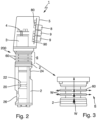
- figure 1 shows a device 1 for influencing the volume flow of a filling product in a bottling plant for bottling filling products according to the prior art, for example for bottling beverages in a beverage bottling plant.
- the device 1 comprises a valve body 2 which defines a valve seat 20 which is in communication with an inlet 24 and an outlet 26 for the filling product.
- a valve cone 22 is accommodated in the valve body 2, which can be lowered into the valve seat 22 with a seal or partial seal and lifted out of the valve seat 20 again, so that the volume flow of the filling product, which flows via the inlet 24 into the valve body 2 and into the valve seat 22 forming cavity occurs through the annular gap between Valve seat 20 and valve cone 22 flows and then leaves the valve body 2 again via the outlet 26 .
- the flow path of the filling product through the device 1 is in FIG figure 1 represented schematically by the arrow F.
- the volume flow of the filling product flowing through the device 1 can be controlled or regulated. If, for example, the valve cone 22 is completely lifted out of the valve seat 20, the filling product flows unhindered out of the outlet 26 and the volumetric flow is not throttled—apart from the flow resistance already predetermined by the device 1. If a throttling of the volume flow of the filling product is desired, the valve cone 22 can be lowered in the direction of the valve seat 20 by a corresponding amount in order to reduce the annular gap between the valve cone 22 and the valve seat 20 and thus achieve the desired reduced volume flow.
- an actuator 3 is provided, which can be provided, for example, in the form of an electric motor or another electromechanical drive, which is mechanically coupled to the valve cone 22, for example via a tappet, in such a way that when the actuator 3 is actuated, a corresponding positioning of the valve cone 22 relative to the valve seat 20 can be achieved.
- control electronics 4 are provided, which enable the actuator 3 to be controlled on the basis of external control signals, on the basis of logic provided by the control electronics 4 itself, or on the basis of a combination of both options.
- the control electronics 4 can process different external control signals, evaluate and process sensor signals and/or process feedback from the actuator 3 in order to ultimately position the valve cone 22 relative to the valve seat 20 and thus a volume flow according to the specifications of the filling process or the specifications to achieve a central filling control.
- the actuator 3 and the control electronics 4 are accommodated in a housing 5 which is connected directly to the valve body 2 and, according to the known embodiment, forms a seal with the valve body 2 .
- a housing 5 which is connected directly to the valve body 2 and, according to the known embodiment, forms a seal with the valve body 2 .
- valve body 2 has a device 6 for reducing the heat input into the control electronics 4 in the form of cooling fins 60 .
- the device 6 for reducing the heat input into the control electronics 4 serves in particular to reduce the heat input, which emanates from the valve body 2, into the control electronics 4.
- the provision of the cooling fins 60 reduces the flow of heat which flows from the valve body 2 to the housing 5 when a hot filling product flows through the valve body 2 . Correspondingly, the heat input into the control electronics 4 is reduced.
- the device for reducing the heat input 6 in the form of the cooling ribs 60 is preferably designed in such a way that the largest possible proportion of the thermal energy flowing from the valve body 2 in the direction of the housing 5 is already radiated by means of the cooling ribs 60 and accordingly does not flow into the housing 5 .
- the flow of heat and the radiation of thermal energy due to the cooling fins 60 is shown in the detailed illustration of the cooling fins 60 in figure 3 represented schematically by the arrows W.
- the cooling fins 60 are on accordingly that end 200 of the valve body 2 is provided, to which the housing 5 is connected.
- the cooling ribs 60 thus provide a kind of partial insulation between the valve body 2 and the housing 5 .
- the cooling fins 60 are, as for example from the detailed representation of the figure 3 to recognize, preferably designed so that undercuts and edges in which foreign material could accumulate can be avoided. In this way, a hygienic design can be provided, which is of particular importance in the field of bottling food and beverages.
- the surfaces of the cooling ribs 60 are correspondingly smooth and the shape is rounded in such a way that foreign matter cannot become lodged and can be rinsed out reliably and easily during a cleaning cycle.
- further electronic modules 90 for evaluating sensor signals supplied via an additional sensor interface 9 can also be provided in the housing 5 .
- communication modules 80 can also be provided for connecting the device 1 to a higher-level controller, for example to the system controller.
- the sensor interface 9 it is preferred for the sensor interface 9 to enable a connection to a flow meter, by means of which the position of the valve cone 22 relative to the valve seat 20 can then be regulated according to corresponding specifications for the volume flow.
- a connection to a weighing cell can also be provided, by means of which the volume flow flowing into the container to be filled can be determined and the position of the valve cone 22 relative to the valve seat 20 can be regulated accordingly.
- the sensor interface 9 can also be provided for connecting a short-circuit probe, which dips into the container to be filled in order to signal a certain filling threshold, from which a change in the volume flow flowing into the container should be made, for example towards the end of the filling process.
- a device for reducing the heat input 6 in the form of a pneumatic air supply 62 is provided on the housing 5 .
- Pneumatic air which is provided anyway as a working medium in a filling system for filling the filling product, can be introduced into the housing 5 via the pneumatic air supply 62 and heat can be transported away in this way, so that a reduction in the heat input into the control electronics 4 is also achieved here becomes.
- an air outlet 626 is preferably provided, which is arranged in such a way that the pneumatic air supplied via the pneumatic air supply 62 flows through the housing 5 evenly and preferably also as a function of the temperature sensitivity of the respective components within the housing 5 crossed out.
- the air outlet 626 is preferably provided with a non-return valve, so that when the pneumatic air supply 62 is switched off, the ingress of foreign bodies and moisture into the housing 5 is prevented.
- the air flow of the pneumatic air through the housing 5 and past the switching electronics 4 is indicated schematically by the arrow L in the figure.
- the pneumatic air supply 62 into the housing 5 can preferably be carried out via an expansion valve, a throttle valve or an opening with a reduced cross section 620 in such a way that the supplied and pressurized, dried pneumatic air from the pneumatic system of the bottling plant expands and the pneumatic air enters the housing 5 is cooled down accordingly.
- cooling is also explicitly provided at this point by the Joule-Thomson effect, which also serves to reduce the heat input into the control electronics 4 .
- the pneumatic air supply 62 and in particular the orientation of the opening with a reduced cross section 620 is selected in such a way that the expanded, dried and cooled by the expansion pneumatic air first hits the particularly temperature-sensitive components inside the housing 6, in particular the control electronics 4, so that Way a cooling and thus a reduction of the heat input into the control electronics 4 is achieved.
- the supply of pneumatic air via the pneumatic air supply 62 can be controlled or regulated via a control valve 622 .
- a control valve 622 In this case, either a constant quantity of pneumatic air can be provided and passed through the housing 5 in order to achieve the reduction accordingly to achieve the heat input into the control electronics 4.
- it can also be carried out by means of a temperature sensor 624 provided in the housing 5 via control or regulation of the supply of the quantity of pneumatic air.
- the supply of pneumatic air can be increased by means of the control valve 622 and if the temperature falls below certain threshold values, the supply of pneumatic air can be reduced.
- the temperature sensor 624 can preferably also be provided directly on the printed circuit board of the control electronics 4 in order to monitor the temperature of the control electronics 4 directly.
- the consumption of pneumatic air can be optimized and at the same time it can be ensured that the electronic control system 4 is always operated in an optimized temperature range and thus the heat input into the electronic control system 4 is reduced.
- FIG 5 a schematic sectional view of a device 1 is shown in a further embodiment, in which the housing 5 is provided with a flange 52 on its upper side 50 .
- a valve block 7 is placed on the flange 52, preferably using a seal 54, which then closes the housing 5 at the top.
- the valve block 7 can also be welded directly to the housing 5 instead of being screwed together using the flange 52 .
- the valve block 7 In addition to a pneumatic air supply 70 and a pneumatic air discharge 72, the valve block 7 also includes a plurality of pilot valves 74.
- the pilot valves 74 are provided for switching different pneumatic processes within the filling system.
- the pilot valves 74 vent into the housing 5 .
- the pneumatic air discharge 72 can also be routed into the housing 5 . In this way, a reduction in the input of thermal energy into the switching electronics 4 can be achieved in that the pneumatic air already used in the valve block 7 is expanded into the housing 5 and in this way for the components provided in the housing 5 and in particular for the switching electronics 4 leads to a reduction in the heat input and ensures that the heat energy is transported away. Because the exhaust air from the valve block 7 that is present anyway is used, the use of additional pneumatic air can be saved.
- the pneumatic air preferably flows through the housing 5 and through the actuator 3, i.e. between the rotor and stator of the actuator 3, and then through a bellows 28, which is provided to seal the actuator 3 from the filling product, and then via a The screw fixing the valve cone 22 and designed accordingly as an air outlet 626 to be derived from the device 1 .
- the air flow is indicated by the arrow L.
- the pneumatic air flows not only through the interior of the housing 5, but also through the actuator 3 and parts of the valve body 2, in order in this way to enable thermal energy to be transported away.
- the inner sides of the housing 5 can furthermore also be provided with a black coating in order to enable increased heat absorption and accordingly to enable the heat energy introduced into the housing to be transported away to the outside.
- improved heat transfer of the thermal energy generated by the actuator 3 to the wall of the housing 5 can also ensure that the thermal energy introduced into the interior of the housing 5 via the actuator 3 is transported away via the housing wall to the outside and radiated.
- Improved thermal conduction can be achieved, for example, via direct metallic connections, thermally conductive pads, thermally conductive paste or a corresponding structural indentation of the housing wall toward the actuator 3 .
- the thermal energy introduced by the actuator 3 can also be reduced in that the actuator 3 is controlled on the basis of the torque actually required because the bellows 28 are usually less stiff at higher temperatures and a correspondingly lower torque is required, so that the actuator 3 can then be operated with less energy and correspondingly less heat enters the interior of the housing 5 .
Description
- Die vorliegende Erfindung betrifft eine Vorrichtung zum Beeinflussen des Volumenstroms eines Füllprodukts in einer Abfüllanlage zum Befüllen eines Behälters mit einem Füllprodukt, beispielsweise zum Beeinflussen des Volumenstroms des abzufüllenden Getränks beim Befüllen eines Getränkebehälters mit dem Getränk in einer Getränkeabfüllanlage.
- In Getränkeabfüllanlagen ist es bekannt, den Volumenstrom des aus einem Füllproduktreservoir zu dem eigentlichen Füllventil strömenden Füllprodukts zu beeinflussen und insbesondere zu steuern oder zu regeln. Hierzu sind Drosselventile bekannt, welche in den Füllproduktweg zwischen das Füllproduktreservoir und den Füllproduktauslass geschaltet werden und mittels welchen der Volumenstrom beeinflusst werden kann.
- Beispielsweise ist aus der
WO 2014/009362 A2 ein Ventil bekannt, welches als Proportionalventil ausgebildet sein kann und mit welchem der Volumenstrom des Füllprodukts beeinflusst werden kann. Dabei ist es möglich, nicht nur zwischen zwei unterschiedlichen Volumenströmen zu schalten, also zwischen einem ersten Volumenstrom, bei welchem das Ventil vollständig geöffnet ist und einem zweiten Volumenstrom, bei welchem das Ventil vollständig geschlossen ist, sondern das Proportionalventil ermöglicht es, unterschiedliche bzw. beliebig viele unterschiedliche Volumenströme je nach Stellung des Ventilkegels relativ zu dessen Ventilsitz einzustellen. Hierzu ist in dem genannten Proportionalventil ein Aktuator vorgesehen, mittels welchem unterschiedliche Positionen des Ventilkegels gegenüber dem Ventilsitz angefahren werden können und auf diese Weise unterschiedliche Volumenströme eingestellt werden können. - Um mittels des Proportionalventils einen reproduzierbaren Volumenstrom in der Abfüllvorrichtung bereitzustellen, ist eine Ansteuerelektronik vorgesehen, mittels welcher der Aktuator betätigt werden kann und welche dafür sorgt, dass der von einer zentralen Steuerung geforderte Volumenstrom durch das jeweilige individuelle Proportionalventil auch bereitgestellt wird.
- In einer Getränkeabfüllanlage ist üblicherweise eine Vielzahl an Abfüllstellen vorgesehen und jeder dieser Abfüllstellen ist ein solches Proportionalventil vorgeschaltet, um den Volumenstrom, welcher schlussendlich in den zu befüllenden Behälter einströmt, den jeweiligen Vorgaben einer zentralen Abfüllsteuerung entsprechend steuern zu können.
- Ein kompakter Aufbau des Proportionalventils wird darüber angestrebt, dass der Aktuator und die Steuerungselektronik in einem mit dem Ventilkörper direkt verbundenen Gehäuse angeordnet sind. Entsprechend kann das Proportionalventil in der Getränkeabfüllanlage als kompakte Einheit platziert werden.
- Aufgrund der Anordnung von Steuerelektronik und Aktuator in einem sich direkt an den Ventilkörper anschließenden Gehäuse ergibt sich jedoch, dass ein solches kompaktes Proportionalventil nur in Getränkeabfüllanlagen verwendet werden kann, welche für die Kaltabfüllung vorgesehen sind, da ein zu hoher Wärmeeintrag in die Steuerungselektronik die Funktionalität und Dauerhaltbarkeit der Steuerungselektronik negativ beeinflussen kann. Entsprechend ist es in bekannten Vorrichtungen notwendig gewesen, die Steuerelektronik bei Abfüllanlagen, welche für die Durchführung von Abfüllverfahren bei hohen Temperaturen vorgesehen sind, in einem separaten Elektronikkasten unterzubringen, um eine thermische Entkopplung von heißem Ventilkörper und Steuerelektronik bereitzustellen. Entsprechend ließ sich auf diese Weise ein kompakter Aufbau der Proportionalventile und damit der gesamten Getränkeabfüllanlage nicht erreichen.
- Die
WO 01/62059 A1 DE 198 50 188 A1 beschreibt einen Adapter zur Montage einer Betätigungseinrichtung an einem Ventil. DieEP 3 006 392 A2 beschreibt eine Vorrichtung zum Befüllen eines Behälters mit einem Füllprodukt. - Entsprechend ist es eine Aufgabe der vorliegenden Erfindung, eine kompakte Vorrichtung zum Beeinflussen des Volumenstroms eines Füllprodukts bereitzustellen, welche auch in Heißabfüllverfahren verwendet werden kann.
- Diese Aufgabe wird durch eine Vorrichtung zum Beeinflussen des Volumenstroms in einer Abfüllanlage mit den Merkmalen des Anspruchs 1 gelöst. Vorteilhafte Weiterbildungen ergeben sich aus den Unteransprüchen, der Beschreibung sowie den Figuren.
- Entsprechend wird eine Vorrichtung zum Beeinflussen des Volumenstroms eines Füllprodukts in einer Abfüllanlage zum Abfüllen von Füllprodukten vorgeschlagen, umfassend einen Ventilkörper mit einem Ventilsitz und einen relativ zu diesem bewegbaren Ventilkegel, einen Aktuator zum Positionieren des Ventilkegels bezüglich des Ventilsitzes, eine Steuerelektronik zum Ansteuern des Aktuators, sowie ein Gehäuse, welches direkt mit dem Ventilkörper verbunden ist und in welchem der Aktuator und die Steuerelektronik angeordnet sind. Erfindungsgemäß ist eine Einrichtung zum Reduzieren eines Wärmeeintrags in die Steuerelektronik vorgesehen.
- Dadurch, dass die Einrichtung zum Reduzieren des Wärmeeintrags in die Steuerelektronik vorgesehen ist, kann die Vorrichtung zum Beeinflussen des Volumenstroms des Füllprodukts, die durch die Aufnahme der Steuerelektronik in dem Gehäuse bereits kompakt ausgebildet ist und welche entsprechend auf die Bereitstellung eines zentralen Elektronikkastens zur Aufnahme der gesamten Steuerelektronik verzichten kann, auch in Heißabfüllverfahren verwendet werden, da der Wärmeeintrag in die Steuerelektronik reduziert wird und auf diese Weise negative Effekte auf die Steuerelektronik vermieden werden können.
- Die Einrichtung zum Reduzieren des Wärmeeintrags in die Steuerelektronik dient dabei vornehmlich dazu, den von dem erwärmten Ventilkörper ausgehenden Wärmeeintrag zu reduzieren.
- Mit anderen Worten kann auf diese Weise eine Vorrichtung zum Beeinflussen des Volumenstroms in kompakter Weise bereitgestellt werden und gleichzeitig eine Hitzeunempfindlichkeit erreicht werden, so dass die Vorrichtung zur Beeinflussung des Volumenstroms, beispielsweise ein Proportionalventil, besonders flexibel in Abfüllanlagen für Füllprodukte eingesetzt werden kann.
- Durch die Einrichtung zum Reduzieren des Wärmeeintrags in die Steuerelektronik ist es weiterhin möglich, die Vorrichtung zum Beeinflussen des Volumenstroms auch mit Hochtemperatursterilisierungsverfahren und Hochtemperaturreinigungsverfahren zu reinigen bzw. zu sterilisieren. Die Vorrichtung kann entsprechend mit sämtlichen üblichen Abfüllverfahren und mit sämtlichen üblichen Reinigungs- und Sterilisierungsverfahren verwendet werden und stellt gleichzeitig dennoch einen besonders kompakten Aufbau bereit.
- Vorteilhaft umfasst die Einrichtung zum Reduzieren des Wärmeeintrags Kühlrippen, welche an einem dem Gehäuse zugewendeten Ende des Ventilkörpers ausgebildet sind. Entsprechend kann ein Wärmefluss, der durch das Füllprodukt oder ein Sterilisationsmedium in den Ventilkörper eingetragen wird, in Richtung des Gehäuses reduziert werden. Ein Wärmefluss vom Ventilkörper in das Gehäuse kann entsprechend dadurch reduziert werden, dass ein Teil der über das Füllprodukt oder das Sterilisationsmedium in den Ventilkörper eingetragene Wärme über die Kühlrippen wieder an die Umgebung abgegeben wird, und entsprechend der Wärmefluss von dem Ventilkörper an das Gehäuse reduziert wird. Die Reduktion findet dabei zum einen dadurch statt, dass über die Kühlrippen Wärme an die Umgebung abgegeben wird, und zum anderen wird durch das Bereitstellen von Kühlrippen auch das Materialvolumen insgesamt reduziert, welches überhaupt zu einem Wärmetransport von dem Ventilkörper an das Gehäuse beitragen kann.
- Die Kühlrippen im Ventilkörper können dabei entweder in dem Ventilkörper selbst angeordnet sein, welcher auch den Ventilsitz trägt und in welchem der Ventilkegel aufgenommen ist, oder können in einer Verlängerung des Ventilkörpers, welcher auch als separates, aber fest mit dem Ventilkörper verbundenen Element des Ventilkörpers vorgesehen sein kann, vorgesehen sein.
- Die Kühlrippen sind bevorzugt in einem hygienischen Design ausgebildet. Entsprechend weisen die Kühlrippen keine Hinterschnitte, Falze oder harte Kanten auf, in welchen sich Fremdmaterial sammeln könnte. Bevorzugt ist eine Formung der Kühlrippen derart ausgebildet, dass Fremdmaterial während der Reinigung der Füllvorrichtung einfach mit einem Reinigungsmedium ausgespült bzw. entfernt werden kann.
- In einer vorteilhaften Ausbildung umfasst die Einrichtung zum Reduzieren des Wärmeeintrags eine Pneumatikluftzufuhr zum Einbringen von Pneumatikluft in das Gehäuse. Besonders bevorzugt wird hier die ohnehin in einer Abfüllvorrichtung als Arbeitsmedium vorgesehene Pneumatikluft dazu verwendet, die im Gehäuse befindliche Wärme abzutransportieren.
- Besonders bevorzugt weist die Pneumatikluftzufuhr ein Expansionsventil, ein Drosselventil oder eine Öffnung reduzierten Querschnitts zum Zuführen expandierter Pneumatikluft in das Gehäuse auf.
- Die getrocknete und unter Überdruck stehende Pneumatikluft wird auf diese Weise bevorzugt beim Eintreten in das Gehäuse über das Expansionsventil, das Drosselventil oder die Öffnung reduzierten Querschnitts expandiert, so dass sie aufgrund des Joule-Thomson-Effekts abkühlt und entsprechend eine zusätzliche Kühlleistung zum Reduzieren des Wärmeeintrags in die Steuerelektronik bereitstellt.
- In einer besonders bevorzugten Variante wird nicht nur das gesamte Gehäuseinnere von der Pneumatikluft durchströmt, sondern es findet ein gezieltes Beaufschlagen der Steuerelektronik durch die Pneumatikluft direkt nach deren Expansion im Gehäuse statt, so dass die Steuerelektronik gekühlt wird, bevor die dann immer noch kühle Pneumatikluft durch das restliche Gehäuse streicht.
- Entsprechend sind das Gehäuse sowie die Pneumatikluftzufuhr geometrisch so ausgelegt, dass die Luftführung innerhalb des Gehäuses dafür sorgt, dass die expandierte und entsprechend kalte und trockene Pneumatikluft zunächst die Steuerelektronik bzw. andere temperaturempfindliche Bestandteile innerhalb des Gehäuses beaufschlagt und dann das restliche Gehäuse durchströmt und über einen Luftauslass das Gehäuse wieder verlässt.
- Die Pneumatikluft wird dabei bevorzugt über definierte Kanäle aus dem Gehäuse nach außen abgeleitet, wobei über ein Auslassventil oder Rückschlagventil sichergestellt wird, dass beim Abschalten der Pneumatikluftzufuhr Feuchtigkeit und Fremdkörper nicht unkontrolliert in das Gehäuse eintreten.
- Besonders bevorzugt ist die über die Pneumatikluftzufuhr vorgenommen Zufuhr von Pneumatikluft mittels eines Steuerventils anhand eines im Gehäuse vorgesehenen Temperatursensors geregelt oder gesteuert. Alternativ kann auch eine konstante Pneumatikluftzufuhr vorgenommen werden.
- In einer besonders bevorzugten Variante wird die in das Gehäuse eingeleitete Pneumatikluft von dem Gehäuse durch den Ventilkörper, insbesondere durch den Aktuator, durch einen den Stößel des Ventilkegels gegenüber dem Füllprodukt abschirmenden Faltenbalg hindurch und dann über einen definierten Auslass in die Umgebung geleitet. Die Pneumatikluft kommt entsprechend nicht mit dem Füllprodukt in Berührung, dient jedoch sowohl zur Reduktion des Wärmeeintrags im Gehäuse und insbesondere an der Steuerelektronik und führt durch die Durchströmung des Aktuators auch zu einer Kühlung des Aktuators.
- In einer vorteilhaften Ausgestaltung ist an dem Gehäuse ein Ventilblock angeordnet und bevorzugt der Aktuator des Ventils, besonders bevorzugt der Aktuator eines Vorsteuerventils, in dem Gehäuse aufgenommen.
- Auf diese Weise kann auch ein Ventilblock, insbesondere ein Ventilblock mit Vorsteuerventilen zum weiteren Ansteuern vorgelagerter oder nachgelagerter Prozesse der Abfüllanlage mit der Vorrichtung zum Beeinflussen des Volumenstroms in kompakter Weise ausgebildet sein. Die Vorsteuerventile bzw. die Antriebe der Vorsteuerventile können dabei ebenfalls von dem Gehäuse aufgenommen sein, so dass auch die Antriebe der Vorsteuerventile durch die Einrichtung zum Reduzieren des Wärmeeintrags in die Steuerelektronik profitieren können.
- Um einen kompakten Aufbau zu erreichen, kann das Gehäuse an einer Seite anstatt einer verschließenden Platte einen offenen Flansch aufweisen, an welchem der Ventilblock montiert werden kann. Bevorzugt ist eine Abdichtung zwischen Ventilblock und Gehäuse vorgesehen. Der Ventilblock kann aber auch zur Integration in das Gehäuse mit dem Gehäuse verschweißt werden.
- Die Vorsteuerventile sowie zumindest deren Antriebe sind bevorzugt auch in dieser Ausführungsform in dem Gehäuse aufgenommen, um von der Einrichtung zum Reduzieren des Wärmeeintrags in die Steuerelektronik zu profitieren.
- Eine besonders vorteilhafte Ausbildung ergibt sich, wenn der Ventilblock so ausgebildet ist, dass die Pneumatikabluft der Ventile, bevorzugt der Vorsteuerventile, in das Gehäuse geleitet wird. Mit anderen Worten entlüften die Vorsteuerventile auch in das Gehäuse, so dass beim Durchlaufen eines vollständigen Schaltzyklus beim Befüllen eines Behälters mit einem Füllprodukt und einer entsprechenden vollständigen Schaltung der Ventile und Vorsteuerventile durch die Abluft der Pneumatik ein Pneumatikluftstrom durch das Gehäuse hindurch bereitgestellt werden kann, welcher zur Reduktion des Wärmeeintrags in die Steuerelektronik dient.
- Auf diese Weise ist es möglich, die sonst abgeführte, bereits verwendete Pneumatikluft noch zur Reduktion des Wärmeeintrags in die Steuerelektronik zu verwenden. Auf diese Weise kann auf eine separate Zufuhr von Pneumatikluft zur Reduktion des Wärmeeintrags in die Steuerelektronik verzichtet werden bzw. der Zufluss von Pneumatikluft zur Reduktion des Wärmeeintrags in die Steuerelektronik kann reduziert werden, so dass auf diese Weise insgesamt eine Reduktion des Verbrauchs an Pneumatikluft erreicht werden kann bei gleichzeitig sehr kompaktem Aufbau der Vorrichtung und Sicherstellen der Langlebigkeit bzw. Funktion der Schaltelektronik.
- Um weiterhin einen kompakten Aufbau bereitzustellen und die Notwendigkeit für einen ausgelagerten, zentralen Elektronikkasten der Abfüllanlage weiter zu reduzieren, werden bevorzugt auch weitere Schnittstellen in das Gehäuse integriert, um beispielsweise Durchflussmesser, Wägezellen oder Kurzschlusssonden mit der Steuerelektronik so verbinden zu können, dass eine Regelung der Vorrichtung zur Beeinflussung des Volumenstroms auf Grundlage der entsprechenden Sensorsignale durchgeführt werden kann.
- Dabei kann beispielsweise über einen Durchflusssensor die Stellung des Ventilstößels so geregelt werden, dass ein bestimmter, vorgesehener Durchfluss erreicht wird. Das Gleiche kann auch über das Signal einer Wägezelle bzw. das Signal einer Kurzschlusssonde erreicht werde, wobei über die Wägezelle der genaue Verlauf des Einfüllens des Füllprodukts in den zu befüllenden Behälter nachverfolgt werden kann, über eine Kurzschlusssonde hingegen nur das Erreichen eines bestimmten Füllgrads, welcher beispielsweise als Auslöser für eine Reduktion des Volumenstroms im letzten Füllabschnitt dienen kann.
- Entsprechend kann die Elektronik, die vormals zentral angeordnet war, im Wesentlichen an die jeweilige Vorrichtung zum Beeinflussen des Volumenstroms verlagert werden, so dass die Vorrichtung insgesamt kompakter aufgebaut werden kann und die Notwendigkeit zur Verdrahtung reduziert werden kann.
- Bevorzugte weitere Ausführungsformen der Erfindung werden durch die nachfolgende Beschreibung der Figuren näher erläutert. Dabei zeigen:
- Figur 1
- eine schematische, teilgeschnittene Seitenansicht eines Proportionalventils gemäß dem Stand der Technik;
- Figur 2
- eine schematische, teilgeschnittene Seitenansicht einer Vorrichtung zum Beeinflussen des Volumenstroms eines Füllprodukts mit einer Einrichtung zum Reduzieren des Wärmeeintrags in die Steuerelektronik in Form von Kühlrippen;
- Figur 3
- eine Detailansicht aus
Figur 2 , welche die Struktur der Kühlrippen zeigt; - Figur 4
- eine schematische, teilgeschnittene Seitenansicht einer weiteren Vorrichtung zum Beeinflussen des Volumenstroms eines Füllprodukts mit einer Einrichtung zum Reduzieren eines Wärmeeintrags in die Steuerelektronik in Form einer Pneumatikluftzufuhr;
- Figur 5
- eine schematische, geschnittene Ansicht einer weiteren Vorrichtung zum Beeinflussen des Volumenstroms eines Füllprodukts mit einer Einrichtung zum Reduzieren eines Wärmeeintrags in die Steuerelektronik in Form einer Pneumatikluftzufuhr und mit einem integrierten Ventilblock;
- Figur 6
- das Gehäuse aus
Figur 5 in einer schematischen, teiltransparenten perspektivischen Darstellung; und - Figur 7
- eine schematische, teiltransparente perspektivische Darstellung des Gehäuses aus
Figur 6 in Kombination mit der Vorrichtung zum Beeinflussen des Volumenstroms. - Im Folgenden werden bevorzugte Ausführungsbeispiele anhand der Figuren beschrieben. Dabei werden gleiche, ähnliche oder gleichwirkende Elemente mit identischen Bezugszeichen bezeichnet. Um Redundanzen zu vermeiden, wird auf die wiederholte Beschreibung dieser Elemente in der nachfolgenden Beschreibung teilweise verzichtet.
-
Figur 1 zeigt eine Vorrichtung 1 zum Beeinflussen des Volumenstroms eines Füllprodukts in einer Abfüllanlage zum Abfüllen von Füllprodukten gemäß dem Stand der Technik, beispielsweise zum Abfüllen von Getränken in einer Getränkeabfüllanlage. - Die Vorrichtung 1 umfasst einen Ventilkörper 2, welcher einen Ventilsitz 20 definiert, der in Kommunikation mit einem Zulauf 24 und einem Ablauf 26 für das Füllprodukt steht. In dem Ventilkörper 2 ist ein Ventilkegel 22 aufgenommen, der in den Ventilsitz 22 dichtend beziehungsweise teildichtend abgesenkt und aus dem Ventilsitz 20 wieder herausgehoben werden kann, so dass der Volumenstrom des Füllprodukts, welches über den Zulauf 24 in den Ventilkörper 2 und in den den Ventilsitz 22 ausbildenden Hohlraum eintritt, durch den Ringspalt zwischen Ventilsitz 20 und Ventilkegel 22 strömt und dann über den Auslauf 26 den Ventilkörper 2 wieder verlässt. Der Fließweg des Füllprodukts durch die Vorrichtung 1 hindurch ist in der
Figur 1 schematisch durch den Pfeil F dargestellt. - Durch die Positionierung des Ventilkegels 22 relativ zum Ventilkegel 20 kann der durch die Vorrichtung 1 strömende Volumenstrom des Füllprodukts gesteuert bzw. geregelt werden. Ist beispielsweise der Ventilkegel 22 vollständig aus dem Ventilsitz 20 herausgehoben, so strömt das Füllprodukt ungehindert aus dem Auslauf 26 heraus und eine Drosselung des Volumenstroms - abgesehen von dem durch die Vorrichtung 1 ohnehin vorgegebenen Fließwiderstand - findet nicht statt. Ist eine Drosselung des Volumenstroms des Füllprodukts erwünscht, so kann der Ventilkegel 22 in Richtung des Ventilsitzes 20 um einen entsprechenden Betrag abgesenkt werden, um den Ringspalt zwischen Ventilkegel 22 und Ventilsitz 20 zu reduzieren und damit den gewünschten reduzierten Volumenstrom zu erreichen.
- Um die entsprechende Positionierung des Ventilkegels 22 relativ zum Ventilsitz 20 zu erreichen, ist ein Aktuator 3 vorgesehen, welcher beispielsweise in Form eines Elektromotors oder eines anderen elektromechanischen Antriebs vorgesehen sein kann, welcher mit dem Ventilkegel 22 beispielsweise über einen Stößel mechanisch so gekoppelt ist, dass bei einer Betätigung des Aktuators 3 eine entsprechende Positionierung des Ventilkegels 22 relativ zum Ventilsitz 20 erreicht werden kann.
- Zur Ansteuerung des Aktuators 3 ist eine Steuerelektronik 4 vorgesehen, welche eine Ansteuerung des Aktuators 3 auf Grundlage externer Steuersignale, auf Grundlage einer durch die Steuerelektronik 4 selbst bereitgestellten Logik oder auf Grundlage einer Kombination beider Möglichkeiten ermöglicht. Die Steuerelektronik 4 kann je nach deren Ausbildung unterschiedliche externe Steuersignale verarbeiten, Sensorsignale auswerten und verarbeiten und/oder Rückmeldungen des Aktuators 3 verarbeiten, um schlussendlich eine Positionierung des Ventilkegels 22 relativ zum Ventilsitz 20 und damit einen Volumenstrom gemäß den Vorgaben des Füllverfahrens bzw. den Vorgaben einer zentralen Abfüllsteuerung zu erreichen.
- Der Aktuator 3 sowie die Steuerelektronik 4 sind in einem Gehäuse 5 aufgenommen, das direkt mit dem Ventilkörper 2 verbunden ist und gemäß der bekannten Ausführung dichtend mit dem Ventilkörper 2 abschließt. Durch die Aufnahme des Aktuators 3 und der Steuerelektronik 4 in dem direkt am Ventilkörper 2 angebrachten Gehäuse 5 ist es möglich, die Vorrichtung 1 kompakt auszubilden und eine hygienisch einwandfreie Gestaltung zu ermöglichen.
- Würde nun in dieser Vorrichtung 1 aus
Figur 1 , welche gemäß dem Stand der Technik ausgebildet ist, ein heißes Füllprodukt den Ventilkörper 2 durchfließen, so fände ein Wärmefluss von dem Ventilkörper 2 in das Gehäuse 5 statt, so dass im Gehäuse 5 eine erhöhte Temperatur auftäte, welche unter Umständen die Funktionsfähigkeit und Dauerhaltbarkeit der Steuerelektronik 4 negativ beeinflussen könnte. Der Wärmefluss vom Ventilkörper 2 zum Gehäuse 5 ist in der Figur schematisch durch den Pfeil W dargestellt. Die Vorrichtung 1 aus derFigur 1 gemäß dem Stand der Technik ist entsprechend nicht vorteilhaft in Abfüllverfahren einsetzbar, bei denen der Ventilkörper 2 von einem heißen Füllprodukt durchflossen wird. - In
Figur 2 ist nun eine Vorrichtung 1 gemäß der vorliegenden Ausbildung gezeigt, bei welcher der Ventilkörper 2 eine Einrichtung 6 zum Reduzieren des Wärmeeintrags in die Steuerelektronik 4 in Form von Kühlrippen 60 aufweist. Die Einrichtung 6 zum Reduzieren des Wärmeeintrags in die Steuerelektronik 4 dient besonders zur Reduktion des Wärmeeintrags, der von dem Ventilkörper 2 ausgeht, in die Steuerelektronik 4. - Durch die Bereitstellung der Kühlrippen 60 wird, wenn ein heißes Füllprodukt den Ventilkörper 2 durchströmt, der Wärmestrom, welcher von dem Ventilkörper 2 zum Gehäuse 5 fließt, reduziert. Entsprechend wird auch der Wärmeeintrag in die Steuerelektronik 4 reduziert.
- Die Einrichtung 6 zum Reduzieren des Wärmeeintrags in die Steuerelektronik 4 ermöglicht es entsprechend, die Vorrichtung 1 zum Beeinflussen des Volumenstroms auch für heiße Füllprodukte zu verwenden. Damit kann die Vorrichtung 1 nun in allen üblichen Abfüllverfahren eingesetzt werden, so dass ein kompakter Aufbau einer universell einsetzbaren Abfüllanlage erreicht werden kann.
- Die Einrichtung zum Reduzieren des Wärmeeintrags 6 in Form der Kühlrippen 60 ist dabei bevorzugt so ausgebildet, dass ein möglichst großer Anteil der von dem Ventilkörper 2 in Richtung des Gehäuses 5 fließenden Wärmeenergie bereits mittels der Kühlrippen 60 abgestrahlt wird und entsprechend nicht in das Gehäuse 5 fließt. Der Fluss der Wärme und die Abstrahlung der Wärmeenergie aufgrund der Kühlrippen 60 ist in der Detaildarstellung der Kühlrippen 60 in
Figur 3 schematisch durch die Pfeile W dargestellt. Die Kühlrippen 60 sind dazu entsprechend an demjenigen Ende 200 des Ventilkörpers 2 vorgesehen, an welches sich das Gehäuse 5 anschließt. Die Kühlrippen 60 stellen damit quasi eine Teilisolierung zwischen dem Ventilkörper 2 und dem Gehäuse 5 bereit. - Die Kühlrippen 60 sind, wie beispielsweise auch aus der Detaildarstellung der
Figur 3 zu erkennen, bevorzugt so ausgebildet, dass Hinterschnitte und Kanten, in denen sich Fremdmaterial ansammeln könnte, vermieden werden. Auf diese Weise kann entsprechend ein hygienisches Design bereitgestellt werden, welches gerade im Bereich der Abfüllung von Lebensmitteln und Getränken von Bedeutung ist. Die Oberflächen der Kühlrippen 60 sind entsprechend glatt und die Formgestaltung ist so abgerundet ausgeprägt, dass sich Fremdmaterial nicht festsetzen kann und während eines Reinigungszyklus zuverlässig und einfach ausgespült werden kann. - In dem Gehäuse 5 können neben dem Aktuator 3 und den Aktuatoren des Ventilblocks 7 bzw. der Vorsteuerventile 74 auch weitere Elektronikbausteine 90 zur Auswertung von über eine zusätzliche Sensorschnittstelle 9 zugeführten Sensorsignalen vorgesehen sein. Weiterhin können auch Kommunikationsmodule 80 zum Anbinden der Vorrichtung 1 an eine übergeordnete Steuerung, beispielsweise an die Anlagensteuerung, vorgesehen sein. Auch diese Komponenten können von der bevorzugten Ausgestaltung des reduzierten Wärmeeintrags profitieren und ermöglichen gleichzeitig, dass ein besonders kompakter Aufbau der Vorrichtung 1 und damit der ganzen Abfüllanlage ermöglicht wird.
- Für die Sensorschnittstelle 9 ist es bevorzugt, eine Anbindung an einen Durchflussmesser zu ermöglichen, mittels welchem dann die Position des Ventilkegels 22 gegenüber dem Ventilsitz 20 nach entsprechenden Vorgaben für den Volumenstrom geregelt werden kann. Als Variante kann auch eine Anbindung an eine Wägezelle vorgesehen sein, mittels welcher der in den zu befüllenden Behälter einströmende Volumenstrom ermittelt werden kann und hierüber entsprechend die Position des Ventilkegels 22 relativ zum Ventilsitz 20 geregelt werden kann.
- Weiterhin kann die Sensorschnittstelle 9 auch zur Anbindung einer Kurschlusssonde vorgesehen sein, welche in den zu befüllenden Behälter eintaucht, um eine bestimmte Füllschwelle zu signalisieren, ab welcher eine Veränderung des in den Behälter einfließenden Volumenstroms vorgenommen werden soll, beispielsweise zum Ende des Füllvorgangs hin.
- In einer weiteren Ausbildung der Vorrichtung 1, so wie sie in
Figur 4 gezeigt ist, ist an dem Gehäuse 5 eine Einrichtung zum Reduzieren des Wärmeeintrags 6 in Form einer Pneumatikluftzufuhr 62 vorgesehen. Über die Pneumatikluftzufuhr 62 kann Pneumatikluft, die in einer Abfüllanlage zum Abfüllen des Füllprodukts ohnehin als Arbeitsmedium vorgesehen ist, in das Gehäuse 5 eingebracht werden und auf diese Weise ein Abtransport von Wärme stattfinden, so dass auch hier eine Reduktion des Wärmeeintrags in die Steuerelektronik 4 erreicht wird. - Um ein stetes Durchströmen des Gehäuses 5 mit Pneumatikluft zu ermöglichen, ist weiterhin bevorzugt ein Luftauslass 626 vorgesehen, welcher so angeordnet ist, dass die über die Pneumatikluftzufuhr 62 zugeführte Pneumatikluft das Gehäuse 5 gleichmäßig und bevorzugt auch abhängig von der Temperaturempfindlichkeit der jeweiligen Bausteine innerhalb des Gehäuses 5 durchstreicht. Der Luftauslass 626 ist bevorzugt mit einem Rückschlagventil versehen, so dass bei einem Abschalten der Pneumatikluftzufuhr 62 das Eintreten von Fremdkörpern und Feuchtigkeit in das Gehäuse 5 unterbunden wird. Der Luftfluss der Pneumatikluft durch das Gehäuse 5 hindurch und an der Schaltelektronik 4 vorbei ist in der Figur schematisch durch den Pfeil L angedeutet.
- Die Pneumatikluftzufuhr 62 in das Gehäuse 5 kann bevorzugt über ein Expansionsventil, ein Drosselventil oder eine Öffnung reduzierten Querschnitts 620 vorgenommen werden, derart, dass eine Expansion der zugeführten und unter Druck stehenden, getrockneten Pneumatikluft aus dem Pneumatiksystem der Abfüllanlage stattfindet und die Pneumatikluft beim Eintritt in das Gehäuse 5 entsprechend herabgekühlt wird. Neben der Zufuhr bzw. dem Durchströmen des Gehäuses 5 mit Pneumatikluft zum Abtransport von Wärme wird entsprechend durch den Joule-Thomson-Effekt an dieser Stelle auch explizit noch eine Kühlung bereitgestellt, welche ebenfalls zum Reduzieren des Wärmeeintrags in die Steuerelektronik 4 dient.
- Die Pneumatikluftzufuhr 62 und insbesondere die Ausrichtung der Öffnung reduzierten Querschnitts 620 ist dabei so gewählt, dass die expandierte, getrocknete und durch die Expansion abgekühlte Pneumatikluft zunächst auf die besonders temperaturempfindlichen Bauteile innerhalb des Gehäuses 6 auftrifft, insbesondere auf die Steuerelektronik 4, so dass auf diese Weise eine Kühlung und damit eine Reduktion des Wärmeeintrags in die Steuerelektronik 4 erreicht wird.
- Über ein Steuerventil 622 kann die Zufuhr von Pneumatikluft über die Pneumatikluftzufuhr 62 gesteuert bzw. geregelt werden. Dabei kann entweder eine konstante Pneumatikluftmenge bereitgestellt werden und durch das Gehäuse 5 hindurchstreichen, um entsprechend die Reduktion des Wärmeeintrags in die Steuerelektronik 4 zu erreichen. Es kann aber auch mittels eines im Gehäuse 5 vorgesehenen Temperatursensors 624 über eine Steuerung oder Regelung der Zufuhr der Menge an Pneumatikluft vorgenommen werden. Dabei kann beispielsweise beim Überschreiten bestimmter Temperaturschwellwerte die Zufuhr von Pneumatikluft mittels des Steuerventils 622 erhöht und bei Unterschreiten bestimmter Temperaturschwellwerte die Zufuhr von Pneumatikluft reduziert werden. Der Temperatursensor 624 kann bevorzugt auch direkt auf der Platine der Steuerelektronik 4 vorgesehen sein, um die Temperatur der Steuerelektronik 4 direkt zu überwachen.
- Durch eine Steuerung oder Regelung der Zufuhr der Pneumatikluft kann der Verbrauch an Pneumatikluft optimiert werden und gleichzeitig aber dafür gesorgt werden, dass die Steuerelektronik 4 stets in einem optimierten Temperaturbereich betrieben wird und damit der Wärmeeintrag in die Steuerelektronik 4 reduziert wird.
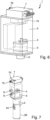
- In
Figur 5 ist schematisch eine Schnittdarstellung einer Vorrichtung 1 in einer weiteren Ausführung gezeigt, bei der das Gehäuse 5 an seiner Oberseite 50 mit einem Flansch 52 versehen ist. Auf dem Flansch 52 ist, bevorzugt unter Verwendung einer Dichtung 54, ein Ventilblock 7 aufgesetzt, welcher das Gehäuse 5 dann nach oben hin verschließt. Der Ventilblock 7 kann anstelle der Verschraubung mittels des Flansches 52 auch direkt mit dem Gehäuse 5 verschweißt werden. - Der Ventilblock 7 umfasst neben einer Pneumatikluftzufuhr 70 und einer Pneumatikluftabfuhr 72 auch mehrere Vorsteuerventile 74. Die Vorsteuerventile 74 sind zum Schalten unterschiedlicher pneumatischer Vorgänge innerhalb der Abfüllanlage vorgesehen. Durch das Aufbringen des Ventilblocks 7 quasi als obere "Gehäusewand" des Gehäuses 5 an dessen Oberseite 50 und das Verschrauben mit dem Flansch 52, bevorzugt unter Verwendung einer Dichtung 54, kann das Gehäuse 5 gegenüber der Umgebung abgedichtet werden und die Vorsteuerventile 74 bzw. deren Antriebe können in den Innenraum des Gehäuses 5 hereinragen. Auf diese Weise ergibt sich eine sehr kompakte Ausbildung der Vorrichtung 1 in Kombination mit dem Ventilblock 7 und die Vorsteuerventile 74 bzw. die Antriebe der Vorsteuerventile 74 können ebenfalls durch die Einrichtung 6 zum Reduzieren des Wärmeeintrags in die Steuerelektronik 4 von dem reduzierten Wärmeeintrag profitieren. Mit anderen Worten können auch die Vorsteuerventile 74 bzw. deren Aktuatoren innerhalb des Gehäuses 5 gekühlt werden, bei einem gleichzeitig kompakten Aufbau der Vorrichtung 1.
- Besonders bevorzugt ist es dabei, wenn die Vorsteuerventile 74 in das Gehäuse 5 hinein entlüften. Auch die Pneumatikluftabfuhr 72 kann in das Gehäuse 5 hinein geleitet werden. Auf diese Weise kann eine Reduzierung des Eintrags an Wärmeenergie in die Schaltelektronik 4 dadurch erreicht werden, dass die bereits im Ventilblock 7 verwendete Pneumatikluft in das Gehäuse 5 herein expandiert wird und auf diese Weise für die im Gehäuse 5 vorgesehenen Komponenten und insbesondere für die Schaltelektronik 4 zu einer Reduktion des Wärmeeintrags führt und für einen Abtransport der Wärmeenergie sorgt. Dadurch, dass die ohnehin vorhandene Abluft aus dem Ventilblock 7 verwendet wird, kann die Verwendung zusätzlicher Pneumatikluft eingespart werden.
- Bevorzugt fließt die Pneumatikluft durch das Gehäuse 5 und durch den Aktuator 3, also zwischen Rotor und Stator des Aktuators 3, hindurch, und dann durch einen Faltenbalg 28, welcher zur Abdichtung des Aktuators 3 gegenüber dem Füllprodukt vorgesehen ist, hindurch, um dann über eine den Ventilkegel 22 fixierende und entsprechend als Luftauslass 626 ausgebildete Schraube aus der Vorrichtung 1 abgeleitet zu werden. Der Luftfluss ist durch den Pfeil L angedeutet. Entsprechend durchströmt die Pneumatikluft nicht nur das Innere des Gehäuses 5, sondern auch den Aktuator 3 und Teile des Ventilkörpers 2, um auf diese Weise einen Abtransport von Wärmeenergie zu ermöglichen.
- In den
Figuren 6 und 7 wird der zuFigur 5 beschriebene Aufbau noch einmal schematisch in perspektivischen Darstellungen gezeigt. - Die Innenseiten des Gehäuses 5 können weiterhin auch mit einer schwarzen Beschichtung versehen sein, um eine erhöhte Wärmeabsorption zu ermöglichen und entsprechend einen Abtransport der in das Gehäuse eingetragenen Wärmeenergie nach außen hin zu ermöglichen.
- Weiterhin kann auch durch eine verbesserte Wärmeübertragung der vom Aktuator 3 erzeugten Wärmeenergie an die Wand des Gehäuses 5 erreicht werden, dass die über den Aktuator 3 in das Innere des Gehäuses 5 eingetragene Wärmeenergie über die Gehäusewand nach außen hin abtransportiert und abgestrahlt wird. Eine verbesserte Wärmeleitung kann beispielsweise über direkte metallische Verbindungen, Wärmeleitpads, Wärmeleitpaste oder eine entsprechende konstruktive Einrückung der Gehäusewand zum Aktuator 3 hin erreicht werden.
- Weiterhin kann auch die von dem Aktuator 3 eingetragene Wärmeenergie dadurch reduziert werden, dass der Aktuator 3 auf Grundlage des tatsächlich benötigten Drehmoments gesteuert wird, da üblicherweise die Faltenbälge 28 bei höheren Temperaturen weniger steif sind und entsprechend ein geringeres Drehmoment benötigt wird, so dass der Aktuator 3 dann mit weniger Energie betrieben werden kann und entsprechend weniger Wärme in den Innenraum des Gehäuses 5 einträgt.
-
- 1
- Vorrichtung zum Beeinflussen des Volumenstroms
- 100
- Abfüllanlage zum Abfüllen eines Füllprodukts in einen Behälter
- 110
- Füllventil zum Befüllen eines Behälters mit einem Füllprodukt
- 2
- Ventilkörper
- 20
- Ventilsitz
- 22
- Ventilkegel
- 24
- Zulauf
- 26
- Ablauf
- 28
- Faltenbalg
- 200
- dem Gehäuse zugewendetes Ende des Ventilkörpers
- 3
- Aktuator
- 4
- Steuerelektronik
- 5
- Gehäuse
- 50
- Oberseite
- 52
- Flansch
- 54
- Dichtung
- 6
- Einrichtung zum Reduzieren des Wärmeeintrags in die Steuerelektronik
- 60
- Kühlrippen
- 62
- Pneumatikluftzufuhr
- 620
- Öffnung reduzierten Querschnitts
- 622
- Steuerventil
- 624
- Temperatursensor
- 626
- Luftauslass
- 7
- Ventilblock
- 70
- Pneumatikluftzufuhr
- 72
- Pneumatikluftabfuhr
- 74
- Vorsteuerventil
- 8
- Anschluss für externe Steuerung
- 80
- Kommunikationsmodul
- 9
- Anschluss für weitere Sensoren
- 90
- Sensorelektronik
- F
- Füllproduktstrom
- W
- Wärmestrom
- L
- Luftstrom
Claims (10)
- Vorrichtung (1) zum Beeinflussen des Volumenstroms eines Füllprodukts in einer Abfüllanlage (100) zum Abfüllen von Füllprodukten, umfassend einen Ventilkörper (2) mit einem Ventilsitz (20) und einen relativ zu diesem bewegbaren Ventilkegel (22), einen Aktuator (3) zum Positionieren des Ventilkegels (22) bezüglich des Ventilsitzes (20), eine Steuerelektronik (4) zum Ansteuern des Aktuators (3), ein Gehäuse (5), welches direkt mit dem Ventilkörper (2) verbunden ist und in welchem der Aktuator (3) und die Steuerelektronik (4) angeordnet sind, sowie eine Einrichtung (6) zum Reduzieren eines Wärmeeintrags in die Steuerelektronik (4)
dadurch gekennzeichnet,
dass die Einrichtung (6) zum Reduzieren des Wärmeeintrags Kühlrippen (60) umfasst, welche an einem dem Gehäuse (5) zugewendeten Ende (200) des Ventilkörpers (2) ausgebildet sind, und/oder dass die Einrichtung (6) zum Reduzieren des Wärmeeintrags eine Pneumatikluftzufuhr (62) zum Einbringen von Pneumatikluft in das Gehäuse (5) umfasst. - Vorrichtung (1) gemäß Anspruch 1, dadurch gekennzeichnet, dass die Kühlrippen (60) in einem hygienischen Design ausgebildet sind.
- Vorrichtung (1) gemäß Anspruch 1 oder 2, dadurch gekennzeichnet, dass die Pneumatikluftzufuhr (62) ein Expansionsventil, ein Drosselventil oder eine Öffnung reduzierten Querschnitts (620) zum Zuführen expandierter Pneumatikluft in das Gehäuse (5) aufweist.
- Vorrichtung (1) gemäß einem der vorstehenden Ansprüche, dadurch gekennzeichnet, dass die Pneumatikluftzufuhr (62) so angeordnet ist, dass der austretende Pneumatikluftstrom (L) auf die Steuerelektronik (4) trifft.
- Vorrichtung (1) gemäß einem der vorstehenden Ansprüche, dadurch gekennzeichnet, dass die über die Pneumatikluftzufuhr (62) vorgenommen Zufuhr an Pneumatikluft mittels eines Steuerventils (622) anhand eines im Gehäuse (5) vorgesehenen Temperatursensors (624) geregelt ist.
- Vorrichtung (1) gemäß einem der vorstehenden Ansprüche, dadurch gekennzeichnet, dass das Gehäuse (5) einen Luftauslass (626) aufweist, welcher bevorzugt mit einem Rückschlagventil versehen ist.
- Vorrichtung (1) gemäß einem der vorstehenden Ansprüche, dadurch gekennzeichnet, dass an dem Gehäuse (5) ein Ventilblock (7) angeordnet ist und bevorzugt der Aktuator des Ventils, besonders bevorzugt der Aktuator eines Vorsteuerventils (74), in dem Gehäuse (5) aufgenommen ist.
- Vorrichtung (1) gemäß Anspruch 7
dadurch gekennzeichnet, dass der Ventilblock (7)
eine Wand des Gehäuses (5) ausbildet und bevorzugt mittels eines am Gehäuse (5) vorgesehenen Flanschs (52) mit dem Gehäuse (5) verbunden ist. - Vorrichtung (1) gemäß Anspruch 7 oder 8
dadurch gekennzeichnet, dass der
Ventilblock (7) so ausgebildet ist, dass die Pneumatikabluft der Ventile, bevorzugt der Vorsteuerventile (74), in das Gehäuse (5) geleitet wird. - Vorrichtung (1) gemäß einem der vorstehenden Ansprüche, dadurch gekennzeichnet, dass an dem Gehäuse (5) Sensorschnittstellen (9) zum Anschluss eines Durchflussmessers, einer Wägezelle und/oder eines Kurzschlusssensors vorgesehen sind und im Gehäuse (5) bevorzugt eine Sensorelektronik (90) aufgenommen ist.
Priority Applications (1)
| Application Number | Priority Date | Filing Date | Title |
|---|---|---|---|
| SI201731351T SI3519345T1 (sl) | 2016-09-29 | 2017-09-29 | Naprava za vplivanje na prostorninski pretok polnilnega izdelka v polnilnici |
Applications Claiming Priority (2)
| Application Number | Priority Date | Filing Date | Title |
|---|---|---|---|
| DE102016118474.8A DE102016118474A1 (de) | 2016-09-29 | 2016-09-29 | Vorrichtung zum Beeinflussen des Volumenstroms eines Füllprodukts in einer Abfüllanlage |
| PCT/EP2017/074768 WO2018060419A1 (de) | 2016-09-29 | 2017-09-29 | Vorrichtung zum beeinflussen des volumenstroms eines füllprodukts in einer abfüllanlage |
Publications (2)
| Publication Number | Publication Date |
|---|---|
| EP3519345A1 EP3519345A1 (de) | 2019-08-07 |
| EP3519345B1 true EP3519345B1 (de) | 2023-05-03 |
Family
ID=59982386
Family Applications (1)
| Application Number | Title | Priority Date | Filing Date |
|---|---|---|---|
| EP17777260.5A Active EP3519345B1 (de) | 2016-09-29 | 2017-09-29 | Vorrichtung zum beeinflussen des volumenstroms eines füllprodukts in einer abfüllanlage |
Country Status (7)
| Country | Link |
|---|---|
| US (1) | US11208311B2 (de) |
| EP (1) | EP3519345B1 (de) |
| JP (1) | JP2019529255A (de) |
| CN (1) | CN109790005B (de) |
| DE (1) | DE102016118474A1 (de) |
| SI (1) | SI3519345T1 (de) |
| WO (1) | WO2018060419A1 (de) |
Family Cites Families (31)
| Publication number | Priority date | Publication date | Assignee | Title |
|---|---|---|---|---|
| CH398229A (de) * | 1960-10-21 | 1965-08-31 | Danfoss Ved Ing M Clausen | Thermostatisches Ventil |
| DE1150299B (de) | 1961-03-13 | 1963-06-12 | Blendax Werke Schneider Co | Ventil zum Fuellen von Flaschen oder aehnlichen Behaeltern |
| US3926169A (en) * | 1974-06-21 | 1975-12-16 | Fuel Injection Dev Corp | Combined fuel vapor injector and igniter system for internal combustion engines |
| DE9311427U1 (de) * | 1993-07-31 | 1994-09-08 | Kronseder Maschf Krones | Vorrichtung zum Füllen von Gefäßen mit einer Flüssigkeit |
| DE29513031U1 (de) * | 1995-08-17 | 1996-09-12 | Kronseder Maschf Krones | Gefäßfüllmaschine |
| IT1293960B1 (it) * | 1997-06-20 | 1999-03-11 | Mbf Spa | Macchina riempitrice rotativa per il riempimento di contenitori con liquidi |
| US5975118A (en) * | 1997-10-24 | 1999-11-02 | Johnson Controls Technology | Adapter for mounting an actuator to a valve |
| DE19818762A1 (de) * | 1998-04-27 | 1999-10-28 | Khs Masch & Anlagenbau Ag | Füllsystem sowie Füllelement |
| DE10000793C1 (de) | 2000-01-11 | 2001-08-02 | Alfill Engineering Gmbh & Co K | Elektronisch gesteuertes Füllorgan mit Steuereinheit |
| FI120481B (fi) * | 2000-02-15 | 2009-10-30 | Tasowheel Oy | Järjestely toimilaitteen yhteydessä |
| FR2810098B1 (fr) | 2000-06-13 | 2004-04-23 | Inst Francais Du Petrole | Dispositif de visualisation adaptable a une conduite ou circulent des fluides charges de particules solides |
| US6427970B1 (en) * | 2001-03-16 | 2002-08-06 | Young & Franklin, Inc. | Heat dissipating voice coil activated valves |
| US6543481B2 (en) * | 2001-09-12 | 2003-04-08 | Mac Valves, Inc. | Pilot operated pneumatic valve |
| FR2844254B1 (fr) | 2002-09-10 | 2006-02-10 | Valois Sa | Valve de distribution de produit fluide et dispositif de distribution de produit fluide comportant une telle valve |
| DE502004003104D1 (de) * | 2003-06-23 | 2007-04-19 | Mann & Hummel Protec Gmbh | Unterdruckbehälter mit aktiver Schnellentleerungsventilsteuerung |
| US20060283518A1 (en) * | 2003-08-16 | 2006-12-21 | Krones Ag | Counter-pressure filling device and method of counter-pressure filling |
| DE102004015167B3 (de) * | 2004-03-27 | 2005-11-03 | Khs Maschinen- Und Anlagenbau Ag | Füllelement |
| DE102004017205A1 (de) * | 2004-04-10 | 2005-10-27 | Khs Maschinen- Und Anlagenbau Ag | Füllmaschine umlaufender Bauart |
| DE102005042784A1 (de) * | 2005-07-26 | 2007-02-01 | Bosch Rexroth Aktiengesellschaft | Ventilanordnung und Kühlvorrichtung |
| ITPR20070053A1 (it) * | 2007-07-04 | 2009-01-05 | Sbc Bottling & Canning S P A | Macchina riempitrice |
| EP2042431B1 (de) * | 2007-09-20 | 2011-01-05 | Mettler-Toledo AG | Dosiervorrichtung und Dosiereinheit mit elektrostatischem Verschluss |
| IT1393171B1 (it) * | 2009-02-13 | 2012-04-11 | Berchi Group S P A | Impianto di riempimento a caldo di bottiglie. |
| DE102009016322A1 (de) * | 2009-04-06 | 2010-10-07 | Khs Ag | Füllsystem |
| DE102010022874A1 (de) * | 2010-06-07 | 2011-12-08 | Khs Gmbh | Füllelement sowie Füllmaschine zum Füllen von Flaschen oder dergleichen Behältern |
| CN202510817U (zh) | 2012-03-29 | 2012-10-31 | 苏州市职业大学 | 一种外循环冷却式电磁阀 |
| DE102012211926A1 (de) | 2012-07-09 | 2014-01-09 | Krones Ag | Ventil umfassend Ventilstempel und Ventilgehäuse sowie ein Füller |
| DE102013102547A1 (de) * | 2013-03-13 | 2014-09-18 | Khs Gmbh | Verfahren sowie Füllmaschine zum Füllen von Dosen oder dgl. Behältern mit einem flüssigen Füllgut |
| JP6380401B2 (ja) | 2013-09-30 | 2018-08-29 | 日立金属株式会社 | 流量制御弁及びそれを用いた質量流量制御装置 |
| CN203594871U (zh) | 2013-12-02 | 2014-05-14 | 浙江富鼎自控阀门有限公司 | 新型气动调节阀 |
| DE102014114641A1 (de) | 2014-10-09 | 2016-04-14 | Krones Aktiengesellschaft | Vorrichtung zum Befüllen eines Behälters mit einem Füllprodukt |
| CN205013844U (zh) | 2015-09-15 | 2016-02-03 | 富阳市富恒仪表阀门有限公司 | 低温型气动薄膜单座调节阀 |
-
2016
- 2016-09-29 DE DE102016118474.8A patent/DE102016118474A1/de not_active Withdrawn
-
2017
- 2017-09-29 JP JP2018563623A patent/JP2019529255A/ja active Pending
- 2017-09-29 EP EP17777260.5A patent/EP3519345B1/de active Active
- 2017-09-29 US US16/306,869 patent/US11208311B2/en active Active
- 2017-09-29 WO PCT/EP2017/074768 patent/WO2018060419A1/de unknown
- 2017-09-29 CN CN201780059039.2A patent/CN109790005B/zh active Active
- 2017-09-29 SI SI201731351T patent/SI3519345T1/sl unknown
Also Published As
| Publication number | Publication date |
|---|---|
| SI3519345T1 (sl) | 2023-07-31 |
| DE102016118474A1 (de) | 2018-03-29 |
| CN109790005B (zh) | 2023-01-31 |
| JP2019529255A (ja) | 2019-10-17 |
| CN109790005A (zh) | 2019-05-21 |
| EP3519345A1 (de) | 2019-08-07 |
| WO2018060419A1 (de) | 2018-04-05 |
| US11208311B2 (en) | 2021-12-28 |
| US20210147207A1 (en) | 2021-05-20 |
Similar Documents
| Publication | Publication Date | Title |
|---|---|---|
| DE10350791A1 (de) | Tellerventil mit Heizvorrichtung | |
| DE102008022435A1 (de) | Ventilbaueinheit mit zwei Drehklappenventilen | |
| WO2011124475A2 (de) | Gehäuse mit erweitertem umgebungstemperaturbereich | |
| EP3376839A1 (de) | Kühlvorrichtung für elektronisches steuergerät | |
| EP2613097A1 (de) | Heizgerät | |
| DE102011081183A1 (de) | Ventil zur Steuerung von Volumenströmen | |
| CH693684A5 (de) | Heizbares Tellerventil. | |
| EP3519345B1 (de) | Vorrichtung zum beeinflussen des volumenstroms eines füllprodukts in einer abfüllanlage | |
| EP2299199A2 (de) | Wassererwärmer, insbesondere Warmwasserspeicher | |
| EP2180226B1 (de) | Modulares Fluidverteilsystem | |
| EP2634542A1 (de) | Kühlkompresse zur Kühlung eines Strahlungs-Detektors mittels einer Kühlflüssigkeit | |
| WO2004057280A1 (de) | Anschlussstück für fluidleitungen | |
| DE2937873C3 (de) | Anlageschaltung | |
| DE102015016786A1 (de) | Aktuatoreinheit sowie Baugruppeneinheit mit zumindest einer solchen Aktuatoreinheit und zumindest einer Massenstromregel- oder Ventileinheit | |
| EP2160086A1 (de) | Kühlvorrichtung zur Kühlung eines elektronischen Steuergeräts sowie ein elektronisches Steuergerät | |
| DE19845398C1 (de) | Heizung für Kraftfahrzeuge | |
| DE102014004509B4 (de) | Regelvorrichtung | |
| DE102015100272B3 (de) | Temperieranordnung für Messgeräte | |
| EP2570881B2 (de) | Temperaturregelvorrichtung, insbesondere Thermostatvorrichtung | |
| DE10354302B3 (de) | Strahlpumpe mit Bypass | |
| EP1717071B1 (de) | Modular aufbegautes Fahrzeugtemperiersystem | |
| DE202011105395U1 (de) | Regelungsvorrichtung zur Regelung einer Kühlleistung | |
| EP2175210A2 (de) | Heizgerät mit Abgasüberwachungseinrichtung | |
| DE102021214789A1 (de) | Elektroenergieübertragungsvorrichtung | |
| DE19653052A1 (de) | Heizungssystem mit Einzelraumregelung |
Legal Events
| Date | Code | Title | Description |
|---|---|---|---|
| STAA | Information on the status of an ep patent application or granted ep patent |
Free format text: STATUS: UNKNOWN |
|
| STAA | Information on the status of an ep patent application or granted ep patent |
Free format text: STATUS: THE INTERNATIONAL PUBLICATION HAS BEEN MADE |
|
| PUAI | Public reference made under article 153(3) epc to a published international application that has entered the european phase |
Free format text: ORIGINAL CODE: 0009012 |
|
| STAA | Information on the status of an ep patent application or granted ep patent |
Free format text: STATUS: REQUEST FOR EXAMINATION WAS MADE |
|
| 17P | Request for examination filed |
Effective date: 20181129 |
|
| AK | Designated contracting states |
Kind code of ref document: A1 Designated state(s): AL AT BE BG CH CY CZ DE DK EE ES FI FR GB GR HR HU IE IS IT LI LT LU LV MC MK MT NL NO PL PT RO RS SE SI SK SM TR |
|
| AX | Request for extension of the european patent |
Extension state: BA ME |
|
| DAV | Request for validation of the european patent (deleted) | ||
| DAX | Request for extension of the european patent (deleted) | ||
| RIC1 | Information provided on ipc code assigned before grant |
Ipc: F16K 41/10 20060101ALN20220503BHEP Ipc: F16K 37/00 20060101ALN20220503BHEP Ipc: F16K 49/00 20060101ALN20220503BHEP Ipc: B67C 3/28 20060101ALI20220503BHEP Ipc: B67C 3/26 20060101AFI20220503BHEP |
|
| GRAP | Despatch of communication of intention to grant a patent |
Free format text: ORIGINAL CODE: EPIDOSNIGR1 |
|
| STAA | Information on the status of an ep patent application or granted ep patent |
Free format text: STATUS: GRANT OF PATENT IS INTENDED |
|
| RIC1 | Information provided on ipc code assigned before grant |
Ipc: F16K 41/10 20060101ALN20220527BHEP Ipc: F16K 37/00 20060101ALN20220527BHEP Ipc: F16K 49/00 20060101ALN20220527BHEP Ipc: B67C 3/28 20060101ALI20220527BHEP Ipc: B67C 3/26 20060101AFI20220527BHEP |
|
| RIC1 | Information provided on ipc code assigned before grant |
Ipc: F16K 41/10 20060101ALN20220609BHEP Ipc: F16K 37/00 20060101ALN20220609BHEP Ipc: F16K 49/00 20060101ALN20220609BHEP Ipc: B67C 3/28 20060101ALI20220609BHEP Ipc: B67C 3/26 20060101AFI20220609BHEP |
|
| INTG | Intention to grant announced |
Effective date: 20220623 |
|
| GRAS | Grant fee paid |
Free format text: ORIGINAL CODE: EPIDOSNIGR3 |
|
| GRAJ | Information related to disapproval of communication of intention to grant by the applicant or resumption of examination proceedings by the epo deleted |
Free format text: ORIGINAL CODE: EPIDOSDIGR1 |
|
| GRAL | Information related to payment of fee for publishing/printing deleted |
Free format text: ORIGINAL CODE: EPIDOSDIGR3 |
|
| STAA | Information on the status of an ep patent application or granted ep patent |
Free format text: STATUS: REQUEST FOR EXAMINATION WAS MADE |
|
| GRAP | Despatch of communication of intention to grant a patent |
Free format text: ORIGINAL CODE: EPIDOSNIGR1 |
|
| STAA | Information on the status of an ep patent application or granted ep patent |
Free format text: STATUS: GRANT OF PATENT IS INTENDED |
|
| INTC | Intention to grant announced (deleted) | ||
| RIC1 | Information provided on ipc code assigned before grant |
Ipc: F16K 41/10 20060101ALN20221104BHEP Ipc: F16K 37/00 20060101ALN20221104BHEP Ipc: F16K 49/00 20060101ALN20221104BHEP Ipc: B67C 3/28 20060101ALI20221104BHEP Ipc: B67C 3/26 20060101AFI20221104BHEP |
|
| INTG | Intention to grant announced |
Effective date: 20221124 |
|
| GRAA | (expected) grant |
Free format text: ORIGINAL CODE: 0009210 |
|
| STAA | Information on the status of an ep patent application or granted ep patent |
Free format text: STATUS: THE PATENT HAS BEEN GRANTED |
|
| AK | Designated contracting states |
Kind code of ref document: B1 Designated state(s): AL AT BE BG CH CY CZ DE DK EE ES FI FR GB GR HR HU IE IS IT LI LT LU LV MC MK MT NL NO PL PT RO RS SE SI SK SM TR |
|
| REG | Reference to a national code |
Ref country code: GB Ref legal event code: FG4D Free format text: NOT ENGLISH |
|
| REG | Reference to a national code |
Ref country code: AT Ref legal event code: REF Ref document number: 1564468 Country of ref document: AT Kind code of ref document: T Effective date: 20230515 Ref country code: CH Ref legal event code: EP |
|
| REG | Reference to a national code |
Ref country code: DE Ref legal event code: R096 Ref document number: 502017014689 Country of ref document: DE |
|
| REG | Reference to a national code |
Ref country code: IE Ref legal event code: FG4D Free format text: LANGUAGE OF EP DOCUMENT: GERMAN |
|
| P01 | Opt-out of the competence of the unified patent court (upc) registered |
Effective date: 20230523 |
|
| REG | Reference to a national code |
Ref country code: LT Ref legal event code: MG9D |
|
| REG | Reference to a national code |
Ref country code: NL Ref legal event code: MP Effective date: 20230503 |
|
| PG25 | Lapsed in a contracting state [announced via postgrant information from national office to epo] |
Ref country code: SE Free format text: LAPSE BECAUSE OF FAILURE TO SUBMIT A TRANSLATION OF THE DESCRIPTION OR TO PAY THE FEE WITHIN THE PRESCRIBED TIME-LIMIT Effective date: 20230503 Ref country code: PT Free format text: LAPSE BECAUSE OF FAILURE TO SUBMIT A TRANSLATION OF THE DESCRIPTION OR TO PAY THE FEE WITHIN THE PRESCRIBED TIME-LIMIT Effective date: 20230904 Ref country code: NO Free format text: LAPSE BECAUSE OF FAILURE TO SUBMIT A TRANSLATION OF THE DESCRIPTION OR TO PAY THE FEE WITHIN THE PRESCRIBED TIME-LIMIT Effective date: 20230803 Ref country code: NL Free format text: LAPSE BECAUSE OF FAILURE TO SUBMIT A TRANSLATION OF THE DESCRIPTION OR TO PAY THE FEE WITHIN THE PRESCRIBED TIME-LIMIT Effective date: 20230503 Ref country code: ES Free format text: LAPSE BECAUSE OF FAILURE TO SUBMIT A TRANSLATION OF THE DESCRIPTION OR TO PAY THE FEE WITHIN THE PRESCRIBED TIME-LIMIT Effective date: 20230503 |
|
| PGFP | Annual fee paid to national office [announced via postgrant information from national office to epo] |
Ref country code: IT Payment date: 20230810 Year of fee payment: 7 |
|
| PG25 | Lapsed in a contracting state [announced via postgrant information from national office to epo] |
Ref country code: RS Free format text: LAPSE BECAUSE OF FAILURE TO SUBMIT A TRANSLATION OF THE DESCRIPTION OR TO PAY THE FEE WITHIN THE PRESCRIBED TIME-LIMIT Effective date: 20230503 Ref country code: PL Free format text: LAPSE BECAUSE OF FAILURE TO SUBMIT A TRANSLATION OF THE DESCRIPTION OR TO PAY THE FEE WITHIN THE PRESCRIBED TIME-LIMIT Effective date: 20230503 Ref country code: LV Free format text: LAPSE BECAUSE OF FAILURE TO SUBMIT A TRANSLATION OF THE DESCRIPTION OR TO PAY THE FEE WITHIN THE PRESCRIBED TIME-LIMIT Effective date: 20230503 Ref country code: LT Free format text: LAPSE BECAUSE OF FAILURE TO SUBMIT A TRANSLATION OF THE DESCRIPTION OR TO PAY THE FEE WITHIN THE PRESCRIBED TIME-LIMIT Effective date: 20230503 Ref country code: IS Free format text: LAPSE BECAUSE OF FAILURE TO SUBMIT A TRANSLATION OF THE DESCRIPTION OR TO PAY THE FEE WITHIN THE PRESCRIBED TIME-LIMIT Effective date: 20230903 Ref country code: HR Free format text: LAPSE BECAUSE OF FAILURE TO SUBMIT A TRANSLATION OF THE DESCRIPTION OR TO PAY THE FEE WITHIN THE PRESCRIBED TIME-LIMIT Effective date: 20230503 Ref country code: GR Free format text: LAPSE BECAUSE OF FAILURE TO SUBMIT A TRANSLATION OF THE DESCRIPTION OR TO PAY THE FEE WITHIN THE PRESCRIBED TIME-LIMIT Effective date: 20230804 |
|
| PGFP | Annual fee paid to national office [announced via postgrant information from national office to epo] |
Ref country code: SI Payment date: 20230815 Year of fee payment: 7 Ref country code: FR Payment date: 20230808 Year of fee payment: 7 Ref country code: DE Payment date: 20230802 Year of fee payment: 7 |
|
| PG25 | Lapsed in a contracting state [announced via postgrant information from national office to epo] |
Ref country code: FI Free format text: LAPSE BECAUSE OF FAILURE TO SUBMIT A TRANSLATION OF THE DESCRIPTION OR TO PAY THE FEE WITHIN THE PRESCRIBED TIME-LIMIT Effective date: 20230503 |
|
| PG25 | Lapsed in a contracting state [announced via postgrant information from national office to epo] |
Ref country code: SK Free format text: LAPSE BECAUSE OF FAILURE TO SUBMIT A TRANSLATION OF THE DESCRIPTION OR TO PAY THE FEE WITHIN THE PRESCRIBED TIME-LIMIT Effective date: 20230503 |
|
| PG25 | Lapsed in a contracting state [announced via postgrant information from national office to epo] |
Ref country code: SM Free format text: LAPSE BECAUSE OF FAILURE TO SUBMIT A TRANSLATION OF THE DESCRIPTION OR TO PAY THE FEE WITHIN THE PRESCRIBED TIME-LIMIT Effective date: 20230503 Ref country code: SK Free format text: LAPSE BECAUSE OF FAILURE TO SUBMIT A TRANSLATION OF THE DESCRIPTION OR TO PAY THE FEE WITHIN THE PRESCRIBED TIME-LIMIT Effective date: 20230503 Ref country code: RO Free format text: LAPSE BECAUSE OF FAILURE TO SUBMIT A TRANSLATION OF THE DESCRIPTION OR TO PAY THE FEE WITHIN THE PRESCRIBED TIME-LIMIT Effective date: 20230503 Ref country code: EE Free format text: LAPSE BECAUSE OF FAILURE TO SUBMIT A TRANSLATION OF THE DESCRIPTION OR TO PAY THE FEE WITHIN THE PRESCRIBED TIME-LIMIT Effective date: 20230503 Ref country code: DK Free format text: LAPSE BECAUSE OF FAILURE TO SUBMIT A TRANSLATION OF THE DESCRIPTION OR TO PAY THE FEE WITHIN THE PRESCRIBED TIME-LIMIT Effective date: 20230503 Ref country code: CZ Free format text: LAPSE BECAUSE OF FAILURE TO SUBMIT A TRANSLATION OF THE DESCRIPTION OR TO PAY THE FEE WITHIN THE PRESCRIBED TIME-LIMIT Effective date: 20230503 |
|
| REG | Reference to a national code |
Ref country code: DE Ref legal event code: R097 Ref document number: 502017014689 Country of ref document: DE |
|
| PLBE | No opposition filed within time limit |
Free format text: ORIGINAL CODE: 0009261 |
|
| STAA | Information on the status of an ep patent application or granted ep patent |
Free format text: STATUS: NO OPPOSITION FILED WITHIN TIME LIMIT |
|
| 26N | No opposition filed |
Effective date: 20240206 |