EP3519345B1 - Dispositif permettant d'agir sur le flux volumique d'un produit de remplissage dans une installation de mise en bouteille - Google Patents
Dispositif permettant d'agir sur le flux volumique d'un produit de remplissage dans une installation de mise en bouteille Download PDFInfo
- Publication number
- EP3519345B1 EP3519345B1 EP17777260.5A EP17777260A EP3519345B1 EP 3519345 B1 EP3519345 B1 EP 3519345B1 EP 17777260 A EP17777260 A EP 17777260A EP 3519345 B1 EP3519345 B1 EP 3519345B1
- Authority
- EP
- European Patent Office
- Prior art keywords
- housing
- valve
- pneumatic air
- filling
- control electronics
- Prior art date
- Legal status (The legal status is an assumption and is not a legal conclusion. Google has not performed a legal analysis and makes no representation as to the accuracy of the status listed.)
- Active
Links
- 238000001816 cooling Methods 0.000 claims description 27
- 238000013461 design Methods 0.000 claims description 12
- 230000001105 regulatory effect Effects 0.000 claims description 8
- 230000001276 controlling effect Effects 0.000 claims description 3
- 230000004941 influx Effects 0.000 claims 3
- 239000002699 waste material Substances 0.000 claims 1
- 235000013361 beverage Nutrition 0.000 description 12
- 238000000034 method Methods 0.000 description 9
- 238000005429 filling process Methods 0.000 description 7
- 238000004140 cleaning Methods 0.000 description 5
- 230000000694 effects Effects 0.000 description 4
- 239000000463 material Substances 0.000 description 4
- 239000000523 sample Substances 0.000 description 4
- 230000001954 sterilising effect Effects 0.000 description 4
- 238000004659 sterilization and disinfection Methods 0.000 description 4
- 238000004891 communication Methods 0.000 description 3
- 238000010276 construction Methods 0.000 description 2
- 238000010521 absorption reaction Methods 0.000 description 1
- 239000011248 coating agent Substances 0.000 description 1
- 238000000576 coating method Methods 0.000 description 1
- 230000001419 dependent effect Effects 0.000 description 1
- 238000011161 development Methods 0.000 description 1
- 230000018109 developmental process Effects 0.000 description 1
- 238000011143 downstream manufacturing Methods 0.000 description 1
- 238000007373 indentation Methods 0.000 description 1
- 238000009413 insulation Methods 0.000 description 1
- 230000010354 integration Effects 0.000 description 1
- 239000003973 paint Substances 0.000 description 1
- 230000005855 radiation Effects 0.000 description 1
- 230000035945 sensitivity Effects 0.000 description 1
- 238000012546 transfer Methods 0.000 description 1
- 238000011144 upstream manufacturing Methods 0.000 description 1
- 238000005303 weighing Methods 0.000 description 1
Images


Classifications
-
- B—PERFORMING OPERATIONS; TRANSPORTING
- B67—OPENING, CLOSING OR CLEANING BOTTLES, JARS OR SIMILAR CONTAINERS; LIQUID HANDLING
- B67C—CLEANING, FILLING WITH LIQUIDS OR SEMILIQUIDS, OR EMPTYING, OF BOTTLES, JARS, CANS, CASKS, BARRELS, OR SIMILAR CONTAINERS, NOT OTHERWISE PROVIDED FOR; FUNNELS
- B67C3/00—Bottling liquids or semiliquids; Filling jars or cans with liquids or semiliquids using bottling or like apparatus; Filling casks or barrels with liquids or semiliquids
- B67C3/02—Bottling liquids or semiliquids; Filling jars or cans with liquids or semiliquids using bottling or like apparatus
- B67C3/22—Details
- B67C3/28—Flow-control devices, e.g. using valves
- B67C3/286—Flow-control devices, e.g. using valves related to flow rate control, i.e. controlling slow and fast filling phases
-
- B—PERFORMING OPERATIONS; TRANSPORTING
- B67—OPENING, CLOSING OR CLEANING BOTTLES, JARS OR SIMILAR CONTAINERS; LIQUID HANDLING
- B67C—CLEANING, FILLING WITH LIQUIDS OR SEMILIQUIDS, OR EMPTYING, OF BOTTLES, JARS, CANS, CASKS, BARRELS, OR SIMILAR CONTAINERS, NOT OTHERWISE PROVIDED FOR; FUNNELS
- B67C3/00—Bottling liquids or semiliquids; Filling jars or cans with liquids or semiliquids using bottling or like apparatus; Filling casks or barrels with liquids or semiliquids
- B67C3/02—Bottling liquids or semiliquids; Filling jars or cans with liquids or semiliquids using bottling or like apparatus
- B67C3/22—Details
- B67C3/26—Filling-heads; Means for engaging filling-heads with bottle necks
-
- B—PERFORMING OPERATIONS; TRANSPORTING
- B67—OPENING, CLOSING OR CLEANING BOTTLES, JARS OR SIMILAR CONTAINERS; LIQUID HANDLING
- B67C—CLEANING, FILLING WITH LIQUIDS OR SEMILIQUIDS, OR EMPTYING, OF BOTTLES, JARS, CANS, CASKS, BARRELS, OR SIMILAR CONTAINERS, NOT OTHERWISE PROVIDED FOR; FUNNELS
- B67C3/00—Bottling liquids or semiliquids; Filling jars or cans with liquids or semiliquids using bottling or like apparatus; Filling casks or barrels with liquids or semiliquids
- B67C3/007—Applications of control, warning or safety devices in filling machinery
-
- B—PERFORMING OPERATIONS; TRANSPORTING
- B67—OPENING, CLOSING OR CLEANING BOTTLES, JARS OR SIMILAR CONTAINERS; LIQUID HANDLING
- B67C—CLEANING, FILLING WITH LIQUIDS OR SEMILIQUIDS, OR EMPTYING, OF BOTTLES, JARS, CANS, CASKS, BARRELS, OR SIMILAR CONTAINERS, NOT OTHERWISE PROVIDED FOR; FUNNELS
- B67C3/00—Bottling liquids or semiliquids; Filling jars or cans with liquids or semiliquids using bottling or like apparatus; Filling casks or barrels with liquids or semiliquids
- B67C3/02—Bottling liquids or semiliquids; Filling jars or cans with liquids or semiliquids using bottling or like apparatus
- B67C3/22—Details
- B67C3/28—Flow-control devices, e.g. using valves
-
- F—MECHANICAL ENGINEERING; LIGHTING; HEATING; WEAPONS; BLASTING
- F16—ENGINEERING ELEMENTS AND UNITS; GENERAL MEASURES FOR PRODUCING AND MAINTAINING EFFECTIVE FUNCTIONING OF MACHINES OR INSTALLATIONS; THERMAL INSULATION IN GENERAL
- F16K—VALVES; TAPS; COCKS; ACTUATING-FLOATS; DEVICES FOR VENTING OR AERATING
- F16K37/00—Special means in or on valves or other cut-off apparatus for indicating or recording operation thereof, or for enabling an alarm to be given
- F16K37/0025—Electrical or magnetic means
- F16K37/005—Electrical or magnetic means for measuring fluid parameters
-
- F—MECHANICAL ENGINEERING; LIGHTING; HEATING; WEAPONS; BLASTING
- F16—ENGINEERING ELEMENTS AND UNITS; GENERAL MEASURES FOR PRODUCING AND MAINTAINING EFFECTIVE FUNCTIONING OF MACHINES OR INSTALLATIONS; THERMAL INSULATION IN GENERAL
- F16K—VALVES; TAPS; COCKS; ACTUATING-FLOATS; DEVICES FOR VENTING OR AERATING
- F16K41/00—Spindle sealings
- F16K41/10—Spindle sealings with diaphragm, e.g. shaped as bellows or tube
-
- F—MECHANICAL ENGINEERING; LIGHTING; HEATING; WEAPONS; BLASTING
- F16—ENGINEERING ELEMENTS AND UNITS; GENERAL MEASURES FOR PRODUCING AND MAINTAINING EFFECTIVE FUNCTIONING OF MACHINES OR INSTALLATIONS; THERMAL INSULATION IN GENERAL
- F16K—VALVES; TAPS; COCKS; ACTUATING-FLOATS; DEVICES FOR VENTING OR AERATING
- F16K49/00—Means in or on valves for heating or cooling
- F16K49/005—Circulation means for a separate heat transfer fluid
-
- H—ELECTRICITY
- H05—ELECTRIC TECHNIQUES NOT OTHERWISE PROVIDED FOR
- H05K—PRINTED CIRCUITS; CASINGS OR CONSTRUCTIONAL DETAILS OF ELECTRIC APPARATUS; MANUFACTURE OF ASSEMBLAGES OF ELECTRICAL COMPONENTS
- H05K7/00—Constructional details common to different types of electric apparatus
- H05K7/20—Modifications to facilitate cooling, ventilating, or heating
- H05K7/20009—Modifications to facilitate cooling, ventilating, or heating using a gaseous coolant in electronic enclosures
- H05K7/20136—Forced ventilation, e.g. by fans
-
- H—ELECTRICITY
- H05—ELECTRIC TECHNIQUES NOT OTHERWISE PROVIDED FOR
- H05K—PRINTED CIRCUITS; CASINGS OR CONSTRUCTIONAL DETAILS OF ELECTRIC APPARATUS; MANUFACTURE OF ASSEMBLAGES OF ELECTRICAL COMPONENTS
- H05K7/00—Constructional details common to different types of electric apparatus
- H05K7/20—Modifications to facilitate cooling, ventilating, or heating
- H05K7/2039—Modifications to facilitate cooling, ventilating, or heating characterised by the heat transfer by conduction from the heat generating element to a dissipating body
- H05K7/20409—Outer radiating structures on heat dissipating housings, e.g. fins integrated with the housing
-
- H—ELECTRICITY
- H05—ELECTRIC TECHNIQUES NOT OTHERWISE PROVIDED FOR
- H05K—PRINTED CIRCUITS; CASINGS OR CONSTRUCTIONAL DETAILS OF ELECTRIC APPARATUS; MANUFACTURE OF ASSEMBLAGES OF ELECTRICAL COMPONENTS
- H05K7/00—Constructional details common to different types of electric apparatus
- H05K7/20—Modifications to facilitate cooling, ventilating, or heating
Definitions
- the present invention relates to a device for influencing the volume flow of a filling product in a bottling plant for filling a container with a filling product, for example for influencing the volume flow of the beverage to be filled when filling a beverage container with the beverage in a beverage bottling plant.
- Throttle valves are known for this purpose, which are switched into the filling product path between the filling product reservoir and the filling product outlet and by means of which the volume flow can be influenced.
- a valve which can be designed as a proportional valve and with which the volume flow of the filling product can be influenced. It is possible not only to switch between two different volumetric flows, i.e. between a first volumetric flow, in which the valve is fully open and a second volumetric flow, in which the valve is fully closed, but the proportional valve also makes it possible to switch between different or arbitrary set many different flow rates depending on the position of the valve cone relative to its valve seat.
- an actuator is provided in said proportional valve, by means of which different positions of the valve cone relative to the valve seat can be approached and in this way different volume flows can be adjusted.
- control electronics are provided, by means of which the actuator is actuated and which ensures that the volume flow required by a central controller is also provided by the respective individual proportional valve.
- a beverage bottling plant usually has a large number of bottling stations and each of these bottling stations is preceded by such a proportional valve in order to be able to control the volume flow which ultimately flows into the container to be filled according to the specifications of a central bottling control.
- a compact design of the proportional valve is aimed at by arranging the actuator and the control electronics in a housing directly connected to the valve body. Accordingly, the proportional valve can be placed in the beverage bottling plant as a compact unit.
- the WO 01/62059 A1 describes a valve with actuator for use in a hot environment.
- the DE 198 50 188 A1 describes an adapter for mounting an actuator to a valve.
- the EP 3 006 392 A2 describes a device for filling a container with a filling product.
- a device for influencing the volume flow of a filling product in a filling plant for filling filling products comprising a valve body with a valve seat and a valve cone movable relative thereto, an actuator for positioning the valve cone with respect to the valve seat, control electronics for controlling the actuator, and a housing which is connected directly to the valve body and in which the actuator and the control electronics are arranged.
- a device for reducing heat input into the control electronics is provided.
- the device for reducing the heat input into the control electronics is provided, the device for influencing the volume flow of the filling product, which is already compact in design by accommodating the control electronics in the housing and which is based on the provision of a central electronics box for accommodating the can do without the entire control electronics, can also be used in hot filling processes, since the heat input into the control electronics is reduced and negative effects on the control electronics can be avoided in this way.
- the device for reducing the heat input into the control electronics primarily serves to reduce the heat input emanating from the heated valve body.
- a device for influencing the volume flow can be provided in a compact manner and at the same time insensitivity to heat can be achieved, so that the device for influencing the volume flow, for example a proportional valve, can be used particularly flexibly in filling systems for filling products.
- the device for reducing the heat input into the control electronics also makes it possible to clean or sterilize the device for influencing the volume flow using high-temperature sterilization processes and high-temperature cleaning processes. Accordingly, the device can be used with all common filling methods and with all common cleaning and sterilization methods and at the same time provides a particularly compact structure.
- the device for reducing the heat input comprises cooling ribs, which are formed on an end of the valve body facing the housing. Accordingly can a heat flow, which is introduced into the valve body by the filling product or a sterilization medium, can be reduced in the direction of the housing. A heat flow from the valve body into the housing can be correspondingly reduced in that part of the heat introduced into the valve body via the filling product or the sterilization medium is released back to the environment via the cooling fins, and the heat flow from the valve body to the housing is correspondingly reduced .
- the reduction takes place on the one hand by the fact that heat is released to the environment via the cooling fins, and on the other hand the provision of cooling fins also reduces the total volume of material that can contribute to heat transport from the valve body to the housing.
- the cooling ribs in the valve body can either be arranged in the valve body itself, which also carries the valve seat and in which the valve cone is accommodated, or can be provided in an extension of the valve body, which can also be provided as a separate element of the valve body that is firmly connected to the valve body can be provided.
- the cooling fins are preferably formed in a hygienic design. Accordingly, the cooling fins do not have any undercuts, folds or hard edges in which foreign material could collect.
- the cooling ribs are preferably shaped in such a way that foreign material can be easily rinsed out or removed with a cleaning medium during the cleaning of the filling device.
- the device for reducing the heat input includes a pneumatic air supply for introducing pneumatic air into the housing.
- the pneumatic air which is already provided as the working medium in a filling device, is particularly preferably used to transport away the heat located in the housing.
- the pneumatic air supply particularly preferably has an expansion valve, a throttle valve or an opening with a reduced cross section for supplying expanded pneumatic air into the housing.
- the dried and pressurized pneumatic air is preferably expanded when entering the housing via the expansion valve, the throttle valve or the opening with a reduced cross-section, so that it cools down due to the Joule-Thomson effect and accordingly provides an additional cooling capacity to reduce the heat input into the control electronics.
- the pneumatic air is also applied to the control electronics in a targeted manner immediately after it has expanded in the housing, so that the control electronics are cooled before the pneumatic air, which is then still cool, gets through paint the rest of the case.
- the housing and the pneumatic air supply are geometrically designed in such a way that the air flow within the housing ensures that the expanded and correspondingly cold and dry pneumatic air first acts on the control electronics or other temperature-sensitive components within the housing and then flows through the rest of the housing and via a air outlet leaves the housing again.
- the pneumatic air is preferably discharged from the housing to the outside via defined channels, with an outlet valve or non-return valve ensuring that when the pneumatic air supply is switched off, moisture and foreign bodies do not enter the housing in an uncontrolled manner.
- the supply of pneumatic air via the pneumatic air supply is particularly preferably regulated or controlled by means of a control valve using a temperature sensor provided in the housing.
- a constant supply of pneumatic air can also be carried out.
- the pneumatic air introduced into the housing is routed from the housing through the valve body, in particular through the actuator, through a bellows shielding the plunger of the valve cone from the filling product and then via a defined outlet into the environment. Accordingly, the pneumatic air does not come into contact with the filling product, but serves both to reduce the heat input in the housing and in particular on the control electronics and, due to the flow through the actuator, also leads to cooling of the actuator.
- a valve block is arranged on the housing and preferably the actuator of the valve, particularly preferably the actuator of a pilot valve, is accommodated in the housing.
- a valve block in particular a valve block with pilot valves for further control of upstream or downstream processes of the bottling plant with the device for influencing the volume flow can also be designed in a compact manner.
- the pilot valves or the drives of the pilot valves can also be accommodated by the housing, so that the drives of the pilot valves can also benefit from the device for reducing the heat input into the control electronics.
- the housing can have an open flange on one side, instead of a closing plate, on which the valve block can be mounted.
- a seal is preferably provided between the valve block and the housing.
- the valve block can also be welded to the housing for integration into the housing.
- pilot valves and at least their drives are preferably also accommodated in the housing in this embodiment in order to benefit from the device for reducing the heat input into the control electronics.
- valve block is designed in such a way that the pneumatic exhaust air from the valves, preferably the pilot valves, is routed into the housing.
- the pilot valves also vent into the housing, so that when a container is filled with a filling product and a corresponding complete switching of the valves and pilot valves is carried out through a complete switching cycle, a pneumatic air flow can be provided through the housing by the exhaust air of the pneumatic system, which serves to reduce the heat input into the control electronics.
- further interfaces are preferably also integrated into the housing in order to be able to connect, for example, flow meters, load cells or short-circuit probes to the control electronics in such a way that regulation of the Device for influencing the volume flow can be performed on the basis of the corresponding sensor signals.
- the position of the valve tappet can be regulated via a flow sensor in such a way that a specific, intended flow is achieved.
- the same can also be achieved via the signal from a load cell or the signal from a short-circuit probe, whereby the exact process of filling the filling product into the container to be filled can be tracked via the load cell, but only the achievement of a certain filling level via a short-circuit probe can be used, for example, as a trigger for a reduction in the volume flow in the last filling section.
- the electronics which were previously arranged centrally, can essentially be relocated to the respective device for influencing the volume flow, so that the device can be constructed more compactly overall and the need for wiring can be reduced.
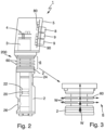
- figure 1 shows a device 1 for influencing the volume flow of a filling product in a bottling plant for bottling filling products according to the prior art, for example for bottling beverages in a beverage bottling plant.
- the device 1 comprises a valve body 2 which defines a valve seat 20 which is in communication with an inlet 24 and an outlet 26 for the filling product.
- a valve cone 22 is accommodated in the valve body 2, which can be lowered into the valve seat 22 with a seal or partial seal and lifted out of the valve seat 20 again, so that the volume flow of the filling product, which flows via the inlet 24 into the valve body 2 and into the valve seat 22 forming cavity occurs through the annular gap between Valve seat 20 and valve cone 22 flows and then leaves the valve body 2 again via the outlet 26 .
- the flow path of the filling product through the device 1 is in FIG figure 1 represented schematically by the arrow F.
- the volume flow of the filling product flowing through the device 1 can be controlled or regulated. If, for example, the valve cone 22 is completely lifted out of the valve seat 20, the filling product flows unhindered out of the outlet 26 and the volumetric flow is not throttled—apart from the flow resistance already predetermined by the device 1. If a throttling of the volume flow of the filling product is desired, the valve cone 22 can be lowered in the direction of the valve seat 20 by a corresponding amount in order to reduce the annular gap between the valve cone 22 and the valve seat 20 and thus achieve the desired reduced volume flow.
- an actuator 3 is provided, which can be provided, for example, in the form of an electric motor or another electromechanical drive, which is mechanically coupled to the valve cone 22, for example via a tappet, in such a way that when the actuator 3 is actuated, a corresponding positioning of the valve cone 22 relative to the valve seat 20 can be achieved.
- control electronics 4 are provided, which enable the actuator 3 to be controlled on the basis of external control signals, on the basis of logic provided by the control electronics 4 itself, or on the basis of a combination of both options.
- the control electronics 4 can process different external control signals, evaluate and process sensor signals and/or process feedback from the actuator 3 in order to ultimately position the valve cone 22 relative to the valve seat 20 and thus a volume flow according to the specifications of the filling process or the specifications to achieve a central filling control.
- the actuator 3 and the control electronics 4 are accommodated in a housing 5 which is connected directly to the valve body 2 and, according to the known embodiment, forms a seal with the valve body 2 .
- a housing 5 which is connected directly to the valve body 2 and, according to the known embodiment, forms a seal with the valve body 2 .
- valve body 2 has a device 6 for reducing the heat input into the control electronics 4 in the form of cooling fins 60 .
- the device 6 for reducing the heat input into the control electronics 4 serves in particular to reduce the heat input, which emanates from the valve body 2, into the control electronics 4.
- the provision of the cooling fins 60 reduces the flow of heat which flows from the valve body 2 to the housing 5 when a hot filling product flows through the valve body 2 . Correspondingly, the heat input into the control electronics 4 is reduced.
- the device for reducing the heat input 6 in the form of the cooling ribs 60 is preferably designed in such a way that the largest possible proportion of the thermal energy flowing from the valve body 2 in the direction of the housing 5 is already radiated by means of the cooling ribs 60 and accordingly does not flow into the housing 5 .
- the flow of heat and the radiation of thermal energy due to the cooling fins 60 is shown in the detailed illustration of the cooling fins 60 in figure 3 represented schematically by the arrows W.
- the cooling fins 60 are on accordingly that end 200 of the valve body 2 is provided, to which the housing 5 is connected.
- the cooling ribs 60 thus provide a kind of partial insulation between the valve body 2 and the housing 5 .
- the cooling fins 60 are, as for example from the detailed representation of the figure 3 to recognize, preferably designed so that undercuts and edges in which foreign material could accumulate can be avoided. In this way, a hygienic design can be provided, which is of particular importance in the field of bottling food and beverages.
- the surfaces of the cooling ribs 60 are correspondingly smooth and the shape is rounded in such a way that foreign matter cannot become lodged and can be rinsed out reliably and easily during a cleaning cycle.
- further electronic modules 90 for evaluating sensor signals supplied via an additional sensor interface 9 can also be provided in the housing 5 .
- communication modules 80 can also be provided for connecting the device 1 to a higher-level controller, for example to the system controller.
- the sensor interface 9 it is preferred for the sensor interface 9 to enable a connection to a flow meter, by means of which the position of the valve cone 22 relative to the valve seat 20 can then be regulated according to corresponding specifications for the volume flow.
- a connection to a weighing cell can also be provided, by means of which the volume flow flowing into the container to be filled can be determined and the position of the valve cone 22 relative to the valve seat 20 can be regulated accordingly.
- the sensor interface 9 can also be provided for connecting a short-circuit probe, which dips into the container to be filled in order to signal a certain filling threshold, from which a change in the volume flow flowing into the container should be made, for example towards the end of the filling process.
- a device for reducing the heat input 6 in the form of a pneumatic air supply 62 is provided on the housing 5 .
- Pneumatic air which is provided anyway as a working medium in a filling system for filling the filling product, can be introduced into the housing 5 via the pneumatic air supply 62 and heat can be transported away in this way, so that a reduction in the heat input into the control electronics 4 is also achieved here becomes.
- an air outlet 626 is preferably provided, which is arranged in such a way that the pneumatic air supplied via the pneumatic air supply 62 flows through the housing 5 evenly and preferably also as a function of the temperature sensitivity of the respective components within the housing 5 crossed out.
- the air outlet 626 is preferably provided with a non-return valve, so that when the pneumatic air supply 62 is switched off, the ingress of foreign bodies and moisture into the housing 5 is prevented.
- the air flow of the pneumatic air through the housing 5 and past the switching electronics 4 is indicated schematically by the arrow L in the figure.
- the pneumatic air supply 62 into the housing 5 can preferably be carried out via an expansion valve, a throttle valve or an opening with a reduced cross section 620 in such a way that the supplied and pressurized, dried pneumatic air from the pneumatic system of the bottling plant expands and the pneumatic air enters the housing 5 is cooled down accordingly.
- cooling is also explicitly provided at this point by the Joule-Thomson effect, which also serves to reduce the heat input into the control electronics 4 .
- the pneumatic air supply 62 and in particular the orientation of the opening with a reduced cross section 620 is selected in such a way that the expanded, dried and cooled by the expansion pneumatic air first hits the particularly temperature-sensitive components inside the housing 6, in particular the control electronics 4, so that Way a cooling and thus a reduction of the heat input into the control electronics 4 is achieved.
- the supply of pneumatic air via the pneumatic air supply 62 can be controlled or regulated via a control valve 622 .
- a control valve 622 In this case, either a constant quantity of pneumatic air can be provided and passed through the housing 5 in order to achieve the reduction accordingly to achieve the heat input into the control electronics 4.
- it can also be carried out by means of a temperature sensor 624 provided in the housing 5 via control or regulation of the supply of the quantity of pneumatic air.
- the supply of pneumatic air can be increased by means of the control valve 622 and if the temperature falls below certain threshold values, the supply of pneumatic air can be reduced.
- the temperature sensor 624 can preferably also be provided directly on the printed circuit board of the control electronics 4 in order to monitor the temperature of the control electronics 4 directly.
- the consumption of pneumatic air can be optimized and at the same time it can be ensured that the electronic control system 4 is always operated in an optimized temperature range and thus the heat input into the electronic control system 4 is reduced.
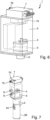
- FIG 5 a schematic sectional view of a device 1 is shown in a further embodiment, in which the housing 5 is provided with a flange 52 on its upper side 50 .
- a valve block 7 is placed on the flange 52, preferably using a seal 54, which then closes the housing 5 at the top.
- the valve block 7 can also be welded directly to the housing 5 instead of being screwed together using the flange 52 .
- the valve block 7 In addition to a pneumatic air supply 70 and a pneumatic air discharge 72, the valve block 7 also includes a plurality of pilot valves 74.
- the pilot valves 74 are provided for switching different pneumatic processes within the filling system.
- the pilot valves 74 vent into the housing 5 .
- the pneumatic air discharge 72 can also be routed into the housing 5 . In this way, a reduction in the input of thermal energy into the switching electronics 4 can be achieved in that the pneumatic air already used in the valve block 7 is expanded into the housing 5 and in this way for the components provided in the housing 5 and in particular for the switching electronics 4 leads to a reduction in the heat input and ensures that the heat energy is transported away. Because the exhaust air from the valve block 7 that is present anyway is used, the use of additional pneumatic air can be saved.
- the pneumatic air preferably flows through the housing 5 and through the actuator 3, i.e. between the rotor and stator of the actuator 3, and then through a bellows 28, which is provided to seal the actuator 3 from the filling product, and then via a The screw fixing the valve cone 22 and designed accordingly as an air outlet 626 to be derived from the device 1 .
- the air flow is indicated by the arrow L.
- the pneumatic air flows not only through the interior of the housing 5, but also through the actuator 3 and parts of the valve body 2, in order in this way to enable thermal energy to be transported away.
- the inner sides of the housing 5 can furthermore also be provided with a black coating in order to enable increased heat absorption and accordingly to enable the heat energy introduced into the housing to be transported away to the outside.
- improved heat transfer of the thermal energy generated by the actuator 3 to the wall of the housing 5 can also ensure that the thermal energy introduced into the interior of the housing 5 via the actuator 3 is transported away via the housing wall to the outside and radiated.
- Improved thermal conduction can be achieved, for example, via direct metallic connections, thermally conductive pads, thermally conductive paste or a corresponding structural indentation of the housing wall toward the actuator 3 .
- the thermal energy introduced by the actuator 3 can also be reduced in that the actuator 3 is controlled on the basis of the torque actually required because the bellows 28 are usually less stiff at higher temperatures and a correspondingly lower torque is required, so that the actuator 3 can then be operated with less energy and correspondingly less heat enters the interior of the housing 5 .
Landscapes
- Engineering & Computer Science (AREA)
- General Engineering & Computer Science (AREA)
- Physics & Mathematics (AREA)
- Mechanical Engineering (AREA)
- Microelectronics & Electronic Packaging (AREA)
- Thermal Sciences (AREA)
- Fluid Mechanics (AREA)
- Filling Of Jars Or Cans And Processes For Cleaning And Sealing Jars (AREA)
- Basic Packing Technique (AREA)
- Lift Valve (AREA)
- Valve Housings (AREA)
Claims (10)
- Dispositif (1) pour agir sur le flux volumique d'un produit de remplissage dans une installation de mise en bouteille (100) pour la mise en bouteille de produits de remplissage, comprenant un corps de soupape (2) doté d'un siège de soupape (20) et un cône de soupape (22) mobile par rapport à celui-ci, un actionneur (3) pour positionner le cône de soupape (22) par référence au siège de soupape (20), une électronique de commande (4) pour commander l'actionneur (3), un boîtier (5) qui est relié directement au corps de soupape (2) et dans lequel sont agencés l'actionneur (3) et l'électronique de commande (4), ainsi qu'un appareil (6) pour réduire une pénétration de chaleur dans l'électronique de commande (4);
caractérisé en ce que
l'appareil (6) pour réduire la pénétration de chaleur comprend des ailettes de refroidissement (60) qui sont formées au niveau d'une extrémité (200) du corps de soupape (2) tournée vers le boîtier (5), et/ou en ce que l'appareil (6) pour réduire la pénétration de chaleur comprend une alimentation en air pneumatique (62) pour introduire de l'air pneumatique dans le boîtier (5). - Dispositif (1) selon la revendication 1, caractérisé en ce que les ailettes de refroidissement (60) sont formées selon une conception hygiénique.
- Dispositif (1) selon la revendication 1 ou 2, caractérisé en ce que l'alimentation en air pneumatique (62) présente une soupape de détente, une soupape d'étranglement ou une ouverture de section transversale réduite (620) pour alimenter de l'air pneumatique détendu par expansion dans le boîtier (5).
- Dispositif (1) selon l'une quelconque des revendications précédentes, caractérisé en ce que l'alimentation en air pneumatique (62) est agencée de telle manière que le flux d'air pneumatique sortant (L) rencontre l'électronique de commande (4).
- Dispositif (1) selon l'une quelconque des revendications précédentes, caractérisé en ce que l'air pneumatique alimenté apporté via l'alimentation en air pneumatique (62) est régulée au moyen d'une soupape de commande (622) à l'aide d'un capteur de température (624) prévu dans le boîtier (5).
- Dispositif (1) selon l'une quelconque des revendications précédentes, caractérisé en ce que le boîtier (5) présente une sortie d'air (626), qui est de préférence munie d'un clapet anti-retour.
- Dispositif (1) selon l'une quelconque des revendications précédentes, caractérisé en ce qu'un bloc de soupapes (7) est agencé au niveau du boîtier (5) et de préférence l'actionneur de la soupape, le plus préférentiellement l'actionneur d'une soupape pilote (74) est reçu dans le boîtier (5).
- Dispositif (1) selon la revendication 7 caractérisé en ce que le bloc de soupapes (7) forme une paroi du boîtier (5) et est de préférence relié au boîtier (5) au moyen d'une bride (52) prévue au niveau du boîtier (5).
- Dispositif (1) selon la revendication 7 ou 8 caractérisé en ce que le bloc de soupapes (7) est conçu de sorte que l'échappement d'air pneumatique des soupapes, de préférence des soupapes pilotes (74), est dirigé dans le boîtier (5).
- Dispositif (1) selon l'une quelconque des revendications précédentes, caractérisé en ce que des interfaces de capteur (9) pour connecter un débitmètre, une cellule de charge et/ou un capteur de court-circuit sont prévues au niveau du boîtier (5) et une électronique de capteur (90) est de préférence reçue dans le boîtier (5).
Priority Applications (1)
| Application Number | Priority Date | Filing Date | Title |
|---|---|---|---|
| SI201731351T SI3519345T1 (sl) | 2016-09-29 | 2017-09-29 | Naprava za vplivanje na prostorninski pretok polnilnega izdelka v polnilnici |
Applications Claiming Priority (2)
| Application Number | Priority Date | Filing Date | Title |
|---|---|---|---|
| DE102016118474.8A DE102016118474A1 (de) | 2016-09-29 | 2016-09-29 | Vorrichtung zum Beeinflussen des Volumenstroms eines Füllprodukts in einer Abfüllanlage |
| PCT/EP2017/074768 WO2018060419A1 (fr) | 2016-09-29 | 2017-09-29 | Dispositif permettant d'agir sur le flux volumique d'un produit de remplissage dans une installation de mise en bouteille |
Publications (2)
| Publication Number | Publication Date |
|---|---|
| EP3519345A1 EP3519345A1 (fr) | 2019-08-07 |
| EP3519345B1 true EP3519345B1 (fr) | 2023-05-03 |
Family
ID=59982386
Family Applications (1)
| Application Number | Title | Priority Date | Filing Date |
|---|---|---|---|
| EP17777260.5A Active EP3519345B1 (fr) | 2016-09-29 | 2017-09-29 | Dispositif permettant d'agir sur le flux volumique d'un produit de remplissage dans une installation de mise en bouteille |
Country Status (7)
| Country | Link |
|---|---|
| US (1) | US11208311B2 (fr) |
| EP (1) | EP3519345B1 (fr) |
| JP (1) | JP2019529255A (fr) |
| CN (1) | CN109790005B (fr) |
| DE (1) | DE102016118474A1 (fr) |
| SI (1) | SI3519345T1 (fr) |
| WO (1) | WO2018060419A1 (fr) |
Family Cites Families (31)
| Publication number | Priority date | Publication date | Assignee | Title |
|---|---|---|---|---|
| CH398229A (de) * | 1960-10-21 | 1965-08-31 | Danfoss Ved Ing M Clausen | Thermostatisches Ventil |
| DE1150299B (de) | 1961-03-13 | 1963-06-12 | Blendax Werke Schneider Co | Ventil zum Fuellen von Flaschen oder aehnlichen Behaeltern |
| US3926169A (en) * | 1974-06-21 | 1975-12-16 | Fuel Injection Dev Corp | Combined fuel vapor injector and igniter system for internal combustion engines |
| DE9311427U1 (de) * | 1993-07-31 | 1994-09-08 | Kronseder Maschf Krones | Vorrichtung zum Füllen von Gefäßen mit einer Flüssigkeit |
| DE29513031U1 (de) * | 1995-08-17 | 1996-09-12 | Kronseder Maschf Krones | Gefäßfüllmaschine |
| IT1293960B1 (it) * | 1997-06-20 | 1999-03-11 | Mbf Spa | Macchina riempitrice rotativa per il riempimento di contenitori con liquidi |
| US5975118A (en) | 1997-10-24 | 1999-11-02 | Johnson Controls Technology | Adapter for mounting an actuator to a valve |
| DE19818762A1 (de) * | 1998-04-27 | 1999-10-28 | Khs Masch & Anlagenbau Ag | Füllsystem sowie Füllelement |
| DE10000793C1 (de) | 2000-01-11 | 2001-08-02 | Alfill Engineering Gmbh & Co K | Elektronisch gesteuertes Füllorgan mit Steuereinheit |
| FI120481B (fi) * | 2000-02-15 | 2009-10-30 | Tasowheel Oy | Järjestely toimilaitteen yhteydessä |
| FR2810098B1 (fr) * | 2000-06-13 | 2004-04-23 | Inst Francais Du Petrole | Dispositif de visualisation adaptable a une conduite ou circulent des fluides charges de particules solides |
| US6427970B1 (en) * | 2001-03-16 | 2002-08-06 | Young & Franklin, Inc. | Heat dissipating voice coil activated valves |
| US6543481B2 (en) * | 2001-09-12 | 2003-04-08 | Mac Valves, Inc. | Pilot operated pneumatic valve |
| FR2844254B1 (fr) * | 2002-09-10 | 2006-02-10 | Valois Sa | Valve de distribution de produit fluide et dispositif de distribution de produit fluide comportant une telle valve |
| DE502004003104D1 (de) * | 2003-06-23 | 2007-04-19 | Mann & Hummel Protec Gmbh | Unterdruckbehälter mit aktiver Schnellentleerungsventilsteuerung |
| CN1835886A (zh) * | 2003-08-16 | 2006-09-20 | 克罗内斯股份公司 | 背压灌装设备和用于背压灌装的方法 |
| DE102004015167B3 (de) * | 2004-03-27 | 2005-11-03 | Khs Maschinen- Und Anlagenbau Ag | Füllelement |
| DE102004017205A1 (de) * | 2004-04-10 | 2005-10-27 | Khs Maschinen- Und Anlagenbau Ag | Füllmaschine umlaufender Bauart |
| DE102005042784A1 (de) * | 2005-07-26 | 2007-02-01 | Bosch Rexroth Aktiengesellschaft | Ventilanordnung und Kühlvorrichtung |
| ITPR20070053A1 (it) * | 2007-07-04 | 2009-01-05 | Sbc Bottling & Canning S P A | Macchina riempitrice |
| EP2042431B1 (fr) * | 2007-09-20 | 2011-01-05 | Mettler-Toledo AG | Dispositif de dosage et unité de dosage dotée d'une fermeture électrostatique |
| IT1393171B1 (it) * | 2009-02-13 | 2012-04-11 | Berchi Group S P A | Impianto di riempimento a caldo di bottiglie. |
| DE102009016322A1 (de) * | 2009-04-06 | 2010-10-07 | Khs Ag | Füllsystem |
| DE102010022874A1 (de) * | 2010-06-07 | 2011-12-08 | Khs Gmbh | Füllelement sowie Füllmaschine zum Füllen von Flaschen oder dergleichen Behältern |
| CN202510817U (zh) * | 2012-03-29 | 2012-10-31 | 苏州市职业大学 | 一种外循环冷却式电磁阀 |
| DE102012211926A1 (de) | 2012-07-09 | 2014-01-09 | Krones Ag | Ventil umfassend Ventilstempel und Ventilgehäuse sowie ein Füller |
| DE102013102547A1 (de) * | 2013-03-13 | 2014-09-18 | Khs Gmbh | Verfahren sowie Füllmaschine zum Füllen von Dosen oder dgl. Behältern mit einem flüssigen Füllgut |
| KR102079533B1 (ko) * | 2013-09-30 | 2020-02-21 | 히타치 긴조쿠 가부시키가이샤 | 유량 제어 밸브 및 그것을 사용한 질량 유량 제어 장치 |
| CN203594871U (zh) * | 2013-12-02 | 2014-05-14 | 浙江富鼎自控阀门有限公司 | 新型气动调节阀 |
| DE102014114641A1 (de) * | 2014-10-09 | 2016-04-14 | Krones Aktiengesellschaft | Vorrichtung zum Befüllen eines Behälters mit einem Füllprodukt |
| CN205013844U (zh) * | 2015-09-15 | 2016-02-03 | 富阳市富恒仪表阀门有限公司 | 低温型气动薄膜单座调节阀 |
-
2016
- 2016-09-29 DE DE102016118474.8A patent/DE102016118474A1/de not_active Withdrawn
-
2017
- 2017-09-29 SI SI201731351T patent/SI3519345T1/sl unknown
- 2017-09-29 US US16/306,869 patent/US11208311B2/en active Active
- 2017-09-29 WO PCT/EP2017/074768 patent/WO2018060419A1/fr unknown
- 2017-09-29 EP EP17777260.5A patent/EP3519345B1/fr active Active
- 2017-09-29 CN CN201780059039.2A patent/CN109790005B/zh active Active
- 2017-09-29 JP JP2018563623A patent/JP2019529255A/ja active Pending
Also Published As
| Publication number | Publication date |
|---|---|
| JP2019529255A (ja) | 2019-10-17 |
| US11208311B2 (en) | 2021-12-28 |
| US20210147207A1 (en) | 2021-05-20 |
| SI3519345T1 (sl) | 2023-07-31 |
| CN109790005B (zh) | 2023-01-31 |
| EP3519345A1 (fr) | 2019-08-07 |
| WO2018060419A1 (fr) | 2018-04-05 |
| DE102016118474A1 (de) | 2018-03-29 |
| CN109790005A (zh) | 2019-05-21 |
Similar Documents
| Publication | Publication Date | Title |
|---|---|---|
| DE10350791A1 (de) | Tellerventil mit Heizvorrichtung | |
| DE102008022435A1 (de) | Ventilbaueinheit mit zwei Drehklappenventilen | |
| WO2011124475A2 (fr) | Boîtier avec une plage de température ambiante élargie | |
| EP3376839A1 (fr) | Dispositif de refroidissement pour appareil de commande électronique | |
| DE102011081183A1 (de) | Ventil zur Steuerung von Volumenströmen | |
| CH693684A5 (de) | Heizbares Tellerventil. | |
| WO2008055551A1 (fr) | Installation de chauffage ou de réfrigération | |
| EP3519345B1 (fr) | Dispositif permettant d'agir sur le flux volumique d'un produit de remplissage dans une installation de mise en bouteille | |
| EP2634542A1 (fr) | Compresse destinée au refroidissement d'un détecteur de rayonnement à l'aide d'un fluide de refroidissement | |
| EP2299199A2 (fr) | Dispositif de chauffage d'eau, notamment accumulateur d'eau chaude | |
| WO2004057280A1 (fr) | Element de raccordement pour conduites fluidiques | |
| EP1645822A2 (fr) | Procedé et unité d'interface pour l'alimentation et l'évacuation d'un réfrigérant vers ou à partir d'une unité de consommation | |
| DE2937873C3 (de) | Anlageschaltung | |
| DE102015016786A1 (de) | Aktuatoreinheit sowie Baugruppeneinheit mit zumindest einer solchen Aktuatoreinheit und zumindest einer Massenstromregel- oder Ventileinheit | |
| EP2160086A1 (fr) | Dispositif de refroidissement destiné au refroidissement d'un appareil de commande électronique et appareil de commande électronique | |
| DE19845398C1 (de) | Heizung für Kraftfahrzeuge | |
| DE102014004509B4 (de) | Regelvorrichtung | |
| DE10129203B4 (de) | Heizsystem und Verfahren zum Beeinflussen von Luftströmungen in einem Heizsystem | |
| DE102015100272B3 (de) | Temperieranordnung für Messgeräte | |
| EP2570881B2 (fr) | Dispositif de régulation de température, en particulier un dispositif thermostatique | |
| DE102012001839A1 (de) | Vorrichtung und Verfahren zur Abgaswärmenutzung | |
| EP1717071B1 (fr) | Système modulaire de climatisation de véhicule | |
| DE202011105395U1 (de) | Regelungsvorrichtung zur Regelung einer Kühlleistung | |
| EP2175210A2 (fr) | Appareil de chauffage doté d'un dispositif de surveillance des gaz d'échappement | |
| DE102021214789A1 (de) | Elektroenergieübertragungsvorrichtung |
Legal Events
| Date | Code | Title | Description |
|---|---|---|---|
| STAA | Information on the status of an ep patent application or granted ep patent |
Free format text: STATUS: UNKNOWN |
|
| STAA | Information on the status of an ep patent application or granted ep patent |
Free format text: STATUS: THE INTERNATIONAL PUBLICATION HAS BEEN MADE |
|
| PUAI | Public reference made under article 153(3) epc to a published international application that has entered the european phase |
Free format text: ORIGINAL CODE: 0009012 |
|
| STAA | Information on the status of an ep patent application or granted ep patent |
Free format text: STATUS: REQUEST FOR EXAMINATION WAS MADE |
|
| 17P | Request for examination filed |
Effective date: 20181129 |
|
| AK | Designated contracting states |
Kind code of ref document: A1 Designated state(s): AL AT BE BG CH CY CZ DE DK EE ES FI FR GB GR HR HU IE IS IT LI LT LU LV MC MK MT NL NO PL PT RO RS SE SI SK SM TR |
|
| AX | Request for extension of the european patent |
Extension state: BA ME |
|
| DAV | Request for validation of the european patent (deleted) | ||
| DAX | Request for extension of the european patent (deleted) | ||
| RIC1 | Information provided on ipc code assigned before grant |
Ipc: F16K 41/10 20060101ALN20220503BHEP Ipc: F16K 37/00 20060101ALN20220503BHEP Ipc: F16K 49/00 20060101ALN20220503BHEP Ipc: B67C 3/28 20060101ALI20220503BHEP Ipc: B67C 3/26 20060101AFI20220503BHEP |
|
| GRAP | Despatch of communication of intention to grant a patent |
Free format text: ORIGINAL CODE: EPIDOSNIGR1 |
|
| STAA | Information on the status of an ep patent application or granted ep patent |
Free format text: STATUS: GRANT OF PATENT IS INTENDED |
|
| RIC1 | Information provided on ipc code assigned before grant |
Ipc: F16K 41/10 20060101ALN20220527BHEP Ipc: F16K 37/00 20060101ALN20220527BHEP Ipc: F16K 49/00 20060101ALN20220527BHEP Ipc: B67C 3/28 20060101ALI20220527BHEP Ipc: B67C 3/26 20060101AFI20220527BHEP |
|
| RIC1 | Information provided on ipc code assigned before grant |
Ipc: F16K 41/10 20060101ALN20220609BHEP Ipc: F16K 37/00 20060101ALN20220609BHEP Ipc: F16K 49/00 20060101ALN20220609BHEP Ipc: B67C 3/28 20060101ALI20220609BHEP Ipc: B67C 3/26 20060101AFI20220609BHEP |
|
| INTG | Intention to grant announced |
Effective date: 20220623 |
|
| GRAS | Grant fee paid |
Free format text: ORIGINAL CODE: EPIDOSNIGR3 |
|
| GRAJ | Information related to disapproval of communication of intention to grant by the applicant or resumption of examination proceedings by the epo deleted |
Free format text: ORIGINAL CODE: EPIDOSDIGR1 |
|
| GRAL | Information related to payment of fee for publishing/printing deleted |
Free format text: ORIGINAL CODE: EPIDOSDIGR3 |
|
| STAA | Information on the status of an ep patent application or granted ep patent |
Free format text: STATUS: REQUEST FOR EXAMINATION WAS MADE |
|
| GRAP | Despatch of communication of intention to grant a patent |
Free format text: ORIGINAL CODE: EPIDOSNIGR1 |
|
| STAA | Information on the status of an ep patent application or granted ep patent |
Free format text: STATUS: GRANT OF PATENT IS INTENDED |
|
| INTC | Intention to grant announced (deleted) | ||
| RIC1 | Information provided on ipc code assigned before grant |
Ipc: F16K 41/10 20060101ALN20221104BHEP Ipc: F16K 37/00 20060101ALN20221104BHEP Ipc: F16K 49/00 20060101ALN20221104BHEP Ipc: B67C 3/28 20060101ALI20221104BHEP Ipc: B67C 3/26 20060101AFI20221104BHEP |
|
| INTG | Intention to grant announced |
Effective date: 20221124 |
|
| GRAA | (expected) grant |
Free format text: ORIGINAL CODE: 0009210 |
|
| STAA | Information on the status of an ep patent application or granted ep patent |
Free format text: STATUS: THE PATENT HAS BEEN GRANTED |
|
| AK | Designated contracting states |
Kind code of ref document: B1 Designated state(s): AL AT BE BG CH CY CZ DE DK EE ES FI FR GB GR HR HU IE IS IT LI LT LU LV MC MK MT NL NO PL PT RO RS SE SI SK SM TR |
|
| REG | Reference to a national code |
Ref country code: GB Ref legal event code: FG4D Free format text: NOT ENGLISH |
|
| REG | Reference to a national code |
Ref country code: AT Ref legal event code: REF Ref document number: 1564468 Country of ref document: AT Kind code of ref document: T Effective date: 20230515 Ref country code: CH Ref legal event code: EP |
|
| REG | Reference to a national code |
Ref country code: DE Ref legal event code: R096 Ref document number: 502017014689 Country of ref document: DE |
|
| REG | Reference to a national code |
Ref country code: IE Ref legal event code: FG4D Free format text: LANGUAGE OF EP DOCUMENT: GERMAN |
|
| P01 | Opt-out of the competence of the unified patent court (upc) registered |
Effective date: 20230523 |
|
| REG | Reference to a national code |
Ref country code: LT Ref legal event code: MG9D |
|
| REG | Reference to a national code |
Ref country code: NL Ref legal event code: MP Effective date: 20230503 |
|
| PG25 | Lapsed in a contracting state [announced via postgrant information from national office to epo] |
Ref country code: SE Free format text: LAPSE BECAUSE OF FAILURE TO SUBMIT A TRANSLATION OF THE DESCRIPTION OR TO PAY THE FEE WITHIN THE PRESCRIBED TIME-LIMIT Effective date: 20230503 Ref country code: PT Free format text: LAPSE BECAUSE OF FAILURE TO SUBMIT A TRANSLATION OF THE DESCRIPTION OR TO PAY THE FEE WITHIN THE PRESCRIBED TIME-LIMIT Effective date: 20230904 Ref country code: NO Free format text: LAPSE BECAUSE OF FAILURE TO SUBMIT A TRANSLATION OF THE DESCRIPTION OR TO PAY THE FEE WITHIN THE PRESCRIBED TIME-LIMIT Effective date: 20230803 Ref country code: NL Free format text: LAPSE BECAUSE OF FAILURE TO SUBMIT A TRANSLATION OF THE DESCRIPTION OR TO PAY THE FEE WITHIN THE PRESCRIBED TIME-LIMIT Effective date: 20230503 Ref country code: ES Free format text: LAPSE BECAUSE OF FAILURE TO SUBMIT A TRANSLATION OF THE DESCRIPTION OR TO PAY THE FEE WITHIN THE PRESCRIBED TIME-LIMIT Effective date: 20230503 |
|
| PGFP | Annual fee paid to national office [announced via postgrant information from national office to epo] |
Ref country code: IT Payment date: 20230810 Year of fee payment: 7 |
|
| PG25 | Lapsed in a contracting state [announced via postgrant information from national office to epo] |
Ref country code: RS Free format text: LAPSE BECAUSE OF FAILURE TO SUBMIT A TRANSLATION OF THE DESCRIPTION OR TO PAY THE FEE WITHIN THE PRESCRIBED TIME-LIMIT Effective date: 20230503 Ref country code: PL Free format text: LAPSE BECAUSE OF FAILURE TO SUBMIT A TRANSLATION OF THE DESCRIPTION OR TO PAY THE FEE WITHIN THE PRESCRIBED TIME-LIMIT Effective date: 20230503 Ref country code: LV Free format text: LAPSE BECAUSE OF FAILURE TO SUBMIT A TRANSLATION OF THE DESCRIPTION OR TO PAY THE FEE WITHIN THE PRESCRIBED TIME-LIMIT Effective date: 20230503 Ref country code: LT Free format text: LAPSE BECAUSE OF FAILURE TO SUBMIT A TRANSLATION OF THE DESCRIPTION OR TO PAY THE FEE WITHIN THE PRESCRIBED TIME-LIMIT Effective date: 20230503 Ref country code: IS Free format text: LAPSE BECAUSE OF FAILURE TO SUBMIT A TRANSLATION OF THE DESCRIPTION OR TO PAY THE FEE WITHIN THE PRESCRIBED TIME-LIMIT Effective date: 20230903 Ref country code: HR Free format text: LAPSE BECAUSE OF FAILURE TO SUBMIT A TRANSLATION OF THE DESCRIPTION OR TO PAY THE FEE WITHIN THE PRESCRIBED TIME-LIMIT Effective date: 20230503 Ref country code: GR Free format text: LAPSE BECAUSE OF FAILURE TO SUBMIT A TRANSLATION OF THE DESCRIPTION OR TO PAY THE FEE WITHIN THE PRESCRIBED TIME-LIMIT Effective date: 20230804 |
|
| PGFP | Annual fee paid to national office [announced via postgrant information from national office to epo] |
Ref country code: SI Payment date: 20230815 Year of fee payment: 7 Ref country code: FR Payment date: 20230808 Year of fee payment: 7 Ref country code: DE Payment date: 20230802 Year of fee payment: 7 |
|
| PG25 | Lapsed in a contracting state [announced via postgrant information from national office to epo] |
Ref country code: FI Free format text: LAPSE BECAUSE OF FAILURE TO SUBMIT A TRANSLATION OF THE DESCRIPTION OR TO PAY THE FEE WITHIN THE PRESCRIBED TIME-LIMIT Effective date: 20230503 |
|
| PG25 | Lapsed in a contracting state [announced via postgrant information from national office to epo] |
Ref country code: SK Free format text: LAPSE BECAUSE OF FAILURE TO SUBMIT A TRANSLATION OF THE DESCRIPTION OR TO PAY THE FEE WITHIN THE PRESCRIBED TIME-LIMIT Effective date: 20230503 |
|
| PG25 | Lapsed in a contracting state [announced via postgrant information from national office to epo] |
Ref country code: SM Free format text: LAPSE BECAUSE OF FAILURE TO SUBMIT A TRANSLATION OF THE DESCRIPTION OR TO PAY THE FEE WITHIN THE PRESCRIBED TIME-LIMIT Effective date: 20230503 Ref country code: SK Free format text: LAPSE BECAUSE OF FAILURE TO SUBMIT A TRANSLATION OF THE DESCRIPTION OR TO PAY THE FEE WITHIN THE PRESCRIBED TIME-LIMIT Effective date: 20230503 Ref country code: RO Free format text: LAPSE BECAUSE OF FAILURE TO SUBMIT A TRANSLATION OF THE DESCRIPTION OR TO PAY THE FEE WITHIN THE PRESCRIBED TIME-LIMIT Effective date: 20230503 Ref country code: EE Free format text: LAPSE BECAUSE OF FAILURE TO SUBMIT A TRANSLATION OF THE DESCRIPTION OR TO PAY THE FEE WITHIN THE PRESCRIBED TIME-LIMIT Effective date: 20230503 Ref country code: DK Free format text: LAPSE BECAUSE OF FAILURE TO SUBMIT A TRANSLATION OF THE DESCRIPTION OR TO PAY THE FEE WITHIN THE PRESCRIBED TIME-LIMIT Effective date: 20230503 Ref country code: CZ Free format text: LAPSE BECAUSE OF FAILURE TO SUBMIT A TRANSLATION OF THE DESCRIPTION OR TO PAY THE FEE WITHIN THE PRESCRIBED TIME-LIMIT Effective date: 20230503 |
|
| REG | Reference to a national code |
Ref country code: DE Ref legal event code: R097 Ref document number: 502017014689 Country of ref document: DE |
|
| PLBE | No opposition filed within time limit |
Free format text: ORIGINAL CODE: 0009261 |
|
| STAA | Information on the status of an ep patent application or granted ep patent |
Free format text: STATUS: NO OPPOSITION FILED WITHIN TIME LIMIT |
|
| 26N | No opposition filed |
Effective date: 20240206 |
|
| REG | Reference to a national code |
Ref country code: CH Ref legal event code: PL |
|
| PG25 | Lapsed in a contracting state [announced via postgrant information from national office to epo] |
Ref country code: LU Free format text: LAPSE BECAUSE OF NON-PAYMENT OF DUE FEES Effective date: 20230929 |