EP3006392A2 - Vorrichtung zum befüllen eines behälters mit einem füllprodukt - Google Patents
Vorrichtung zum befüllen eines behälters mit einem füllprodukt Download PDFInfo
- Publication number
- EP3006392A2 EP3006392A2 EP15189073.8A EP15189073A EP3006392A2 EP 3006392 A2 EP3006392 A2 EP 3006392A2 EP 15189073 A EP15189073 A EP 15189073A EP 3006392 A2 EP3006392 A2 EP 3006392A2
- Authority
- EP
- European Patent Office
- Prior art keywords
- housing
- plug
- electronic module
- filling
- module
- Prior art date
- Legal status (The legal status is an assumption and is not a legal conclusion. Google has not performed a legal analysis and makes no representation as to the accuracy of the status listed.)
- Granted
Links
- 235000013361 beverage Nutrition 0.000 claims abstract description 10
- 238000009434 installation Methods 0.000 claims abstract description 4
- 239000000463 material Substances 0.000 claims description 11
- 238000007789 sealing Methods 0.000 claims description 5
- 239000002184 metal Substances 0.000 claims description 3
- 229910001220 stainless steel Inorganic materials 0.000 claims description 3
- 239000010935 stainless steel Substances 0.000 claims description 3
- 238000003466 welding Methods 0.000 description 11
- 238000011161 development Methods 0.000 description 3
- 230000018109 developmental process Effects 0.000 description 3
- 239000000945 filler Substances 0.000 description 3
- 238000000034 method Methods 0.000 description 3
- 238000013024 troubleshooting Methods 0.000 description 3
- 230000000295 complement effect Effects 0.000 description 2
- 230000007547 defect Effects 0.000 description 2
- 238000013461 design Methods 0.000 description 2
- 239000012530 fluid Substances 0.000 description 2
- 230000017525 heat dissipation Effects 0.000 description 2
- 238000003780 insertion Methods 0.000 description 2
- 230000037431 insertion Effects 0.000 description 2
- 238000012423 maintenance Methods 0.000 description 2
- 238000004026 adhesive bonding Methods 0.000 description 1
- 238000004140 cleaning Methods 0.000 description 1
- 230000001419 dependent effect Effects 0.000 description 1
- 230000000694 effects Effects 0.000 description 1
- 238000004519 manufacturing process Methods 0.000 description 1
- 239000007769 metal material Substances 0.000 description 1
- 210000000056 organ Anatomy 0.000 description 1
- 238000005476 soldering Methods 0.000 description 1
Images

Classifications
-
- B—PERFORMING OPERATIONS; TRANSPORTING
- B65—CONVEYING; PACKING; STORING; HANDLING THIN OR FILAMENTARY MATERIAL
- B65B—MACHINES, APPARATUS OR DEVICES FOR, OR METHODS OF, PACKAGING ARTICLES OR MATERIALS; UNPACKING
- B65B3/00—Packaging plastic material, semiliquids, liquids or mixed solids and liquids, in individual containers or receptacles, e.g. bags, sacks, boxes, cartons, cans, or jars
- B65B3/26—Methods or devices for controlling the quantity of the material fed or filled
-
- B—PERFORMING OPERATIONS; TRANSPORTING
- B67—OPENING, CLOSING OR CLEANING BOTTLES, JARS OR SIMILAR CONTAINERS; LIQUID HANDLING
- B67C—CLEANING, FILLING WITH LIQUIDS OR SEMILIQUIDS, OR EMPTYING, OF BOTTLES, JARS, CANS, CASKS, BARRELS, OR SIMILAR CONTAINERS, NOT OTHERWISE PROVIDED FOR; FUNNELS
- B67C3/00—Bottling liquids or semiliquids; Filling jars or cans with liquids or semiliquids using bottling or like apparatus; Filling casks or barrels with liquids or semiliquids
- B67C3/02—Bottling liquids or semiliquids; Filling jars or cans with liquids or semiliquids using bottling or like apparatus
- B67C3/22—Details
- B67C3/28—Flow-control devices, e.g. using valves
-
- B—PERFORMING OPERATIONS; TRANSPORTING
- B65—CONVEYING; PACKING; STORING; HANDLING THIN OR FILAMENTARY MATERIAL
- B65B—MACHINES, APPARATUS OR DEVICES FOR, OR METHODS OF, PACKAGING ARTICLES OR MATERIALS; UNPACKING
- B65B3/00—Packaging plastic material, semiliquids, liquids or mixed solids and liquids, in individual containers or receptacles, e.g. bags, sacks, boxes, cartons, cans, or jars
-
- B—PERFORMING OPERATIONS; TRANSPORTING
- B65—CONVEYING; PACKING; STORING; HANDLING THIN OR FILAMENTARY MATERIAL
- B65B—MACHINES, APPARATUS OR DEVICES FOR, OR METHODS OF, PACKAGING ARTICLES OR MATERIALS; UNPACKING
- B65B65/00—Details peculiar to packaging machines and not otherwise provided for; Arrangements of such details
-
- B—PERFORMING OPERATIONS; TRANSPORTING
- B67—OPENING, CLOSING OR CLEANING BOTTLES, JARS OR SIMILAR CONTAINERS; LIQUID HANDLING
- B67C—CLEANING, FILLING WITH LIQUIDS OR SEMILIQUIDS, OR EMPTYING, OF BOTTLES, JARS, CANS, CASKS, BARRELS, OR SIMILAR CONTAINERS, NOT OTHERWISE PROVIDED FOR; FUNNELS
- B67C3/00—Bottling liquids or semiliquids; Filling jars or cans with liquids or semiliquids using bottling or like apparatus; Filling casks or barrels with liquids or semiliquids
- B67C3/02—Bottling liquids or semiliquids; Filling jars or cans with liquids or semiliquids using bottling or like apparatus
- B67C3/22—Details
- B67C3/26—Filling-heads; Means for engaging filling-heads with bottle necks
-
- H—ELECTRICITY
- H05—ELECTRIC TECHNIQUES NOT OTHERWISE PROVIDED FOR
- H05K—PRINTED CIRCUITS; CASINGS OR CONSTRUCTIONAL DETAILS OF ELECTRIC APPARATUS; MANUFACTURE OF ASSEMBLAGES OF ELECTRICAL COMPONENTS
- H05K5/00—Casings, cabinets or drawers for electric apparatus
- H05K5/02—Details
- H05K5/0247—Electrical details of casings, e.g. terminals, passages for cables or wiring
-
- H—ELECTRICITY
- H05—ELECTRIC TECHNIQUES NOT OTHERWISE PROVIDED FOR
- H05K—PRINTED CIRCUITS; CASINGS OR CONSTRUCTIONAL DETAILS OF ELECTRIC APPARATUS; MANUFACTURE OF ASSEMBLAGES OF ELECTRICAL COMPONENTS
- H05K5/00—Casings, cabinets or drawers for electric apparatus
- H05K5/06—Hermetically-sealed casings
- H05K5/069—Other details of the casing, e.g. wall structure, passage for a connector, a cable, a shaft
Definitions
- the present invention relates to a device for filling a container with a filling product, preferably in a beverage filling plant, in which a housing for receiving an electronic module is provided.
- Beverage filling plants are known from the prior art, in which filling organs are provided for filling the container to be filled with a filling product, which are controlled by means of electromechanical actuators.
- the electromechanical actuators are each supplied via electronic modules with the respective control voltages or control currents, such that a predetermined opening and / or closing state of the respective filling valve of the filling member can be achieved.
- the electronic modules which are provided for controlling the electromechanical actuators in the filling elements, are usually arranged in central cupboards, which, for example, rotate together with a filler carousel or are arranged stationary relative to a rotating filler carousel.
- cable bushings are provided through the respective walls of the control cabinets.
- an apparatus for filling a container with a filling product in a beverage filling plant comprising a housing for receiving an electronic module for controlling an electromechanical actuator of a filling valve, an electronics module accommodated in the housing and at least one opening provided in the housing for carrying out an electrical contacting of the Electronic module from outside the housing.
- the opening is closed in a fluid-tight manner by a plug-in device welded to the housing for carrying out the electrical contacting.
- the opening in the housing is sealed fluid-tight by a welded to the housing plug-in device for carrying out the electrical contact
- a simple contacting of the electronic module can be achieved from outside the housing.
- an absolutely tight implementation of the electrical contact can be achieved.
- the housing and the plug-in device are made of a metallic material, grounding of the housing via the plug can continue to be achieved in this way, so that additional measures for earthing the housing are not necessary.
- welding the plug-in device in the opening of the housing makes it possible to easily carry out the assembly of the bottling plant and any maintenance or exchange of the housing with the electronic module, since the passage of cables through the housing wall and the subsequent contacting the electronics module and the sealing of the implementation is omitted. Rather, the respective electrical contacting of the electronic module can be achieved from the outside by directly connecting a corresponding plug-in device which is compatible with the plug-in device welded to the housing.
- the fluid-tight seal produced by welding has a weld produced by a laser welding process, preferably using a low power pulsed laser.
- a weld produced by a laser welding process, preferably using a low power pulsed laser.
- the weld is produced in the I-joint, ie an I-seam.
- the heat input and heat dissipation is better with the I-joint, since not so much material is arranged in the area of the seam.
- the plug-in device is electrically connected to the electronic module to allow a contacting of the electronic module from the outside.
- the plug-in device is mechanically connected to the electronic module and the electronic module is held in the housing via the plug-in device.
- This can be achieved by the welding of the plug-in device in the opening of the housing in addition to the complete fluid-tight sealing of the housing at the same time holding the electronic module on the housing.
- the electronics module securely fastened to the housing and a grounding provided. On further fastening means for attaching the electronic module can be dispensed with accordingly.
- the plug-in device or a plug device housing is formed from the same material as the housing for receiving the electronic module.
- the housing and the plug-in device can be formed, for example, from a metal, for example a stainless steel, or a plastic. Further advantageous and cohesively connectable materials for forming a housing for receiving an electronic module are also conceivable.
- a particularly reliable sealing is achieved if the plug-in device itself is formed fluid-tight.
- the plug-in device comprises a flange for abutment with a region of the housing surrounding the opening, and on the opposite side of the housing a weld seam for fluid-tight sealing and mechanical reception of the plug-in device is provided on the housing. This makes it easy to produce a mechanically reliable connection.
- a filling member is provided, which is actuated via an electromechanical actuator.
- the housing for receiving the electronic module is arranged directly on the filling member or the electromechanical actuator. Accordingly, a decentralized arrangement of the electronic modules can be achieved by arranging a housing with a corresponding electronic module on each filling element of a beverage bottling plant. On a central cabinet can be omitted accordingly or this can be made smaller. Furthermore, eliminates in this way, the complex wiring from the central control cabinet to the respective mechanical actuators.
- the housing for receiving the electronic module is designed as an independent module such that it can be connected as a module with an electromechanical actuator to allow the actuation of a filling valve in a filling member.
- the housing can also accommodate an electromechanical actuator in addition to the electronic module, so that the housing with the electromechanical actuator and the electronic module can be arranged on a filling element, in particular a filling valve, and accordingly ensures actuation of the filling valve.
- the modular design makes it possible to connect the housing with the Electronics module and possibly the electromechanical actuator to replace as an entire module and to achieve a restoration of operability of the filling member in a simple manner in a defect of a single filling member by the replacement of the drive module so formed.
- a flexible element is preferably provided between the plug-in device and the electronic module. This can be achieved for example by the fact that the electronic module is connected via longer pins to the plug-in device or a connection of the plug-in device with the electronic module via a preferably short cable is provided in the housing.
- the electronics module is then still held on the plug-in device to the housing and in particular requires no further fasteners to be connected to the housing.
- the connection or the holding of the electronic module then takes place via the flexible element on the plug-in device, so that the above-described advantageous effects continue to be achieved.
- a housing for receiving an electronic module for controlling an electromechanical actuator of a filling valve in a beverage filling installation having the features of claim 11.
- FIG. 1 schematically shows a part of a device 1 for filling a container with a filling product in the form of a drive module 10 for driving a filling valve, not shown, of the device first
- the device 1 and in particular the drive module 10 comprises a housing 2, in which an electronic module 3 is accommodated.
- the electronic module 3 is shown schematically here in the form of a circuit board.
- the electronic module 3 may be, for example, a Motor control act for an electromechanical actuator, which provides the strokes required to drive the filling valve.
- the housing 2 is formed in a fluid-tight manner, but has openings 20 through which the electronic module 3 can be contacted from the outside of the housing 2.
- each opening 20 is a plug-in device 4, which is formed in the embodiment shown as a socket, added.
- the plug-in device 4 can also be designed as a plug - depending on the connection concept used in each case in the device 1.
- the plug-in device 4 is passed through the opening 20 so that it comes with a flange 40 on the inner surface of the housing 2 around the opening 20 in contact.
- the plug-in device 4 can not be pushed completely through the opening 20, but only until the flange 40 rests against the housing 2.
- the flange 40 has correspondingly a larger diameter than the opening 20.
- the opening 20 and the plug-in device 4 or their plug device housing 42 preferably have a circular cross section, so that the opening 20 may be formed as a bore.
- the plug-in device 4 is welded fluid-tight with the housing 2. Accordingly, a weld 5 can be seen, which is provided on the outside of the housing 2 and which extends around the opening 20 and around the plug-in device 4 around. Thus, the plug-in device 4 is held mechanically safe in the opening 20 of the housing 2 and is also sealed fluid-tight.
- the plug-in device 4 By welding the plug-in device 4 is not only fluid-tight and firmly held in the opening 20 of the housing 2, but there is also a material connection between the connector 4 and the housing 2.
- the plug-in device 4 can also be due to vibration or other mechanical influences no longer detach from the housing 2 and closes this fluid-tight.
- the plug-in device 4 itself is already formed fluid-tight and acts as a kind of plug for the opening 20th
- the plug-in device 4 and in particular the plug-in device housing 42 is particularly preferably formed from the same material as the housing 2 Plug housing 42, for example, made of a metal, particularly preferably a stainless steel, be formed.
- the housing 2 is correspondingly formed from the same material. Accordingly, the weld 5 can produce a reliable material-fit connection between the plug-in device 4 and the housing 2.
- housing 2 and plug-in device 4 may also be formed of a plastic material.
- the fluid-tight seal produced by the welding has a weld produced by a laser welding process, preferably using a low power pulsed laser.
- a weld is produced in the I-joint, ie an I-seam.
- the heat input and heat dissipation is better with the I-joint, since not so much material is arranged in the area of the seam.
- the electronic module 3 in the form of the board is electrically contacted via connection pins 44 of the plug-in device 4. Accordingly, a plug-in contact introduced from outside the housing 2 into the plug-in device 4 can be electrically contacted to the electronic module 3 via the connection pins 44.
- the plug-in device 4 is accommodated in the housing 2 in a fluid-tight manner and furthermore the plug-in device 4 itself is also designed to be fluid-tight, the interior of the housing 2 is reliably shielded from the outside in a fluid-tight manner.
- the electronic module 3 is held firmly on the connector 4 via the connection pins 44.
- the plug-in device 4 is mechanically so firmly connected to the electronic module 3, that in the subsequent welding of the plug-in device 4 to the housing 2, the electronic module 3 is held mechanically fixed to the housing 2. Accordingly, the electronic module 3 is connected via the plug-in device 4 fixed to the housing 2.
- the provision of further fastening elements or fastening means for holding the electronic module 3 on the housing 2 is not necessary and is held solely by the plug-in device 4 on the housing 2.
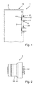
- FIG. 2 schematically a plug-in device 4 is shown, which can be inserted into an opening 20 of the housing 2.
- the plug-in device 4 has connection pins 44, which with the appropriate electronics module, which in FIG. 2 not shown, can be contacted electrically.
- a mechanical connection between the plug-in device and the electronic module 3 can be produced by attaching the electronic module 3 to the plug-in device 4.
- the connection pins 44 can be passed through complementary openings in the electronics module 3 and then soldered, glued or bonded to the electronics module. Accordingly, the electronic module 3 can be electrically contacted and mechanically held firmly on the plug-in device 4.
- the flange 40 can be seen, which can come into contact with the housing area around the opening 20 of the housing 2 around.
- An insertion portion 46 of the connector housing 42 connects to the flange 40 at.
- This lead-through section 46 is passed through the opening 20 in the housing 2 and then serves, in its guided through the opening 20 of the housing 2 extension, for contacting with a supplied from outside the housing 2 plug or a corresponding cable to the electrical connection.
- FIGS. 3 and 4 schematically shows how a plug-in device 4 can be brought into engagement with corresponding recesses 30 of the electronic module 3, and attached thereto, for example by soldering or gluing, and can be electrically contacted.
- FIG. 4 Accordingly, an electronic module 3 with three plug-in devices 4 attached thereto is shown.
- the plug-in devices 4 are attached to the electronic module 3 so firmly that the electronic module 3 can be held on the plug devices 4.
- FIG. 5 schematically shows how the electronic module 3 can be introduced with the respective plug devices 4 in a corresponding housing 2 with openings 20 provided therein.
- a sealed implementation of an electrical contacting of the electronic module 3 is made possible and, on the other hand, the electronics module 3 is held in the housing 2.
- FIG. 6 is shown in accordance with the assembled state of the housing 2 with the plug-in devices 4 mounted and welded therein.
- a flexible element can be provided for example via longer pins of the plug-in device 4 or by a short cable between the plug-in device 4 and the electronic module 3.
- the electronic module 3 is then still held on the plug-in device 4 to the housing 2 and in particular requires no further fasteners to be connected to the housing 2. The holding of the electronic module 3 then takes place via the flexible element on the plug-in device 4, so that mechanical stresses can be reduced.
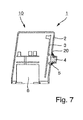
- FIG. 7 schematically shows a cross section through a device 1, in which in a housing 2 in a corresponding opening 20, a plug-in device 4 is welded via a weld 5.
- an electronic module 3 is attached in the form of a circuit board on the back, which faces the interior of the housing 2.
- an electromechanical actuator 6 is further added, which is controlled by the electronic module 3 and which can drive a filling valve so that the filling valve can be opened and closed.
- the housing 2 can accordingly be designed as a complete drive module 10, which comprises a self-contained drive module 10 with an electromechanical actuator 6 and an electronic module 3 that drives it.
- a gear unit which can then be coupled to the valve stem of the filling valve.
- the drive module 10 By providing the drive module 10 in this form, it is possible to safely and fluid-tightly accommodate a drive, which comprises both an electromechanical actuator 6 and the electronic module 3 assigned to the electromechanical actuator 6, in a housing 2.
- the drive module 10 may accordingly be provided as a whole decentrally on each individual filling member and be controlled easily via a central control.
- the corresponding implementation of the control lines or the electrical contact is effected via the fluid-tight arrangement of the plug-in device 4.
- the drive module 10 can be replaced as a whole in case of failure of a Greinsky senor, the contact can be carried out simply by connecting a correspondingly complementary connector via the plug device 4 and the drive module 10 with the filling member or the filling valve is mechanically connected. Accordingly, no troublesome troubleshooting must be performed, but the drive module 10 is easily replaced if there is a defect in the electronics or the electromechanical actuator. Accordingly complicated troubleshooting is not necessary and the replacement or maintenance can also be performed by less specialized operators.
Landscapes
- Engineering & Computer Science (AREA)
- Microelectronics & Electronic Packaging (AREA)
- Mechanical Engineering (AREA)
- Connector Housings Or Holding Contact Members (AREA)
- Basic Packing Technique (AREA)
- Electrically Driven Valve-Operating Means (AREA)
- Filling Of Jars Or Cans And Processes For Cleaning And Sealing Jars (AREA)
- Devices For Dispensing Beverages (AREA)
Abstract
Description
- Die vorliegende Erfindung betrifft eine Vorrichtung zum Befüllen eines Behälters mit einem Füllprodukt, bevorzugt in einer Getränkeabfüllanlage, in welcher ein Gehäuse zur Aufnahme eines Elektronikmoduls vorgesehen ist.
- Aus dem Stand der Technik sind Getränkeabfüllanlagen bekannt, bei welchen Füllorgane zur Befüllung der zu befüllenden Behälter mit einem Füllprodukt vorgesehen sind, welche mittels elektromechanischer Aktuatoren angesteuert werden. Die elektromechanischen Aktuatoren werden jeweils über Elektronikmodule mit den jeweiligen Steuerspannungen beziehungsweise Steuerströmen versorgt, derart, dass ein vorgegebener Öffnungs- und/oder Schließzustand des jeweiligen Füllventils des Füllorgans erreicht werden kann.
- Die Elektronikmodule, welche zur Ansteuerung der elektromechanischen Aktuatoren in den Füllorganen vorgesehen sind, sind üblicherweise in zentralen Schankschränken angeordnet, welche beispielsweise zusammen mit einem Füllerkarussell rotieren oder gegenüber einem rotierenden Füllerkarussell feststehend angeordnet sind. Um die jeweiligen Steuersignale beziehungsweise die Steuer- und/oder Schaltströme an die jeweiligen elektromechanischen Aktuatoren zu übertragen, sind Kabeldurchführungen durch die jeweiligen Wände der Schaltschränke vorgesehen.
- Dabei ist es bekannt, einen solchen Schaltschrank mit einem leichten Überdruck zu beaufschlagen, beispielsweise durch Druckluft, um sicherzustellen, dass keine Fluide wie Reinigungsflüssigkeiten, Füllprodukte oder Feuchtigkeit von außen in den Schaltschrank eindringen und die Elektronikmodule beschädigen können.
- Die bekannte Lösung eines zentralen Schaltschranks mit dem bekannten Aufbau ist bezüglich der Herstellung der jeweiligen elektrischen Verbindungen aufwändig, da zunächst die jeweiligen Kabel durch die Öffnungen in den zentralen Schaltschränken hindurchgeführt werden müssen und die Elektronikmodule kontaktiert werden müssen, und dann die Kabelführungen abgedichtet werden müssen. Weiterhin erhöht das ständige Beaufschlagen der zentralen Schaltschränke mit Druckluft die Betriebskoten der jeweiligen Getränkeabfüllanlage.
- Es ist daher eine Aufgabe der vorliegenden Erfindung, eine Vorrichtung zum Befüllen eines Behälters mit einem Füllprodukt anzugeben, welche einen verbesserten Aufbau bereitstellt.
- Diese Aufgabe wird durch eine Vorrichtung zum Befüllen eines Behälters mit einem Füllprodukt mit den Merkmalen des Anspruchs 1 gelöst. Vorteilhafte Weiterbildungen ergeben sich aus den Unteransprüchen.
- Entsprechend wird eine Vorrichtung zum Befüllen eines Behälters mit einem Füllprodukt in einer Getränkeabfüllanlage vorgeschlagen, umfassend ein Gehäuse zur Aufnahme eines Elektronikmoduls zur Steuerung eines elektromechanischen Aktuators eines Füllventils, ein in dem Gehäuse aufgenommenes Elektronikmodul sowie mindestens eine im Gehäuse vorgesehene Öffnung zur Durchführung einer elektrischen Kontaktierung des Elektronikmoduls von außerhalb des Gehäuses. Erfindungsgemäß ist die Öffnung durch eine mit dem Gehäuse verschweißte Steckvorrichtung zur Durchführung der elektrischen Kontaktierung fluiddicht verschlossen.
- Dadurch, dass die Öffnung in dem Gehäuse durch eine mit dem Gehäuse verschweißte Steckvorrichtung zur Durchführung der elektrischen Kontaktierung fluiddicht verschlossen ist, kann eine einfache Kontaktierung des Elektronikmoduls von außerhalb des Gehäuses erreicht werden. Durch das fluiddichte Verschweißen der Steckvorrichtung mit dem Gehäuse kann weiterhin eine absolut dichte Durchführung der elektrischen Kontaktierung erreicht werden. Wenn das Gehäuse und die Steckvorrichtung aus einem metallischen Material bestehen, kann auf diese Weise weiterhin eine Erdung des Gehäuses über den Stecker erreicht werden, so dass zusätzliche Maßnahmen zur Erdung des Gehäuses nicht notwendig sind. In einem weiteren Ausführungsbeispiel kann auch eine Erdung der Steckvorrichtung und des daran angebrachten Elektronikmoduls über das Gehäuse erreicht werden.
- Weiterhin ermöglicht es das Anschweißen der Steckvorrichtung in der Öffnung des Gehäuses, dass die Montage der Getränkeabfüllanlage sowie eine möglicherweise anfallende Wartung beziehungsweise ein Austausch des Gehäuses mit dem Elektronikmodul auf einfache Weise durchgeführt werden können, da die Durchführung von Kabeln durch die Gehäusewandung und das anschließende Kontaktieren des Elektronikmoduls sowie das Abdichten der Durchführung fortfällt. Vielmehr kann die jeweilige elektrische Kontaktierung des Elektronikmoduls von außen durch ein direktes Anschließen einer entsprechenden, zu der am Gehäuse festgeschweißten Steckvorrichtung kompatiblen Steckvorrichtung erreicht werden.
- Durch die fluiddichte Abdichtung, welche mittels des Verschweißens der Steckvorrichtung mit dem Gehäuse erreicht wird, kann weiterhin auf ein Beaufschlagen beziehungsweise Überströmen des Gehäuses mit Druckluft verzichtet werden, da eine dichte Abdichtung erreicht wird.
- Vorteilhaft weist die durch das Verschweißen erzeugte fluiddichte Abdichtung eine Schweißnaht auf, die durch ein Laserschweißverfahren erzeugt wurde, bevorzugt unter Verwendung eines gepulsten Lasers mit niedriger Leistung. Dadurch erfolgt ein möglichst geringer Wärmeeintrag in die Steckvorrichtung und eine entsprechende Beschädigung der Steckvorrichtung durch Hitze kann vermieden werden. Besonders bevorzugt wird die Schweißnaht im I-Stoß, also eine I-Naht erzeugt. Im Gegensatz zum Kehlstoß ist beim I-Stoß die Wärmeeinbringung und Wärmeableitung besser, da nicht so viel Material im Bereich der Naht angeordnet ist.
- Bevorzugt ist die Steckvorrichtung mit dem Elektronikmodul elektrisch verbunden, um eine Kontaktierung des Elektronikmoduls von außen zu ermöglichen.
- Besonders bevorzugt ist die Steckvorrichtung mechanisch mit dem Elektronikmodul verbunden und das Elektronikmodul ist über die Steckvorrichtung im Gehäuse gehalten. Damit kann durch die Verschweißung der Steckvorrichtung in der Öffnung des Gehäuses neben der vollständigen fluiddichten Abdichtung des Gehäuses gleichzeitig auch ein Halten des Elektronikmoduls am Gehäuse erreicht werden. Dadurch wird nicht nur eine sichere und fluiddichte Abdichtung des Gehäuses im Bereich der Durchführung der elektrischen Kontaktierung bereitgestellt, sondern gleichzeitig auch das Elektronikmodul sicher am Gehäuse befestigt und eine Erdung bereitgestellt. Auf weitere Befestigungsmittel zum Befestigen des Elektronikmoduls kann entsprechend verzichtet werden.
- Bevorzugt ist die Steckvorrichtung beziehungsweise ein Steckvorrichtungsgehäuse aus dem gleichen Material ausgebildet, wie das Gehäuse zur Aufnahme des Elektronikmoduls. Auf diese Weise kann ein problemloses und sicheres Verschweißen der Steckvorrichtung mit dem Gehäuse erreicht werden. Dabei können das Gehäuse sowie die Steckvorrichtung beispielsweise aus einem Metall, beispielsweise einem Edelstahl, oder einem Kunststoff ausgebildet sein. Weitere vorteilhafte und stoffschlüssig verbindbare Materialien zur Ausbildung eines Gehäuses zur Aufnahme eines Elektronikmoduls sind ebenfalls denkbar.
- Eine besonders zuverlässige Abdichtung wird erreicht, wenn die Steckvorrichtung selbst fluiddicht ausgebildet ist.
- Bevorzugt umfasst die Steckvorrichtung einen Flansch zur Anlage an einem die Öffnung umgebenden Bereich des Gehäuses, und auf der gegenüberliegenden Seite des Gehäuses ist eine Schweißnaht zur fluiddichten Abdichtung und mechanischen Aufnahme der Steckvorrichtung an dem Gehäuse vorgesehen. So lässt sich auf einfach herzustellende Weise eine mechanisch zuverlässige Verbindung herstellen.
- In einer weiteren bevorzugten Ausbildung der Vorrichtung ist ein Füllorgan vorgesehen, welches über einen elektromechanischen Aktuator betätigt wird. Das Gehäuse zur Aufnahme des Elektronikmoduls ist dabei direkt an dem Füllorgan beziehungsweise dem elektromechanischen Aktuator angeordnet. Entsprechend kann durch eine Anordnung eines Gehäuses mit einem entsprechenden Elektronikmodul an jedem Füllorgan einer Getränkeabfüllanlage eine dezentrale Anordnung der Elektronikmodule erreicht werden. Auf einen zentralen Schaltschrank kann entsprechend verzichtet werden beziehungsweise dieser kann kleiner ausgeführt werden. Weiterhin entfällt auf diese Weise auch die aufwändige Verkabelung von dem zentralen Schaltschrank zu den jeweiligen mechanischen Aktuatoren.
- Bevorzugt ist das Gehäuse zur Aufnahme des Elektronikmoduls derart als eigenständiges Modul ausgebildet, dass es als Modul mit einem elektromechanischen Aktuator verbunden werden kann, um die Betätigung eines Füllventils in einem Füllorgan zu ermöglichen. Das Gehäuse kann neben dem Elektronikmodul auch einen elektromechanischen Aktuator aufnehmen, so dass das Gehäuse mit dem elektromechanischen Aktuator sowie dem Elektronikmodul an einem Füllorgan, insbesondere einem Füllventil, angeordnet werden kann und entsprechend für eine Betätigung des Füllventils sorgt. Durch den modularen Aufbau wird es ermöglicht, das Gehäuse mit dem Elektronikmodul und eventuell dem elektromechanischen Aktuator als gesamtes Modul auszutauschen und entsprechend bei einem Defekt eines einzelnen Füllorgans durch den Austausch des so ausgebildeten Antriebsmoduls eine Wiederherstellung der Betriebsfähigkeit des Füllorgans auf einfache Weise zu erreichen.
- Entsprechend entfällt in einer solchen Ausbildung eine aufwändige Fehlersuche sowie ein aufwändiges Wiederverbinden von Elektronikbausteinen mit elektromechanischen Aktuatoren, so wie es in der herkömmlichen Anordnung mit einem zentralen Schaltschrank notwendig war. Vielmehr kann ein einfaches Anbinden des Antriebsmoduls durch einfaches Zusammenstecken der Steckvorrichtung erreicht werden.
- Um einen Ausgleich von mechanischen Spannungen, die beispielsweise durch die Wärmeausdehnung des Gehäuses beziehungsweise des Elektronikmoduls auftreten, zu reduzieren beziehungsweise diese zu kompensieren, ist bevorzugt zwischen der Steckvorrichtung und dem Elektronikmodul ein flexibles Element vorgesehen. Dieses kann beispielsweise dadurch erreicht werden, dass das Elektronikmodul über längere Pins mit der Steckvorrichtung verbunden ist oder eine Verbindung der Steckvorrichtung mit dem Elektronikmodul über ein vorzugsweise kurzes Kabel in dem Gehäuse vorgesehen ist. Das Elektronikmodul ist dann immer noch über die Steckvorrichtung an dem Gehäuse gehalten und benötigt insbesondere keine weiteren Befestigungselemente, um mit dem Gehäuse verbunden zu werden. Die Verbindung beziehungsweise das Halten des Elektronikmoduls findet dann über das flexible Element an der Steckvorrichtung statt, so dass die oben beschriebenen vorteilhaften Wirkungen weiterhin erreicht werden.
- Die oben beschriebene Aufgabe wird weiterhin durch ein Gehäuse zur Aufnahme eines Elektronikmoduls zur Steuerung eines elektromechanischen Aktuators eines Füllventils in einer Getränkeabfüllanlage mit den Merkmalen des Anspruchs 11 gelöst. Vorteilhafte Weiterbildungen ergeben sich aus dem Unteranspruch.
- Bevorzugte weitere Ausführungsformen und Aspekte der vorliegenden Erfindung werden durch die nachfolgende Beschreibung der Figuren näher erläutert. Dabei zeigen:
- Figur 1
- eine schematische Schnittdarstellung durch ein Gehäuse zur Aufnahme eines Elektronikmoduls in einem ersten Ausführungsbeispiel;
- Figur 2
- eine schematische seitliche Draufsicht auf eine Steckvorrichtung;
- Figur 3
- eine schematische perspektivische Darstellung eines Elektronikmoduls und an diesem anzubringenden Steckvorrichtungen;
- Figur 4
- das Elektronikmodul der
Figur 3 mit daran angebrachten Steckvorrichtungen; - Figur 5
- eine schematische perspektivische Darstellung des Vorgangs des Einsetzens des Elektronikmoduls in ein Gehäuse;
- Figur 6
- eine schematische perspektivische Darstellung des Gehäuses mit eingesetzten Steckvorrichtungen, an welchen das Elektronikmodul gehalten ist; und
- Figur 7
- eine schematische Schnittdarstellung durch ein ein Elektronikmodul sowie einen elektromechanischen Aktuator umschließendes Gehäuse.
- Im Folgenden werden bevorzugte Ausführungsbeispiele anhand der Figuren beschrieben. Dabei werden gleiche, ähnliche oder gleichwirkende Elemente in den unterschiedlichen Figuren mit identischen Bezugszeichen bezeichnet und auf eine wiederholte Beschreibung dieser Elemente wird in der nachfolgenden Beschreibung teilweise verzichtet, um Redundanzen zu vermeiden.
-
Figur 1 zeigt schematisch einen Teil einer Vorrichtung 1 zum Befüllen eines Behälters mit einem Füllprodukt in Form eines Antriebsmoduls 10 zum Antreiben eines nicht gezeigten Füllventils der Vorrichtung 1. - Die Vorrichtung 1 und insbesondere das Antriebsmodul 10 umfasst ein Gehäuse 2, in welchem ein Elektronikmodul 3 aufgenommen ist. Das Elektronikmodul 3 ist hier schematisch in Form einer Schaltplatine dargestellt. Bei dem Elektronikmodul 3 kann es sich beispielsweise um eine Motorsteuerung für einen elektromechanischen Aktuator handeln, welcher die zum Antrieb des Füllventils benötigten Hübe bereitstellt.
- Das Gehäuse 2 ist an sich fluiddicht ausgebildet, weist aber Öffnungen 20 auf, durch welche hindurch das Elektronikmodul 3 von der Außenseite des Gehäuses 2 aus kontaktiert werden kann.
- In jeder Öffnung 20 ist eine Steckvorrichtung 4, welche in dem gezeigten Ausführungsbeispiel als Steckerbuchse ausgebildet ist, aufgenommen. Die Steckvorrichtung 4 kann aber auch als Stecker ausgebildet sein - abhängig von dem jeweils in der Vorrichtung 1 verwendeten Anschlusskonzept. Dabei ist die Steckvorrichtung 4 so durch die Öffnung 20 hindurchgeführt, dass sie mit einem Flansch 40 an der inneren Oberfläche des Gehäuses 2 um die Öffnung 20 herum in Anlage kommt. Mit anderen Worten kann die Steckvorrichtung 4 nicht vollständig durch die Öffnung 20 hindurchgeschoben werden, sondern nur, bis der Flansch 40 am Gehäuse 2 anliegt. Der Flansch 40 hat entsprechend einen größeren Durchmesser als die Öffnung 20.
- Die Öffnung 20 und die Steckvorrichtung 4 beziehungsweise deren Steckvorrichtungsgehäuse 42 haben bevorzugt einen kreisrunden Querschnitt, so dass die Öffnung 20 als Bohrung ausgebildet sein kann.
- Die Steckvorrichtung 4 ist mit dem Gehäuse 2 fluiddicht verschweißt. Entsprechend ist eine Schweißnaht 5 zu erkennen, welche auf der Außenseite des Gehäuses 2 vorgesehen ist und welche sich um die Öffnung 20 und um die Steckvorrichtung 4 herum erstreckt. Damit ist die Steckvorrichtung 4 mechanisch sicher in der Öffnung 20 des Gehäuses 2 gehalten und ist gleichzeitig auch fluiddicht abgedichtet.
- Durch die Verschweißung ist die Steckvorrichtung 4 nicht nur fluiddicht und fest in der Öffnung 20 des Gehäuses 2 gehalten, sondern es besteht auch eine materialschlüssige Verbindung zwischen der Steckvorrichtung 4 und dem Gehäuse 2. Die Steckvorrichtung 4 kann sich entsprechend auch durch Vibrationen oder andere mechanische Einflüsse nicht mehr von dem Gehäuse 2 lösen und verschließt dieses fluiddicht. Die Steckvorrichtung 4 selbst ist dabei bereits fluiddicht ausgebildet und wirkt quasi als Stopfen für die Öffnung 20.
- Die Steckvorrichtung 4 und insbesondere das Steckvorrichtungsgehäuse 42 ist besonders bevorzugt aus dem gleichen Material ausgebildet, wie das Gehäuse 2. Hierbei kann das Steckvorrichtungsgehäuse 42 beispielsweise aus einem Metall, besonders bevorzugt einem Edelstahl, ausgebildet sein. Das Gehäuse 2 ist entsprechend aus dem gleichen Material ausgebildet. Entsprechend kann die Schweißnaht 5 eine zuverlässige materialschlüssige Verbindung zwischen der Steckvorrichtung 4 und dem Gehäuse 2 herstellen. Alternativ können Gehäuse 2 und Steckvorrichtung 4 auch aus einem Kunststoffmaterial ausgebildet sein.
- Alternativ und besonders bevorzugt weist die durch das Verschweißen erzeugte fluiddichte Abdichtung eine Schweißnaht auf, die durch ein Laserschweißverfahren erzeugt wurde, bevorzugt unter Verwendung eines gepulsten Lasers mit niedriger Leistung. Dadurch erfolgt ein möglichst geringer Wärmeeintrag in die Steckvorrichtung und eine entsprechende Beschädigung der Steckvorrichtung durch Hitze kann vermieden werden. Besonders bevorzugt wird die Schweißnaht im I-Stoß, also eine I-Naht erzeugt. Im Gegensatz zum Kehlstoß ist beim I-Stoß die Wärmeeinbringung und Wärmeableitung besser, da nicht so viel Material im Bereich der Naht angeordnet ist.
- Das Elektronikmodul 3 in Form der Platine ist über Anschlusspins 44 der Steckvorrichtung 4 elektrisch kontaktiert. Entsprechend kann ein von außerhalb des Gehäuses 2 in die Steckvorrichtung 4 eingeführter Steckkontakt über die Anschlusspins 44 elektrisch mit dem Elektronikmodul 3 kontaktiert werden. Da die Steckvorrichtung 4 aber fluiddicht abschließend in dem Gehäuse 2 aufgenommen ist und weiterhin die Steckvorrichtung 4 selbst auch fluiddicht ausgeführt ist, ist das Innere des Gehäuses 2 zuverlässig fluiddicht gegenüber der Außenseite abgeschirmt.
- Das Elektronikmodul 3 wird aber über die Anschlusspins 44 fest an der Steckvorrichtung 4 gehalten. Mit anderen Worten ist die Steckvorrichtung 4 mechanisch so fest mit dem Elektronikmodul 3 verbunden, dass bei der nachfolgenden Verschweißung der Steckvorrichtung 4 mit dem Gehäuse 2 auch das Elektronikmodul 3 mechanisch fest am Gehäuse 2 gehalten ist. Entsprechend ist das Elektronikmodul 3 über die Steckvorrichtung 4 fest mit dem Gehäuse 2 verbunden. Damit ist das Bereitstellen weiterer Befestigungselemente beziehungsweise Befestigungsmittel zum Halten des Elektronikmoduls 3 an dem Gehäuse 2 nicht notwendig und wird einzig über die Steckvorrichtung 4 am Gehäuse 2 gehalten.
- In
Figur 2 ist schematisch eine Steckvorrichtung 4 gezeigt, welche in eine Öffnung 20 des Gehäuses 2 eingesetzt werden kann. Die Steckvorrichtung 4 weist Anschlusspins 44 auf, welche mit dem entsprechenden Elektronikmodul, das inFigur 2 nicht gezeigt ist, elektrisch kontaktiert werden können. Neben der elektrischen Kontaktierung kann über ein Befestigen des Elektronikmoduls 3 an der Steckvorrichtung 4 auch eine mechanische Verbindung zwischen der Steckvorrichtung und dem Elektronikmodul 3 hergestellt werden. Beispielsweise können die Anschlusspins 44 durch zu ihnen komplementäre Öffnungen im Elektronikmodul 3 hindurchgeführt werden und dann mit dem Elektronikmodul verlötet, verklebt oder gebondet werden. Entsprechend kann das Elektronikmodul 3 elektrisch kontaktiert werden und mechanisch fest an der Steckvorrichtung 4 gehalten werden. - Weiterhin ist der Flansch 40 zu erkennen, welcher in Anlage mit dem Gehäusebereich um die Öffnung 20 des Gehäuses 2 herum kommen kann. Ein Durchführabschnitt 46 des Steckvorrichtungsgehäuses 42 schließt sich an den Flansch 40 an. Dieser Durchführabschnitt 46 wird durch die Öffnung 20 im Gehäuse 2 hindurchgeführt und dient dann, in seiner durch die Öffnung 20 des Gehäuses 2 hindurchgeführten Erstreckung, zur Kontaktierung mit einem von außerhalb des Gehäuses 2 zugeführten Steckers beziehungsweise eines entsprechenden Kabels zum elektrischen Anschluss.
- In den
Figuren 3 und 4 ist schematisch dargestellt, wie eine Steckvorrichtung 4 mit entsprechenden Ausnehmungen 30 des Elektronikmoduls 3 in Eingriff gebracht werden kann, und an diesen, beispielsweise durch Verlöten oder Verkleben, befestigt und elektrisch kontaktiert werden kann. - In
Figur 4 ist entsprechend ein Elektronikmodul 3 mit drei daran angebrachten Steckvorrichtungen 4 gezeigt. Die Steckvorrichtungen 4 sind an dem Elektronikmodul 3 so fest angebracht, dass das Elektronikmodul 3 über die Steckvorrichtungen 4 gehalten werden kann. - In
Figur 5 ist schematisch gezeigt, wie das Elektronikmodul 3 mit den jeweiligen Steckvorrichtungen 4 in ein entsprechendes Gehäuse 2 mit darin vorgesehenen Öffnungen 20 eingebracht werden kann. Damit wird zum einen eine abgedichtete Durchführung einer elektrischen Kontaktierung des Elektronikmoduls 3 ermöglicht und zum anderen das Elektronikmodul 3 im Gehäuse 2 gehalten. InFigur 6 ist entsprechend der montierte Zustand des Gehäuses 2 mit den darin angebrachten und verschweißten Steckvorrichtungen 4 gezeigt. - Um einen Ausgleich von mechanischen Spannungen, die beispielsweise durch die Wärmeausdehnung des Gehäuses 2 beziehungsweise des Elektronikmoduls 3 auftreten, zu reduzieren beziehungsweise diese zu kompensieren, ist bevorzugt zwischen der Steckvorrichtung 4 und dem Elektronikmodul 3 ein flexibles Element vorgesehen. Dieses flexible Element kann beispielsweise über längere Pins der Steckvorrichtung 4 oder durch ein kurzes Kabel zwischen der Steckvorrichtung 4 und dem Elektronikmodul 3 vorgesehen sein. Das Elektronikmodul 3 ist dann immer noch über die Steckvorrichtung 4 an dem Gehäuse 2 gehalten und benötigt insbesondere keine weiteren Befestigungselemente, um mit dem Gehäuse 2 verbunden zu werden. Das Halten des Elektronikmoduls 3 findet dann aber über das flexible Element an der Steckvorrichtung 4 statt, so dass mechanische Spannungen reduziert werden können.
-
Figur 7 zeigt schematisch einen Querschnitt durch eine Vorrichtung 1, in welcher in einem Gehäuse 2 in einer entsprechenden Öffnung 20 eine Steckvorrichtung 4 über eine Schweißnaht 5 verschweißt ist. An der Steckvorrichtung 4 ist auf deren Rückseite, welche dem Innenraum des Gehäuses 2 zugewendet ist, ein Elektronikmodul 3 in Form einer Platine befestigt. Damit ist sowohl die Durchführung für die elektrische Kontaktierung des Elektronikmoduls 3 bereitgestellt, als auch ein sicheres Halten des Elektronikmoduls 3 erreicht. - In dem Gehäuse 2 ist weiterhin ein elektromechanischer Aktuator 6 aufgenommen, welcher von dem Elektronikmodul 3 angesteuert wird und welcher ein Füllventil so antreiben kann, dass das Füllventil geöffnet und geschlossen werden kann.
- Das Gehäuse 2 kann entsprechend als vollständiges Antriebsmodul 10 ausgebildet sein, welches ein in sich abgeschlossenes Antriebsmodul 10 mit einem elektromechanischen Aktuator 6 und ein diesen ansteuerndes Elektronikmodul 3 umfasst. In dem Antriebsmodul 10 kann auch eine Getriebeeinheit vorgesehen sein, welche dann mit dem Ventilstößel des Füllventils gekoppelt werden kann.
- Durch die Bereitstellung des Antriebsmoduls 10 in dieser Form ist es möglich, einen Antrieb, welcher sowohl einen elektromechanischen Aktuator 6 als auch die dem elektromechanischen Aktuator 6 zugeordnete Elektronikmodul 3 umfasst, in einem Gehäuse 2 sicher und fluiddicht unterzubringen. Das Antriebsmodul 10 kann entsprechend als Ganzes dezentral an jedem einzelnen Füllorgan vorgesehen sein und einfach über eine zentrale Steuerung angesteuert werden. Die entsprechende Durchführung der Steuerleitungen beziehungsweise der elektrischen Kontaktierung wird dabei über die fluiddichte Anordnung der Steckvorrichtung 4 bewirkt.
- In einer Getränkeabfüllanlage kann entsprechend beim Ausfall eines Füllorganes aufgrund von Elektronikproblemen oder Antriebsproblemen das Antriebsmodul 10 als Ganzes ausgetauscht werden, wobei die Kontaktierung einfach dadurch durchgeführt werden kann, dass über die Steckvorrichtung 4 ein entsprechend dazu komplementärer Stecker angeschlossen wird und das Antriebsmodul 10 mit dem Füllorgan beziehungsweise dem Füllventil mechanisch verbunden wird. Entsprechend muss keine aufwändige Fehlersuche durchgeführt werden, sondern das Antriebsmodul 10 wird einfach ausgetauscht, wenn ein Defekt der Elektronik oder des elektromechanischen Aktuators vorliegt. Entsprechend sind komplizierte Fehlersuchen nicht notwendig und der Austausch beziehungsweise die Wartung kann auch von wenig spezialisiertem Bedienpersonal durchgeführt werden.
- Soweit anwendbar, können alle einzelnen Merkmale, die in den einzelnen Ausführungsbeispielen dargestellt sind, miteinander kombiniert und/oder ausgetauscht werden, ohne den Bereich der Erfindung zu verlassen.
-
- 1
- Vorrichtung zum Befüllen eines Behälters mit einem Füllprodukt
- 10
- Antriebsmodul
- 2
- Gehäuse
- 20
- Öffnung
- 3
- Elektronikmodul
- 30
- Ausnehmung<
- 4
- Steckvorrichtung
- 40
- Flansch
- 42
- Steckvorrichtungsgehäuse
- 44
- Anschlusspin
- 46
- Durchführungsabschnitt
- 5
- Schweißnaht
- 6
- elektromechanischer Aktuator
Claims (12)
- Vorrichtung (1) zum Befüllen eines Behälters mit einem Füllprodukt in einer Getränkeabfüllanlage, umfassend ein Gehäuse (2) zur Aufnahme eines Elektronikmoduls (3) zur Steuerung eines elektromechanischen Aktuators (6) eines Füllventils, ein in dem Gehäuse (2) aufgenommenes Elektronikmodul (3) sowie mindestens eine im Gehäuse (2) vorgesehene Öffnung (20) zur Durchführung einer elektrischen Kontaktierung des Elektronikmoduls (3) von außerhalb des Gehäuses (2),
dadurch gekennzeichnet, dass
die Öffnung (20) durch eine mit dem Gehäuse (2) verschweißte Steckvorrichtung (4) zur Durchführung der elektrischen Kontaktierung fluiddicht verschlossen ist. - Vorrichtung (1) gemäß Anspruch 1, dadurch gekennzeichnet, dass die Steckvorrichtung (4) mit dem Elektronikmodul (3) elektrisch verbunden ist.
- Vorrichtung (1) gemäß Anspruch 1 oder 2, dadurch gekennzeichnet, dass die Steckvorrichtung (4) mechanisch mit dem Elektronikmodul (3) verbunden ist und das Elektronikmodul (3) über die Steckvorrichtung (4) im Gehäuse (2) gehalten ist.
- Vorrichtung (1) gemäß einem der vorstehenden Ansprüche, dadurch gekennzeichnet, dass das Material der Steckvorrichtung (4), insbesondere eines Steckvorrichtungsgehäuses (42), dem Material des Gehäuses (2) entspricht, wobei das Material bevorzugt ein Metall, besonders bevorzugt ein Edelstahl, oder ein Kunststoff ist.
- Vorrichtung (1) gemäß einem der vorstehenden Ansprüche, dadurch gekennzeichnet, dass die Steckvorrichtung (4) fluiddicht ausgebildet ist.
- Vorrichtung (1) gemäß einem der vorstehenden Ansprüche, dadurch gekennzeichnet, dass die Steckvorrichtung (4) einen Flansch (40) zur Anlage an einem die Öffnung (20) umgebenden Bereich des Gehäuses (2) umfasst, und auf der gegenüberliegenden Seite des Gehäuses (2) eine Schweißnaht (5) zur fluiddichten Abdichtung und mechanischen Aufnahme der Steckvorrichtung (4) an dem Gehäuse (2) vorgesehen ist.
- Vorrichtung (1) gemäß einem der vorstehenden Ansprüche, dadurch gekennzeichnet, das in dem Gehäuse (2) ein elektromechanischer Aktuator (6) aufgenommen ist, welcher über das Elektronikmodul (3) angesteuert wird.
- Vorrichtung (1) gemäß einem der vorstehenden Ansprüche, dadurch gekennzeichnet, dass das Gehäuse (2) ein Antriebsmodul (10) ausbildet, welches mit einem Füllventil austauschbar in Verbindung bringbar ist.
- Vorrichtung (1) gemäß einem der vorstehenden Ansprüche, dadurch gekennzeichnet, dass mindestens zwei Füllorgane vorgesehen sind, welche jeweils mit einem Antriebsmodul (10) versehen sind.
- Vorrichtung (1) gemäß einem der vorstehenden Ansprüche, dadurch gekennzeichnet, dass die Steckvorrichtung (4) über ein flexibles Element an dem Elektronikmodul (3) angebunden ist.
- Gehäuse (2) zur Aufnahme eines Elektronikmoduls (3) zur Steuerung eines elektromechanischen Aktuators (6) eines Füllventils in einer Getränkeabfüllanlage, umfassend ein in dem Gehäuse (2) aufgenommenes Elektronikmodul (3) sowie mindestens eine im Gehäuse (2) vorgesehene Öffnung (20) zur Durchführung einer elektrischen Kontaktierung des Elektronikmoduls (3) von außerhalb des Gehäuses (2),
dadurch gekennzeichnet, dass
die Öffnung (20) durch eine mit dem Gehäuse (2) verschweißte Steckvorrichtung (4) zur Durchführung der elektrischen Kontaktierung fluiddicht verschlossen ist. - Gehäuse (2) gemäß Anspruch 11, gekennzeichnet durch die Merkmale eines der Ansprüche 2 bis 10.
Priority Applications (1)
| Application Number | Priority Date | Filing Date | Title |
|---|---|---|---|
| SI201530422T SI3006392T1 (sl) | 2014-10-09 | 2015-10-09 | Naprava za polnjenje vsebnika s polnilnim izdelkom |
Applications Claiming Priority (1)
| Application Number | Priority Date | Filing Date | Title |
|---|---|---|---|
| DE102014114641.7A DE102014114641A1 (de) | 2014-10-09 | 2014-10-09 | Vorrichtung zum Befüllen eines Behälters mit einem Füllprodukt |
Publications (3)
| Publication Number | Publication Date |
|---|---|
| EP3006392A2 true EP3006392A2 (de) | 2016-04-13 |
| EP3006392A3 EP3006392A3 (de) | 2016-04-20 |
| EP3006392B1 EP3006392B1 (de) | 2018-09-26 |
Family
ID=54325338
Family Applications (1)
| Application Number | Title | Priority Date | Filing Date |
|---|---|---|---|
| EP15189073.8A Active EP3006392B1 (de) | 2014-10-09 | 2015-10-09 | Vorrichtung zum befüllen eines behälters mit einem füllprodukt |
Country Status (6)
| Country | Link |
|---|---|
| US (1) | US9862587B2 (de) |
| EP (1) | EP3006392B1 (de) |
| JP (1) | JP6678421B2 (de) |
| CN (1) | CN105501484B (de) |
| DE (1) | DE102014114641A1 (de) |
| SI (1) | SI3006392T1 (de) |
Cited By (1)
| Publication number | Priority date | Publication date | Assignee | Title |
|---|---|---|---|---|
| WO2018060419A1 (de) * | 2016-09-29 | 2018-04-05 | Krones Ag | Vorrichtung zum beeinflussen des volumenstroms eines füllprodukts in einer abfüllanlage |
Families Citing this family (3)
| Publication number | Priority date | Publication date | Assignee | Title |
|---|---|---|---|---|
| DE102016105725A1 (de) * | 2016-03-30 | 2017-10-05 | Molex Connectivity GmbH | Gedichtete elektrische Steckverbinderanordnung |
| DE102020202774A1 (de) | 2020-03-04 | 2021-09-09 | Atlas Elektronik Gmbh | Gehäuse zur Aufnahme einer Signalverarbeitungsplatine zur Verarbeitung von elektrischen Signalen unter Wasser |
| DE102021122566A1 (de) * | 2021-08-31 | 2023-03-02 | Endress+Hauser SE+Co. KG | Feldgerät der Automatisierungstechnik |
Family Cites Families (20)
| Publication number | Priority date | Publication date | Assignee | Title |
|---|---|---|---|---|
| AU434565B2 (en) * | 1967-05-19 | 1973-03-13 | Ross Connolly Keith | Apparatus for filling containers with carbonated beverages |
| JP2003090749A (ja) * | 2001-09-20 | 2003-03-28 | Mitsubishi Heavy Ind Ltd | 電磁流量計 |
| JP4929659B2 (ja) | 2005-09-26 | 2012-05-09 | 株式会社ジェイテクト | 電子制御装置 |
| DE102006046488B4 (de) * | 2006-09-29 | 2012-06-28 | Sauer-Danfoss Gmbh & Co. Ohg | Abgedichteter elektrischer Anschluss eines Gehäuses einer elektrischen Steuereinheit und Hydraulikmaschine mit einem Gehäuse mit einem derartigen Anschluss |
| DE102006056258A1 (de) * | 2006-11-27 | 2008-05-29 | Hilmar Kraus | Baugruppe aus elektrischen und/oder elektronischen Bauteilen |
| JP4153549B1 (ja) | 2007-06-28 | 2008-09-24 | タイコエレクトロニクスアンプ株式会社 | 防水型コネクタ、防水型コネクタの実装構造、および防水型コネクタの実装方法 |
| DE102007035872A1 (de) * | 2007-07-31 | 2009-02-05 | Krones Ag | Vorrichtung für Behälter |
| DE202008006413U1 (de) * | 2008-05-09 | 2009-09-24 | Sensor-Technik Wiedemann Gmbh | Gehäuse bzw. Steckverbindung |
| IT1392525B1 (it) * | 2009-01-08 | 2012-03-09 | Electrolux Home Prod Corp | Procedimento per erogare un liquido in un contenitore e relativo erogatore |
| DE102009016322A1 (de) * | 2009-04-06 | 2010-10-07 | Khs Ag | Füllsystem |
| DE102009032795A1 (de) * | 2009-07-10 | 2011-01-13 | Krones Ag | Einfülleinrichtung zum Befüllen von Behältnissen |
| DE102009038062B4 (de) * | 2009-08-19 | 2011-12-22 | Harting Electric Gmbh & Co. Kg | Verbindungsbauteil mit mindestens zwei nach außen wirkenden Kupplungselementen sowie Verfahren zur Herstellung eines solchen Verbindungsbauteiles |
| JP2012090481A (ja) * | 2010-10-21 | 2012-05-10 | Sumitomo Electric Ind Ltd | 防水ケース及び車載電子機器 |
| JP2012198106A (ja) * | 2011-03-22 | 2012-10-18 | Panasonic Corp | 超音波センサ |
| DE102011006195A1 (de) * | 2011-03-28 | 2012-10-04 | Robert Bosch Gmbh | Modulare elektrische Steckverbinderanordnung |
| JP2012231004A (ja) * | 2011-04-26 | 2012-11-22 | Honda Elesys Co Ltd | 導通端子半田ストレス防止構造 |
| JP2013243251A (ja) * | 2012-05-21 | 2013-12-05 | Sinfonia Technology Co Ltd | 電子モジュール及び電子モジュールの製造方法 |
| EP2728985B1 (de) * | 2012-11-02 | 2018-01-31 | Siemens Schweiz AG | Stellantrieb mit elektrischer Steckverbindung |
| CN203399453U (zh) * | 2013-08-15 | 2014-01-15 | 闫海亮 | 防水电器壳 |
| TWM496259U (zh) * | 2014-09-26 | 2015-02-21 | Jess Link Products Co Ltd | 防水電連接器模組及其防水外殼 |
-
2014
- 2014-10-09 DE DE102014114641.7A patent/DE102014114641A1/de not_active Withdrawn
-
2015
- 2015-10-08 JP JP2015200255A patent/JP6678421B2/ja active Active
- 2015-10-09 CN CN201510648378.7A patent/CN105501484B/zh active Active
- 2015-10-09 US US14/880,002 patent/US9862587B2/en active Active
- 2015-10-09 EP EP15189073.8A patent/EP3006392B1/de active Active
- 2015-10-09 SI SI201530422T patent/SI3006392T1/sl unknown
Non-Patent Citations (1)
| Title |
|---|
| None |
Cited By (2)
| Publication number | Priority date | Publication date | Assignee | Title |
|---|---|---|---|---|
| WO2018060419A1 (de) * | 2016-09-29 | 2018-04-05 | Krones Ag | Vorrichtung zum beeinflussen des volumenstroms eines füllprodukts in einer abfüllanlage |
| US11208311B2 (en) | 2016-09-29 | 2021-12-28 | Krones Ag | Device for influencing the volume flow of a filling product in a filling system |
Also Published As
| Publication number | Publication date |
|---|---|
| EP3006392B1 (de) | 2018-09-26 |
| US20160101971A1 (en) | 2016-04-14 |
| CN105501484B (zh) | 2018-03-13 |
| US9862587B2 (en) | 2018-01-09 |
| EP3006392A3 (de) | 2016-04-20 |
| CN105501484A (zh) | 2016-04-20 |
| SI3006392T1 (sl) | 2018-12-31 |
| JP6678421B2 (ja) | 2020-04-08 |
| JP2016103469A (ja) | 2016-06-02 |
| DE102014114641A1 (de) | 2016-04-14 |
Similar Documents
| Publication | Publication Date | Title |
|---|---|---|
| EP3006392B1 (de) | Vorrichtung zum befüllen eines behälters mit einem füllprodukt | |
| DE4004834C2 (de) | Ventilbaugruppe | |
| DE102008033904B4 (de) | Antriebsendblock für eine Magnetronanordnung mit einem rotierenden Target | |
| EP2690314B1 (de) | Spindelantrieb | |
| DE102005001314A1 (de) | Vorrichtung zum Öffnen und/oder Schließen einer Tür | |
| EP3982007A1 (de) | Kompakter elektrischer linearantrieb für eine zahnstange, insbesondere eines hydraulikventils, und verfahren zu seiner montage | |
| DE102011008394B4 (de) | Stufenschalter | |
| DE112010002997T5 (de) | Universeller lastschalter | |
| EP1846656B1 (de) | Elektrische trennung in kraftstoffinjektoren | |
| EP1921242A1 (de) | Betätigungsvorrichtung für bewegliche Gebäudeteile, insbesondere schwenkbare Fenster oder Klappen | |
| EP2159891A2 (de) | Elektroinstallationsdose | |
| WO2018197145A1 (de) | Anschlusseinrichtung | |
| EP1868182A1 (de) | Ultraschallgeber mit Kühlflüssigkeit, Ultraschall-Schweissanordnung und Verfahren zum Betreiben eines Ultraschallgebers | |
| EP2777373A2 (de) | Frequenzumrichter und federelement hierfür | |
| DE102016124070A1 (de) | Scharniersystem für ein elektrisches Haushaltsgerät | |
| EP0073423B1 (de) | Verbindungselement für vollfeststoffisolierte Stromleiter | |
| EP2933416B1 (de) | Türantrieb | |
| DE102015106369B4 (de) | Kapselfüllmaschine | |
| DE102019215547B3 (de) | Modular aufgebautes Lenkungssteuergerät mit einem von außen zugänglichen Modulaufnahmebereich zur Aufnahme eines Hardwaremoduls | |
| DE2744502A1 (de) | Mittelspannungsschalter | |
| EP2466604A1 (de) | Antriebseinheit zum Betreiben eines Schalters einer Mittel- oder Hochspannungsschaltanlage | |
| DE102019103569B4 (de) | Leiterrahmen für eine Batterievorrichtung eines Elektrofahrzeugs | |
| DE19827481A1 (de) | Manuelle Fernsteuerungsvorrichtung, insbesondere Fluidverteiler | |
| WO2004092604A1 (de) | Umlenkhebel | |
| DE102009042644A1 (de) | Gasisolierte Hochspannungsschaltanlage |
Legal Events
| Date | Code | Title | Description |
|---|---|---|---|
| PUAL | Search report despatched |
Free format text: ORIGINAL CODE: 0009013 |
|
| PUAI | Public reference made under article 153(3) epc to a published international application that has entered the european phase |
Free format text: ORIGINAL CODE: 0009012 |
|
| AK | Designated contracting states |
Kind code of ref document: A2 Designated state(s): AL AT BE BG CH CY CZ DE DK EE ES FI FR GB GR HR HU IE IS IT LI LT LU LV MC MK MT NL NO PL PT RO RS SE SI SK SM TR |
|
| AX | Request for extension of the european patent |
Extension state: BA ME |
|
| AK | Designated contracting states |
Kind code of ref document: A3 Designated state(s): AL AT BE BG CH CY CZ DE DK EE ES FI FR GB GR HR HU IE IS IT LI LT LU LV MC MK MT NL NO PL PT RO RS SE SI SK SM TR |
|
| AX | Request for extension of the european patent |
Extension state: BA ME |
|
| RIC1 | Information provided on ipc code assigned before grant |
Ipc: H05K 5/06 20060101ALI20160311BHEP Ipc: B67C 3/00 20060101AFI20160311BHEP Ipc: H05K 5/02 20060101ALI20160311BHEP Ipc: B65B 3/00 20060101ALI20160311BHEP |
|
| 17P | Request for examination filed |
Effective date: 20161020 |
|
| RBV | Designated contracting states (corrected) |
Designated state(s): AL AT BE BG CH CY CZ DE DK EE ES FI FR GB GR HR HU IE IS IT LI LT LU LV MC MK MT NL NO PL PT RO RS SE SI SK SM TR |
|
| 17Q | First examination report despatched |
Effective date: 20170214 |
|
| GRAP | Despatch of communication of intention to grant a patent |
Free format text: ORIGINAL CODE: EPIDOSNIGR1 |
|
| INTG | Intention to grant announced |
Effective date: 20180419 |
|
| GRAS | Grant fee paid |
Free format text: ORIGINAL CODE: EPIDOSNIGR3 |
|
| GRAA | (expected) grant |
Free format text: ORIGINAL CODE: 0009210 |
|
| AK | Designated contracting states |
Kind code of ref document: B1 Designated state(s): AL AT BE BG CH CY CZ DE DK EE ES FI FR GB GR HR HU IE IS IT LI LT LU LV MC MK MT NL NO PL PT RO RS SE SI SK SM TR |
|
| REG | Reference to a national code |
Ref country code: GB Ref legal event code: FG4D Free format text: NOT ENGLISH |
|
| REG | Reference to a national code |
Ref country code: CH Ref legal event code: EP Ref country code: FR Ref legal event code: PLFP Year of fee payment: 4 |
|
| REG | Reference to a national code |
Ref country code: AT Ref legal event code: REF Ref document number: 1045769 Country of ref document: AT Kind code of ref document: T Effective date: 20181015 |
|
| REG | Reference to a national code |
Ref country code: IE Ref legal event code: FG4D Free format text: LANGUAGE OF EP DOCUMENT: GERMAN |
|
| REG | Reference to a national code |
Ref country code: DE Ref legal event code: R096 Ref document number: 502015006054 Country of ref document: DE |
|
| REG | Reference to a national code |
Ref country code: NL Ref legal event code: MP Effective date: 20180926 |
|
| PG25 | Lapsed in a contracting state [announced via postgrant information from national office to epo] |
Ref country code: SE Free format text: LAPSE BECAUSE OF FAILURE TO SUBMIT A TRANSLATION OF THE DESCRIPTION OR TO PAY THE FEE WITHIN THE PRESCRIBED TIME-LIMIT Effective date: 20180926 Ref country code: RS Free format text: LAPSE BECAUSE OF FAILURE TO SUBMIT A TRANSLATION OF THE DESCRIPTION OR TO PAY THE FEE WITHIN THE PRESCRIBED TIME-LIMIT Effective date: 20180926 Ref country code: LT Free format text: LAPSE BECAUSE OF FAILURE TO SUBMIT A TRANSLATION OF THE DESCRIPTION OR TO PAY THE FEE WITHIN THE PRESCRIBED TIME-LIMIT Effective date: 20180926 Ref country code: BG Free format text: LAPSE BECAUSE OF FAILURE TO SUBMIT A TRANSLATION OF THE DESCRIPTION OR TO PAY THE FEE WITHIN THE PRESCRIBED TIME-LIMIT Effective date: 20181226 Ref country code: FI Free format text: LAPSE BECAUSE OF FAILURE TO SUBMIT A TRANSLATION OF THE DESCRIPTION OR TO PAY THE FEE WITHIN THE PRESCRIBED TIME-LIMIT Effective date: 20180926 Ref country code: GR Free format text: LAPSE BECAUSE OF FAILURE TO SUBMIT A TRANSLATION OF THE DESCRIPTION OR TO PAY THE FEE WITHIN THE PRESCRIBED TIME-LIMIT Effective date: 20181227 Ref country code: NO Free format text: LAPSE BECAUSE OF FAILURE TO SUBMIT A TRANSLATION OF THE DESCRIPTION OR TO PAY THE FEE WITHIN THE PRESCRIBED TIME-LIMIT Effective date: 20181226 |
|
| REG | Reference to a national code |
Ref country code: LT Ref legal event code: MG4D |
|
| PG25 | Lapsed in a contracting state [announced via postgrant information from national office to epo] |
Ref country code: LV Free format text: LAPSE BECAUSE OF FAILURE TO SUBMIT A TRANSLATION OF THE DESCRIPTION OR TO PAY THE FEE WITHIN THE PRESCRIBED TIME-LIMIT Effective date: 20180926 Ref country code: HR Free format text: LAPSE BECAUSE OF FAILURE TO SUBMIT A TRANSLATION OF THE DESCRIPTION OR TO PAY THE FEE WITHIN THE PRESCRIBED TIME-LIMIT Effective date: 20180926 Ref country code: AL Free format text: LAPSE BECAUSE OF FAILURE TO SUBMIT A TRANSLATION OF THE DESCRIPTION OR TO PAY THE FEE WITHIN THE PRESCRIBED TIME-LIMIT Effective date: 20180926 |
|
| PG25 | Lapsed in a contracting state [announced via postgrant information from national office to epo] |
Ref country code: IS Free format text: LAPSE BECAUSE OF FAILURE TO SUBMIT A TRANSLATION OF THE DESCRIPTION OR TO PAY THE FEE WITHIN THE PRESCRIBED TIME-LIMIT Effective date: 20190126 Ref country code: NL Free format text: LAPSE BECAUSE OF FAILURE TO SUBMIT A TRANSLATION OF THE DESCRIPTION OR TO PAY THE FEE WITHIN THE PRESCRIBED TIME-LIMIT Effective date: 20180926 Ref country code: ES Free format text: LAPSE BECAUSE OF FAILURE TO SUBMIT A TRANSLATION OF THE DESCRIPTION OR TO PAY THE FEE WITHIN THE PRESCRIBED TIME-LIMIT Effective date: 20180926 Ref country code: EE Free format text: LAPSE BECAUSE OF FAILURE TO SUBMIT A TRANSLATION OF THE DESCRIPTION OR TO PAY THE FEE WITHIN THE PRESCRIBED TIME-LIMIT Effective date: 20180926 Ref country code: RO Free format text: LAPSE BECAUSE OF FAILURE TO SUBMIT A TRANSLATION OF THE DESCRIPTION OR TO PAY THE FEE WITHIN THE PRESCRIBED TIME-LIMIT Effective date: 20180926 Ref country code: CZ Free format text: LAPSE BECAUSE OF FAILURE TO SUBMIT A TRANSLATION OF THE DESCRIPTION OR TO PAY THE FEE WITHIN THE PRESCRIBED TIME-LIMIT Effective date: 20180926 Ref country code: PL Free format text: LAPSE BECAUSE OF FAILURE TO SUBMIT A TRANSLATION OF THE DESCRIPTION OR TO PAY THE FEE WITHIN THE PRESCRIBED TIME-LIMIT Effective date: 20180926 |
|
| PG25 | Lapsed in a contracting state [announced via postgrant information from national office to epo] |
Ref country code: SM Free format text: LAPSE BECAUSE OF FAILURE TO SUBMIT A TRANSLATION OF THE DESCRIPTION OR TO PAY THE FEE WITHIN THE PRESCRIBED TIME-LIMIT Effective date: 20180926 Ref country code: SK Free format text: LAPSE BECAUSE OF FAILURE TO SUBMIT A TRANSLATION OF THE DESCRIPTION OR TO PAY THE FEE WITHIN THE PRESCRIBED TIME-LIMIT Effective date: 20180926 Ref country code: PT Free format text: LAPSE BECAUSE OF FAILURE TO SUBMIT A TRANSLATION OF THE DESCRIPTION OR TO PAY THE FEE WITHIN THE PRESCRIBED TIME-LIMIT Effective date: 20190126 |
|
| REG | Reference to a national code |
Ref country code: CH Ref legal event code: PL |
|
| REG | Reference to a national code |
Ref country code: BE Ref legal event code: MM Effective date: 20181031 |
|
| REG | Reference to a national code |
Ref country code: DE Ref legal event code: R097 Ref document number: 502015006054 Country of ref document: DE |
|
| PG25 | Lapsed in a contracting state [announced via postgrant information from national office to epo] |
Ref country code: LU Free format text: LAPSE BECAUSE OF NON-PAYMENT OF DUE FEES Effective date: 20181009 |
|
| REG | Reference to a national code |
Ref country code: IE Ref legal event code: MM4A |
|
| PG25 | Lapsed in a contracting state [announced via postgrant information from national office to epo] |
Ref country code: DK Free format text: LAPSE BECAUSE OF FAILURE TO SUBMIT A TRANSLATION OF THE DESCRIPTION OR TO PAY THE FEE WITHIN THE PRESCRIBED TIME-LIMIT Effective date: 20180926 Ref country code: MC Free format text: LAPSE BECAUSE OF FAILURE TO SUBMIT A TRANSLATION OF THE DESCRIPTION OR TO PAY THE FEE WITHIN THE PRESCRIBED TIME-LIMIT Effective date: 20180926 |
|
| PLBE | No opposition filed within time limit |
Free format text: ORIGINAL CODE: 0009261 |
|
| STAA | Information on the status of an ep patent application or granted ep patent |
Free format text: STATUS: NO OPPOSITION FILED WITHIN TIME LIMIT |
|
| PG25 | Lapsed in a contracting state [announced via postgrant information from national office to epo] |
Ref country code: CH Free format text: LAPSE BECAUSE OF NON-PAYMENT OF DUE FEES Effective date: 20181031 Ref country code: BE Free format text: LAPSE BECAUSE OF NON-PAYMENT OF DUE FEES Effective date: 20181031 Ref country code: LI Free format text: LAPSE BECAUSE OF NON-PAYMENT OF DUE FEES Effective date: 20181031 |
|
| 26N | No opposition filed |
Effective date: 20190627 |
|
| PG25 | Lapsed in a contracting state [announced via postgrant information from national office to epo] |
Ref country code: IE Free format text: LAPSE BECAUSE OF NON-PAYMENT OF DUE FEES Effective date: 20181009 |
|
| PG25 | Lapsed in a contracting state [announced via postgrant information from national office to epo] |
Ref country code: MT Free format text: LAPSE BECAUSE OF FAILURE TO SUBMIT A TRANSLATION OF THE DESCRIPTION OR TO PAY THE FEE WITHIN THE PRESCRIBED TIME-LIMIT Effective date: 20180926 |
|
| PG25 | Lapsed in a contracting state [announced via postgrant information from national office to epo] |
Ref country code: TR Free format text: LAPSE BECAUSE OF FAILURE TO SUBMIT A TRANSLATION OF THE DESCRIPTION OR TO PAY THE FEE WITHIN THE PRESCRIBED TIME-LIMIT Effective date: 20180926 |
|
| PG25 | Lapsed in a contracting state [announced via postgrant information from national office to epo] |
Ref country code: HU Free format text: LAPSE BECAUSE OF FAILURE TO SUBMIT A TRANSLATION OF THE DESCRIPTION OR TO PAY THE FEE WITHIN THE PRESCRIBED TIME-LIMIT; INVALID AB INITIO Effective date: 20151009 Ref country code: MK Free format text: LAPSE BECAUSE OF NON-PAYMENT OF DUE FEES Effective date: 20180926 Ref country code: CY Free format text: LAPSE BECAUSE OF FAILURE TO SUBMIT A TRANSLATION OF THE DESCRIPTION OR TO PAY THE FEE WITHIN THE PRESCRIBED TIME-LIMIT Effective date: 20180926 |
|
| GBPC | Gb: european patent ceased through non-payment of renewal fee |
Effective date: 20191009 |
|
| PG25 | Lapsed in a contracting state [announced via postgrant information from national office to epo] |
Ref country code: GB Free format text: LAPSE BECAUSE OF NON-PAYMENT OF DUE FEES Effective date: 20191009 |
|
| REG | Reference to a national code |
Ref country code: AT Ref legal event code: MM01 Ref document number: 1045769 Country of ref document: AT Kind code of ref document: T Effective date: 20201009 |
|
| PG25 | Lapsed in a contracting state [announced via postgrant information from national office to epo] |
Ref country code: AT Free format text: LAPSE BECAUSE OF NON-PAYMENT OF DUE FEES Effective date: 20201009 |
|
| P01 | Opt-out of the competence of the unified patent court (upc) registered |
Effective date: 20230523 |
|
| PGFP | Annual fee paid to national office [announced via postgrant information from national office to epo] |
Ref country code: IT Payment date: 20230913 Year of fee payment: 9 |
|
| PGFP | Annual fee paid to national office [announced via postgrant information from national office to epo] |
Ref country code: FR Payment date: 20230911 Year of fee payment: 9 |
|
| PGFP | Annual fee paid to national office [announced via postgrant information from national office to epo] |
Ref country code: SI Payment date: 20230913 Year of fee payment: 9 Ref country code: DE Payment date: 20230830 Year of fee payment: 9 |