EP3519344B1 - Flèche télescopique dotée d'un système de haubanage pour une grue mobile et procédé de haubanage correspondant - Google Patents
Flèche télescopique dotée d'un système de haubanage pour une grue mobile et procédé de haubanage correspondant Download PDFInfo
- Publication number
- EP3519344B1 EP3519344B1 EP18700763.8A EP18700763A EP3519344B1 EP 3519344 B1 EP3519344 B1 EP 3519344B1 EP 18700763 A EP18700763 A EP 18700763A EP 3519344 B1 EP3519344 B1 EP 3519344B1
- Authority
- EP
- European Patent Office
- Prior art keywords
- jib
- telescoping
- guying
- tension rods
- telescopic
- Prior art date
- Legal status (The legal status is an assumption and is not a legal conclusion. Google has not performed a legal analysis and makes no representation as to the accuracy of the status listed.)
- Active
Links
- 238000000034 method Methods 0.000 title claims description 6
- 230000007246 mechanism Effects 0.000 claims description 25
- 230000000284 resting effect Effects 0.000 claims description 3
- 210000002414 leg Anatomy 0.000 description 21
- 210000000689 upper leg Anatomy 0.000 description 4
- 235000004443 Ricinus communis Nutrition 0.000 description 1
- 240000000528 Ricinus communis Species 0.000 description 1
- 238000004873 anchoring Methods 0.000 description 1
- 238000005452 bending Methods 0.000 description 1
- 230000000295 complement effect Effects 0.000 description 1
- 238000010276 construction Methods 0.000 description 1
- 238000005096 rolling process Methods 0.000 description 1
- 230000007704 transition Effects 0.000 description 1
Images


Classifications
-
- B—PERFORMING OPERATIONS; TRANSPORTING
- B66—HOISTING; LIFTING; HAULING
- B66C—CRANES; LOAD-ENGAGING ELEMENTS OR DEVICES FOR CRANES, CAPSTANS, WINCHES, OR TACKLES
- B66C23/00—Cranes comprising essentially a beam, boom, or triangular structure acting as a cantilever and mounted for translatory of swinging movements in vertical or horizontal planes or a combination of such movements, e.g. jib-cranes, derricks, tower cranes
- B66C23/62—Constructional features or details
- B66C23/64—Jibs
- B66C23/70—Jibs constructed of sections adapted to be assembled to form jibs or various lengths
- B66C23/701—Jibs constructed of sections adapted to be assembled to form jibs or various lengths telescopic
- B66C23/706—Jibs constructed of sections adapted to be assembled to form jibs or various lengths telescopic telescoped by other means
-
- B—PERFORMING OPERATIONS; TRANSPORTING
- B66—HOISTING; LIFTING; HAULING
- B66C—CRANES; LOAD-ENGAGING ELEMENTS OR DEVICES FOR CRANES, CAPSTANS, WINCHES, OR TACKLES
- B66C23/00—Cranes comprising essentially a beam, boom, or triangular structure acting as a cantilever and mounted for translatory of swinging movements in vertical or horizontal planes or a combination of such movements, e.g. jib-cranes, derricks, tower cranes
- B66C23/62—Constructional features or details
- B66C23/82—Luffing gear
- B66C23/821—Bracing equipment for booms
- B66C23/826—Bracing equipment acting at an inclined angle to vertical and horizontal directions
-
- B—PERFORMING OPERATIONS; TRANSPORTING
- B66—HOISTING; LIFTING; HAULING
- B66C—CRANES; LOAD-ENGAGING ELEMENTS OR DEVICES FOR CRANES, CAPSTANS, WINCHES, OR TACKLES
- B66C2700/00—Cranes
- B66C2700/03—Cranes with arms or jibs; Multiple cranes
- B66C2700/0321—Travelling cranes
- B66C2700/0357—Cranes on road or off-road vehicles, on trailers or towed vehicles; Cranes on wheels or crane-trucks
- B66C2700/0364—Cranes on road or off-road vehicles, on trailers or towed vehicles; Cranes on wheels or crane-trucks with a slewing arm
- B66C2700/0371—Cranes on road or off-road vehicles, on trailers or towed vehicles; Cranes on wheels or crane-trucks with a slewing arm on a turntable
Definitions
- the invention relates to a telescopic boom of a mobile crane with a plurality of telescopic sections telescopic from a jib basic box from a transport position into an operating position and with a guy system for bracing the telescopic boom, which comprises a plurality of tie rods connected to one another in succession, starting from the jib basic box via at least one guy support to at least one of the extended telescopic boom run.
- the invention also relates to a method for bracing a telescopic boom of a mobile crane, in which a plurality of clamping rods connected in succession are braced between a basic boom of a telescopic boom and at least one adjacent telescopic section of the telescopic boom.
- the two traction means also extend along the crane boom and are each guided over one of the two guy supports in the area of their free ends.
- deflection rollers are arranged on the guy supports, which are wrapped around at least once by the respective rope.
- Each pulley can be fixed using a holding function.
- the traction devices are wound up or unwound via the cable winches when the crane boom is extended and retracted and tensioned after the extension has been completed. After tensioning, the deflection rollers are also fixed. The tension of the traction means relieves the load on the crane boom and reduces or prevents bending of the crane boom.
- the German patent also discloses DE 34 47 095 C2 another telescopic boom on a superstructure of a crane.
- the telescopic boom is braced by an arrangement of tension cables and deflection pulleys.
- the tensioning cables are attached to each foot end of the respective telescopic sections, are deflected at each head end of the respective adjacent and outer telescopic sections via one of the deflection rollers and converge on a tensioning cylinder attached to the superstructure.
- the German patent DE 100 62 517 C2 relates to a guy system for a telescopic boom of a mobile crane.
- the telescopic boom has in the usual way a basic box on which a guy stand is arranged at right angles.
- a rear guying leads from a free end of the guy stand to the foot area of the basic box.
- a front guying is connected to the free end of the guy stand and to the head piece or to a collar of one of the inner boxes of the telescopic boom.
- the front guying is formed over its length by a number of interconnectable tension elements, each with a fixed length, in order to set the desired tensile force.
- the fixed lengths of the tension elements are dimensioned such that a certain number of tension elements corresponds to a predetermined discrete extension length of the telescopic boom.
- the patent US 4,982,853 discloses a guy system for a multi-stage Telescopic boom, wherein a guy support is attached to the base of the base box and further guy supports are each attached to the collar of the base box or to the collar of an inner box. There are tension cables between the guy supports, the tension cable being attached to the tension support and to the head of the telescopic boom.
- the Chinese utility model CN 202 558 505 U describes a guy system for a telescopic boom, where three guy ropes are guided from a head of the telescopic boom via a front guy support and a rear guy support with a rope deflection roller to a foot of the basic box.
- the invention has for its object to provide a telescopic boom for a mobile crane with a rod guy system and a guy method for this, which are characterized by a lighter design and improved handling in road operation and an increase in load capacity with unchanged telescopic boom dimensions.
- a telescopic boom of a mobile crane with a plurality of telescopic sections telescopic from a jib basic box from a transport position into an operating position and with a guy system for guying the telescopic boom, which comprises a plurality of clamping rods connected to one another in succession, starting from the jib main box via at least one guy support to at least one of the extend telescopic boom, an increase in the load and a lighter design achieved that a guide holder for the sliding tension rods is arranged on the boom base box, which receives the sliding tension rods in the transport position of the telescopic boom and in the operating position at least one of the sliding tension rods on one the guy supports are articulated at the outer end of the telescopic head and at the opposite end to an adjacent one Guy support one adjacent telescopic shot head can be fixed to a holding mechanism.
- the entire guy system is carried on the mobile crane, especially on the jib base box.
- the displaceable tension rods can advantageously be extended from the assigned guide holder or retracted into the latter.
- each guy support is arranged at the outer end of a boom head box head or a telescopic shot head.
- a guy support is arranged on the boom base box and on each telescopic section.
- the telescopic boom can therefore be braced at several points, which in turn increases the stability of the bracing and improves the load capacity of the telescopic boom. This also allows a lighter and smaller design to be implemented with the same load.
- the guying system is simplified in terms of design in that each guying support has an opening for the displaceable tensioning rods to be carried out and the holding mechanism for the respective displaceable tensioning rod is arranged in the region of the opening.
- the holding mechanism comprises a movable locking element with which the respective tension rod can be fixed in the opening in the operating position by engaging in a recess in the respective tension rod.
- each guy support comprises two legs, which are arranged on the right and left of the telescopic boom as seen in the longitudinal direction of the telescopic boom and an angle of 45 ° to 135 °, more preferably, is preferred Include 90 ° way.
- At least one tension rod is articulated and / or firmly attached to each leg of each guy support can be fixed on the holding mechanism.
- a guide mechanism which connects the guiding brackets of the guy system to the jib base box via a guy support, allows the guiding brackets to be set up from a transport position to an operating position and the guiding brackets and those resting on them in the operating position slidable tie rods run parallel to a longitudinal direction and above the telescopic boom.
- the guide holders can be pivoted from the transport position into the operating position via articulation points, the pivot points are arranged in the course of the guide holders and adjacent to the guy support, the displaceable tension rods in the transport position have the guide brackets aligned with the articulation points of the guide brackets.
- a guy is provided on the left and right stationary tension rods on the boom base box in the region of its foot.
- a simplified and space-saving method for bracing a telescopic boom in which a plurality of clamping rods connected in succession are braced between a boom base box of a telescopic boom and at least one adjacent telescopic section of the telescopic boom, is achieved in that, together with a successive extension of the individual telescopic sections from the boom basic box, one each the tension rods are extended from a guide holder from a transport position into an operating position and each tension rod is fixed in the operating position on a guy support of the adjacent telescopic section by means of a holding mechanism.
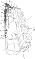
- FIG. 1 a perspective view of a mobile crane designated by 1 is shown.
- the mobile crane 1 essentially comprises an undercarriage 2 and an uppercarriage 3.
- the undercarriage 2 carries counterweights 4 and has four vehicle axles 5, each with two wheels 6 suitable for road use.
- the undercarriage 2 can of course also be equipped with more or less than four vehicle axles 5.
- the undercarriage 2 carries the superstructure 3, which can be pivoted about an essentially vertically oriented axis of rotation D with respect to the undercarriage 2.
- the superstructure 3 and the undercarriage 2 can of course also be rigidly mounted on one another.
- a combined driving and crane cabin 7 is arranged on the superstructure 3 and can be pivoted about a vertical axis K from the front - as seen in the forward direction F of the mobile crane 1 - to the rear and vice versa.
- the combined driving and crane cabin 7 is thus in the driving position behind the superstructure 3 and in the crane operating position on the side next to the superstructure 3.
- a luffing telescopic boom 8 is mounted on the superstructure, which is fully retracted for driving on the road and counter to the forward direction F of the Mobile crane 1 is placed on the undercarriage 2 at a shallow angle starting from a horizontal downward so that guy supports 15 arranged on the telescopic boom 8 and projecting upward do not increase the overall height when the mobile crane 1 is traveling. It is of course also possible to design the driving and crane cab 7 separately from one another.
- the telescopic boom 8 consists in the usual manner of a boom base box 9 and a plurality of extendable and retractable telescopic sections 10a-h and has a guy system 11 in order to achieve an increase in the load with the telescope boom 8 otherwise unchanged. With this guy system telescopic boom 8 with smaller diameters or cross sections can be realized while maintaining the load.
- the guy system 11 essentially consists of a large number of tension rods 16, 16 ', 16a-16h, 16a'-16h', of which the displaceable tension rods 16a-h, 16a'-h 'parallel to and with the telescopic sections 10a-10h. and extendable.
- the boom basic box 9 is connected in the usual manner at its foot to the superstructure 3 via a horizontal luffing axis W and via a luffing cylinder 12 (see Figure 2 ) can be swung up and down.
- the boom base box 9 takes in the telescopic sections 10a-h, which are arranged one inside the other and can be extended and retracted. In each extended state, the telescopic sections 10a-h are connected to one another via bolts, not shown.
- the foot of the respective inner and thus smaller telescopic section 10a-h is bolted to the next outer and larger telescopic section 10a-h or the boom basic box 9 via a suitable bolting position hole.
- the base of the telescopic section 10h is connected to the head 10 of the telescopic section 10g via the bolts (not shown).
- FIG 2 4 is a partial perspective view of the mobile crane 1 according to FIG Figure 1 shown with partially extended telescopic boom 8.
- the innermost and therefore uppermost telescopic section 10h is extended, the remaining telescopic sections 10a-g are still retracted.
- the superstructure 3 is for the crane operation from the position for road travel (see here Figure 1 ) pivoted through 180 °, so that the telescopic boom 8 points in the forward direction F and there is space for the arrangement of counterweights 4 on the rear of the superstructure 3.
- the driving and Crane cabin 7 has now been moved to the side of the superstructure 3 for crane operation.
- a lifting mechanism 14 with a cable drum for lifting and lowering the crane loads is arranged on the boom basic box 9.
- the cable drum of the lifting mechanism 14 points upwards and its rolling axis is arranged at right angles to the longitudinal direction L of the telescopic boom 8 (see also Figure 3 ).
- a lifting cable 18 is wound up and unwound from the lifting mechanism 14 and runs from the lifting mechanism 14 along and above the telescopic boom 8 to the end of the last telescopic section 10h.
- At the end of the last telescopic shot 10h there is a deflection roller 19 and a guide roller 31 (see Figure 3 ), over which the hoisting rope 18 is guided.
- the guy system 11 essentially comprises V- and fork-shaped guy supports 15, each of which is seen at the outer end of a head 9a of the boom base box 9, as seen in the longitudinal direction L of the telescopic boom 8 or a head 10 of each telescopic section 10a-h are arranged.
- Each V- and fork-shaped guy support 15 comprises a left leg 15a and a right leg 15a '.
- Each of the left and right legs 15, 15a ' consists of a lower part 15b, 15b' and an upper part 15c, 15c '.
- the two lower parts 15b, 15b ' when the telescopic boom 8 is horizontally oriented, connect each other on the outside and above in the area of corners of the telescopic sections 10a-h, which are essentially square in cross section, or of the basic boom box 9, which is essentially square in cross section, and extend obliquely below approximately an angle of 45 ° upwards and outwards.
- the upper parts 15c, 15c' adjoin one another at an angle of approximately 45 ° so that they extend vertically upwards.
- the telescopic boom 8 is braced by means of the fixed jib base frame tie rods 16, 16 'on the jib base frame 9 and the displaceable tie rods 16a-h, 16a'-h each in connection with the guy supports 15.
- the left and right stationary tie rods 16, 16' run in a transport position at a flat angle to the longitudinal direction L of the telescopic boom 8 and are each fixed at one end to the associated guy support 15 in the transition region between its lower and upper legs 15b, 15b ', 15c, 15c' and connected to the other end in the lateral region of the foot of the boom base box 9.
- the clamping forces acting on the first guy support 15 of the basic boom box 9 are thus introduced into the basic boom box 9 via the fixed clamping rods 16, 16.
- the displaceable tension rods 16a-h, 16a'-h ' are placed on the left and right guide holders 13a, 13b in the retracted state.
- Each of these guide holders 13a, 13b is designed as an upwardly open, flat U-shaped profile with U-shaped guide tracks for each of the displaceable tension rods 16a-h, 16a'-h 'and serves as a magazine for the displaceable tension rods 16a-h, 16a' -h 'when the telescopic boom 8 is retracted.
- the guide holders 13a, 13b are each pivoted at the head about an articulation point H, H' with a horizontal axis at the upper end of the legs 15a, 15a 'of the guy support 15 at the head of the boom base box 9a.
- the guide brackets 13a, 13b are mounted with a set-up mechanism 30 at the foot of the boom base box 9.
- the guide holders 13a, 13b with the displaceable tension rods 16a-h, 16a'-h ' are pivoted up from their transport position into an operating position by means of the toggle-type setting mechanism 30 via an auxiliary cylinder. In this operating position, the displaceable tension rods 16a-h, 16a'-h 'and the guide holders 13a, 13b run parallel and above the telescopic boom 8.
- hinge points H, H 'of all displaceable tension rods 16a-h, 16a'-h' and also the guide holder 13a, 13b lie in the transport position of the guide holder 13a, 13b and the telescopic boom 8 on a common, imaginary, horizontal axis.
- displaceable tension rods 16h, 16h ' With respect to an extended pair of the first or uppermost displaceable tension rods 16h, 16h 'is from the Figure 2nd It can be seen that the displaceable tension rods 16h, 16h 'have an articulation point H, H' in the vicinity of the uppermost guy support 15.
- the distance of the articulation point H, H 'to the fixed connection of the displaceable tension rods 16h, 16h' to the uppermost guy support 15 corresponds to the distance of the top guy support 15 to the articulation point H, H 'of the guide brackets 13a, 13b in the transport position of the telescopic boom 8.
- Corresponding pivot points H, H 'and associated distances can also be found in all other displaceable tension rods 16h, 16h', although these are not shown in the drawing.
- FIG 3 a perspective top view is shown diagonally from above of a fully extended telescopic boom 8.
- the guy supports 15 are arranged on each telescopic shot head 10 and on the boom basic box head 9a and are thus spaced apart from one another.
- the legs 15a and 15a 'of the guy support 15 are arranged on the right and left of the telescopic boom 8.
- the opposite upper parts 15c, 15c 'of the guy supports 15 are at a distance b from one another.
- the displaceable tension rods 16h, 16h ' the associated articulation points H, H "are shown in the vicinity of the uppermost guy support 15.
- Each of the displaceable tension rods 16a-h, 16a'-h' is thus formed in two parts.
- the lower parts 15b, 15b ' have a first length l and the upper parts 15c, 15c' have a second length l '. Since the displaceable tension rods 16a-h, 16a'-h 'are arranged in the operating position essentially in alignment with one another along the telescopic boom 8, the first and second lengths l, l' are to be adapted accordingly, since the diameter of the telescopic sections 10 ah is based on this Remove boom base box 9 and thus this is compensated for by an associated increase in lengths l, l '.
- FIG 4 shows a detailed view of a guy support 15 on a boom base box 9 of the telescopic boom 8. Since none in the present case displaceable tension rods 16a-h, 16a'-h 'are stored in the guide holder 13a, 13b, all telescopic sections 10a-10h are at least partially extended. It can also be seen that an opening angle ⁇ of the two legs 15a and 15a 'is approximately 45 ° to 135 °, preferably 90 °.
- the two legs 15a, 15a ' lie in a common, imaginary plane which is oriented at right angles to a longitudinal direction L of the telescopic boom 8.
- the lower parts 15b, 15b 'of the two legs 15a, 15a' themselves have an elongated triangle-like shape with the respectively adjoining vertical upper part 15c, 15c ', one base side of the triangle resting on the telescopic section 10a-h or on the boom base box 9 .
- an actuatable holding mechanism 17 is arranged in each case for fixing the displaceable tension rods 16a-h, 16a'-h '.
- the displaceable tension rods 16a-h, 16a'-h ' are each fixedly arranged on the associated upper part 15c, 15c' of a guy support 15.
- An articulation point H, H ' enables pivoting of the displaceable tension rods 16a-h, 16a'-h' inserted in the guide holders 13a, 13b into the transport position.
- the displaceable tension rods 16a-h, 16a'-h ' are fixed via the respective holding mechanism 17 at the upper ends of the upper parts 15c, 15c' of the legs 15a, 15a '.
- Each of the holding mechanisms 17 essentially consists of a left or right locking element 24a, 24b, which engages with a left or right recess 23a-c, 23a'-c 'in the displaceable tensioning rods 16a-h, 16a', which is designed to complement this in a form-fitting manner.
- -h ' can be brought (see also Figures 3 and 5 ).
- each displaceable tension rod 16a-h, 16a'-h ', three recesses 23a-c, 23a'-c' are arranged in the longitudinal direction at a distance and in succession: a first recess 23a, 23a 'at the beginning of the displaceable tension rods 16a-h , 16a'-h 'for fixing in the retracted state of the respective telescopic section 10a-h, a second recess 23b, 23b' in the middle of the displaceable tension rods 16a-h, 16a'-h 'for fixing in the case of a respective half-extended telescopic section 10a-h and a third recess 23c, 23c 'at the end of the displaceable tension rods 16a-h, 16a'-h' for fixing to a respective fully extended telescopic section 10a-h.
- the Figure 5 shows a detailed view of seven of the eight guy supports 15 when the telescopic sections 10a-g are retracted.
- the displaceable tension rods 16a-g, 16a'-g ' are also retracted and are received by the guide holder 13a, 13b.
- the displaceable tensioning rods 16a-h, 16a'-h ' run on rollers 27a-g, 27a'-g' which are arranged in and next to the upper legs 15c, 15c 'of the legs 15a, 15a' .
- the upper part 15c, 15c 'of the legs 15a, 15a' is each provided with an opening 32a-g, 32a'-g 'in which the displaceable tensioning rods 16a-h, 16a'-h' during their inward and outward movement be performed.
- These openings 32a-g, 32a'-g ' are delimited at the bottom by the rollers 27a-g, 27a'-g' and at the top by the locking elements 24a, 24b.
- a lateral boundary is provided by walls of the upper parts 15c, 15c '.
- the holding mechanism 17 for fixing the displaceable tension rods 16a-h, 16a'-h 'in the opening 32a-g, 32a'-g' to the desired extension length is shown.
- the respective locking element 24a, 24b can be moved in a sliding direction s 'and thus in the longitudinal direction of the respective upper part 15c, 15c' from a lower locking position into an upper unlocking position. In the locking position, the locking element 24a, 24b engages with the respective recess 23a, 23a 'of the respective displaceable tension rod 16a-h, 16a'-h'.
- the locking element 24a, 24b In the unlocked position, the locking element 24a, 24b is shifted upwards in the sliding direction s 'so that the locking element 24a, 24b has moved out of the respective recess 23a, 23a' and thus moves above the respective displaceable tensioning rod 16a-h, 16a'- h 'is located.
- the locking elements 24a, 24b are each prestressed in the locking position via an upper spring element 28a ', which acts downwards in the sliding direction s', so that a drive is required for moving in the unlocking position.
- This drive for moving the locking elements 24a, 24b is designed as follows.
- Each of the locking elements 24a, 24b is laterally connected to a left or right upper sliding element 25a ', 25b', which extends downward to the beginning of the upper part 15c, 15c '.
- the left and right wedge pieces 22a, 22b are attached to upper ends of the right and left lower slide members 25a, 25b, respectively.
- sliding elements 25a, 25b have a sliding roller 26a, 26b at the lower end, are displaceable in the longitudinal direction of the lower parts 15b, 15b 'in a sliding direction s and end at the lower end of the lower parts 15b, 15b' and are thus the surface of the respective one Telescopic shot 10a-h facing.
- the lower sliding elements 25a, 25b are each prestressed in the direction of the lower end of the lower parts 15b, 15b via a lower spring element 28a, 28b and thus in the locking position of the locking elements 24a, 24b.
- a drive with left and right sliding cylinders 29a, 29b is provided.
- a sliding wedge 21a, 21b (see also here Figure 4 ) attached, on which a ramp-like lower end is provided.
- the sliding wedges 21a, 21b are displaced below the left and right sliding rollers 26a, 26b by extending the sliding cylinders 29a, 29b in order to raise the lower sliding element 25a, 25b, on which the sliding rollers 26a, 26b act, in the sliding direction S.
- the sliding cylinders 29a, 29b are arranged on the right and left in the area of the upper corners of the boom base box 9 and can be moved in and out in a sliding direction S.
- the innermost telescopic section 10h of the telescopic boom 8 is extended together with its guy support 15. Since the displaceable tensioning rods 16h, 16h 'in the rod fixed points 20h, 20h' of the legs 15a and 15a 'of the guy support 15 are fastened to the guy support 15, they are simultaneously taken along in the longitudinal direction L of the telescopic boom 8 and thus pulled out of the guide holders 13a and 13b .
- the displaceable tensioning rods 16h, 16h ' are guided through the openings 32g, 32g' and on the rollers 27a, 27a 'of the guy supports 15 of the telescope section 10g which is not yet extended in the longitudinal direction L.
- the displaceable tension rods 16h, 16h ' are fixed on the legs 15a and 15a' by the two holding mechanisms 17 of the adjacent telescopic section 10g in the usual manner at half and full extension length.
- each telescopic section 10a-h which then define a telescopic section 10a-h in a full or half or otherwise pre-selected extension path of the telescopic section 10a-h.
- the displaceable tension rods 16a-g, 16a-g ' are then successively and sectionally clamped between the respective guy supports 15 of the telescopic sections 10a-f and the boom base box 9 in the same way.
Landscapes
- Engineering & Computer Science (AREA)
- Mechanical Engineering (AREA)
- Jib Cranes (AREA)
Claims (12)
- Bras télescopique (8) d'une grue mobile (1), ledit bras comprenant une pluralité de tronçons télescopiques (10a-h) pouvant se déployer de manière télescopique depuis un caisson de base de bras (9) d'une position de transport jusque dans une position de fonctionnement et un système de haubanage (11) destiné à haubaner le bras télescopique (8), lequel système comporte une pluralité de barres de haubanage (16a-h, 16a'-h') qui sont reliées successivement entre elles et qui s'étendent depuis le caisson de base de bras (9) jusqu'à l'un au moins des bras télescopiques déployés (8) par le biais d'au moins un support de haubanage (15),
caractérisé en ce que
un support de guidage (13a, 13b) destiné aux barres de haubanage (16a-h, 16a'-h') est disposé au niveau du caisson de base de bras (9) et reçoit les barres de haubanage (16a-h, 16a'-h') dans la position de transport du bras télescopique (8) reçoit et, dans la position de fonctionnement, l'une au moins des barres de haubanage (16a-h, 16a'-h') est articulée fermement sur l'un des supports de haubanage (15) à chaque fois à l'extrémité extérieure de la tête de tronçon télescopique (10) et, à l'extrémité opposée, peut être fixée à un mécanisme de retenue (17) sur un support de haubanage adjacent (15) d'une tête de tronçon télescopique adjacente (10). - Bras télescopique (8) selon la revendication 1, caractérisé en ce que chaque support de haubanage (15) est disposé à l'extrémité extérieure d'une tête de caisson de base de bras (9a) ou d'une tête de tronçon télescopique (10).
- Bras télescopique (8) selon la revendication 1 ou 2, caractérisé en ce qu'un support de haubanage (15) est disposé sur chaque caisson de base de bras (9) et à chaque tronçon télescopique (10a-h).
- Bras télescopique (8) selon l'une des revendications 1 à 3, caractérisé en ce que chaque support de haubanage (15) comporte une ouverture (32a-g, 32a'-g') par laquelle doivent passer les barres de haubanage coulissantes (16a-h, 16a'-h') et le mécanisme de retenue (17) destiné à la barre de haubanage coulissante respective (16a-h, 16a'-h') est disposée dans la région de l'ouverture (32a-g, 32a'-g').
- Bras télescopique (8) selon la revendication 4, caractérisé en ce que le mécanisme de retenue (17) comprend un élément de verrouillage mobile (24a, 24b) qui permet d'immobiliser la barre de haubanage coulissante respective (16a-h, 16a'-h') dans l'ouverture (32a-g, 32a'-g') dans la position de fonctionnement par engagement dans un évidement (23a-c, 23a'-c') ménagé la barre de haubanage coulissante respective (16a-h, 16a'-h').
- Bras télescopique (8) selon l'une des revendications 1 à 5, caractérisé en ce que chaque support de haubanage (15) comprend deux branches (15a, 15a') qui sont disposés à droite et à gauche du bras télescopique (8) depuis le centre de la bras télescopique (8) par référence à la direction longitudinale (L) du bras télescopique (8) et forment un angle (a) de 45° à 135°, de préférence de 90°.
- Bras télescopique (8) selon la revendication 6, caractérisé en ce qu'au moins une barre de haubanage coulissante (16a-h, 16a'-h') est solidement articulée à chaque branche (15a, 15a') de chaque support de haubanage (15) et/ou peut être immobilisée au niveau du mécanisme de retenue (17).
- Bras télescopique (8) selon les revendications 1 à 7, caractérisé en ce que les tronçons télescopiques successifs (10a-h) et le caisson de base de bras (9) peuvent être immobilisés l'un à l'autre.
- Bras télescopique (8) selon l'une des revendications 1 à 8, caractérisé en ce que le support de guidage (13a, 13b) peut être réglé d'une position de transport jusque dans une position de fonctionnement par un mécanisme de montage (30), qui relie le support de guidage (13a, 13b) du système de haubanage (11) au caisson de base de bras (9) par le biais d'un support de haubanage (15) et, dans la position de fonctionnement, le support de guidage (13a, 13b) et les barres de haubanage coulissantes (16a-h, 16a'-h') s'étendent parallèlement à une direction longitudinale ( L) et au-dessus du bras télescopique (8).
- Bras télescopique (8) selon la revendication 9, caractérisé en ce que les supports de guidage (13a, 13b) peuvent pivoter de la position de transport à la position de fonctionnement par le biais de points d'articulation (H, H'), les points d'articulation (H, H') sont disposés le long du support de guidage (13a, 13b) et de manière adjacente au support de haubanage, les barres de haubanage coulissantes (16a-h, 16a'-h') comportent, dans la position de transport sur les supports de guidage (13a, 13b), des points d'articulation (H, FT) alignés avec les points d'articulation (H, H') des supports de guidage (13a, 13b). 13b).
- Bras télescopique (8) selon l'une des revendications 1 à 10, caractérisé en ce que le support de haubanage (15) est haubané sur la tête (9a) du caisson de base de bras (9) par le biais de barres de haubanage fixes gauche et droite (16, 16') sur le caisson de base de bras (9) dans la région du pied de celui-ci.
- Procédé de haubanage d'un bras télescopique (8) d'une grue mobile (1), en particulier selon l'une des revendications 1 à 11, procédé dans lequel une pluralité de barres de haubanage coulissantes (16a-h, 16a'-h') reliées successivement entre elles sont haubanées entre un caisson de base de bras (9) d'un bras télescopique (8) et au moins un tronçon télescopique adjacent (10a-h) du bras télescopique (8), caractérisé en ce que l'une des barres de haubanage (16a-h, 16a'-h') est déployée d'un support de guidage (13a, 13b) d'une position de transport à une position de fonctionnement, conjointement avec un déploiement successif des tronçons télescopiques individuels (10a-h) depuis le caisson de base de bras (9), et chaque barre de haubanage coulissante (16a-h, 16a'-h') est immobilisée dans la position de fonctionnement sur un support de haubanage (15) du tronçon télescopique adjacent (10a-h) par le biais d'un mécanisme de retenue (17).
Applications Claiming Priority (2)
| Application Number | Priority Date | Filing Date | Title |
|---|---|---|---|
| DE102017101113.7A DE102017101113B3 (de) | 2017-01-20 | 2017-01-20 | Teleskopausleger mit Stangenabspannsystem für einen Mobilkran und Abspannverfahren hierfür |
| PCT/EP2018/051105 WO2018134249A1 (fr) | 2017-01-20 | 2018-01-17 | Flèche télescopique dotée d'un système de haubanage pour une grue mobile et procédé de haubanage correspondant |
Publications (2)
| Publication Number | Publication Date |
|---|---|
| EP3519344A1 EP3519344A1 (fr) | 2019-08-07 |
| EP3519344B1 true EP3519344B1 (fr) | 2020-04-01 |
Family
ID=61005832
Family Applications (1)
| Application Number | Title | Priority Date | Filing Date |
|---|---|---|---|
| EP18700763.8A Active EP3519344B1 (fr) | 2017-01-20 | 2018-01-17 | Flèche télescopique dotée d'un système de haubanage pour une grue mobile et procédé de haubanage correspondant |
Country Status (5)
| Country | Link |
|---|---|
| US (1) | US11130659B2 (fr) |
| EP (1) | EP3519344B1 (fr) |
| AU (1) | AU2018209160A1 (fr) |
| DE (1) | DE102017101113B3 (fr) |
| WO (1) | WO2018134249A1 (fr) |
Families Citing this family (7)
| Publication number | Priority date | Publication date | Assignee | Title |
|---|---|---|---|---|
| DE102016114837A1 (de) | 2016-08-10 | 2018-02-15 | Terex Global Gmbh | Teleskopausleger mit Abspannsystem für einen Mobilkran und Abspannverfahren hierfür |
| DE102019120134B3 (de) * | 2019-07-25 | 2020-09-10 | Tadano Demag Gmbh | Fahrzeugkran und Fahrzeugkransystem sowie Verfahren zum Aufrüsten und Abrüsten eines Fahrzeugkrans mit einer Abspannvorrichtung |
| DE102020129454B4 (de) | 2020-11-09 | 2023-08-17 | Tadano Demag Gmbh | Fahrzeugkran mit einem Auslegersystem |
| DE102020129762B3 (de) | 2020-11-11 | 2022-02-17 | Tadano Demag Gmbh | Teleskopausleger eines Mobilkrans |
| JP2022084003A (ja) * | 2020-11-25 | 2022-06-06 | タダノ デマグ ゲーエムベーハー | 基本伸縮ジブおよび追加伸縮ジブを有する移動式クレーンの伸縮ジブシステム、および対応する方法 |
| DE102020134714B4 (de) | 2020-12-22 | 2023-09-28 | Tadano Demag Gmbh | Fahrzeugkran mit einem wippbaren Hauptausleger und mit einem Zusatzauslegersystem |
| DE102022102318A1 (de) | 2022-02-01 | 2023-08-03 | Liebherr-Werk Ehingen Gmbh | Mobilkran mit abgespanntem Teleskopausleger |
Family Cites Families (27)
| Publication number | Priority date | Publication date | Assignee | Title |
|---|---|---|---|---|
| US2449703A (en) | 1948-09-21 | Snatch block | ||
| US1325053A (en) | 1919-12-16 | Telescoping tower | ||
| US3830376A (en) * | 1973-02-16 | 1974-08-20 | Harnischfeger Corp | Telescopic jib and bearing means therefor |
| US4004695A (en) * | 1975-04-16 | 1977-01-25 | Fulton Industries, Inc. | Channel and plate telescopic crane boom |
| DE2917829A1 (de) | 1979-05-03 | 1980-11-13 | Gottwald Kg Leo | Fahrzeugkran mit teleskopausleger |
| DE3447095C2 (de) | 1984-12-22 | 1995-04-06 | Krupp Ag Hoesch Krupp | Teleskopausleger für Krane |
| US4982853A (en) | 1989-02-09 | 1991-01-08 | Hikoma Seisakusho Co., Ltd. | Reinforcement mechanism for multi-stage telescopic boom |
| DE10022658B4 (de) | 1999-06-28 | 2007-10-04 | Terex-Demag Gmbh & Co. Kg | Teleskopkran |
| DE10062517C2 (de) | 2000-12-11 | 2002-12-05 | Demag Mobile Cranes Gmbh & Co | Teleskopausleger |
| DE20020974U1 (de) | 2000-12-12 | 2002-04-25 | Liebherr-Werk Ehingen Gmbh, 89584 Ehingen | Fahrzeugkran |
| DE10129022B4 (de) | 2001-06-13 | 2005-07-28 | Terex-Demag Gmbh & Co. Kg | Teleskopkran mit Superlifteinrichtung |
| DE20203443U1 (de) | 2002-01-02 | 2003-05-15 | Liebherr-Werk Ehingen Gmbh, 89584 Ehingen | Teleskopausleger |
| DE20208740U1 (de) | 2002-06-05 | 2003-10-09 | Liebherr-Werk Ehingen Gmbh, 89584 Ehingen | Teleskopausleger eines Krans |
| DE20219126U1 (de) | 2002-12-10 | 2004-04-15 | Liebherr-Werk Ehingen Gmbh | Teleskopausleger |
| DE10315989B4 (de) | 2003-04-08 | 2007-10-25 | Grove U.S. Llc | Spannsystem für einen Mobil-Teleskopkran |
| EP1894883B1 (fr) * | 2004-12-03 | 2010-09-15 | Manitowoc Crane Group Germany GmbH | Grue de véhicule |
| CN201272663Y (zh) | 2008-06-30 | 2009-07-15 | 徐州重型机械有限公司 | 伸缩臂起重机及其超起装置 |
| CN101857176B (zh) | 2010-07-05 | 2013-04-10 | 三一汽车起重机械有限公司 | 超起装置和具有该装置的伸缩臂起重设备 |
| US9637358B2 (en) * | 2010-12-17 | 2017-05-02 | Tadano Faun Gmbh | Mobile telescopic crane |
| CN202558505U (zh) | 2012-05-17 | 2012-11-28 | 中联重科股份有限公司 | 超起装置和起重机 |
| DE202014006460U1 (de) | 2014-08-11 | 2015-11-12 | Liebherr-Werk Ehingen Gmbh | Teleskopausleger eines Krans mit Abspannung sowie Kran |
| CN104555760B (zh) | 2014-12-26 | 2016-07-27 | 长沙中联消防机械有限公司 | 伸缩臂架结构和工程车辆 |
| DE102015202734A1 (de) | 2015-02-16 | 2016-08-18 | Terex Cranes Germany Gmbh | Kran und Verfahren zum Beeinflussen einer Verformung eines Auslegersystems eines derartigen Krans |
| DE102015119381B3 (de) | 2015-11-10 | 2017-04-27 | Terex Global Gmbh | Mobilkran und Verfahren zum Abwinkeln einer Hauptauslegerverlängerung relativ zu einem Hauptausleger eines Mobilkrans |
| DE102015119379B3 (de) | 2015-11-10 | 2017-03-30 | Terex Global Gmbh | Mobilkran und Verfahren zum Abwinkeln einer Hauptauslegerverlängerung relativ zu einem Hauptausleger eines Mobilkrans |
| DE102015120350B3 (de) | 2015-11-24 | 2017-05-24 | Terex Global Gmbh | Mobilkran zum Abwinkeln einer Hauptauslegerverlängerung relativ zu einem Hauptausleger eines Mobilkrans |
| DE102016114837A1 (de) | 2016-08-10 | 2018-02-15 | Terex Global Gmbh | Teleskopausleger mit Abspannsystem für einen Mobilkran und Abspannverfahren hierfür |
-
2017
- 2017-01-20 DE DE102017101113.7A patent/DE102017101113B3/de not_active Expired - Fee Related
-
2018
- 2018-01-17 EP EP18700763.8A patent/EP3519344B1/fr active Active
- 2018-01-17 AU AU2018209160A patent/AU2018209160A1/en not_active Abandoned
- 2018-01-17 US US16/477,651 patent/US11130659B2/en active Active
- 2018-01-17 WO PCT/EP2018/051105 patent/WO2018134249A1/fr unknown
Non-Patent Citations (1)
| Title |
|---|
| None * |
Also Published As
| Publication number | Publication date |
|---|---|
| AU2018209160A1 (en) | 2019-05-30 |
| EP3519344A1 (fr) | 2019-08-07 |
| US20190359457A1 (en) | 2019-11-28 |
| DE102017101113B3 (de) | 2018-07-12 |
| WO2018134249A1 (fr) | 2018-07-26 |
| US11130659B2 (en) | 2021-09-28 |
Similar Documents
| Publication | Publication Date | Title |
|---|---|---|
| EP3519344B1 (fr) | Flèche télescopique dotée d'un système de haubanage pour une grue mobile et procédé de haubanage correspondant | |
| DE10022600B4 (de) | Teleskopkran | |
| EP1894883B1 (fr) | Grue de véhicule | |
| EP0984895B1 (fr) | Grue a fleche telescopique | |
| EP3464156B1 (fr) | Flèche télescopique comportant un système d'haubanage pour grue mobile et procédé d'haubanage correspondant | |
| DE19824671C2 (de) | Kran mit einem Teleskopausleger | |
| EP3448796B1 (fr) | Grue comprenant un dispositif de déplacement de contrepoids et procédé de déplacement d'un contrepoids sur une grue | |
| WO2002100756A1 (fr) | Grue automotrice a fleche principale telescopique | |
| DE102018115632B3 (de) | Teleskopausleger-Abspanneinrichtung | |
| AT523474A2 (de) | Auslegersystem für einen Fahrzeugkran mit Abspannvorrichtung sowie Verfahren zum Aufrüsten und Abrüsten einer Abspannvorrichtung eines Fahrzeugkrans | |
| DE10062517C2 (de) | Teleskopausleger | |
| DE68903372T2 (de) | Zusammenlegbarer kran mit einem ausleger, bestehend aus zwei oder drei gelenkig miteinander verbundenen elementen. | |
| DE1506519C2 (de) | Teleskopausleger | |
| DE20107984U1 (de) | Fahrzeugkran mit wippbarem Hilfsausleger | |
| DE20208740U1 (de) | Teleskopausleger eines Krans | |
| DE2628016C2 (de) | Mobilkran mit Teleskophauptausleger | |
| DE102019122071B3 (de) | Teleskopausleger mit ausklappbarem Mast | |
| DE2635387C2 (de) | Kran | |
| DE20023869U1 (de) | Teleskopkran | |
| EP4053066A2 (fr) | Dispositif et procédé de montage / démontage d'une flèche de grue mobile | |
| DE2224453C3 (de) | Zusammenklappbarer Turmdrehkran | |
| DE2947723C2 (de) | Transportfahrzeug mit Hebevorrichtung für Fertiggaragen oder dergleichen | |
| DE4206359A1 (de) | Turmkran | |
| DE2912529C2 (de) | Teleskopierbarer Laufkatzenausleger für Turmdrehkräne | |
| DE2934175C3 (de) | Turmdrehkran |
Legal Events
| Date | Code | Title | Description |
|---|---|---|---|
| STAA | Information on the status of an ep patent application or granted ep patent |
Free format text: STATUS: UNKNOWN |
|
| STAA | Information on the status of an ep patent application or granted ep patent |
Free format text: STATUS: THE INTERNATIONAL PUBLICATION HAS BEEN MADE |
|
| PUAI | Public reference made under article 153(3) epc to a published international application that has entered the european phase |
Free format text: ORIGINAL CODE: 0009012 |
|
| STAA | Information on the status of an ep patent application or granted ep patent |
Free format text: STATUS: REQUEST FOR EXAMINATION WAS MADE |
|
| 17P | Request for examination filed |
Effective date: 20190430 |
|
| AK | Designated contracting states |
Kind code of ref document: A1 Designated state(s): AL AT BE BG CH CY CZ DE DK EE ES FI FR GB GR HR HU IE IS IT LI LT LU LV MC MK MT NL NO PL PT RO RS SE SI SK SM TR |
|
| AX | Request for extension of the european patent |
Extension state: BA ME |
|
| GRAP | Despatch of communication of intention to grant a patent |
Free format text: ORIGINAL CODE: EPIDOSNIGR1 |
|
| STAA | Information on the status of an ep patent application or granted ep patent |
Free format text: STATUS: GRANT OF PATENT IS INTENDED |
|
| INTG | Intention to grant announced |
Effective date: 20191028 |
|
| GRAS | Grant fee paid |
Free format text: ORIGINAL CODE: EPIDOSNIGR3 |
|
| RAP1 | Party data changed (applicant data changed or rights of an application transferred) |
Owner name: TADANO DEMAG GMBH |
|
| GRAA | (expected) grant |
Free format text: ORIGINAL CODE: 0009210 |
|
| STAA | Information on the status of an ep patent application or granted ep patent |
Free format text: STATUS: THE PATENT HAS BEEN GRANTED |
|
| AK | Designated contracting states |
Kind code of ref document: B1 Designated state(s): AL AT BE BG CH CY CZ DE DK EE ES FI FR GB GR HR HU IE IS IT LI LT LU LV MC MK MT NL NO PL PT RO RS SE SI SK SM TR |
|
| DAV | Request for validation of the european patent (deleted) | ||
| DAX | Request for extension of the european patent (deleted) | ||
| REG | Reference to a national code |
Ref country code: GB Ref legal event code: FG4D Free format text: NOT ENGLISH |
|
| REG | Reference to a national code |
Ref country code: AT Ref legal event code: REF Ref document number: 1251122 Country of ref document: AT Kind code of ref document: T Effective date: 20200415 Ref country code: CH Ref legal event code: EP |
|
| REG | Reference to a national code |
Ref country code: DE Ref legal event code: R096 Ref document number: 502018001096 Country of ref document: DE |
|
| REG | Reference to a national code |
Ref country code: IE Ref legal event code: FG4D Free format text: LANGUAGE OF EP DOCUMENT: GERMAN |
|
| REG | Reference to a national code |
Ref country code: NL Ref legal event code: FP |
|
| PG25 | Lapsed in a contracting state [announced via postgrant information from national office to epo] |
Ref country code: BG Free format text: LAPSE BECAUSE OF FAILURE TO SUBMIT A TRANSLATION OF THE DESCRIPTION OR TO PAY THE FEE WITHIN THE PRESCRIBED TIME-LIMIT Effective date: 20200701 |
|
| REG | Reference to a national code |
Ref country code: LT Ref legal event code: MG4D |
|
| PG25 | Lapsed in a contracting state [announced via postgrant information from national office to epo] |
Ref country code: NO Free format text: LAPSE BECAUSE OF FAILURE TO SUBMIT A TRANSLATION OF THE DESCRIPTION OR TO PAY THE FEE WITHIN THE PRESCRIBED TIME-LIMIT Effective date: 20200701 Ref country code: SE Free format text: LAPSE BECAUSE OF FAILURE TO SUBMIT A TRANSLATION OF THE DESCRIPTION OR TO PAY THE FEE WITHIN THE PRESCRIBED TIME-LIMIT Effective date: 20200401 Ref country code: FI Free format text: LAPSE BECAUSE OF FAILURE TO SUBMIT A TRANSLATION OF THE DESCRIPTION OR TO PAY THE FEE WITHIN THE PRESCRIBED TIME-LIMIT Effective date: 20200401 Ref country code: GR Free format text: LAPSE BECAUSE OF FAILURE TO SUBMIT A TRANSLATION OF THE DESCRIPTION OR TO PAY THE FEE WITHIN THE PRESCRIBED TIME-LIMIT Effective date: 20200702 Ref country code: CZ Free format text: LAPSE BECAUSE OF FAILURE TO SUBMIT A TRANSLATION OF THE DESCRIPTION OR TO PAY THE FEE WITHIN THE PRESCRIBED TIME-LIMIT Effective date: 20200401 Ref country code: IS Free format text: LAPSE BECAUSE OF FAILURE TO SUBMIT A TRANSLATION OF THE DESCRIPTION OR TO PAY THE FEE WITHIN THE PRESCRIBED TIME-LIMIT Effective date: 20200801 Ref country code: PT Free format text: LAPSE BECAUSE OF FAILURE TO SUBMIT A TRANSLATION OF THE DESCRIPTION OR TO PAY THE FEE WITHIN THE PRESCRIBED TIME-LIMIT Effective date: 20200817 Ref country code: LT Free format text: LAPSE BECAUSE OF FAILURE TO SUBMIT A TRANSLATION OF THE DESCRIPTION OR TO PAY THE FEE WITHIN THE PRESCRIBED TIME-LIMIT Effective date: 20200401 |
|
| PG25 | Lapsed in a contracting state [announced via postgrant information from national office to epo] |
Ref country code: HR Free format text: LAPSE BECAUSE OF FAILURE TO SUBMIT A TRANSLATION OF THE DESCRIPTION OR TO PAY THE FEE WITHIN THE PRESCRIBED TIME-LIMIT Effective date: 20200401 Ref country code: RS Free format text: LAPSE BECAUSE OF FAILURE TO SUBMIT A TRANSLATION OF THE DESCRIPTION OR TO PAY THE FEE WITHIN THE PRESCRIBED TIME-LIMIT Effective date: 20200401 Ref country code: LV Free format text: LAPSE BECAUSE OF FAILURE TO SUBMIT A TRANSLATION OF THE DESCRIPTION OR TO PAY THE FEE WITHIN THE PRESCRIBED TIME-LIMIT Effective date: 20200401 |
|
| PG25 | Lapsed in a contracting state [announced via postgrant information from national office to epo] |
Ref country code: AL Free format text: LAPSE BECAUSE OF FAILURE TO SUBMIT A TRANSLATION OF THE DESCRIPTION OR TO PAY THE FEE WITHIN THE PRESCRIBED TIME-LIMIT Effective date: 20200401 |
|
| REG | Reference to a national code |
Ref country code: DE Ref legal event code: R097 Ref document number: 502018001096 Country of ref document: DE |
|
| PG25 | Lapsed in a contracting state [announced via postgrant information from national office to epo] |
Ref country code: SM Free format text: LAPSE BECAUSE OF FAILURE TO SUBMIT A TRANSLATION OF THE DESCRIPTION OR TO PAY THE FEE WITHIN THE PRESCRIBED TIME-LIMIT Effective date: 20200401 Ref country code: EE Free format text: LAPSE BECAUSE OF FAILURE TO SUBMIT A TRANSLATION OF THE DESCRIPTION OR TO PAY THE FEE WITHIN THE PRESCRIBED TIME-LIMIT Effective date: 20200401 Ref country code: DK Free format text: LAPSE BECAUSE OF FAILURE TO SUBMIT A TRANSLATION OF THE DESCRIPTION OR TO PAY THE FEE WITHIN THE PRESCRIBED TIME-LIMIT Effective date: 20200401 Ref country code: RO Free format text: LAPSE BECAUSE OF FAILURE TO SUBMIT A TRANSLATION OF THE DESCRIPTION OR TO PAY THE FEE WITHIN THE PRESCRIBED TIME-LIMIT Effective date: 20200401 Ref country code: ES Free format text: LAPSE BECAUSE OF FAILURE TO SUBMIT A TRANSLATION OF THE DESCRIPTION OR TO PAY THE FEE WITHIN THE PRESCRIBED TIME-LIMIT Effective date: 20200401 Ref country code: IT Free format text: LAPSE BECAUSE OF FAILURE TO SUBMIT A TRANSLATION OF THE DESCRIPTION OR TO PAY THE FEE WITHIN THE PRESCRIBED TIME-LIMIT Effective date: 20200401 |
|
| PLBE | No opposition filed within time limit |
Free format text: ORIGINAL CODE: 0009261 |
|
| STAA | Information on the status of an ep patent application or granted ep patent |
Free format text: STATUS: NO OPPOSITION FILED WITHIN TIME LIMIT |
|
| PG25 | Lapsed in a contracting state [announced via postgrant information from national office to epo] |
Ref country code: PL Free format text: LAPSE BECAUSE OF FAILURE TO SUBMIT A TRANSLATION OF THE DESCRIPTION OR TO PAY THE FEE WITHIN THE PRESCRIBED TIME-LIMIT Effective date: 20200401 Ref country code: SK Free format text: LAPSE BECAUSE OF FAILURE TO SUBMIT A TRANSLATION OF THE DESCRIPTION OR TO PAY THE FEE WITHIN THE PRESCRIBED TIME-LIMIT Effective date: 20200401 |
|
| 26N | No opposition filed |
Effective date: 20210112 |
|
| PG25 | Lapsed in a contracting state [announced via postgrant information from national office to epo] |
Ref country code: MC Free format text: LAPSE BECAUSE OF FAILURE TO SUBMIT A TRANSLATION OF THE DESCRIPTION OR TO PAY THE FEE WITHIN THE PRESCRIBED TIME-LIMIT Effective date: 20200401 |
|
| REG | Reference to a national code |
Ref country code: CH Ref legal event code: PL |
|
| REG | Reference to a national code |
Ref country code: NL Ref legal event code: MM Effective date: 20210201 |
|
| PG25 | Lapsed in a contracting state [announced via postgrant information from national office to epo] |
Ref country code: LU Free format text: LAPSE BECAUSE OF NON-PAYMENT OF DUE FEES Effective date: 20210117 |
|
| REG | Reference to a national code |
Ref country code: BE Ref legal event code: MM Effective date: 20210131 |
|
| PG25 | Lapsed in a contracting state [announced via postgrant information from national office to epo] |
Ref country code: NL Free format text: LAPSE BECAUSE OF NON-PAYMENT OF DUE FEES Effective date: 20210201 Ref country code: FR Free format text: LAPSE BECAUSE OF NON-PAYMENT OF DUE FEES Effective date: 20210131 |
|
| PG25 | Lapsed in a contracting state [announced via postgrant information from national office to epo] |
Ref country code: CH Free format text: LAPSE BECAUSE OF NON-PAYMENT OF DUE FEES Effective date: 20210131 Ref country code: LI Free format text: LAPSE BECAUSE OF NON-PAYMENT OF DUE FEES Effective date: 20210131 |
|
| PG25 | Lapsed in a contracting state [announced via postgrant information from national office to epo] |
Ref country code: IE Free format text: LAPSE BECAUSE OF NON-PAYMENT OF DUE FEES Effective date: 20210117 |
|
| PG25 | Lapsed in a contracting state [announced via postgrant information from national office to epo] |
Ref country code: BE Free format text: LAPSE BECAUSE OF NON-PAYMENT OF DUE FEES Effective date: 20210131 |
|
| GBPC | Gb: european patent ceased through non-payment of renewal fee |
Effective date: 20220117 |
|
| PG25 | Lapsed in a contracting state [announced via postgrant information from national office to epo] |
Ref country code: GB Free format text: LAPSE BECAUSE OF NON-PAYMENT OF DUE FEES Effective date: 20220117 |
|
| PG25 | Lapsed in a contracting state [announced via postgrant information from national office to epo] |
Ref country code: CY Free format text: LAPSE BECAUSE OF FAILURE TO SUBMIT A TRANSLATION OF THE DESCRIPTION OR TO PAY THE FEE WITHIN THE PRESCRIBED TIME-LIMIT Effective date: 20200401 |
|
| P01 | Opt-out of the competence of the unified patent court (upc) registered |
Effective date: 20230530 |
|
| PG25 | Lapsed in a contracting state [announced via postgrant information from national office to epo] |
Ref country code: HU Free format text: LAPSE BECAUSE OF FAILURE TO SUBMIT A TRANSLATION OF THE DESCRIPTION OR TO PAY THE FEE WITHIN THE PRESCRIBED TIME-LIMIT; INVALID AB INITIO Effective date: 20180117 |
|
| PG25 | Lapsed in a contracting state [announced via postgrant information from national office to epo] |
Ref country code: SI Free format text: LAPSE BECAUSE OF FAILURE TO SUBMIT A TRANSLATION OF THE DESCRIPTION OR TO PAY THE FEE WITHIN THE PRESCRIBED TIME-LIMIT Effective date: 20200401 |
|
| REG | Reference to a national code |
Ref country code: AT Ref legal event code: MM01 Ref document number: 1251122 Country of ref document: AT Kind code of ref document: T Effective date: 20230117 |
|
| PG25 | Lapsed in a contracting state [announced via postgrant information from national office to epo] |
Ref country code: AT Free format text: LAPSE BECAUSE OF NON-PAYMENT OF DUE FEES Effective date: 20230117 |
|
| PG25 | Lapsed in a contracting state [announced via postgrant information from national office to epo] |
Ref country code: MK Free format text: LAPSE BECAUSE OF FAILURE TO SUBMIT A TRANSLATION OF THE DESCRIPTION OR TO PAY THE FEE WITHIN THE PRESCRIBED TIME-LIMIT Effective date: 20200401 Ref country code: AT Free format text: LAPSE BECAUSE OF NON-PAYMENT OF DUE FEES Effective date: 20230117 |
|
| PGFP | Annual fee paid to national office [announced via postgrant information from national office to epo] |
Ref country code: DE Payment date: 20240119 Year of fee payment: 7 |
|
| PG25 | Lapsed in a contracting state [announced via postgrant information from national office to epo] |
Ref country code: MT Free format text: LAPSE BECAUSE OF FAILURE TO SUBMIT A TRANSLATION OF THE DESCRIPTION OR TO PAY THE FEE WITHIN THE PRESCRIBED TIME-LIMIT Effective date: 20200401 |