EP3519344B1 - Telescoping jib comprising a rod guying system for a mobile crane and guying method therefor - Google Patents
Telescoping jib comprising a rod guying system for a mobile crane and guying method therefor Download PDFInfo
- Publication number
- EP3519344B1 EP3519344B1 EP18700763.8A EP18700763A EP3519344B1 EP 3519344 B1 EP3519344 B1 EP 3519344B1 EP 18700763 A EP18700763 A EP 18700763A EP 3519344 B1 EP3519344 B1 EP 3519344B1
- Authority
- EP
- European Patent Office
- Prior art keywords
- jib
- telescoping
- guying
- tension rods
- telescopic
- Prior art date
- Legal status (The legal status is an assumption and is not a legal conclusion. Google has not performed a legal analysis and makes no representation as to the accuracy of the status listed.)
- Active
Links
- 238000000034 method Methods 0.000 title claims description 6
- 230000007246 mechanism Effects 0.000 claims description 25
- 230000000284 resting effect Effects 0.000 claims description 3
- 210000002414 leg Anatomy 0.000 description 21
- 210000000689 upper leg Anatomy 0.000 description 4
- 235000004443 Ricinus communis Nutrition 0.000 description 1
- 240000000528 Ricinus communis Species 0.000 description 1
- 238000004873 anchoring Methods 0.000 description 1
- 238000005452 bending Methods 0.000 description 1
- 230000000295 complement effect Effects 0.000 description 1
- 238000010276 construction Methods 0.000 description 1
- 238000005096 rolling process Methods 0.000 description 1
- 230000007704 transition Effects 0.000 description 1
Images


Classifications
-
- B—PERFORMING OPERATIONS; TRANSPORTING
- B66—HOISTING; LIFTING; HAULING
- B66C—CRANES; LOAD-ENGAGING ELEMENTS OR DEVICES FOR CRANES, CAPSTANS, WINCHES, OR TACKLES
- B66C23/00—Cranes comprising essentially a beam, boom, or triangular structure acting as a cantilever and mounted for translatory of swinging movements in vertical or horizontal planes or a combination of such movements, e.g. jib-cranes, derricks, tower cranes
- B66C23/62—Constructional features or details
- B66C23/64—Jibs
- B66C23/70—Jibs constructed of sections adapted to be assembled to form jibs or various lengths
- B66C23/701—Jibs constructed of sections adapted to be assembled to form jibs or various lengths telescopic
- B66C23/706—Jibs constructed of sections adapted to be assembled to form jibs or various lengths telescopic telescoped by other means
-
- B—PERFORMING OPERATIONS; TRANSPORTING
- B66—HOISTING; LIFTING; HAULING
- B66C—CRANES; LOAD-ENGAGING ELEMENTS OR DEVICES FOR CRANES, CAPSTANS, WINCHES, OR TACKLES
- B66C23/00—Cranes comprising essentially a beam, boom, or triangular structure acting as a cantilever and mounted for translatory of swinging movements in vertical or horizontal planes or a combination of such movements, e.g. jib-cranes, derricks, tower cranes
- B66C23/62—Constructional features or details
- B66C23/82—Luffing gear
- B66C23/821—Bracing equipment for booms
- B66C23/826—Bracing equipment acting at an inclined angle to vertical and horizontal directions
-
- B—PERFORMING OPERATIONS; TRANSPORTING
- B66—HOISTING; LIFTING; HAULING
- B66C—CRANES; LOAD-ENGAGING ELEMENTS OR DEVICES FOR CRANES, CAPSTANS, WINCHES, OR TACKLES
- B66C2700/00—Cranes
- B66C2700/03—Cranes with arms or jibs; Multiple cranes
- B66C2700/0321—Travelling cranes
- B66C2700/0357—Cranes on road or off-road vehicles, on trailers or towed vehicles; Cranes on wheels or crane-trucks
- B66C2700/0364—Cranes on road or off-road vehicles, on trailers or towed vehicles; Cranes on wheels or crane-trucks with a slewing arm
- B66C2700/0371—Cranes on road or off-road vehicles, on trailers or towed vehicles; Cranes on wheels or crane-trucks with a slewing arm on a turntable
Definitions
- the invention relates to a telescopic boom of a mobile crane with a plurality of telescopic sections telescopic from a jib basic box from a transport position into an operating position and with a guy system for bracing the telescopic boom, which comprises a plurality of tie rods connected to one another in succession, starting from the jib basic box via at least one guy support to at least one of the extended telescopic boom run.
- the invention also relates to a method for bracing a telescopic boom of a mobile crane, in which a plurality of clamping rods connected in succession are braced between a basic boom of a telescopic boom and at least one adjacent telescopic section of the telescopic boom.
- the two traction means also extend along the crane boom and are each guided over one of the two guy supports in the area of their free ends.
- deflection rollers are arranged on the guy supports, which are wrapped around at least once by the respective rope.
- Each pulley can be fixed using a holding function.
- the traction devices are wound up or unwound via the cable winches when the crane boom is extended and retracted and tensioned after the extension has been completed. After tensioning, the deflection rollers are also fixed. The tension of the traction means relieves the load on the crane boom and reduces or prevents bending of the crane boom.
- the German patent also discloses DE 34 47 095 C2 another telescopic boom on a superstructure of a crane.
- the telescopic boom is braced by an arrangement of tension cables and deflection pulleys.
- the tensioning cables are attached to each foot end of the respective telescopic sections, are deflected at each head end of the respective adjacent and outer telescopic sections via one of the deflection rollers and converge on a tensioning cylinder attached to the superstructure.
- the German patent DE 100 62 517 C2 relates to a guy system for a telescopic boom of a mobile crane.
- the telescopic boom has in the usual way a basic box on which a guy stand is arranged at right angles.
- a rear guying leads from a free end of the guy stand to the foot area of the basic box.
- a front guying is connected to the free end of the guy stand and to the head piece or to a collar of one of the inner boxes of the telescopic boom.
- the front guying is formed over its length by a number of interconnectable tension elements, each with a fixed length, in order to set the desired tensile force.
- the fixed lengths of the tension elements are dimensioned such that a certain number of tension elements corresponds to a predetermined discrete extension length of the telescopic boom.
- the patent US 4,982,853 discloses a guy system for a multi-stage Telescopic boom, wherein a guy support is attached to the base of the base box and further guy supports are each attached to the collar of the base box or to the collar of an inner box. There are tension cables between the guy supports, the tension cable being attached to the tension support and to the head of the telescopic boom.
- the Chinese utility model CN 202 558 505 U describes a guy system for a telescopic boom, where three guy ropes are guided from a head of the telescopic boom via a front guy support and a rear guy support with a rope deflection roller to a foot of the basic box.
- the invention has for its object to provide a telescopic boom for a mobile crane with a rod guy system and a guy method for this, which are characterized by a lighter design and improved handling in road operation and an increase in load capacity with unchanged telescopic boom dimensions.
- a telescopic boom of a mobile crane with a plurality of telescopic sections telescopic from a jib basic box from a transport position into an operating position and with a guy system for guying the telescopic boom, which comprises a plurality of clamping rods connected to one another in succession, starting from the jib main box via at least one guy support to at least one of the extend telescopic boom, an increase in the load and a lighter design achieved that a guide holder for the sliding tension rods is arranged on the boom base box, which receives the sliding tension rods in the transport position of the telescopic boom and in the operating position at least one of the sliding tension rods on one the guy supports are articulated at the outer end of the telescopic head and at the opposite end to an adjacent one Guy support one adjacent telescopic shot head can be fixed to a holding mechanism.
- the entire guy system is carried on the mobile crane, especially on the jib base box.
- the displaceable tension rods can advantageously be extended from the assigned guide holder or retracted into the latter.
- each guy support is arranged at the outer end of a boom head box head or a telescopic shot head.
- a guy support is arranged on the boom base box and on each telescopic section.
- the telescopic boom can therefore be braced at several points, which in turn increases the stability of the bracing and improves the load capacity of the telescopic boom. This also allows a lighter and smaller design to be implemented with the same load.
- the guying system is simplified in terms of design in that each guying support has an opening for the displaceable tensioning rods to be carried out and the holding mechanism for the respective displaceable tensioning rod is arranged in the region of the opening.
- the holding mechanism comprises a movable locking element with which the respective tension rod can be fixed in the opening in the operating position by engaging in a recess in the respective tension rod.
- each guy support comprises two legs, which are arranged on the right and left of the telescopic boom as seen in the longitudinal direction of the telescopic boom and an angle of 45 ° to 135 °, more preferably, is preferred Include 90 ° way.
- At least one tension rod is articulated and / or firmly attached to each leg of each guy support can be fixed on the holding mechanism.
- a guide mechanism which connects the guiding brackets of the guy system to the jib base box via a guy support, allows the guiding brackets to be set up from a transport position to an operating position and the guiding brackets and those resting on them in the operating position slidable tie rods run parallel to a longitudinal direction and above the telescopic boom.
- the guide holders can be pivoted from the transport position into the operating position via articulation points, the pivot points are arranged in the course of the guide holders and adjacent to the guy support, the displaceable tension rods in the transport position have the guide brackets aligned with the articulation points of the guide brackets.
- a guy is provided on the left and right stationary tension rods on the boom base box in the region of its foot.
- a simplified and space-saving method for bracing a telescopic boom in which a plurality of clamping rods connected in succession are braced between a boom base box of a telescopic boom and at least one adjacent telescopic section of the telescopic boom, is achieved in that, together with a successive extension of the individual telescopic sections from the boom basic box, one each the tension rods are extended from a guide holder from a transport position into an operating position and each tension rod is fixed in the operating position on a guy support of the adjacent telescopic section by means of a holding mechanism.
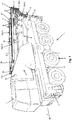
- FIG. 1 a perspective view of a mobile crane designated by 1 is shown.
- the mobile crane 1 essentially comprises an undercarriage 2 and an uppercarriage 3.
- the undercarriage 2 carries counterweights 4 and has four vehicle axles 5, each with two wheels 6 suitable for road use.
- the undercarriage 2 can of course also be equipped with more or less than four vehicle axles 5.
- the undercarriage 2 carries the superstructure 3, which can be pivoted about an essentially vertically oriented axis of rotation D with respect to the undercarriage 2.
- the superstructure 3 and the undercarriage 2 can of course also be rigidly mounted on one another.
- a combined driving and crane cabin 7 is arranged on the superstructure 3 and can be pivoted about a vertical axis K from the front - as seen in the forward direction F of the mobile crane 1 - to the rear and vice versa.
- the combined driving and crane cabin 7 is thus in the driving position behind the superstructure 3 and in the crane operating position on the side next to the superstructure 3.
- a luffing telescopic boom 8 is mounted on the superstructure, which is fully retracted for driving on the road and counter to the forward direction F of the Mobile crane 1 is placed on the undercarriage 2 at a shallow angle starting from a horizontal downward so that guy supports 15 arranged on the telescopic boom 8 and projecting upward do not increase the overall height when the mobile crane 1 is traveling. It is of course also possible to design the driving and crane cab 7 separately from one another.
- the telescopic boom 8 consists in the usual manner of a boom base box 9 and a plurality of extendable and retractable telescopic sections 10a-h and has a guy system 11 in order to achieve an increase in the load with the telescope boom 8 otherwise unchanged. With this guy system telescopic boom 8 with smaller diameters or cross sections can be realized while maintaining the load.
- the guy system 11 essentially consists of a large number of tension rods 16, 16 ', 16a-16h, 16a'-16h', of which the displaceable tension rods 16a-h, 16a'-h 'parallel to and with the telescopic sections 10a-10h. and extendable.
- the boom basic box 9 is connected in the usual manner at its foot to the superstructure 3 via a horizontal luffing axis W and via a luffing cylinder 12 (see Figure 2 ) can be swung up and down.
- the boom base box 9 takes in the telescopic sections 10a-h, which are arranged one inside the other and can be extended and retracted. In each extended state, the telescopic sections 10a-h are connected to one another via bolts, not shown.
- the foot of the respective inner and thus smaller telescopic section 10a-h is bolted to the next outer and larger telescopic section 10a-h or the boom basic box 9 via a suitable bolting position hole.
- the base of the telescopic section 10h is connected to the head 10 of the telescopic section 10g via the bolts (not shown).
- FIG 2 4 is a partial perspective view of the mobile crane 1 according to FIG Figure 1 shown with partially extended telescopic boom 8.
- the innermost and therefore uppermost telescopic section 10h is extended, the remaining telescopic sections 10a-g are still retracted.
- the superstructure 3 is for the crane operation from the position for road travel (see here Figure 1 ) pivoted through 180 °, so that the telescopic boom 8 points in the forward direction F and there is space for the arrangement of counterweights 4 on the rear of the superstructure 3.
- the driving and Crane cabin 7 has now been moved to the side of the superstructure 3 for crane operation.
- a lifting mechanism 14 with a cable drum for lifting and lowering the crane loads is arranged on the boom basic box 9.
- the cable drum of the lifting mechanism 14 points upwards and its rolling axis is arranged at right angles to the longitudinal direction L of the telescopic boom 8 (see also Figure 3 ).
- a lifting cable 18 is wound up and unwound from the lifting mechanism 14 and runs from the lifting mechanism 14 along and above the telescopic boom 8 to the end of the last telescopic section 10h.
- At the end of the last telescopic shot 10h there is a deflection roller 19 and a guide roller 31 (see Figure 3 ), over which the hoisting rope 18 is guided.
- the guy system 11 essentially comprises V- and fork-shaped guy supports 15, each of which is seen at the outer end of a head 9a of the boom base box 9, as seen in the longitudinal direction L of the telescopic boom 8 or a head 10 of each telescopic section 10a-h are arranged.
- Each V- and fork-shaped guy support 15 comprises a left leg 15a and a right leg 15a '.
- Each of the left and right legs 15, 15a ' consists of a lower part 15b, 15b' and an upper part 15c, 15c '.
- the two lower parts 15b, 15b ' when the telescopic boom 8 is horizontally oriented, connect each other on the outside and above in the area of corners of the telescopic sections 10a-h, which are essentially square in cross section, or of the basic boom box 9, which is essentially square in cross section, and extend obliquely below approximately an angle of 45 ° upwards and outwards.
- the upper parts 15c, 15c' adjoin one another at an angle of approximately 45 ° so that they extend vertically upwards.
- the telescopic boom 8 is braced by means of the fixed jib base frame tie rods 16, 16 'on the jib base frame 9 and the displaceable tie rods 16a-h, 16a'-h each in connection with the guy supports 15.
- the left and right stationary tie rods 16, 16' run in a transport position at a flat angle to the longitudinal direction L of the telescopic boom 8 and are each fixed at one end to the associated guy support 15 in the transition region between its lower and upper legs 15b, 15b ', 15c, 15c' and connected to the other end in the lateral region of the foot of the boom base box 9.
- the clamping forces acting on the first guy support 15 of the basic boom box 9 are thus introduced into the basic boom box 9 via the fixed clamping rods 16, 16.
- the displaceable tension rods 16a-h, 16a'-h ' are placed on the left and right guide holders 13a, 13b in the retracted state.
- Each of these guide holders 13a, 13b is designed as an upwardly open, flat U-shaped profile with U-shaped guide tracks for each of the displaceable tension rods 16a-h, 16a'-h 'and serves as a magazine for the displaceable tension rods 16a-h, 16a' -h 'when the telescopic boom 8 is retracted.
- the guide holders 13a, 13b are each pivoted at the head about an articulation point H, H' with a horizontal axis at the upper end of the legs 15a, 15a 'of the guy support 15 at the head of the boom base box 9a.
- the guide brackets 13a, 13b are mounted with a set-up mechanism 30 at the foot of the boom base box 9.
- the guide holders 13a, 13b with the displaceable tension rods 16a-h, 16a'-h ' are pivoted up from their transport position into an operating position by means of the toggle-type setting mechanism 30 via an auxiliary cylinder. In this operating position, the displaceable tension rods 16a-h, 16a'-h 'and the guide holders 13a, 13b run parallel and above the telescopic boom 8.
- hinge points H, H 'of all displaceable tension rods 16a-h, 16a'-h' and also the guide holder 13a, 13b lie in the transport position of the guide holder 13a, 13b and the telescopic boom 8 on a common, imaginary, horizontal axis.
- displaceable tension rods 16h, 16h ' With respect to an extended pair of the first or uppermost displaceable tension rods 16h, 16h 'is from the Figure 2nd It can be seen that the displaceable tension rods 16h, 16h 'have an articulation point H, H' in the vicinity of the uppermost guy support 15.
- the distance of the articulation point H, H 'to the fixed connection of the displaceable tension rods 16h, 16h' to the uppermost guy support 15 corresponds to the distance of the top guy support 15 to the articulation point H, H 'of the guide brackets 13a, 13b in the transport position of the telescopic boom 8.
- Corresponding pivot points H, H 'and associated distances can also be found in all other displaceable tension rods 16h, 16h', although these are not shown in the drawing.
- FIG 3 a perspective top view is shown diagonally from above of a fully extended telescopic boom 8.
- the guy supports 15 are arranged on each telescopic shot head 10 and on the boom basic box head 9a and are thus spaced apart from one another.
- the legs 15a and 15a 'of the guy support 15 are arranged on the right and left of the telescopic boom 8.
- the opposite upper parts 15c, 15c 'of the guy supports 15 are at a distance b from one another.
- the displaceable tension rods 16h, 16h ' the associated articulation points H, H "are shown in the vicinity of the uppermost guy support 15.
- Each of the displaceable tension rods 16a-h, 16a'-h' is thus formed in two parts.
- the lower parts 15b, 15b ' have a first length l and the upper parts 15c, 15c' have a second length l '. Since the displaceable tension rods 16a-h, 16a'-h 'are arranged in the operating position essentially in alignment with one another along the telescopic boom 8, the first and second lengths l, l' are to be adapted accordingly, since the diameter of the telescopic sections 10 ah is based on this Remove boom base box 9 and thus this is compensated for by an associated increase in lengths l, l '.
- FIG 4 shows a detailed view of a guy support 15 on a boom base box 9 of the telescopic boom 8. Since none in the present case displaceable tension rods 16a-h, 16a'-h 'are stored in the guide holder 13a, 13b, all telescopic sections 10a-10h are at least partially extended. It can also be seen that an opening angle ⁇ of the two legs 15a and 15a 'is approximately 45 ° to 135 °, preferably 90 °.
- the two legs 15a, 15a ' lie in a common, imaginary plane which is oriented at right angles to a longitudinal direction L of the telescopic boom 8.
- the lower parts 15b, 15b 'of the two legs 15a, 15a' themselves have an elongated triangle-like shape with the respectively adjoining vertical upper part 15c, 15c ', one base side of the triangle resting on the telescopic section 10a-h or on the boom base box 9 .
- an actuatable holding mechanism 17 is arranged in each case for fixing the displaceable tension rods 16a-h, 16a'-h '.
- the displaceable tension rods 16a-h, 16a'-h ' are each fixedly arranged on the associated upper part 15c, 15c' of a guy support 15.
- An articulation point H, H ' enables pivoting of the displaceable tension rods 16a-h, 16a'-h' inserted in the guide holders 13a, 13b into the transport position.
- the displaceable tension rods 16a-h, 16a'-h ' are fixed via the respective holding mechanism 17 at the upper ends of the upper parts 15c, 15c' of the legs 15a, 15a '.
- Each of the holding mechanisms 17 essentially consists of a left or right locking element 24a, 24b, which engages with a left or right recess 23a-c, 23a'-c 'in the displaceable tensioning rods 16a-h, 16a', which is designed to complement this in a form-fitting manner.
- -h ' can be brought (see also Figures 3 and 5 ).
- each displaceable tension rod 16a-h, 16a'-h ', three recesses 23a-c, 23a'-c' are arranged in the longitudinal direction at a distance and in succession: a first recess 23a, 23a 'at the beginning of the displaceable tension rods 16a-h , 16a'-h 'for fixing in the retracted state of the respective telescopic section 10a-h, a second recess 23b, 23b' in the middle of the displaceable tension rods 16a-h, 16a'-h 'for fixing in the case of a respective half-extended telescopic section 10a-h and a third recess 23c, 23c 'at the end of the displaceable tension rods 16a-h, 16a'-h' for fixing to a respective fully extended telescopic section 10a-h.
- the Figure 5 shows a detailed view of seven of the eight guy supports 15 when the telescopic sections 10a-g are retracted.
- the displaceable tension rods 16a-g, 16a'-g ' are also retracted and are received by the guide holder 13a, 13b.
- the displaceable tensioning rods 16a-h, 16a'-h ' run on rollers 27a-g, 27a'-g' which are arranged in and next to the upper legs 15c, 15c 'of the legs 15a, 15a' .
- the upper part 15c, 15c 'of the legs 15a, 15a' is each provided with an opening 32a-g, 32a'-g 'in which the displaceable tensioning rods 16a-h, 16a'-h' during their inward and outward movement be performed.
- These openings 32a-g, 32a'-g ' are delimited at the bottom by the rollers 27a-g, 27a'-g' and at the top by the locking elements 24a, 24b.
- a lateral boundary is provided by walls of the upper parts 15c, 15c '.
- the holding mechanism 17 for fixing the displaceable tension rods 16a-h, 16a'-h 'in the opening 32a-g, 32a'-g' to the desired extension length is shown.
- the respective locking element 24a, 24b can be moved in a sliding direction s 'and thus in the longitudinal direction of the respective upper part 15c, 15c' from a lower locking position into an upper unlocking position. In the locking position, the locking element 24a, 24b engages with the respective recess 23a, 23a 'of the respective displaceable tension rod 16a-h, 16a'-h'.
- the locking element 24a, 24b In the unlocked position, the locking element 24a, 24b is shifted upwards in the sliding direction s 'so that the locking element 24a, 24b has moved out of the respective recess 23a, 23a' and thus moves above the respective displaceable tensioning rod 16a-h, 16a'- h 'is located.
- the locking elements 24a, 24b are each prestressed in the locking position via an upper spring element 28a ', which acts downwards in the sliding direction s', so that a drive is required for moving in the unlocking position.
- This drive for moving the locking elements 24a, 24b is designed as follows.
- Each of the locking elements 24a, 24b is laterally connected to a left or right upper sliding element 25a ', 25b', which extends downward to the beginning of the upper part 15c, 15c '.
- the left and right wedge pieces 22a, 22b are attached to upper ends of the right and left lower slide members 25a, 25b, respectively.
- sliding elements 25a, 25b have a sliding roller 26a, 26b at the lower end, are displaceable in the longitudinal direction of the lower parts 15b, 15b 'in a sliding direction s and end at the lower end of the lower parts 15b, 15b' and are thus the surface of the respective one Telescopic shot 10a-h facing.
- the lower sliding elements 25a, 25b are each prestressed in the direction of the lower end of the lower parts 15b, 15b via a lower spring element 28a, 28b and thus in the locking position of the locking elements 24a, 24b.
- a drive with left and right sliding cylinders 29a, 29b is provided.
- a sliding wedge 21a, 21b (see also here Figure 4 ) attached, on which a ramp-like lower end is provided.
- the sliding wedges 21a, 21b are displaced below the left and right sliding rollers 26a, 26b by extending the sliding cylinders 29a, 29b in order to raise the lower sliding element 25a, 25b, on which the sliding rollers 26a, 26b act, in the sliding direction S.
- the sliding cylinders 29a, 29b are arranged on the right and left in the area of the upper corners of the boom base box 9 and can be moved in and out in a sliding direction S.
- the innermost telescopic section 10h of the telescopic boom 8 is extended together with its guy support 15. Since the displaceable tensioning rods 16h, 16h 'in the rod fixed points 20h, 20h' of the legs 15a and 15a 'of the guy support 15 are fastened to the guy support 15, they are simultaneously taken along in the longitudinal direction L of the telescopic boom 8 and thus pulled out of the guide holders 13a and 13b .
- the displaceable tensioning rods 16h, 16h ' are guided through the openings 32g, 32g' and on the rollers 27a, 27a 'of the guy supports 15 of the telescope section 10g which is not yet extended in the longitudinal direction L.
- the displaceable tension rods 16h, 16h ' are fixed on the legs 15a and 15a' by the two holding mechanisms 17 of the adjacent telescopic section 10g in the usual manner at half and full extension length.
- each telescopic section 10a-h which then define a telescopic section 10a-h in a full or half or otherwise pre-selected extension path of the telescopic section 10a-h.
- the displaceable tension rods 16a-g, 16a-g ' are then successively and sectionally clamped between the respective guy supports 15 of the telescopic sections 10a-f and the boom base box 9 in the same way.
Description
Die Erfindung betrifft einen Teleskopausleger eines Mobilkrans mit mehreren aus einem Auslegergrundkasten aus einer Transportstellung in eine Betriebsstellung austeleskopierbaren Teleskopschüssen und mit einem Abspannsystem zum Abspannen des Teleskopauslegers, welches mehrere aufeinanderfolgend miteinander verbundene Spannstangen umfasst, die ausgehend von dem Auslegergrundkasten über mindestens eine Abspannstütze zu mindestens einem der ausgefahrenen Teleskopausleger verlaufen.The invention relates to a telescopic boom of a mobile crane with a plurality of telescopic sections telescopic from a jib basic box from a transport position into an operating position and with a guy system for bracing the telescopic boom, which comprises a plurality of tie rods connected to one another in succession, starting from the jib basic box via at least one guy support to at least one of the extended telescopic boom run.
Außerdem betrifft die Erfindung ein Verfahren zum Abspannen eines Teleskopauslegers eines Mobilkrans, bei dem mehrere aufeinanderfolgend miteinander verbundene Spannstangen zwischen einem Auslegergrundkasten eines Teleskopauslegers und mindestens einem angrenzenden Teleskopschuß des Teleskopauslegers abgespannt werden.The invention also relates to a method for bracing a telescopic boom of a mobile crane, in which a plurality of clamping rods connected in succession are braced between a basic boom of a telescopic boom and at least one adjacent telescopic section of the telescopic boom.
Dokument
Des Weiteren offenbart die deutsche Patentschrift
Ferner ist aus der europäischen Patentschrift
Auch ist aus der weiteren europäischen Patentschrift
Das deutsche Patent
Das Patent
Auch das chinesische Gebrauchsmuster
Der Erfindung liegt die Aufgabe zugrunde, einen Teleskopausleger für einen Mobilkran mit einem Stangenabspannsystem und ein Abspannverfahren hierfür zu schaffen, die sich durch eine leichtere Bauweise und verbesserte Handhabung im Straßenbetrieb sowie einer Erhöhung der Traglast bei unveränderten Teleskopausleger-Maßen auszeichnen.The invention has for its object to provide a telescopic boom for a mobile crane with a rod guy system and a guy method for this, which are characterized by a lighter design and improved handling in road operation and an increase in load capacity with unchanged telescopic boom dimensions.
Diese Aufgabe wird durch einen Teleskopausleger mit den Merkmalen des Anspruchs 1 und ein Verfahren mit den Merkmalen des Anspruchs 12 gelöst. In den Unteransprüchen 2 bis 11 sind vorteilhafte Ausgestaltungen der Erfindung angegeben.This object is achieved by a telescopic boom with the features of claim 1 and a method with the features of
Erfindungsgemäß wird bei einem Teleskopausleger eines Mobilkrans mit mehreren aus einem Auslegergrundkasten aus einer Transportstellung in eine Betriebsstellung austeleskopierbaren Teleskopschüssen und mit einem Abspannsystem zum Abspannen des Teleskopauslegers, welches mehrere aufeinanderfolgend miteinander verbundene Spannstangen umfasst, die ausgehend von dem Auslegergrundkasten über mindestens eine Abspannstütze zu mindestens einem der ausgefahrenen Teleskopausleger verlaufen, eine Erhöhung der Traglast und eine leichtere Bauweise dadurch erreicht, dass an dem Auslegergrundkasten ein Führungshalter für die verschiebbaren Spannstangen angeordnet ist, der die verschiebbaren Spannstangen in der Transportstellung des Teleskopauslegers aufnimmt und in der Betriebsstellung jeweils mindestens eine der verschiebbaren Spannstangen an einer der Abspannstützen jeweils am äußeren Ende des Teleskopschuss-Kopfes fest angelenkt ist und am gegenüberliegenden Ende an einer benachbarten Abspannstütze eines benachbarten Teleskopschuss-Kopfes an einem Haltemechanismus festlegbar ist. Hierdurch werden auch verkürzte Rüstzeiten zwischen Straßen- und Kranbetrieb erreicht. Das gesamte Abspannsystem wird am Mobilkran, insbesondere am Auslegergrundkasten, mitgeführt. Hierbei sind vorteilhafter Weise die verschiebbaren Spannstangen jeweils aus dem zugeordneten Führungshalter ausfahrbar beziehungsweise in diesen einfahrbar.According to the invention, in the case of a telescopic boom of a mobile crane with a plurality of telescopic sections telescopic from a jib basic box from a transport position into an operating position and with a guy system for guying the telescopic boom, which comprises a plurality of clamping rods connected to one another in succession, starting from the jib main box via at least one guy support to at least one of the extend telescopic boom, an increase in the load and a lighter design achieved that a guide holder for the sliding tension rods is arranged on the boom base box, which receives the sliding tension rods in the transport position of the telescopic boom and in the operating position at least one of the sliding tension rods on one the guy supports are articulated at the outer end of the telescopic head and at the opposite end to an adjacent one Guy support one adjacent telescopic shot head can be fixed to a holding mechanism. This also reduces set-up times between road and crane operations. The entire guy system is carried on the mobile crane, especially on the jib base box. In this case, the displaceable tension rods can advantageously be extended from the assigned guide holder or retracted into the latter.
Eine platzsparende Umsetzung des Abspannsystems wird dadurch erreicht, dass jede Abspannstütze jeweils am äußeren Ende eines Auslegergrundkasten-Kopfes oder eines Teleskopschuss-Kopfes angeordnet ist.A space-saving implementation of the guy system is achieved in that each guy support is arranged at the outer end of a boom head box head or a telescopic shot head.
In einer weiteren Ausgestaltung der Erfindung ist vorgesehen, dass jeweils am Auslegergrundkasten und an jedem Teleskopschuss eine Abspannstütze angeordnet ist. Der Teleskopausleger kann daher an mehreren Punkten abgespannt werden, welches wiederum die Stabilität der Abspannung erhöht und die Traglast des Teleskopauslegers verbessert. Dadurch kann ferner bei gleicher Traglast eine leichtere und kleinere Bauweise umgesetzt werden.
Das Abspannsystem wird dadurch konstruktiv vereinfacht, dass jede Abspannstütze eine Öffnung für die durchzuführenden verschiebbaren Spannstangen aufweist und im Bereich der Öffnung der Haltemechanismus für die jeweilige verschiebbare Spannstange angeordnet ist.In a further embodiment of the invention it is provided that a guy support is arranged on the boom base box and on each telescopic section. The telescopic boom can therefore be braced at several points, which in turn increases the stability of the bracing and improves the load capacity of the telescopic boom. This also allows a lighter and smaller design to be implemented with the same load.
The guying system is simplified in terms of design in that each guying support has an opening for the displaceable tensioning rods to be carried out and the holding mechanism for the respective displaceable tensioning rod is arranged in the region of the opening.
Für eine besonders einfache Umsetzung des Abspannsystems ist vorgesehen, dass der Haltemechanismus ein bewegliches Riegelelement umfasst, mit dem die jeweilige Spannstange in der Öffnung in der Betriebsstellung durch einen Eingriff in eine Aussparung in der jeweiligen Spannstange festlegbar ist.For a particularly simple implementation of the guy system, it is provided that the holding mechanism comprises a movable locking element with which the respective tension rod can be fixed in the opening in the operating position by engaging in a recess in the respective tension rod.
Eine weitere Verbesserung der Stabilität und der Traglast des Teleskopauslegers ist dadurch gegeben, dass jede Abspannstütze zwei Schenkel umfasst, die in Längsrichtung des Teleskopauslegers gesehen von einer Mitte des Teleskopauslegers rechts und links am Teleskopausleger angeordnet sind und einen Winkel von 45° bis 135°, bevorzugter Weise 90°, einschließen.A further improvement in the stability and the load capacity of the telescopic boom is given in that each guy support comprises two legs, which are arranged on the right and left of the telescopic boom as seen in the longitudinal direction of the telescopic boom and an angle of 45 ° to 135 °, more preferably, is preferred Include 90 ° way.
In einer weiteren Ausgestaltung der Erfindung ist vorgesehen, dass an jedem Schenkel jeder Abspannstütze mindestens eine Spannstange fest angelenkt und/oder an dem Haltemechanismus festlegbar ist.In a further embodiment of the invention it is provided that at least one tension rod is articulated and / or firmly attached to each leg of each guy support can be fixed on the holding mechanism.
In üblicher Weise ist vorgesehen, dass die aufeinander folgenden Teleskopschüsse und der Auslegergrundkasten aneinander feststellbar sind.In a conventional manner, it is provided that the successive telescopic sections and the boom base box can be locked together.
Außerdem wird die Bauhöhe des Mobilkrans für den Straßenbetrieb dadurch eingehalten, dass durch einen Aufstellmechanismus, welcher die Führungshalter des Abspannsystems über eine Abspannstütze mit dem Auslegergrundkasten verbindet, die Führungshalter aus einer Transportstellung in eine Betriebsstellung aufstellbar sind und in der Betriebsstellung die Führungshalter und die darauf ruhenden verschiebbaren Spannstangen parallel zur einer Längsrichtung und oberhalb des Teleskopauslegers verlaufen.In addition, the overall height of the mobile crane for road operation is maintained by the fact that a guide mechanism, which connects the guiding brackets of the guy system to the jib base box via a guy support, allows the guiding brackets to be set up from a transport position to an operating position and the guiding brackets and those resting on them in the operating position slidable tie rods run parallel to a longitudinal direction and above the telescopic boom.
Um eine platzsparende Verschwenkbarkeit der Führungshalter und verschiebbaren Spannstangen zu erreichen, ist vorgesehen, dass die Führungshalter über Gelenkpunkte aus der Transportstellung in die Betriebsstellung schwenkbar sind, die Gelenkpunkte im Verlauf der Führungshalter und an die Abspannstütze angrenzend angeordnet sind, die verschiebbaren Spannstangen in der Transportstellung auf den Führungshaltern mit den Gelenkpunkten der Führungshalter fluchtende Gelenkpunkte aufweisen.In order to achieve a space-saving pivotability of the guide holders and displaceable tension rods, it is provided that the guide holders can be pivoted from the transport position into the operating position via articulation points, the pivot points are arranged in the course of the guide holders and adjacent to the guy support, the displaceable tension rods in the transport position have the guide brackets aligned with the articulation points of the guide brackets.
In Bezug auf die erste Abspannstütze an dem Kopf des Auslegergrundkastens ist eine Abspannung über linke und rechte ortsfeste Spannstangen an dem Auslegergrundkasten im Bereich dessen Fußes vorgesehen.With regard to the first guy support on the head of the boom base box, a guy is provided on the left and right stationary tension rods on the boom base box in the region of its foot.
Ein vereinfachtes und platzsparendes Verfahren zum Abspannen eines Teleskopauslegers, bei dem mehrere aufeinanderfolgend miteinander verbundene Spannstangen zwischen einem Auslegergrundkasten eines Teleskopauslegers und mindestens einem angrenzenden Teleskopschuß des Teleskopauslegers abgespannt werden, wird dadurch erreicht, dass gemeinsam mit einem aufeinanderfolgenden Ausfahren der einzelnen Teleskopschüsse aus dem Auslegergrundkasten jeweils einer der Spannstangen aus einem Führungshalter aus einer Transportstellung in eine Betriebsstellung ausgefahren wird und jede Spannstange in der Betriebsstellung an einer Abspannstütze des benachbarten Teleskopschusses über einen Haltemechanismus festgelegt wird.A simplified and space-saving method for bracing a telescopic boom, in which a plurality of clamping rods connected in succession are braced between a boom base box of a telescopic boom and at least one adjacent telescopic section of the telescopic boom, is achieved in that, together with a successive extension of the individual telescopic sections from the boom basic box, one each the tension rods are extended from a guide holder from a transport position into an operating position and each tension rod is fixed in the operating position on a guy support of the adjacent telescopic section by means of a holding mechanism.
Ein Ausführungsbeispiel der Erfindung wird nachfolgend näher erläutert. Es zeigen:
-
Figur 1 eine perspektivische Ansicht eines Mobilkrans mit einem Teleskopausleger, -
Figur 2Figur 1 mit teilweise ausgefahrenem Teleskopausleger, -
Figur 3 -
Figur 4 -
Figur 5Figur 2
-
Figure 1 a perspective view of a mobile crane with a telescopic boom, -
Figure 2 a partial perspective view of a mobile crane according toFigure 1 with partially extended telescopic boom, -
Figure 3 a top perspective view of a fully extended telescopic boom, -
Figure 4 a detailed view of a guy support on a boom base box of the telescopic boom and -
Figure 5 a detailed view of the guy supports on the telescopic boom in the position accordingFigure 2 with open latch elements.
In
Der Teleskopausleger 8 besteht in üblicher Weise aus einem Auslegergrundkasten 9 und mehreren aus- und einfahrbaren Teleskopschüssen 10a-h und hat ein Abspannsystem 11, um eine Erhöhung der Traglast bei sonst unverändertem Teleskopausleger 8 zu erreichen. Auch sind mit diesem Abspannsystem bei Beibehaltung der Traglast Teleskopausleger 8 mit geringeren Durchmessern oder Querschnitten realisierbar. Das Abspannsystem 11 besteht im Wesentlichen aus einer Vielzahl von Spannstangen 16, 16', 16a-16h, 16a'-16h', wovon die verschiebbaren Spannstangen 16a-h, 16a'-h' parallel zu und mit den Teleskopschüssen 10a-10h ein- und ausfahrbar sind. In der
Der Auslegergrundkasten 9 ist in üblicher Weise an seinem Fuß über eine horizontale Wippachse W mit dem Oberwagen 3 verbunden und über einen Wippzylinder 12 (siehe
In
Außerdem ist aus der
Neben der Vielzahl von Spannstangen 16, 16', 16a-16h, 16a'-16h' umfasst das Abspannsystem 11 im Wesentlichen v- und gabelförmige Abspannstützen 15, die jeweils am in Längsrichtung L des Teleskopauslegers 8 gesehen äußeren Ende eines Kopfes 9a des Auslegergrundkastens 9 beziehungsweise eines Kopfes 10 jedes Teleskopschusses 10a-h angeordnet sind. Jede v- und gabelförmige Abspannstütze 15 umfasst einen linken Schenkel 15a und einen rechten Schenkel 15a'. Jeder der linken und rechten Schenkel 15, 15a' besteht aus einem unteren Teil 15b, 15b' und einem oberen Teil 15c, 15c'. Die beiden unteren Teile 15b, 15b' schließen sich bei horizontal ausgerichtetem Teleskopausleger 8 gesehen jeweils außen und oben im Bereich von Ecken der im Querschnitt im Wesentlichen viereckigen Teleskopschüsse 10a-h beziehungsweise des im Querschnitt im Wesentlichen viereckigen Auslegergrundkastens 9 an und erstrecken sich schräg unter etwa einem Winkel von 45° nach oben und außen. An die oberen freien Enden der unteren Teile 15b, 15b' schließen sich in einteiliger Weise die oberen Teile 15c, 15c' schräg unter etwa einem Winkel von 45° an, so dass diese sich vertikal nach oben erstrecken.In addition to the large number of
Ein Abspannen des Teleskopauslegers 8 erfolgt durch die ortsfesten Auslegergrundkasten-Spannstangen 16, 16' am Auslegergrundkasten 9 und die verschiebbaren Spannstangen 16a-h, 16a'-h jeweils in Verbindung mit den Abspannstützen 15. Die linken und rechten ortsfesten Spannstangen 16, 16' verlaufen in einer Transportstellung unter einem flachen Winkel zu der Längsrichtung L des Teleskopauslegers 8 und sind jeweils mit einem Ende an der zugehörigen Abspannstütze 15 im Übergangsbereich zwischen dessen unteren und oberen Schenkel 15b, 15b', 15c, 15c' befestigt und mit dem anderen Ende im seitlichen Bereich des Fußes des Auslegergrundkastens 9 verbunden. Über die ortsfesten Spannstangen 16, 16 werden somit die an der ersten Abspannstütze 15 des Auslegergrundkasten 9 angreifenden Spannkräfte in den Auslegergrundkasten 9 eingeleitet. Die verschiebbaren Spannstangen 16a-h, 16a'-h' sind im eingefahrenen Zustand auf linken und rechten Führungshaltern 13a, 13b abgelegt. Jeder dieser Führungshalter 13a, 13b ist als nach oben offenes flaches u-förmiges Profil mit u-förmigen Führungsbahnen für jede der verschiebbaren Spannstangen 16a-h, 16a'-h' ausgebildet und dient als Magazin für die verschiebbaren Spannstangen 16a-h, 16a'-h' bei eingefahrenem Teleskopausleger 8. Die Führungshalter 13a, 13b sind jeweils am Kopf um einen Gelenkpunkt H, H' mit einer horizontalen Achse schwenkbar an dem oberen Ende des Schenkels 15a, 15a' der Abspannstütze 15 am Kopf des Auslegergrundkastens 9a angelenkt. Am gegenüberliegenden Fuß sind die Führungshalter 13a, 13b mit einem Aufstellmechanismus 30 am Fuß des Auslegergrundkastens 9 gelagert. Vor einem Aufwippen und einem Ausfahren des Teleskopauslegers 8 werden die Führungshalter 13a, 13b mit den verschiebbaren Spannstangen 16a-h, 16a'-h' durch den kniehebelartigen Aufstellmechanismus 30 über einen Hilfszylinder aus Ihrer Transportstellung in eine Betriebsstellung hochgeschwenkt. In dieser Betriebsstellung verlaufen die verschiebbaren Spannstangen 16a-h, 16a'-h' und die Führungshalter 13a, 13b parallel und oberhalb des Teleskopauslegers 8.The
Um die vorbeschriebene Bewegung der Führungshalter 13a, 13b aus der Transportstellung in die Betriebsstellung zu ermöglichen und auch den Vorteil der verringerten Bauhöhe in der Transportstellung zu erhalten, müssen nicht nur die Führungshalter 13a, 13b, sondern auch die verschiebbaren Spannstangen 16a-h, 16a'-h' gelenkig mit Gelenkpunkten H, H' ausgebildet sein. Jede der verschiebbaren Spannstangen 16a-h, 16a'-h' ist somit zumindest zweiteilig mit einem Gelenkpunkt H, H' ausgebildet. Diese Gelenkpunkte H, H' aller verschiebbaren Spannstangen 16a-h, 16a'-h' und auch der Führungshalter 13a, 13b liegen in der Transportstellung der Führungshalter 13a, 13b und des Teleskopauslegers 8 auf einer gemeinsamen, gedachten, horizontalen Achse. In Bezug auf ein ausgefahrenes Paar der ersten beziehungsweise obersten verschiebbaren Spannstangen 16h, 16h' ist aus der
Die im ausgefahrenen Zustand des Teleskopzylinders 8 jeweils über die Abspannstützen 15 miteinander verbundenen, verschiebbaren Spannstangen 16a-h, 16a'-h bilden somit über die Vielzahl der Gelenkpunkte H, H' eine seilartige, flexible Konstruktion, ähnlich einer Gliederkette.The
In
Des Weiteren ist aus der
In den oberen Teilen 15c, 15c' der Schenkel 15a, 15a' ist jeweils ein betätigbarer Haltemechanismus 17 zum Feststellen der verschiebbaren Spannstangen 16a-h, 16a'-h' angeordnet. Wie bereits zuvor beschrieben sind die verschiebbaren Spannstangen 16a-h, 16a'-h' jeweils an dem zugehörigen oberen Teil 15c, 15c' einer Abspannstütze 15 fest angeordnet. Ein Gelenkpunkt H, H' ermöglicht ein Verschwenken der in die Führungshalter 13a, 13b eingefahren verschiebbaren Spannstangen 16a-h, 16a'-h' in die Transportstellung. An dem gegenüberliegenden Ende werden die verschiebbaren Spannstangen 16a-h, 16a'-h' über den jeweiligen Haltemechanismus 17 an den oberen Enden der oberen Teile 15c, 15c' der Schenkel 15a, 15a' festgelegt. Jeder der Haltemechanismen 17 besteht im Wesentlichen aus einem linken beziehungsweise rechten Riegelelement 24a, 24b, das in Eingriff mit einer entsprechend hierzu formschlüssig ergänzend ausgebildeten linken oder rechten Aussparung 23a-c, 23a'-c' in den verschiebbaren Spannstangen 16a-h, 16a'-h' gebracht werden kann (siehe hierzu auch
Auch ist aus der
Die
Auch ist in der
Dieser Antrieb zum Bewegen der Riegelelemente 24a, 24b ist wie folgt ausgebildet. An jedes der Riegelelemente 24a, 24b schließt sich seitlich ein linkes beziehungsweise rechtes oberes Schiebeelement 25a', 25b' an, das sich nach unten an den Beginn des oberen Teils 15c, 15c' erstreckt. Dort liegt es auf linken und rechten Keilstücken 22a, 22b auf, die jeweils als Schiebekulisse für eine Bewegung der oberen Schiebeelemente 25a', 25b' in Schieberichtung s' und mechanische Kraftumlenkung dienen. Die linken und rechten Keilstücke 22a, 22b sind jeweils an oberen Enden vom rechten und linken unteren Schiebeelement 25a, 25b befestigt. Diese Schiebeelemente 25a, 25b weisen am unteren Ende eine Schieberolle 26a, 26b auf, sind in Längsrichtung der unteren Teile 15b, 15b' verschiebbar in einer Schieberichtung s und enden am unteren Ende der unteren Teile 15b, 15b' und sind somit der Oberfläche des jeweiligen Teleskopschusses 10a-h zugewandt. Wie die oberen Schiebeelemente 25a', 25b' sind auch die unteren Schiebeelemente 25a, 25b jeweils über ein unteres Federelement 28a, 28b in Richtung des unteren Endes der unteren Teile 15b, 15b vorgespannt und somit in Verriegelungsstellung der Riegelelemente 24a, 24b. Um das jeweilige untere Schiebeelement 25a, 25b in Schieberichtung s nach oben bewegen zu können und somit die Riegelelemente 24a, 24b aus der Verriegelungsstellung in die Entriegelungsstellung zu bringen, ist ein Antrieb mit einem linken und einem rechten Schiebezylinder 29a, 29b vorgesehen. An einem freien Ende einer Kolbenstange der Schiebezylinder 29a, 29b ist jeweils ein Schiebekeil 21a, 21b (siehe hierzu auch
Da zum Zeitpunkt der Betätigung der jeweiligen Riegelelemente 24a, 24b aus der Verriegelungsstellung in die Entriegelungsstellung die jeweiligen Abspannstützen 15 noch örtlich an den Kopf 9a des Auslegergrundkastens 9 angrenzen, können alle Riegelelemente 24a, 24b nacheinander von den gleichen Schiebezylindern 29a, 29b über die Schiebekeile 21a, 21b betätigt werden.Since at the time of actuation of the
Nachfolgend wird anhand der
- 11
- MobilkranMobile crane
- 22nd
- UnterwagenUndercarriage
- 33rd
- OberwagenSuperstructure
- 44th
- GegengewichteCounterweights
- 55
- FahrzeugachseVehicle axle
- 66
- Räderbikes
- 77
- Fahr- und KrankabineDriving and crane cabin
- 88th
- TeleskopauslegerTelescopic boom
- 99
- AuslegergrundkastenBoom basic box
- 9a9a
- Kopf des AuslegergrundkastensHead of the boom base box
- 1010th
- Kopf eines TeleskopschussesHead of a telescopic shot
- 10a-h10a-h
- TeleskopschüsseTelescopic shots
- 1111
- AbspannsystemGuy system
- 1212th
- WippzylinderRocker cylinder
- 13a13a
- linker Führungshalterleft guide bracket
- 13b13b
- rechter Führungshalterright guide bracket
- 1414
- HubwerkHoist
- 1515
- AbspannstützeGuy support
- 15a15a
- linker Schenkelleft thigh
- 15a'15a '
- rechter Schenkelright leg
- 15b15b
- unteres Teil vom linken Schenkellower part of the left thigh
- 15b'15b '
- unteres Teil vom rechten Schenkellower part of the right leg
- 15c15c
- oberes Teil vom linken Schenkelupper part of the left thigh
- 15c'15c '
- oberes Teil vom rechten Schenkelupper part of the right leg
- 1616
- linke ortsfeste Spannstangeleft stationary tension rod
- 16'16 '
- rechte ortsfeste Spannstangeright fixed tension rod
- 16a-h16a-h
- linke verschiebbare Spannstangenleft sliding tension rods
- 16a'-h'16a'-h '
- rechte verschiebbare Spannstangenright sliding tension rods
- 1717th
- HaltemechanismusHolding mechanism
- 1818th
- HubseilHoist rope
- 1919th
- UmlenkrollePulley
- 20a-h20a-h
- linke Stangenfestpunkteleft pole fixed points
- 20a'-h'20a'-h '
- rechte Stangenfestpunkteright pole fixed points
- 21a21a
- linker Schiebekeilleft sliding wedge
- 21b21b
- rechter Schiebekeilright sliding wedge
- 22a22a
- linkes Keilstückleft wedge piece
- 22b22b
- rechtes Keilstückright wedge
- 23a-c23a-c
- linke Aussparungenleft recesses
- 23a'-c'23a'-c '
- rechte Aussparungenright cutouts
- 24a24a
- linkes Riegelelementleft locking element
- 24b24b
- rechtes Riegelelementright locking element
- 25a25a
- linkes unteres Schiebeelementlower left sliding element
- 25b25b
- rechtes unteres Schiebeelementlower right sliding element
- 25a'25a '
- linkes oberes Schiebeelementupper left sliding element
- 25b'25b '
- rechtes oberes Schiebeelementright upper sliding element
- 26a26a
- linke Schieberolleleft sliding roller
- 26b26b
- rechte Schieberolleright sliding roller
- 27a-g27a-g
- linke Laufrollenleft casters
- 27a'-g'27a'-g '
- rechte Laufrollenright casters
- 28a28a
- linkes unteres Federelementlower left spring element
- 28a'28a '
- linkes oberes Federelementtop left spring element
- 28b28b
- rechtes unteres Federelementright lower spring element
- 28b'28b '
- rechtes oberes Federelementright upper spring element
- 29a29a
- linker Schiebezylinderleft sliding cylinder
- 29b29b
- rechter Schiebezylinderright sliding cylinder
- 3030th
- AufstellmechanismusOpening mechanism
- 3131
- FührungsrolleLeadership role
- 32a-g32a-g
- linke Öffnungenleft openings
- 32a'-g'32a'-g '
- rechte Öffnungenright openings
- aa
- ÖffnungswinkelOpening angle
- bb
- Breitewidth
- DD
- DrehachseAxis of rotation
- FF
- VorwärtsfahrtrichtungForward direction
- HH
- linke Gelenkpunkteleft hinge points
- H'H'
- rechte Gelenkpunkteright hinge points
- KK
- vertikale Achsevertical axis
- ll
- erste Längefirst length
- l'l '
- zweite Längesecond length
- LL
- LängsrichtungLongitudinal direction
- ss
- SchieberichtungSliding direction
- s's'
- SchieberichtungSliding direction
- SS
- SchieberichtungSliding direction
- WW
- WippachseSeesaw axis
Claims (12)
- Telescoping jib (8) of a mobile crane (1) comprising a plurality of telescoping sections (10a-h) which can be telescoped out of a jib basic box (9) from a transport position to an operating position, and comprising a guying system (11) for guying the telescoping jib (8), which comprises a plurality of successively mutually connected tension rods (16a-h, 16a'-h') which extend from the jib basic box (9) via at least one guying support (15) to at least one of the extended telescoping jibs (8),
characterised in that
a guide holder (13a, 13b) for the tension rods (16a-h, 16a'-h') is arranged on the jib basic box (9) and receives the tension rods (16a-h, 16a'-h') in the transport position of the telescoping jib (8) and, in the operating position, in each case at least one of the displaceable tension rods (16a-h, 16a'-h') on one of the guying supports (15) is fixedly articulated in each case to the outer end of the telescoping section head (10) and can be fixed to a holding mechanism (17) on the opposite end on an adjacent guying support (15) of an adjacent telescoping section head (10). - Telescoping jib (8) as claimed in claim 1, characterised in that each guying support (15) is arranged in each case at the outer end of a jib basic box head (9a) or of a telescoping section head (10).
- Telescoping jib (8) as claimed in claim 1 or 2, characterised in that a guying support (15) is arranged on the jib basic box (9) and each telescoping section (10a-h) respectively.
- Telescoping jib (8) as claimed in any one of claims 1 to 3, characterised in that each guying support (15) has an opening (32a-g, 32a'-g') for the displaceable tension rods (16a-h, 16a'-h') to be guided therethrough and the holding mechanism (17) for the respective displaceable tension rod (16a-h, 16a'-h') is arranged in the region of the opening (32a-g, 32a'-g').
- Telescoping jib (8) as claimed in claim 4, characterised in that the holding mechanism (17) comprises a movable locking bar element (24a, 24b), by means of which the respective displaceable tension rod (16a-h, 16a'-h') in the opening (32a-g, 32a'-g') can be fixed in the operating position by engagement into a recess (23a-c, 23a'-c') in the respective displaceable tension rod (16a-h, 16a'-h').
- Telescoping jib (8) as claimed in any one of claims 1 to 5, characterised in that each guying support (15) comprises two limbs (15a, 15a') which are arranged on the telescoping jib (8) to the right and left of a centre of the telescoping jib (8), as seen in the longitudinal direction (L) of the telescoping jib (8), and form an angle (a) of 45° to 135°, preferably 90°.
- Telescoping jib (8) as claimed in claim 6, characterised in that at least one displaceable tension rod (16a-h, 16a'-h') is fixedly articulated to each limb (15a, 15a') of each guying support (15) and/or can be fixed to the holding mechanism (17).
- Telescoping jib (8) as claimed in claims 1 to 7, characterised in that the successive telescoping sections (10a-h) and the jib basic box (9) can be secured to one another.
- Telescoping jib (8) as claimed in any one of claims 1 to 8, characterised in that by means of an erecting mechanism (30) which connects the guide holders (13a, 13b) of the guying system (11) to the jib basic box (9) via a guying support (15), the guide holders (13a, 13b) can be erected from a transport position to an operating position and, in the operating position, the guide holders (13a, 13b) and the displaceable tension rods (16a-h, 16a'-h') resting thereon extend in parallel with a longitudinal direction (L) and above the telescoping jib (8).
- Telescoping jib (8) as claimed in claim 9, characterised in that the guide holders (13a, 13b) can be pivoted from the transport position to the operating position via articulation points (H, H'), the articulation points (H, H') are arranged over the course of the guide holders (13a, 13b) and adjoining the guying support, the displaceable tension rods (16a-h, 16a'-h') in the transport position on the guide holders (13a, 13b) have articulation points (H, H') which are aligned with the articulation points (H, H') of the guide holders (13a, 13b).
- Telescoping jib (8) as claimed in any one of claims 1 to 10, characterised in that the guying support (15) on the head (9a) of the jib basic box (9) is guyed to the jib basic box (9) in the region of its foot via left and right, positionally fixed tension rods (16, 16').
- Method for guying a telescoping jib (8) of a mobile crane (1), in particular as claimed in any one of claims 1 to 11, in which a plurality of successively mutually connected, displaceable tension rods (16a-h, 16a'-h') are guyed between a jib basic box (9) of a telescoping jib (8) and at least one adjoining telescoping section (10a-h) of the telescoping jib (8), characterised in that, together with successively extending the individual telescoping sections (10a-h) from the jib basic box (9) in each case one of the displaceable tension rods (16a-h, 16a'-h') is extended from a guide holder (13a, 13b) from a transport position to an operating position and each displaceable tension rod (16a-h, 16a'-h') in the operating position is fixed to a guying support (15) of the adjacent telescoping section (10a-h) via a holding mechanism (17).
Applications Claiming Priority (2)
| Application Number | Priority Date | Filing Date | Title |
|---|---|---|---|
| DE102017101113.7A DE102017101113B3 (en) | 2017-01-20 | 2017-01-20 | Telescopic boom with pole tensioning system for a mobile crane and guying method |
| PCT/EP2018/051105 WO2018134249A1 (en) | 2017-01-20 | 2018-01-17 | Telescoping jib comprising a rod guying system for a mobile crane and guying method therefor |
Publications (2)
| Publication Number | Publication Date |
|---|---|
| EP3519344A1 EP3519344A1 (en) | 2019-08-07 |
| EP3519344B1 true EP3519344B1 (en) | 2020-04-01 |
Family
ID=61005832
Family Applications (1)
| Application Number | Title | Priority Date | Filing Date |
|---|---|---|---|
| EP18700763.8A Active EP3519344B1 (en) | 2017-01-20 | 2018-01-17 | Telescoping jib comprising a rod guying system for a mobile crane and guying method therefor |
Country Status (5)
| Country | Link |
|---|---|
| US (1) | US11130659B2 (en) |
| EP (1) | EP3519344B1 (en) |
| AU (1) | AU2018209160A1 (en) |
| DE (1) | DE102017101113B3 (en) |
| WO (1) | WO2018134249A1 (en) |
Families Citing this family (6)
| Publication number | Priority date | Publication date | Assignee | Title |
|---|---|---|---|---|
| DE102016114837A1 (en) | 2016-08-10 | 2018-02-15 | Terex Global Gmbh | Telescopic boom with guy system for a mobile crane and guying system |
| DE102020129454B4 (en) | 2020-11-09 | 2023-08-17 | Tadano Demag Gmbh | Mobile crane with a boom system |
| DE102020129762B3 (en) | 2020-11-11 | 2022-02-17 | Tadano Demag Gmbh | Telescopic boom of a mobile crane |
| JP2022084003A (en) * | 2020-11-25 | 2022-06-06 | タダノ デマグ ゲーエムベーハー | Telescopic jib system of mobile crane with basic telescopic jib and additional telescopic jib and corresponding method |
| DE102020134714B4 (en) | 2020-12-22 | 2023-09-28 | Tadano Demag Gmbh | Mobile crane with a luffing main boom and an additional boom system |
| DE102022102318A1 (en) | 2022-02-01 | 2023-08-03 | Liebherr-Werk Ehingen Gmbh | Mobile crane with guyed telescopic boom |
Family Cites Families (27)
| Publication number | Priority date | Publication date | Assignee | Title |
|---|---|---|---|---|
| US2449703A (en) | 1948-09-21 | Snatch block | ||
| US1325053A (en) | 1919-12-16 | Telescoping tower | ||
| US3830376A (en) * | 1973-02-16 | 1974-08-20 | Harnischfeger Corp | Telescopic jib and bearing means therefor |
| US4004695A (en) * | 1975-04-16 | 1977-01-25 | Fulton Industries, Inc. | Channel and plate telescopic crane boom |
| DE2917829A1 (en) | 1979-05-03 | 1980-11-13 | Gottwald Kg Leo | VEHICLE CRANE WITH TELESCOPIC BOOM |
| DE3447095C2 (en) | 1984-12-22 | 1995-04-06 | Krupp Ag Hoesch Krupp | Telescopic boom for cranes |
| US4982853A (en) | 1989-02-09 | 1991-01-08 | Hikoma Seisakusho Co., Ltd. | Reinforcement mechanism for multi-stage telescopic boom |
| DE10022658B4 (en) | 1999-06-28 | 2007-10-04 | Terex-Demag Gmbh & Co. Kg | telescopic crane |
| DE10062517C2 (en) | 2000-12-11 | 2002-12-05 | Demag Mobile Cranes Gmbh & Co | telescopic boom |
| DE20020974U1 (en) | 2000-12-12 | 2002-04-25 | Liebherr Werk Ehingen | mobile crane |
| DE10129022B4 (en) | 2001-06-13 | 2005-07-28 | Terex-Demag Gmbh & Co. Kg | Telescopic crane with superlift device |
| DE20203443U1 (en) | 2002-01-02 | 2003-05-15 | Liebherr Werk Ehingen | Telescopic jib has bracing supports pivotable around only one single respective pivot point inclined do that supports spread out in V-form during orientation into operating position |
| DE20208740U1 (en) | 2002-06-05 | 2003-10-09 | Liebherr Werk Ehingen | Mobile telescopic crane has external bracing cables terminating at their upper end in a fixed sleeve engaging with a cable lock trap at full extension |
| DE20219126U1 (en) * | 2002-12-10 | 2004-04-15 | Liebherr-Werk Ehingen Gmbh | telescopic boom |
| DE10315989B4 (en) | 2003-04-08 | 2007-10-25 | Grove U.S. Llc | Clamping system for a mobile telescopic crane |
| DE502004011788D1 (en) * | 2004-12-03 | 2010-11-25 | Manitowoc Crane Group Germany | mobile crane |
| CN201272663Y (en) | 2008-06-30 | 2009-07-15 | 徐州重型机械有限公司 | Telescopic arm crane and its super-lifting apparatus |
| CN101857176B (en) | 2010-07-05 | 2013-04-10 | 三一汽车起重机械有限公司 | Super hoisting device and telescopic-boom hoisting equipment with same |
| WO2012080452A1 (en) | 2010-12-17 | 2012-06-21 | Tadano Faun Gmbh | Mobile telescopic crane |
| CN202558505U (en) | 2012-05-17 | 2012-11-28 | 中联重科股份有限公司 | Superlift device and crane |
| DE202014006460U1 (en) | 2014-08-11 | 2015-11-12 | Liebherr-Werk Ehingen Gmbh | Telescopic boom of a crane with bracing as well as crane |
| CN104555760B (en) | 2014-12-26 | 2016-07-27 | 长沙中联消防机械有限公司 | Telescopic jib structure and engineering truck |
| DE102015202734A1 (en) | 2015-02-16 | 2016-08-18 | Terex Cranes Germany Gmbh | Crane and method for influencing a deformation of a boom system of such a crane |
| DE102015119379B3 (en) | 2015-11-10 | 2017-03-30 | Terex Global Gmbh | Mobile crane and method for bending a main boom extension relative to a main boom of a mobile crane |
| DE102015119381B3 (en) | 2015-11-10 | 2017-04-27 | Terex Global Gmbh | Mobile crane and method for bending a main boom extension relative to a main boom of a mobile crane |
| DE102015120350B3 (en) | 2015-11-24 | 2017-05-24 | Terex Global Gmbh | Mobile crane for bending a main boom extension relative to a main boom of a mobile crane |
| DE102016114837A1 (en) | 2016-08-10 | 2018-02-15 | Terex Global Gmbh | Telescopic boom with guy system for a mobile crane and guying system |
-
2017
- 2017-01-20 DE DE102017101113.7A patent/DE102017101113B3/en not_active Expired - Fee Related
-
2018
- 2018-01-17 WO PCT/EP2018/051105 patent/WO2018134249A1/en unknown
- 2018-01-17 US US16/477,651 patent/US11130659B2/en active Active
- 2018-01-17 AU AU2018209160A patent/AU2018209160A1/en not_active Abandoned
- 2018-01-17 EP EP18700763.8A patent/EP3519344B1/en active Active
Non-Patent Citations (1)
| Title |
|---|
| None * |
Also Published As
| Publication number | Publication date |
|---|---|
| AU2018209160A1 (en) | 2019-05-30 |
| EP3519344A1 (en) | 2019-08-07 |
| DE102017101113B3 (en) | 2018-07-12 |
| WO2018134249A1 (en) | 2018-07-26 |
| US20190359457A1 (en) | 2019-11-28 |
| US11130659B2 (en) | 2021-09-28 |
Similar Documents
| Publication | Publication Date | Title |
|---|---|---|
| EP3519344B1 (en) | Telescoping jib comprising a rod guying system for a mobile crane and guying method therefor | |
| DE10022600B4 (en) | telescopic crane | |
| EP1894883B1 (en) | Crane vehicle | |
| EP0984895B1 (en) | Crane with telescope jib | |
| EP3464156B1 (en) | Telescoping jib comprising a guying system for a mobile crane and guying method therefor | |
| DE19824671C2 (en) | Crane with a telescopic boom | |
| AT523097B1 (en) | TRUCKLE CRANE WITH A TELESCOPIC BOOM AND TRUCKLE CRANE SYSTEM AND METHODS OF ATTACHING A GUYING DEVICE TO THE TELESCOPIC BOOM OF A TRUCKLE CRANE | |
| EP3448796B1 (en) | Crane having a counterweight adjustment device, and method for adjusting a counterweight on a crane | |
| WO2002100756A1 (en) | Mobile crane comprising a telescopic principal jib | |
| DE102018115632B3 (en) | Telescopic boom bracing device | |
| DE102020101101B3 (en) | Boom system for a vehicle crane with anchoring device as well as a method for upgrading and dismantling an anchoring device of a vehicle crane | |
| DE10062517C2 (en) | telescopic boom | |
| DE1506519C2 (en) | Telescopic boom | |
| DE2628016C2 (en) | Mobile crane with telescopic main boom | |
| DE102019122071B3 (en) | Telescopic boom with fold-out mast | |
| DE2635387C2 (en) | crane | |
| DE20023869U1 (en) | Telescopic crane incorporates a bottom carriage with a top carriage turning on it, a counter weight and a jib having a main jib with a base casing and a telescopic projection sliding in and out. | |
| EP4053066A2 (en) | Device and method for fitting / removing a mobile crane boom | |
| DE2224453C3 (en) | Foldable tower crane | |
| DE4206359A1 (en) | Tower crane with single drive - uses guide pulleys placed on boom and trolley, to lift and move hook | |
| DE2912529C2 (en) | Telescopic trolley jib for tower cranes | |
| DE2934175C3 (en) | Tower crane | |
| DE19512236C2 (en) | Floor support for jib cranes | |
| DE102009030741A1 (en) | Device for mounting and/or demounting boom i.e. trolley boom, of tower crane, has supporting structure comprising trolley with cam rollers that are connected with rail arrangement of boom, such that structure is movable along boom | |
| DE2224453B2 (en) | Folding tower crane - has rope automatically erecting jib gantry as telescopic tower is extended |
Legal Events
| Date | Code | Title | Description |
|---|---|---|---|
| STAA | Information on the status of an ep patent application or granted ep patent |
Free format text: STATUS: UNKNOWN |
|
| STAA | Information on the status of an ep patent application or granted ep patent |
Free format text: STATUS: THE INTERNATIONAL PUBLICATION HAS BEEN MADE |
|
| PUAI | Public reference made under article 153(3) epc to a published international application that has entered the european phase |
Free format text: ORIGINAL CODE: 0009012 |
|
| STAA | Information on the status of an ep patent application or granted ep patent |
Free format text: STATUS: REQUEST FOR EXAMINATION WAS MADE |
|
| 17P | Request for examination filed |
Effective date: 20190430 |
|
| AK | Designated contracting states |
Kind code of ref document: A1 Designated state(s): AL AT BE BG CH CY CZ DE DK EE ES FI FR GB GR HR HU IE IS IT LI LT LU LV MC MK MT NL NO PL PT RO RS SE SI SK SM TR |
|
| AX | Request for extension of the european patent |
Extension state: BA ME |
|
| GRAP | Despatch of communication of intention to grant a patent |
Free format text: ORIGINAL CODE: EPIDOSNIGR1 |
|
| STAA | Information on the status of an ep patent application or granted ep patent |
Free format text: STATUS: GRANT OF PATENT IS INTENDED |
|
| INTG | Intention to grant announced |
Effective date: 20191028 |
|
| GRAS | Grant fee paid |
Free format text: ORIGINAL CODE: EPIDOSNIGR3 |
|
| RAP1 | Party data changed (applicant data changed or rights of an application transferred) |
Owner name: TADANO DEMAG GMBH |
|
| GRAA | (expected) grant |
Free format text: ORIGINAL CODE: 0009210 |
|
| STAA | Information on the status of an ep patent application or granted ep patent |
Free format text: STATUS: THE PATENT HAS BEEN GRANTED |
|
| AK | Designated contracting states |
Kind code of ref document: B1 Designated state(s): AL AT BE BG CH CY CZ DE DK EE ES FI FR GB GR HR HU IE IS IT LI LT LU LV MC MK MT NL NO PL PT RO RS SE SI SK SM TR |
|
| DAV | Request for validation of the european patent (deleted) | ||
| DAX | Request for extension of the european patent (deleted) | ||
| REG | Reference to a national code |
Ref country code: GB Ref legal event code: FG4D Free format text: NOT ENGLISH |
|
| REG | Reference to a national code |
Ref country code: AT Ref legal event code: REF Ref document number: 1251122 Country of ref document: AT Kind code of ref document: T Effective date: 20200415 Ref country code: CH Ref legal event code: EP |
|
| REG | Reference to a national code |
Ref country code: DE Ref legal event code: R096 Ref document number: 502018001096 Country of ref document: DE |
|
| REG | Reference to a national code |
Ref country code: IE Ref legal event code: FG4D Free format text: LANGUAGE OF EP DOCUMENT: GERMAN |
|
| REG | Reference to a national code |
Ref country code: NL Ref legal event code: FP |
|
| PG25 | Lapsed in a contracting state [announced via postgrant information from national office to epo] |
Ref country code: BG Free format text: LAPSE BECAUSE OF FAILURE TO SUBMIT A TRANSLATION OF THE DESCRIPTION OR TO PAY THE FEE WITHIN THE PRESCRIBED TIME-LIMIT Effective date: 20200701 |
|
| REG | Reference to a national code |
Ref country code: LT Ref legal event code: MG4D |
|
| PG25 | Lapsed in a contracting state [announced via postgrant information from national office to epo] |
Ref country code: NO Free format text: LAPSE BECAUSE OF FAILURE TO SUBMIT A TRANSLATION OF THE DESCRIPTION OR TO PAY THE FEE WITHIN THE PRESCRIBED TIME-LIMIT Effective date: 20200701 Ref country code: SE Free format text: LAPSE BECAUSE OF FAILURE TO SUBMIT A TRANSLATION OF THE DESCRIPTION OR TO PAY THE FEE WITHIN THE PRESCRIBED TIME-LIMIT Effective date: 20200401 Ref country code: FI Free format text: LAPSE BECAUSE OF FAILURE TO SUBMIT A TRANSLATION OF THE DESCRIPTION OR TO PAY THE FEE WITHIN THE PRESCRIBED TIME-LIMIT Effective date: 20200401 Ref country code: GR Free format text: LAPSE BECAUSE OF FAILURE TO SUBMIT A TRANSLATION OF THE DESCRIPTION OR TO PAY THE FEE WITHIN THE PRESCRIBED TIME-LIMIT Effective date: 20200702 Ref country code: CZ Free format text: LAPSE BECAUSE OF FAILURE TO SUBMIT A TRANSLATION OF THE DESCRIPTION OR TO PAY THE FEE WITHIN THE PRESCRIBED TIME-LIMIT Effective date: 20200401 Ref country code: IS Free format text: LAPSE BECAUSE OF FAILURE TO SUBMIT A TRANSLATION OF THE DESCRIPTION OR TO PAY THE FEE WITHIN THE PRESCRIBED TIME-LIMIT Effective date: 20200801 Ref country code: PT Free format text: LAPSE BECAUSE OF FAILURE TO SUBMIT A TRANSLATION OF THE DESCRIPTION OR TO PAY THE FEE WITHIN THE PRESCRIBED TIME-LIMIT Effective date: 20200817 Ref country code: LT Free format text: LAPSE BECAUSE OF FAILURE TO SUBMIT A TRANSLATION OF THE DESCRIPTION OR TO PAY THE FEE WITHIN THE PRESCRIBED TIME-LIMIT Effective date: 20200401 |
|
| PG25 | Lapsed in a contracting state [announced via postgrant information from national office to epo] |
Ref country code: HR Free format text: LAPSE BECAUSE OF FAILURE TO SUBMIT A TRANSLATION OF THE DESCRIPTION OR TO PAY THE FEE WITHIN THE PRESCRIBED TIME-LIMIT Effective date: 20200401 Ref country code: RS Free format text: LAPSE BECAUSE OF FAILURE TO SUBMIT A TRANSLATION OF THE DESCRIPTION OR TO PAY THE FEE WITHIN THE PRESCRIBED TIME-LIMIT Effective date: 20200401 Ref country code: LV Free format text: LAPSE BECAUSE OF FAILURE TO SUBMIT A TRANSLATION OF THE DESCRIPTION OR TO PAY THE FEE WITHIN THE PRESCRIBED TIME-LIMIT Effective date: 20200401 |
|
| PG25 | Lapsed in a contracting state [announced via postgrant information from national office to epo] |
Ref country code: AL Free format text: LAPSE BECAUSE OF FAILURE TO SUBMIT A TRANSLATION OF THE DESCRIPTION OR TO PAY THE FEE WITHIN THE PRESCRIBED TIME-LIMIT Effective date: 20200401 |
|
| REG | Reference to a national code |
Ref country code: DE Ref legal event code: R097 Ref document number: 502018001096 Country of ref document: DE |
|
| PG25 | Lapsed in a contracting state [announced via postgrant information from national office to epo] |
Ref country code: SM Free format text: LAPSE BECAUSE OF FAILURE TO SUBMIT A TRANSLATION OF THE DESCRIPTION OR TO PAY THE FEE WITHIN THE PRESCRIBED TIME-LIMIT Effective date: 20200401 Ref country code: EE Free format text: LAPSE BECAUSE OF FAILURE TO SUBMIT A TRANSLATION OF THE DESCRIPTION OR TO PAY THE FEE WITHIN THE PRESCRIBED TIME-LIMIT Effective date: 20200401 Ref country code: DK Free format text: LAPSE BECAUSE OF FAILURE TO SUBMIT A TRANSLATION OF THE DESCRIPTION OR TO PAY THE FEE WITHIN THE PRESCRIBED TIME-LIMIT Effective date: 20200401 Ref country code: RO Free format text: LAPSE BECAUSE OF FAILURE TO SUBMIT A TRANSLATION OF THE DESCRIPTION OR TO PAY THE FEE WITHIN THE PRESCRIBED TIME-LIMIT Effective date: 20200401 Ref country code: ES Free format text: LAPSE BECAUSE OF FAILURE TO SUBMIT A TRANSLATION OF THE DESCRIPTION OR TO PAY THE FEE WITHIN THE PRESCRIBED TIME-LIMIT Effective date: 20200401 Ref country code: IT Free format text: LAPSE BECAUSE OF FAILURE TO SUBMIT A TRANSLATION OF THE DESCRIPTION OR TO PAY THE FEE WITHIN THE PRESCRIBED TIME-LIMIT Effective date: 20200401 |
|
| PLBE | No opposition filed within time limit |
Free format text: ORIGINAL CODE: 0009261 |
|
| STAA | Information on the status of an ep patent application or granted ep patent |
Free format text: STATUS: NO OPPOSITION FILED WITHIN TIME LIMIT |
|
| PG25 | Lapsed in a contracting state [announced via postgrant information from national office to epo] |
Ref country code: PL Free format text: LAPSE BECAUSE OF FAILURE TO SUBMIT A TRANSLATION OF THE DESCRIPTION OR TO PAY THE FEE WITHIN THE PRESCRIBED TIME-LIMIT Effective date: 20200401 Ref country code: SK Free format text: LAPSE BECAUSE OF FAILURE TO SUBMIT A TRANSLATION OF THE DESCRIPTION OR TO PAY THE FEE WITHIN THE PRESCRIBED TIME-LIMIT Effective date: 20200401 |
|
| 26N | No opposition filed |
Effective date: 20210112 |
|
| PG25 | Lapsed in a contracting state [announced via postgrant information from national office to epo] |
Ref country code: MC Free format text: LAPSE BECAUSE OF FAILURE TO SUBMIT A TRANSLATION OF THE DESCRIPTION OR TO PAY THE FEE WITHIN THE PRESCRIBED TIME-LIMIT Effective date: 20200401 |
|
| REG | Reference to a national code |
Ref country code: CH Ref legal event code: PL |
|
| REG | Reference to a national code |
Ref country code: NL Ref legal event code: MM Effective date: 20210201 |
|
| PG25 | Lapsed in a contracting state [announced via postgrant information from national office to epo] |
Ref country code: LU Free format text: LAPSE BECAUSE OF NON-PAYMENT OF DUE FEES Effective date: 20210117 |
|
| REG | Reference to a national code |
Ref country code: BE Ref legal event code: MM Effective date: 20210131 |
|
| PG25 | Lapsed in a contracting state [announced via postgrant information from national office to epo] |
Ref country code: NL Free format text: LAPSE BECAUSE OF NON-PAYMENT OF DUE FEES Effective date: 20210201 Ref country code: FR Free format text: LAPSE BECAUSE OF NON-PAYMENT OF DUE FEES Effective date: 20210131 |
|
| PG25 | Lapsed in a contracting state [announced via postgrant information from national office to epo] |
Ref country code: CH Free format text: LAPSE BECAUSE OF NON-PAYMENT OF DUE FEES Effective date: 20210131 Ref country code: LI Free format text: LAPSE BECAUSE OF NON-PAYMENT OF DUE FEES Effective date: 20210131 |
|
| PG25 | Lapsed in a contracting state [announced via postgrant information from national office to epo] |
Ref country code: IE Free format text: LAPSE BECAUSE OF NON-PAYMENT OF DUE FEES Effective date: 20210117 |
|
| PG25 | Lapsed in a contracting state [announced via postgrant information from national office to epo] |
Ref country code: BE Free format text: LAPSE BECAUSE OF NON-PAYMENT OF DUE FEES Effective date: 20210131 |
|
| GBPC | Gb: european patent ceased through non-payment of renewal fee |
Effective date: 20220117 |
|
| PG25 | Lapsed in a contracting state [announced via postgrant information from national office to epo] |
Ref country code: GB Free format text: LAPSE BECAUSE OF NON-PAYMENT OF DUE FEES Effective date: 20220117 |
|
| PGFP | Annual fee paid to national office [announced via postgrant information from national office to epo] |
Ref country code: DE Payment date: 20230123 Year of fee payment: 6 |
|
| PG25 | Lapsed in a contracting state [announced via postgrant information from national office to epo] |
Ref country code: CY Free format text: LAPSE BECAUSE OF FAILURE TO SUBMIT A TRANSLATION OF THE DESCRIPTION OR TO PAY THE FEE WITHIN THE PRESCRIBED TIME-LIMIT Effective date: 20200401 |
|
| P01 | Opt-out of the competence of the unified patent court (upc) registered |
Effective date: 20230530 |
|
| PG25 | Lapsed in a contracting state [announced via postgrant information from national office to epo] |
Ref country code: HU Free format text: LAPSE BECAUSE OF FAILURE TO SUBMIT A TRANSLATION OF THE DESCRIPTION OR TO PAY THE FEE WITHIN THE PRESCRIBED TIME-LIMIT; INVALID AB INITIO Effective date: 20180117 |
|
| PG25 | Lapsed in a contracting state [announced via postgrant information from national office to epo] |
Ref country code: SI Free format text: LAPSE BECAUSE OF FAILURE TO SUBMIT A TRANSLATION OF THE DESCRIPTION OR TO PAY THE FEE WITHIN THE PRESCRIBED TIME-LIMIT Effective date: 20200401 |
|
| REG | Reference to a national code |
Ref country code: AT Ref legal event code: MM01 Ref document number: 1251122 Country of ref document: AT Kind code of ref document: T Effective date: 20230117 |