EP3515718B1 - Dispositif de maintien et de transport, procédé pour faire fonctionner un dispositif de maintien et de transport, système et procédé de fabrication d'un document d'identité, de valeur ou infalsifiable en forme de livre - Google Patents
Dispositif de maintien et de transport, procédé pour faire fonctionner un dispositif de maintien et de transport, système et procédé de fabrication d'un document d'identité, de valeur ou infalsifiable en forme de livre Download PDFInfo
- Publication number
- EP3515718B1 EP3515718B1 EP17769081.5A EP17769081A EP3515718B1 EP 3515718 B1 EP3515718 B1 EP 3515718B1 EP 17769081 A EP17769081 A EP 17769081A EP 3515718 B1 EP3515718 B1 EP 3515718B1
- Authority
- EP
- European Patent Office
- Prior art keywords
- value
- security document
- processing
- identification
- holding
- Prior art date
- Legal status (The legal status is an assumption and is not a legal conclusion. Google has not performed a legal analysis and makes no representation as to the accuracy of the status listed.)
- Active
Links
- 238000000034 method Methods 0.000 title claims description 31
- 238000004519 manufacturing process Methods 0.000 title claims description 18
- 238000012545 processing Methods 0.000 claims description 112
- 238000012546 transfer Methods 0.000 claims description 17
- 238000006073 displacement reaction Methods 0.000 claims description 14
- 238000004026 adhesive bonding Methods 0.000 claims description 5
- 238000009958 sewing Methods 0.000 claims description 4
- 238000007639 printing Methods 0.000 claims description 3
- 238000005520 cutting process Methods 0.000 claims description 2
- 238000003801 milling Methods 0.000 claims description 2
- 238000003754 machining Methods 0.000 description 49
- 230000006870 function Effects 0.000 description 6
- 229920003023 plastic Polymers 0.000 description 5
- 239000000463 material Substances 0.000 description 4
- 238000005304 joining Methods 0.000 description 2
- 238000003908 quality control method Methods 0.000 description 2
- 238000012360 testing method Methods 0.000 description 2
- 239000012790 adhesive layer Substances 0.000 description 1
- 238000010276 construction Methods 0.000 description 1
- 230000001419 dependent effect Effects 0.000 description 1
- 238000013461 design Methods 0.000 description 1
- 239000004744 fabric Substances 0.000 description 1
- 229920002457 flexible plastic Polymers 0.000 description 1
- 238000003698 laser cutting Methods 0.000 description 1
- 238000004806 packaging method and process Methods 0.000 description 1
- 238000002360 preparation method Methods 0.000 description 1
- 238000003860 storage Methods 0.000 description 1
- 238000003466 welding Methods 0.000 description 1
Images


Classifications
-
- B—PERFORMING OPERATIONS; TRANSPORTING
- B42—BOOKBINDING; ALBUMS; FILES; SPECIAL PRINTED MATTER
- B42C—BOOKBINDING
- B42C19/00—Multi-step processes for making books
- B42C19/08—Conveying between operating stations in machines
-
- B—PERFORMING OPERATIONS; TRANSPORTING
- B42—BOOKBINDING; ALBUMS; FILES; SPECIAL PRINTED MATTER
- B42C—BOOKBINDING
- B42C9/00—Applying glue or adhesive peculiar to bookbinding
- B42C9/02—Applying glue or adhesive peculiar to bookbinding for securing back linings, strips, ribbons or headbands
-
- B—PERFORMING OPERATIONS; TRANSPORTING
- B42—BOOKBINDING; ALBUMS; FILES; SPECIAL PRINTED MATTER
- B42D—BOOKS; BOOK COVERS; LOOSE LEAVES; PRINTED MATTER CHARACTERISED BY IDENTIFICATION OR SECURITY FEATURES; PRINTED MATTER OF SPECIAL FORMAT OR STYLE NOT OTHERWISE PROVIDED FOR; DEVICES FOR USE THEREWITH AND NOT OTHERWISE PROVIDED FOR; MOVABLE-STRIP WRITING OR READING APPARATUS
- B42D25/00—Information-bearing cards or sheet-like structures characterised by identification or security features; Manufacture thereof
- B42D25/20—Information-bearing cards or sheet-like structures characterised by identification or security features; Manufacture thereof characterised by a particular use or purpose
- B42D25/24—Passports
-
- B—PERFORMING OPERATIONS; TRANSPORTING
- B42—BOOKBINDING; ALBUMS; FILES; SPECIAL PRINTED MATTER
- B42D—BOOKS; BOOK COVERS; LOOSE LEAVES; PRINTED MATTER CHARACTERISED BY IDENTIFICATION OR SECURITY FEATURES; PRINTED MATTER OF SPECIAL FORMAT OR STYLE NOT OTHERWISE PROVIDED FOR; DEVICES FOR USE THEREWITH AND NOT OTHERWISE PROVIDED FOR; MOVABLE-STRIP WRITING OR READING APPARATUS
- B42D25/00—Information-bearing cards or sheet-like structures characterised by identification or security features; Manufacture thereof
- B42D25/30—Identification or security features, e.g. for preventing forgery
- B42D25/305—Associated digital information
Definitions
- the invention relates to a holding and transport device and a method for operating a holding and transport device.
- the invention also relates to a system and a method for producing a book-shaped identity document, document of value or security document.
- Book-shaped identity documents documents of value or security documents, for example passports, consist of a cover and a passport book block protected by the cover, which has personal and / or document-specific information.
- the passport book block has several double pages and a data card.
- the data card is, for example, a plastic or paper-based card on which personal and / or document-specific information such as a passport photo, name or address of the user or an identification number is applied, in particular also in machine-readable form.
- the double pages can contain further person- and / or document-specific information or, for example, be designed as visa pages for receiving visa stamps.
- the ID, value or security document, in particular the data card can have a chip on which personal and / or document-specific information is stored.
- a flexible tab is provided on one edge of the data card.
- the flap is sewn along a seam to the double pages as well as a cover sheet enclosing the double pages and the data card to form the passport book block.
- a lap band is usually provided along the seam.
- Book-shaped identity, value or security documents of this type are usually produced by assembling and sewing the passport book block. Then the passport book block is glued to the cover and the resulting passport book blank is folded.
- the free edges of the passport book blank are processed and the resulting ID, value or security document is personalized, for example by storing personal and / or document-specific data in a chip present in the ID, value or security document or by adding further features to the identification, value or security document can be introduced, for example a perforation of the double pages.
- a processing device is provided for each of the individual process steps.
- the data card, the passport book block, the passport book blank and the identity document, value document or security document must be transported between these processing devices, with a separate transport preferably taking place.
- One Such isolated transport enables an individual assignment of a data card, a passport book block, a passport book blank or an ID, valuable or security document to a parts list which defines the components and the processing steps of the ID, valuable or security document.
- the data card, the passport book block, the passport book blank or the ID, value or security document can be stored in the respective processing device.
- Individual method steps preferably take place while the data card, the passport book block, the passport book blank or the ID, value or security document is in the transport device.
- this has the disadvantage that the transport device cannot be used for any other purpose.
- EP 2 113 392 A1 discloses a holding and transport device with only one guide unit, and wherein the control unit is not designed to check whether a crossover area is present.
- the object of the invention is to provide a holding and transport device as well as a method for operating such a holding and transport device which provides an improved transport option for a method of manufacturing an identity document, document of value or security document.
- a further object of the invention is to provide an improved system and an improved method for producing an identity document, document of value or security document.
- Embodiments of the invention are particularly advantageous since the holding receptacles can be moved independently of one another and independently of the position of the respective other receptacle along the machining path.
- the machining path is preferably designed so that individual processing devices are arranged along this processing path.
- the data card, passport book block, passport book content or identity, value or security document is transported between the processing devices using the holding and transport device according to the invention, with the data card, passport book block, passport book contents or identity card, value held in a holding receptacle - Or security document can be processed by the respective processing device in the holding receptacle.
- the holding fixture can be moved within the processing path. If there is an obstacle in the form of another holding fixture in the path of movement, the holding fixture can avoid this obstacle by pivoting the holding fixture and / or the guide unit first into the avoidance position and, after passing the obstacle, back into the machining position and thus into the machining area. Since the movement into the evasive position or back into the processing position is independent of the movement along the respective guide units, the movement between two processing devices takes place within the same time. The transport of the data card, the passport book block, the passport book content or the identity document, value document or security document between the processing devices thus takes place at the same speed regardless of an evasive process. If the guide units are, for example, ring-shaped and the processing devices are arranged circularly and evenly distributed around these guide units, the time interval for transport between two processing devices is always the same, so that a uniform transport cycle is possible.
- both holding receptacles and / or the guide units of both holding receptacles can evade, the evasive positions of both holding receptacles and / or both guide units being arranged such that the movement paths of both holding receptacles or both holding receptacles in the alternate positions of both holding receptacles and / or both guide units cannot touch.
- an “ID, value or security document” is understood to mean a paper and / or plastic-based document on which person-specific and / or document-specific information is applied in an optically legible manner, identifying the user or the document, for example for approval and use of certain services or functions.
- the document can also be a voucher or an access card.
- the document can have a chip or other electronic components, in particular for storing person-specific and / or document-specific information.
- a “data card” is understood to mean a paper or plastic-based card arranged in a book block of an identity document, value or security document, on which person-specific and / or document-specific information is applied in an optically readable manner that identifies the user or the document, for example for the release and use of certain services or functions.
- the data card can have a chip or other electronic components, in particular for storing person-specific and / or document-specific information.
- a holding and transport device in particular for the production of a book-shaped ID, value or security document.
- the identity document, value document or security document has a cover and a passport book block comprising a data card, several double pages, a cover sheet and a flap tape.
- the data card has a flexible flap connected to the data card along one edge, the data card with the flexible flap, the double pages, the cover sheet and the flap tape are sewn together with a seam.
- the inside of the cover is glued flat to an outside of the cover sheet.
- the holding receptacles can each be moved in a guide unit, the guide units each forming a closed trajectory along which the holding receptacle can be moved.
- the guide units and / or the holding receptacles can also be moved between a processing position and an evasive position.
- the holding receptacles In the machining position of the guide units and / or the holding receptacles, the holding receptacles can each be moved along the path curve within a machining area running along a closed machining path.
- the holding receptacles In an evasive position of the guide units and / or the holding receptacles, the holding receptacles can each be moved outside of the machining area along the path curve.
- the control unit is configured to control the movement of the holding receptacles along the guide units and to control the movement of the guide units and / or the holding receptacles between the machining position and the avoidance position.
- the control unit is also designed to determine a movement path of the first and second holding receptacles and to check whether there is a crossover area of the movement paths along the movement paths, the movement of the guide units and / or the holding receptacles between the processing position and the evasive position depending on the result of the test.
- the machining path is an annular circular path and the machining area is defined by an, in particular essentially hollow-cylindrical or toroidal, area around the circular path.
- the machining devices are preferably arranged in a ring around the machining path or arranged in such a way that they can engage in the machining area.
- An annular guide enables easy movement along the guide units. In addition, a space-saving arrangement of the holding and transport device and the processing stations is possible.
- the machining path does not have to run in one plane.
- the trajectories are preferably also ring-shaped, the planes of the trajectories being arranged in the machining position parallel to the plane of the machining path. Since the distance between the path curve and the machining path in the machining position and the evasive position is constant, the control of the movement of the holding fixtures and the determination of the movement paths are simplified.
- the directions of movement in which the guide units and / or the holding receptacles are moved between the machining position and the evasive position run, for example, essentially perpendicular to the plane of the circular path, which ensures that the holding receptacles are moved quickly out of the machining path.
- a first Guide unit can be arranged on a first side of the plane defined by the annular machining path and a second guide unit on the second side of this plane.
- the directions of movement are preferably perpendicular to this plane, the holding receptacles and / or the guide units being moved away from the plane into the evasive position, so that the distance between the guide units and / or the holding receptacles increases when moving into the evasive position. This ensures that the movement of the holding receptacles in the evasive position is not restricted by another guide unit or another holding receptacle.
- the guide units and / or the holding receptacles are therefore arranged in such an embodiment at least in the evasive position on opposite sides of the plane of the circular path.
- a displacement arrangement can preferably be provided for the guide units, the displacement arrangement having at least one rail on which the guide units are slidably mounted and at least one drive for moving the guide units between the processing position and the evasive position.
- the displacement arrangement is formed by rails running perpendicular to the plane of the machining path, on which the guide units can be displaced perpendicular to the plane of the machining path.
- the holding receptacles can each be mounted on the guide units with a pivoting or sliding arrangement. If only one such pivoting or displacement arrangement is provided between the holding receptacles and the guide units, only the holding receptacle is pivoted or displaced relative to the machining path, while the position of the guide unit relative to the machining path is not changed. Such an arrangement can enable a more compact construction of the holding and transport device, since in each case no displacement arrangement is required for the guide units.
- the holding receptacles have, for example, two holding surfaces that are perpendicular to one another, with locking means for an identity, valuable or security document, a passport book blank or one on the first and second holding surface Book half of an ID, value or security document are provided.
- An ID, value or security document, a blank passport booklet, a passport book block, a cover, a data card or a passport book block can be held open in such a holding receptacle so that single or multiple pages can also be processed.
- the identification document, value document or security document can be opened into the holding receptacle in order to make a laser perforation in the double pages.
- the first holding surface is arranged, for example, in the machining position perpendicular to a plane defined by the machining path and the second holding surface in the machining position parallel to a plane defined by the machining path, in particular in this plane.
- the locking means can have clamping elements, the clamping elements being able to engage laterally on the edges of the ID, value or security document, the passport book blank, the passport book block or the data card.
- the clamping elements can also press the ID, value or security document, the passport book blank, the passport book block, the data card or a book half against the holding surface, whereby the individual pages of the ID, Value or security document are fixed relative to one another, so that, for example, a laser perforation can be made with high accuracy.
- the locking means can also have locking means, in particular locking levers, by means of which an automatic locking of the ID, value or security document, the passport book blank, the passport book block, the data card or a book half takes place when it is placed on the holding surface.
- a device for unfolding the ID, value or security document, the passport book blank or the passport book block can be provided on the holding receptacle.
- Individual processing steps are carried out with the ID, value or security document, passport book blank, passport book block or data card closed, for example processing the free edges of the ID, value or security document, while other processing steps such as making a laser perforation in the double pages, the ID, value or security document, the blank passport booklet or the passport book block must be opened. Due to the device for unfolding, the ID, value or security document, the passport book blank or the passport book block does not have to be removed from the holding receptacle between these processing steps.
- the processing device can engage in the processing path and process an identification, value or security document held in a holding receptacle, a passport book blank, a passport book block, a cover, a data card or a book half of an identification, value or security document.
- the holding receptacles are designed such that the processing device can process an identification, value or security document held in the holding receptacle, a passport book blank, a passport book block, a cover, a data card or a book half of an identity, value or security document.
- the processing device is, for example, a test device, a device for attaching a flap to a data card, a collating device for a passport book block, a device for attaching a binding tape to a passport book block, a sewing device for a passport book block, a gluing and folding device for a passport book blank, a finishing device for a passport book blank or a device for personalizing an ID, value or security document.
- Processing devices are preferably provided along the processing path, and the holding devices can be moved along the movement path between the processing devices.
- a second movement path of the first and / or the second holding receptacle can be determined in the opposite direction of movement and a check can be made as to whether there is a crossover area on the second movement path, followed by a comparison of the two movement paths and a selection of one of the movement paths .
- the movement path can be selected, for example, as a function of the time required for the respective movement path.
- the ID, valuable or security document, the passport book blanks, the passport book block, the cover or the book half are held by the holding fixture so that there is no mount or holder for the ID, valuable or security document, the passport booklet, the Passport book block, the cover or the book half is required.
- the free edges of the identity document, document of value or security document can be processed on a processing device, in particular with a cutting process, in particular with a milling process.
- the holding receptacle is preferably designed so that the free edges of the ID, valuable or security document are accessible, for example by the ID, valuable or security document being fixed between two clamping jaws or between a clamping jaw and a support surface.
- the identification, value or security document, the passport book blank, the passport book block, the cover, the data card or the book half of the ID, value or security document can be personalized on a processing device.
- the personalization can include a physical processing of the ID, value or security document, the passport book blank, the passport book block, the cover, the card or the book half of the ID, value or security document, in particular laser perforation or printing.
- the personalization can also include the storage of person-specific and / or document-specific information in a chip of the ID, value or security document.
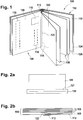
- FIG. 1 a book-shaped identification, value or security document 100 is shown.
- the identity document, value document or security document 100 is, for example, an identification document, in particular a passport or an identity card.
- the identification, value or security document 100 has a cover 102 and a passport book block 104 held in the cover 102.
- the passport book block 104 consists of a data card 106, a plurality of double pages 108, a cover sheet 110 and a lap band 112, which are connected to one another with a seam 114.
- the data card 106 is a plastic or paper-based card on which personal and / or document-specific information is applied.
- the data card 106 can have a passport picture 116 and personal information 118 of a user.
- the information 118 is preferably applied to the data card 106 in a machine-readable form.
- the data card 106 has a likewise machine-readable identification feature which the data card 106 uniquely identifies during the production process of the identification document, value document or security document 100.
- the data card 106 can furthermore have a chip in which personal and / or document-specific information can be stored.
- the chip has a secure memory area for storing personal and / or document-specific information.
- the data card 106 can have visible and / or invisible security features that prevent the data card 106 from being forged.
- a flexible tab 120 is provided on the data card 106 and is made from an endless belt.
- the tab 120 consists of a fabric that is coated and / or sheathed with a flexible plastic material.
- the tab 120 is attached to the data card 106 in a form-fitting and / or material fit and is thus part of the data card 106. Further security features can be provided on the tab 120.
- the double pages 108 are each cut from a sheet, preferably a sheet of paper, and folded along their center line 122.
- the double pages 108 can be printed, for example with person-specific and / or document-specific information, page numbers or other information.
- the double pages 108 can furthermore be prepared for the receipt of stamps, for example visa stamps.
- the double pages 108 also preferably contain security features which prevent the double pages 108 from being forged.
- the security features can, for example, be printed on, worked into double pages 108 or incorporated into them.
- the double sides 108 contain a perforation, the perforation tapering conically through the double sides 108.
- the cover sheet 110 forms the outer end of the passport book block 104. With the outside 124 of the cover sheet 110, the passport book block 104 is glued onto the inside 126 of the cover 102.
- the lap band 112 serves to reinforce the seam area and is glued to the outside 124 of the cover sheet 110 before the passport book block 104 is sewn.
- the cover 102 is made of a paper- and / or plastic-based material and can also have a chip.
- the data card 106 is provided and the tab 120 is attached to the data card ( Figure 2a ).
- the manufacture of the data card 106 is well known and will not be discussed in detail.
- the tab 120 is supplied as an endless strip, cut to the desired length and connected to the data card 106 in an overlapping area 121 in a form-fitting and / or material fit.
- the lap band 112 is applied to the seam area of the cover sheet 110 and the passport book block 104 consisting of the double pages 108, the data card 106 and the cover sheet 110 is put together ( Figure 2b ) and.
- the data card 106 is inserted into the passport book block 104 in such a way that the flap 120 is arranged in the seam area.
- the cover 102 is provided, the inside 126 is glued to the outside 124 of the cover sheet 110 and the passport blank 128 thus produced is folded ( Figures 2d and 2e ).
- the free edges of the passport book blank 128 are processed and the passport book blank 128 is cut to the final format of the ID, value or security document 100 ( Figure 2f ).
- the edges adjoining the spine and the edge of the passport book blank 128 or of the identity document, value or security document 100 opposite the spine are regarded as free edges.
- the system 150 has a device 200 for producing a data card 106 with a flexible tab 120 attached to it, a compiling device 300 for the passport book block 104, a device 400 for providing and attaching the lap band 112, a device 500 for collecting and Joining the double pages 108 of the front sheet 110, the lapping tape 112 and the flap 120 to a passport book block 104, a preparation device 600 for the cover, a gluing and folding device 700, a finishing device 800, a personalization device 850 and a transfer device 870.
- transport and holding devices 900, 1000 are provided to hold the data card 106, the cover sheet 110, the cover 102, the double pages 108, the passport book block 104, the passport book blank 128 and / or the ID, value or security document 100 between the Devices 200, 300, 400, 500, 600, 700, 800 to be transported individually.
- an acceptance device 250 for data cards is provided, which is part of the device 200 in the embodiment shown here.
- the acceptance device 250 can receive data cards 106 individually or in blocks, and can send them to further production in individual cases.
- a controller 152 is also provided, which is coupled to the devices 200, 250, 300, 400, 500, 600, 700, 800 and the transport and holding devices 900, 1000.
- FIG. 4 shows a flow chart of a method for producing an identity document, value document or security document (100).
- the data card (106) is manufactured with a tab (120).
- the corresponding double pages (108) (S02) and the corresponding front sheet (110) (S03) are then provided to each data card (106).
- the binding tape (112) is then attached to the front sheet (110) (S04).
- the data card (106) is then brought together with the double pages (108) and the cover sheet (110) (S05) and sewn to form a passport book block (104) (S06).
- the cover (102) is now provided (S07) and connected to the passport book block (104) to form a passport book blank (128) (S08).
- the passport book block (104) is finished (S09) and the chip is personalized (S10).
- the device 200 is designed to produce a data card 106 with a flexible tab 120 attached to it.
- the device 200 can accept a tabless data card 106 from the acceptance device 250 and attach a flexible tab 120 to the latter.
- the flap 120 is delivered, for example, as an endless belt 220 and cut to the desired length, the end regions of the endless belt being sealed in order to prevent fraying.
- the tab 120 is then attached to the data card 106 using an ultrasonic welding process. After the tab 120 has been attached, a quality control and an identification feature provided on the data card 106 are recorded.
- the identification feature is then transmitted to the controller 152 and the controller 152 accesses a parts list stored in a memory 154 and corresponding to the identification feature, which lists the number and type of double pages 108, possibly the type of cover sheet 110, the type of cover 102 and further production-specific features of the identification, value or security document 100 to be produced are defined.
- each data card 106 has an identification feature that uniquely identifies the data card 106.
- the identification feature can, however, also contain only a reference to a parts list or contain an assignment to a parts list without containing detailed information on the individual data card 106.
- the parts list can then be transmitted to the following devices 300, 400, 500, 600, 700, 800 as well as the transport and holding devices 900, 1000 on which the data card is located or the components for the identity card, value card assigned to the data card. or produce security document 100.
- the controller 152 is preferably designed in such a way that it can track the position of the data card 106 or the components of the ID, value or security document 100 assigned to the data card 106. For example, this can Identification feature of the data card 106 can be detected on the respective devices and transmitted to the controller 152. The controller 152 can then transmit the respective parts list or the necessary components for the production of the ID, value or security document 100 to the respective device 300, 400, 500, 600, 700, 800.
- the compilation device 300 can determine the number and type of double pages 108 as a function of the parts list that is determined after the identification feature has been recorded, provide them, personalize them and compile them in a desired sequence.
- the device 400 can provide a lap band 112 and attach it to a provided cover sheet 110 in the seam area.
- the personalized and provided double pages 108, the cover sheet 110 and the data card 106 are combined to form a passport book block 104 and connected to one another along the center line 122 with a seam 114.
- the supply device 600 for the cover provides the cover 102 as a function of the individual parts list and / or the identification feature and applies an adhesive layer 612 to the inside 126 of the cover 102.
- the cover 102 is connected to the passport book block 104 to form a passport book blank 128 and folded along the center line 122.
- the finishing device 800 can cut the folded passport book blank 128 to the final shape or format of the identification, value or security document 100.
- the personalization device 850 can incorporate individual features into the ID, value or security document 100, for example a laser perforation, or store person-specific and / or document-specific information in a chip of the ID, value or security document 100.
- the personalization device 850 has a unit 852 for unfolding the ID, value or security document 100, a unit 854 for making a laser perforation in the sides of the ID, value or security document 100, a unit 856 for closing the ID, valuable or security document 100 and a unit 858 for writing on the chip of ID, valuable or security document 100.
- the system is configured in such a way that the ID, value or security document 100 or its components are transferred directly between the devices 200, 300, 400, 500, 600, 700, 800, 850.
- transfer or buffer stations can also be provided between individual devices 200, 300, 400, 500, 600, 700, 800, 850.
- the transfer device 870 can collect the produced and personalized identification, value or security documents 100 and / or transfer them to a subsequent system for collecting and packaging.
- a holding and transport device 1000 with two ring-shaped guide units 1002 is provided, in each of which a holding receptacle 1006 is slidably mounted, so that an ID card inserted in the holding receptacle 1006 -, value or security document 100 can be transported between the units 852, 854, 856, 858 of the personalization device 850 and the transfer device 870.
- holding and transport devices 900 are provided which have a multi-articulated arm 902, which consists of a plurality of segments 904, each adjacent segments 904 being pivotable and / or rotatable relative to one another.
- the units 852, 854, 856, 858 of the personalization device 850 and the transfer device 870 are arranged in a ring to one another.
- the transport between the units 852, 854, 856, 858 of the personalization device 850 and the transfer device 870 takes place with the in FIG Figures 5a and 5b shown holding and transport device 1000.
- the holding and transport device 1000 has two ring-shaped guide units 1002 (see also Figure 6 ).
- Each guide unit 1002 defines an annular, closed path curve 1004, along which a holding receptacle 1006 mounted on the guide unit 1002 can be displaced.
- the planes of the trajectories 1004 run parallel to one another.
- Each guide unit 1002 has a drive 1008 in order to move the holding receptacle 1006 in each case along the trajectory 1004.
- the ring-shaped guide units 1002 are held on a common displacement arrangement 1010, which is formed by a plurality of rails 1012 arranged perpendicular to the plane of the ring-shaped guide units 1002.
- a drive 1014 for moving one of the guide units 1002 along the rails 1012 of the displacement arrangement 1010 is provided on the displacement arrangement 1010.
- An annular machining path 1016 is defined between the guide units 1002, the plane of which runs parallel to the planes of the trajectories of the guide units 1002 and which defines a toroidal or circular cylindrical machining region 1018.
- the guide units 1002 are each arranged on a first and a second side of the plane defined by the machining path.
- the guide units 1002 can each in a direction of movement 1020 running in the direction of the rails 1012 in a Figure 5c
- the directions of movement 1020 of the guide units 1002 are each directed in opposite directions and point away from the plane of the machining path.
- a control unit 1022 is provided to control the movement of the holding receptacles 1006 and the guide units 1002.
- the personalization devices 854, 856, 858 of the personalization device 852 and the finishing device 800 are arranged in such a way that they engage in the processing area and hold an identification, value or security document 100 held in a holding receptacle 1006, a passport blank 128, a passport book block 104 or a data card 106 can edit.
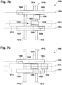
- a method for moving the holding receptacles 1006 is described below with reference to FIG Figures 7a to 7c explained.
- the control unit 1022 determines the trajectory 1024 of the first and / or the second holding receptacle 1006 in the machining position of the guide units 1002 of the holding receptacle 1006 or the first and / or the second holding receptacle 1006, in which the holding receptacles 1006 engage in the machining area 1016 ( Figure 7a ).
- the movement path 1024 can run between one of the personalization devices 854, 856, 858 of the personalization device 852 and the finishing device 800 or between the personalization device 852 or the finishing device 800 and the acceptance device 250 or the transfer device 870.
- the first and / or the second holding receptacle 1006 are then moved in the guide unit along the trajectory until the crossover area in the direction of movement of the holding receptacle 1006 is behind the first and / or the second holding receptacle 1006 and the guide unit 1002 is the first and / or the second Retainer 1006 moved back into the machining position ( Figure 7c ).
- the first and / or the second holding receptacle are moved along the movement paths 1024 in the processing position of the guide unit 1002 of the first and second holding receptacles 1006.
- a crossover area 1026 is identified, one or both holding receptacles 1006 are evaded by moving the guide unit 1002 of this holding receptacle 1006 into the evading position. This movement takes place independently of the movement of the holding receptacles 1006 along the guide units 1002, so that the evasive action does not result in a time delay.
- a second movement path of the first and / or the second holding receptacle (1006) can be determined in the opposite direction of movement and a check whether there is a crossover area on the second movement path, and then a comparison of the two trajectories as well as a selection of one of the trajectories. The selection can be made, for example, as a function of the time required for the respective movement path or in such a way that in each case a movement path is preferred in which no movement of the holding receptacle 1006 out of the processing area 1018 is necessary.
- the holding seat 1006 is moved out of the processing area 1018 by moving the guide units.
- the holding receptacle 1006 can also be movably, in particular pivotably, mounted on the guide unit 1002 and the holding receptacle 1006 is moved out of the processing area 1018 by pivoting the holding receptacle 1006 into an evasive position.
- Both embodiments can also be combined so that the holding receptacles 1006 can be pivoted and the guide units 1002 can be moved at the same time.
- the movement of the guide units 1002 and the holding receptacles 1006 from the machining position into the evasive position can also take place in other ways, as long as it is ensured that the holding receptacles 1006 are in the evasive position outside the machining area.
- crossover area 1026 If a crossover area 1026 is identified, only one holding receptacle 1006 can be pivoted out of the processing area 1018. It is also possible, however, for both holding receptacles 1006 to be pivoted.
- the holding receptacles 1006 are preferably designed in such a way that the identification, value or security document 100, the passport book blank 128, the passport book block 104 or the data card 106 can be processed in the holding receptacle 1006.
- the holding receptacles 1006 have, for example, two holding surfaces 1028, 1030 that are perpendicular to one another (see FIG Figure 8 ).
- the first holding surfaces 1028 are perpendicular to the plane defined by the machining path 1014
- the second holding surfaces 1030 are arranged parallel to the plane defined by the machining path and run in the machining position in particular in this plane.
- Locking means 1032, 1034 for an identification, value or security document 100, a passport book blank 128 or a book half of an identification, value or security document 100 are provided on both holding surfaces 1028, 1030.
- the first locking means 1032 have locking means, in particular locking levers 1036, which can automatically lock an ID, value or security document 100, a passport book blank 128 or a book half of an ID, value or security document 100 when it is inserted. Means for releasing the locking levers 1036 are preferably provided.
- the second locking means 1034 have clamping elements 1038, the clamping elements 1038 in the embodiment shown here each being able to engage on an edge of the ID, value or security document 100, the passport book blank 128 or the book half of an ID, value or security document 100.
- a device for unfolding the ID, value or security document 100, the passport book blank 128 or the passport book block 104 can be provided on each of the holding receptacles.
- the holding and transport device 1000 is assigned to the finishing device 800 and the personalization device 852.
- the holding receptacles 1006 an arrangement between further processing devices is also possible.
- the transport between two processing devices takes place in each case in the manner described according to the invention.
- the trajectories 1004 and the machining path 1014 can also have other shapes, as long as it is ensured that the holding receptacles 1006 are in the machining position within the machining area.
- the trajectories 1004 and the machining path each do not have to run in one plane.
Landscapes
- Credit Cards Or The Like (AREA)
Claims (15)
- Dispositif de maintien et de transport (1000), notamment pour la fabrication d'un document d'identité, de valeur ou de sécurité (100) sous forme de livret, dans lequel le document d'identité, de valeur ou de sécurité (100) présente une reliure (102), ainsi qu'un bloc passeport (104) comprenant une carte de données (106), plusieurs pages doubles (108), une page de garde (110) et une bande d'onglets (112), où la carte de données (106) présente une languette (120) souple reliée avec la carte de données (106) sur un bord, où la carte de données (106) avec la languette (120) souple, les doubles pages (108), la page de garde (110) et la bande d'onglets (112) sont cousues ensemble avec une couture (114), et où la reliure (102) avec une page intérieure (126) est collée à plat avec une page extérieure (124) de la page de garde (110), où l'ensemble de maintien et de transport (1000) présente :- au moins deux unités de guidage (1002),- au moins deux réceptacles de maintien (1006) pour respectivement un document d'identité, de valeur ou de sécurité (100), une ébauche de passeport (128), un bloc de livret de passeport (104), une reliure (102), une carte de données (106) ou une moitié de livret d'un document d'identité, de valeur ou de sécurité (100), et- une unité de commande (1022),dans lequel les réceptacles de maintien (1006) peuvent se déplacer respectivement dans une unité de guidage (1002), où les unités de guidage (1002) forment respectivement une trajectoire courbe (1004) fermée, le long de laquelle le réceptacle de maintien (1006) peut respectivement se déplacer,
dans lequel les unités de guidage (1002) et/ou les réceptacles de maintien (1006) peuvent se déplacer entre une position de traitement et une position de contournement,
dans lequel, dans une position de traitement des unités de guidage (1002) et/ou des réceptacles de maintien (1006), les réceptacles de maintien (1006) peuvent respectivement se déplacer le long de la trajectoire courbe (1004) dans une zone de traitement (1018) s'étendant le long d'une trajectoire de traitement (1016) fermée, dans lequel, dans la position de contournement des unités de guidage (1002) et/ou des réceptacles de maintien (1006), les réceptacles de maintien (1006) peuvent être déplacés respectivement à l'extérieur de la zone de traitement le long de la trajectoire courbe (1004),
dans lequel l'unité de commande (1022) est conçue pour la commande du déplacement des réceptacles de maintien (1006) le long des unités de guidage (1002) et pour la commande du déplacement des unités de guidage (1002) et/ou des réceptacles de maintien (1006) entre la position de traitement et la position de contournement,
dans lequel l'unité de commande (1022) est conçue pour la détermination d'une trajectoire de déplacement (1024) du premier et du deuxième réceptacle de maintien (1006), ainsi que pour la vérification si une zone de croisement (1026) des trajectoires de déplacement (1024) est présente le long des trajectoires de déplacement (1024),
où le déplacement des unités de guidage (1002) et/ou des réceptacles de maintien (1006) entre la position de traitement et la position de contournement a lieu en fonction du résultat de la vérification. - Dispositif de maintien et de transport selon la revendication 1, dans lequel la trajectoire de traitement (1016) est une trajectoire circulaire en forme d'anneau et la zone de traitement (1018) définit notamment une zone en cylindre creux ou en forme de tore autour de la trajectoire circulaire
ou
dans lequel la trajectoire de traitement (1016) est une trajectoire circulaire en forme d'anneau et la zone de traitement (1018) définit notamment une zone en cylindre creux ou en forme de tore autour de la trajectoire circulaire et les trajectoires courbes (1004) sont en forme d'anneaux, où les plans des trajectoires courbes (1004) sont disposées parallèlement au moins dans la position de traitement par rapport au plan de la trajectoire de traitement (1016). - Dispositif de maintien et de transport selon la revendication 2, dans lequel les directions de déplacement (1020), dans lesquelles les unités de guidage (1002) et/ou les réceptacles de maintien (1006) sont déplacés entre la position de traitement et la position de contournement, s'étendent perpendiculairement par rapport au plan de la trajectoire circulaire
ou
les directions de déplacement (1020), dans lesquelles les unités de guidage (1002) et/ou les réceptacles de maintien (1006) sont déplacés entre la position de traitement et la position de contournement, s'étendent perpendiculairement par rapport au plan de la trajectoire circulaire et les directions de déplacement (1020) des unités de guidage (1002) et/ou des réceptacles de maintien (1006) s'étendent dans des sens opposés entre la position de traitement et la position de contournement,
et/ou
les unités de guidage (1006) et/ou les réceptacles de maintien (1002) sont disposés sur des côtés opposés du plan de la trajectoire circulaire dans la position de contournement. - Dispositif de maintien et de transport selon l'une des revendications précédentes, dans lequel un système de décalage (1010) est prévu pour les unités de guidage (1002), où le système de décalage (1010) présente au moins un rail (1012) sur lequel les unités de guidage (1002) sont logées en pouvant être déplacées, ainsi qu'au moins un entraînement (1014) pour le déplacement des unités de guidage (1002) entre la position de traitement et la position de contournement et/ou
les réceptacles de maintien (1006) sont respectivement logés avec un système de pivotement ou de déplacement au niveau des unités de guidage (1002). - Dispositif de maintien et de transport selon l'une des revendications précédentes, dans lequel les réceptacles de maintien (1006) présentent deux surfaces de maintien (1028, 1030) se tenant perpendiculaires l'une à l'autre, où des moyens de verrouillage (1032, 1034) pour un document d'identité, de valeur ou de sécurité (100), une ébauche de passeport (128), un bloc de livret de passeport (104), une reliure (102), une carte de données (106) ou une moitié d'un document d'identité, de valeur ou de sécurité (100) sont prévus au niveau de la première et de la deuxième surface de maintien (1028, 1030).
- Dispositif de maintien et de transport selon la revendication 5, dans lequel le première surface de maintien (1028) est disposée perpendiculairement par rapport à un plan défini par la trajectoire de traitement (1016) dans la position de traitement et la deuxième surface de maintien (1030) est disposée parallèlement par rapport à un plan défini par la trajectoire de traitement (1016) dans la position de traitement, est disposée notamment dans le plan de la trajectoire de traitement (1016) et/ou
les moyens de verrouillage (1034) présentent des éléments de serrage (1038) et/ou
les moyens de verrouillage (1032) présentent des moyens de butée, notamment un levier de butée (1036). - Dispositif de maintien et de transport selon l'une des revendications précédentes, dans lequel un dispositif pour le pliage du document d'identité, de valeur ou de sécurité (100), de l'ébauche de passeport (128) ou du bloc de livret de passeport (104) est prévu respectivement au niveau des réceptacles de maintien (1006).
- Système (150) de production d'un document d'identité, de valeur ou de sécurité (100) en forme de livret, où le document d'identité, de valeur ou de sécurité (100) présente une reliure (102) ainsi qu'un bloc de livret de passeport (104) comprenant une carte de données (106), plusieurs doubles pages (108), une page de garde (110) et une bande d'onglets (112), où la carte de données (106) présente une languette (120) souple reliée le long d'un bord avec la carte de données, où la carte de données (106) avec la languette (120) souple, les doubles pages (108), la page de garde (110) et la bande d'onglet (112) sont cousues ensemble avec une couture (114), et où la reliure (102) avec une page intérieure (126) est collée à plat avec une page extérieure (124) de la page de garde (110), où le système (150) présente :- au moins un dispositif de traitement,- un dispositif d'admission,- un dispositif de transmission et- un dispositif de maintien et de transport (1000) selon l'une des revendications précédentes,dans lequel le dispositif de traitement prélève un élément dans la trajectoire de traitement (1016) et peut traiter un document d'identité, de valeur ou de sécurité (100), une ébauche de passeport (128), un bloc de livret de passeport (104), une reliure (102), une carte de données (106) ou une moitié de livret d'un document d'identité, de valeur ou de sécurité (100) dans un réceptacle de maintien (1006),
dans lequel les réceptacles de maintien (1006) sont conçus de telle manière que le dispositif de traitement puisse traiter un document d'identité, de valeur ou de sécurité (100), une ébauche de passeport (128), un bloc de livret de passeport (104), une reliure (102), une carte de données (106) ou une moitié de livret d'un document d'identité, de valeur ou de sécurité (100) maintenus dans un réceptacle de maintien. - Système selon la revendication 8, dans lequel le dispositif de traitement est un dispositif de vérification, un dispositif (200) permettant la mise en place d'une languette (120) sur une carte de données (106), un dispositif d'assemblage (300) pour un bloc de livret de passeport (104), un dispositif (400) permettant la mise en place d'une bande d'onglets (112) sur un bloc de livret de passeport (104), un dispositif de couture (500) pour un bloc de livret de passeport (104), un dispositif de collage et de pliage (700) pour une ébauche de passeport (128), un dispositif de façonnage final '800) pour une ébauche de passeport (128) ou un dispositif (852) pour la personnalisation d'un document d'identité, de valeur ou de sécurité (100).
- Procédé de mise en oeuvre d'un dispositif de maintien et de transport (1000) selon l'une des revendications 1 à 7, avec les étapes suivantes :a) la détermination d'une trajectoire de déplacement (1024) du premier et/ou du deuxième réceptacle de maintien (1006) dans la position de traitement de l'unité de guidage (1002) du réceptacle de maintien (1006) et/ou du premier, et/ou du deuxième réceptacle de maintien (1006),b) la vérification si, le long de la trajectoire de déplacement (1024) du premier et du deuxième réceptacle de maintien (1006), une zone de croisement (1026) est présente avec la trajectoire de déplacement (1024) de l'autre réceptacle de maintien (1006) respectif, en ce que les trajectoires de déplacement (1024) des réceptacles de maintien (1006) se touchent ou se superposent dans la zone de traitement (1018),c) le déplacement du premier et/ou du deuxième réceptacle de maintien (1006) le long de la trajectoire de déplacement,d) dans le cas où une zone de croisement (1026) des trajectoires de déplacement (1006) est présente avant d'avoir atteint la zone de croisement (1026), le déplacement du premier et/ou du deuxième réceptacle de maintien (1006) et/ou de l'unité de guidage (1002) du premier et/ou du deuxième réceptacle de maintien (1006) et/ou de l'unité de guidage (1002) du premier et/ou du deuxième réceptacle de maintien (1006) dans la position de contournement,e) le déplacement du premier et/ou du deuxième réceptacle de maintien (1006) dans l'unité de guidage (1002) jusqu'à ce que la zone de croisement (1026) dans la direction de déplacement du premier et ou du deuxième réceptacle de maintien (1006 se trouve derrière le premier et/ou le deuxième réceptacle de maintien (1006),f) le déplacement postérieur du premier et/ou du deuxième réceptacle de maintien (1006) et/ou de l'unité de guidage (1002) du premier et/ou du deuxième réceptacle de maintien (1006) dans la position de traitement, oug) dans le cas où aucune zone de croisement (1026) des trajectoires de déplacement (1024) n'est présente, le déplacement du premier et/ou du deuxième réceptacle de maintien (1006) le long des trajectoires de déplacement (1024) dans la position de traitement de l'unité de guidage (1002) du premier et/ou du deuxième réceptacle de maintien (1006), et/ou du premier et/ou du deuxième réceptacle de maintien (1006).
- Procédé selon la revendication 10, dans lequel des dispositifs de traitement sont prévus le long de la trajectoire de traitement (1016), et les dispositifs de maintien (1006) sont déplacés le long de la trajectoire de déplacement (1024) entre les dispositifs de traitement
ou
dans lequel des dispositifs de traitement sont prévus le long de la trajectoire de traitement (1016), et les dispositifs de maintien (1006) sont déplacés le long de la trajectoire de déplacement (1024) entre les dispositifs de traitement et après l'étape b), il y a une détermination d'une deuxième trajectoire de déplacement du premier et/ou du deuxième réceptacle de maintien (1006) dans le sens de déplacement opposé et une vérification s'il se présente une zone de croisement (1026) sur la deuxième trajectoire de déplacement et ensuite il y a une comparaison des deux trajectoires de déplacement ainsi qu'une sélection d'une des trajectoires de déplacement
ou
dans lequel des dispositifs de traitement sont prévus le long de la trajectoire de traitement (1016), et les dispositifs de maintien (1006) sont déplacés le long de la trajectoire de déplacement (1024) entre les dispositifs de traitement et après l'étape b), il y a une détermination d'une deuxième trajectoire de déplacement du premier et/ou du deuxième réceptacle de maintien (1006) dans le sens de déplacement opposé et une vérification s'il se présente une zone de croisement (1026) sur la deuxième trajectoire de déplacement et ensuite il y a une comparaison des deux trajectoires de déplacement ainsi qu'une sélection d'une des trajectoires de déplacement et la sélection a lieu en fonction du temps nécessaire pour la trajectoire de déplacement (1024) respective. - Procédé de production d'un document d'identité, de valeur ou de sécurité (100) avec un système selon l'une des revendications 8 ou 9, où le procédé présente les étapes suivantes :a) la mise à disposition du document d'identité, de valeur ou de sécurité (100), de l'ébauche de passeport (128), du bloc de livret de passeport (104), de la reliure (102), de la carte de données (106) ou de la moitié de livret d'un document d'identité, de valeur ou de sécurité (100) sur le dispositif de réception au niveau du dispositif d'admission,b) le déplacement du réceptacle de maintien (1006) vers le dispositif d'admission avec un procédé selon l'une des revendications 10 ou 11,c) la réception du document d'identité, de valeur ou de sécurité (100), de l'ébauche de passeport (128), du bloc de livret de passeport (104), de la reliure (102), de la carte de données (106) ou de la moitié de livret d'un document d'identité, de valeur ou de sécurité (100) avec le réceptacle de maintien,d) la détermination d'un dispositif de traitement pour le traitement du document d'identité, de valeur ou de sécurité (100), de l'ébauche de passeport (128), du bloc de livret de passeport (104), de la reliure (102), de la carte de données (106) ou de la moitié de livret d'un document d'identité, de valeur ou de sécurité (100),e) le déplacement du réceptacle de maintien (1006) vers le dispositif de traitement avec un procédé selon l'une des revendications 10 ou 11,f) le traitement du document d'identité, de valeur ou de sécurité (100), de l'ébauche de passeport (128), du bloc de livret de passeport (104), de la reliure (102), de la carte de données (106) ou de la moitié de livret d'un document d'identité, de valeur ou de sécurité (100) par le dispositif de traitement dans le réceptacle de maintien (1006),g) éventuellement, la répétition des étapes d) à f),h) le déplacement du réceptacle de maintien (1006) vers le dispositif de transmission avec un procédé selon l'une des revendications 10 ou 11,i) la transmission du document d'identité, de valeur ou de sécurité (100), de l'ébauche de passeport (128), du bloc de livret de passeport (104), de la reliure (102), de la carte de données (106) ou de la moitié de livret d'un document d'identité, de valeur ou de sécurité (100) au dispositif de transmission.
- Procédé selon l'une des revendications 11 à 12, dans lequel il y a un traitement des bords libres du document d'identité, de valeur ou de sécurité (100) au niveau d'un dispositif de traitement, notamment avec un procédé créant des copeaux, en particulier, avec un procédé de fraisage.
- Procédé selon l'une des revendications 11 à 13, dans lequel il y a une personnalisation du document d'identité, de valeur ou de sécurité (100), de l'ébauche de passeport (128), du bloc de livret de passeport (104), de la reliure (102), de la carte de données (106) ou de la moitié de livret d'un document d'identité, de valeur ou de sécurité (100) dans un dispositif de traitement.
- Procédé selon la revendication 14, dans lequel la personnalisation comprend un traitement physique du document d'identité, de valeur ou de sécurité (100), de l'ébauche de passeport (128), du bloc de livret de passeport (104), de la reliure (102), de la carte de données (106) ou de la moitié de livret d'un document d'identité, de valeur ou de sécurité (100), notamment une perforation par laser ou une impression ou
dans lequel la personnalisation comprend un traitement physique du document d'identité, de valeur ou de sécurité (100), de l'ébauche de passeport (128), du bloc de livret de passeport (104), de la reliure (102), de la carte de données (106) ou de la moitié de livret d'un document d'identité, de valeur ou de sécurité (100), notamment une perforation par laser ou une impression et la personnalisation comprend le stockage d'informations spécifiques de la personne et/ou du document dans une puce du document d'identité, de valeur ou de sécurité (100).
Applications Claiming Priority (2)
| Application Number | Priority Date | Filing Date | Title |
|---|---|---|---|
| DE102016218048.7A DE102016218048A1 (de) | 2016-09-20 | 2016-09-20 | Halte- und Transportvorrichtung, Verfahren zum Betrieb einer Halte- und Transportvorrichtung, System und Verfahren zur Herstellung eines buchförmigen Ausweis-, Wert- oder Sicherheitsdokuments |
| PCT/EP2017/073744 WO2018054956A1 (fr) | 2016-09-20 | 2017-09-20 | Dispositif de maintien et de transport, procédé pour faire fonctionner un dispositif de maintien et de transport, système et procédé de fabrication d'un document d'identité, de valeur ou infalsifiable en forme de livre |
Publications (2)
| Publication Number | Publication Date |
|---|---|
| EP3515718A1 EP3515718A1 (fr) | 2019-07-31 |
| EP3515718B1 true EP3515718B1 (fr) | 2020-11-25 |
Family
ID=59914480
Family Applications (1)
| Application Number | Title | Priority Date | Filing Date |
|---|---|---|---|
| EP17769081.5A Active EP3515718B1 (fr) | 2016-09-20 | 2017-09-20 | Dispositif de maintien et de transport, procédé pour faire fonctionner un dispositif de maintien et de transport, système et procédé de fabrication d'un document d'identité, de valeur ou infalsifiable en forme de livre |
Country Status (3)
| Country | Link |
|---|---|
| EP (1) | EP3515718B1 (fr) |
| DE (1) | DE102016218048A1 (fr) |
| WO (1) | WO2018054956A1 (fr) |
Family Cites Families (5)
| Publication number | Priority date | Publication date | Assignee | Title |
|---|---|---|---|---|
| US4827425A (en) | 1986-10-31 | 1989-05-02 | Thorn Emi Malco, Incorporated | System for personalization of integrated circuit microchip cards |
| DE19641892A1 (de) | 1996-10-10 | 1998-04-16 | Ods Gmbh & Co Kg | Vorrichtung sowie Verfahren zum Programmieren von Mikroprozessorkarten |
| DE102006042957B4 (de) | 2006-09-13 | 2010-01-21 | Böwe Cardtec GmbH | Vorrichtung und Verfahren zum Handhaben von Objekten |
| EP2457738B1 (fr) * | 2008-04-30 | 2015-02-11 | Müller Martini Holding AG | Procédé de reliure par collage d'un bloc de livre avec feuille de garde |
| DE102015202995A1 (de) | 2015-02-19 | 2016-08-25 | Bundesdruckerei Gmbh | Anlage und Verfahren zum Produzieren von buchförmig ausgestalteten Identifikationsdokumenten sowie Verfahren zum Errichten der Produktionsanlage |
-
2016
- 2016-09-20 DE DE102016218048.7A patent/DE102016218048A1/de not_active Withdrawn
-
2017
- 2017-09-20 EP EP17769081.5A patent/EP3515718B1/fr active Active
- 2017-09-20 WO PCT/EP2017/073744 patent/WO2018054956A1/fr unknown
Non-Patent Citations (1)
| Title |
|---|
| None * |
Also Published As
| Publication number | Publication date |
|---|---|
| EP3515718A1 (fr) | 2019-07-31 |
| DE102016218048A1 (de) | 2018-03-22 |
| WO2018054956A1 (fr) | 2018-03-29 |
Similar Documents
| Publication | Publication Date | Title |
|---|---|---|
| EP3515724B1 (fr) | Procédé, dispositifs et système de production d'un document d'identité, de valeur ou de sécurité se présentant sous la forme d'un livret | |
| EP3515719B1 (fr) | Système et procédé permettant de produire un document d'identité, de valeur ou de sécurité en forme de livret | |
| EP3515723B1 (fr) | Procédé, dispositif et système permettant de produire un document d'identité, de valeur ou de sécurité en forme de livret | |
| EP3515722B1 (fr) | Dispositif et procédé pour fabriquer une carte de données pour un document d'identité, document de valeur ou document de sécurité sous forme de livret, système et procédé pour fabriquer un document d'identité, document de valeur ou document de sécurité sous forme de livret et carte de données pour un document d'identité, document de valeur ou document de sécurité sous forme de livret | |
| EP3515721B1 (fr) | Dispositif et procédé de séparation et de tri de pages doubles pour document d'identité, de valeur ou de sécurité en forme de livre, procédé et système de fabrication d'un document d'identité, de valeur ou de sécurité en forme de livre | |
| EP3515718B1 (fr) | Dispositif de maintien et de transport, procédé pour faire fonctionner un dispositif de maintien et de transport, système et procédé de fabrication d'un document d'identité, de valeur ou infalsifiable en forme de livre | |
| EP3509863B1 (fr) | Système compact de fabrication d'un document d'identification, de valeur ou de sécurité | |
| EP3515717B1 (fr) | Dispositif de regroupement et procédé permettant de séparer et de trier des doubles pages | |
| DE102018103625A1 (de) | System zur herstellung und bearbeitung eines buchförmigen ausweis-, wert- oder sicherheitsdokuments und herstellverfahren | |
| DE102018106126B4 (de) | Herstellung eines buchförmigen Ausweis-, Wert- oder Sicherheitsdokumentes mittels Fräsens | |
| EP3515720B1 (fr) | Système et procédé pour produire un document d'identité, de valeur ou de sécurité se présentant sous la forme d'un livret, et document d'identité, de valeur ou de sécurité se présentant sous la forme d'un livret | |
| EP3515725B1 (fr) | Procédé et dispositif de fabrication d'un bloc de livret pour document d'identité, de valeur ou de sécurité en forme de livre, système de fabrication d'un document d'identité, de valeur ou de sécurité en forme de livre et document d'identité, de valeur ou de sécurité en forme de livre | |
| EP3509862B1 (fr) | Dispositif d'assemblage compact permettant de produire un carnet de feuilles de matériau | |
| DE102016217043B4 (de) | Kompakte Zusammentragvorrichtung zum Erstellen eines Materialbogenhefts | |
| EP1470930A2 (fr) | Publication imprimée et reliée comprenant deux jeux séparés de feuilles |
Legal Events
| Date | Code | Title | Description |
|---|---|---|---|
| STAA | Information on the status of an ep patent application or granted ep patent |
Free format text: STATUS: UNKNOWN |
|
| STAA | Information on the status of an ep patent application or granted ep patent |
Free format text: STATUS: THE INTERNATIONAL PUBLICATION HAS BEEN MADE |
|
| PUAI | Public reference made under article 153(3) epc to a published international application that has entered the european phase |
Free format text: ORIGINAL CODE: 0009012 |
|
| STAA | Information on the status of an ep patent application or granted ep patent |
Free format text: STATUS: REQUEST FOR EXAMINATION WAS MADE |
|
| 17P | Request for examination filed |
Effective date: 20190423 |
|
| AK | Designated contracting states |
Kind code of ref document: A1 Designated state(s): AL AT BE BG CH CY CZ DE DK EE ES FI FR GB GR HR HU IE IS IT LI LT LU LV MC MK MT NL NO PL PT RO RS SE SI SK SM TR |
|
| AX | Request for extension of the european patent |
Extension state: BA ME |
|
| DAV | Request for validation of the european patent (deleted) | ||
| DAX | Request for extension of the european patent (deleted) | ||
| GRAP | Despatch of communication of intention to grant a patent |
Free format text: ORIGINAL CODE: EPIDOSNIGR1 |
|
| STAA | Information on the status of an ep patent application or granted ep patent |
Free format text: STATUS: GRANT OF PATENT IS INTENDED |
|
| INTG | Intention to grant announced |
Effective date: 20200623 |
|
| GRAS | Grant fee paid |
Free format text: ORIGINAL CODE: EPIDOSNIGR3 |
|
| GRAA | (expected) grant |
Free format text: ORIGINAL CODE: 0009210 |
|
| STAA | Information on the status of an ep patent application or granted ep patent |
Free format text: STATUS: THE PATENT HAS BEEN GRANTED |
|
| AK | Designated contracting states |
Kind code of ref document: B1 Designated state(s): AL AT BE BG CH CY CZ DE DK EE ES FI FR GB GR HR HU IE IS IT LI LT LU LV MC MK MT NL NO PL PT RO RS SE SI SK SM TR |
|
| REG | Reference to a national code |
Ref country code: GB Ref legal event code: FG4D Free format text: NOT ENGLISH |
|
| REG | Reference to a national code |
Ref country code: CH Ref legal event code: EP |
|
| REG | Reference to a national code |
Ref country code: AT Ref legal event code: REF Ref document number: 1337857 Country of ref document: AT Kind code of ref document: T Effective date: 20201215 |
|
| REG | Reference to a national code |
Ref country code: DE Ref legal event code: R096 Ref document number: 502017008388 Country of ref document: DE |
|
| REG | Reference to a national code |
Ref country code: IE Ref legal event code: FG4D Free format text: LANGUAGE OF EP DOCUMENT: GERMAN |
|
| REG | Reference to a national code |
Ref country code: NL Ref legal event code: MP Effective date: 20201125 |
|
| PG25 | Lapsed in a contracting state [announced via postgrant information from national office to epo] |
Ref country code: RS Free format text: LAPSE BECAUSE OF FAILURE TO SUBMIT A TRANSLATION OF THE DESCRIPTION OR TO PAY THE FEE WITHIN THE PRESCRIBED TIME-LIMIT Effective date: 20201125 Ref country code: PT Free format text: LAPSE BECAUSE OF FAILURE TO SUBMIT A TRANSLATION OF THE DESCRIPTION OR TO PAY THE FEE WITHIN THE PRESCRIBED TIME-LIMIT Effective date: 20210325 Ref country code: NO Free format text: LAPSE BECAUSE OF FAILURE TO SUBMIT A TRANSLATION OF THE DESCRIPTION OR TO PAY THE FEE WITHIN THE PRESCRIBED TIME-LIMIT Effective date: 20210225 Ref country code: GR Free format text: LAPSE BECAUSE OF FAILURE TO SUBMIT A TRANSLATION OF THE DESCRIPTION OR TO PAY THE FEE WITHIN THE PRESCRIBED TIME-LIMIT Effective date: 20210226 Ref country code: FI Free format text: LAPSE BECAUSE OF FAILURE TO SUBMIT A TRANSLATION OF THE DESCRIPTION OR TO PAY THE FEE WITHIN THE PRESCRIBED TIME-LIMIT Effective date: 20201125 |
|
| PG25 | Lapsed in a contracting state [announced via postgrant information from national office to epo] |
Ref country code: PL Free format text: LAPSE BECAUSE OF FAILURE TO SUBMIT A TRANSLATION OF THE DESCRIPTION OR TO PAY THE FEE WITHIN THE PRESCRIBED TIME-LIMIT Effective date: 20201125 Ref country code: LV Free format text: LAPSE BECAUSE OF FAILURE TO SUBMIT A TRANSLATION OF THE DESCRIPTION OR TO PAY THE FEE WITHIN THE PRESCRIBED TIME-LIMIT Effective date: 20201125 Ref country code: IS Free format text: LAPSE BECAUSE OF FAILURE TO SUBMIT A TRANSLATION OF THE DESCRIPTION OR TO PAY THE FEE WITHIN THE PRESCRIBED TIME-LIMIT Effective date: 20210325 Ref country code: SE Free format text: LAPSE BECAUSE OF FAILURE TO SUBMIT A TRANSLATION OF THE DESCRIPTION OR TO PAY THE FEE WITHIN THE PRESCRIBED TIME-LIMIT Effective date: 20201125 Ref country code: BG Free format text: LAPSE BECAUSE OF FAILURE TO SUBMIT A TRANSLATION OF THE DESCRIPTION OR TO PAY THE FEE WITHIN THE PRESCRIBED TIME-LIMIT Effective date: 20210225 |
|
| REG | Reference to a national code |
Ref country code: LT Ref legal event code: MG9D |
|
| PG25 | Lapsed in a contracting state [announced via postgrant information from national office to epo] |
Ref country code: HR Free format text: LAPSE BECAUSE OF FAILURE TO SUBMIT A TRANSLATION OF THE DESCRIPTION OR TO PAY THE FEE WITHIN THE PRESCRIBED TIME-LIMIT Effective date: 20201125 |
|
| PG25 | Lapsed in a contracting state [announced via postgrant information from national office to epo] |
Ref country code: RO Free format text: LAPSE BECAUSE OF FAILURE TO SUBMIT A TRANSLATION OF THE DESCRIPTION OR TO PAY THE FEE WITHIN THE PRESCRIBED TIME-LIMIT Effective date: 20201125 Ref country code: SK Free format text: LAPSE BECAUSE OF FAILURE TO SUBMIT A TRANSLATION OF THE DESCRIPTION OR TO PAY THE FEE WITHIN THE PRESCRIBED TIME-LIMIT Effective date: 20201125 Ref country code: CZ Free format text: LAPSE BECAUSE OF FAILURE TO SUBMIT A TRANSLATION OF THE DESCRIPTION OR TO PAY THE FEE WITHIN THE PRESCRIBED TIME-LIMIT Effective date: 20201125 Ref country code: EE Free format text: LAPSE BECAUSE OF FAILURE TO SUBMIT A TRANSLATION OF THE DESCRIPTION OR TO PAY THE FEE WITHIN THE PRESCRIBED TIME-LIMIT Effective date: 20201125 Ref country code: LT Free format text: LAPSE BECAUSE OF FAILURE TO SUBMIT A TRANSLATION OF THE DESCRIPTION OR TO PAY THE FEE WITHIN THE PRESCRIBED TIME-LIMIT Effective date: 20201125 Ref country code: SM Free format text: LAPSE BECAUSE OF FAILURE TO SUBMIT A TRANSLATION OF THE DESCRIPTION OR TO PAY THE FEE WITHIN THE PRESCRIBED TIME-LIMIT Effective date: 20201125 |
|
| REG | Reference to a national code |
Ref country code: DE Ref legal event code: R097 Ref document number: 502017008388 Country of ref document: DE |
|
| PG25 | Lapsed in a contracting state [announced via postgrant information from national office to epo] |
Ref country code: DK Free format text: LAPSE BECAUSE OF FAILURE TO SUBMIT A TRANSLATION OF THE DESCRIPTION OR TO PAY THE FEE WITHIN THE PRESCRIBED TIME-LIMIT Effective date: 20201125 |
|
| PLBE | No opposition filed within time limit |
Free format text: ORIGINAL CODE: 0009261 |
|
| STAA | Information on the status of an ep patent application or granted ep patent |
Free format text: STATUS: NO OPPOSITION FILED WITHIN TIME LIMIT |
|
| PG25 | Lapsed in a contracting state [announced via postgrant information from national office to epo] |
Ref country code: AL Free format text: LAPSE BECAUSE OF FAILURE TO SUBMIT A TRANSLATION OF THE DESCRIPTION OR TO PAY THE FEE WITHIN THE PRESCRIBED TIME-LIMIT Effective date: 20201125 Ref country code: NL Free format text: LAPSE BECAUSE OF FAILURE TO SUBMIT A TRANSLATION OF THE DESCRIPTION OR TO PAY THE FEE WITHIN THE PRESCRIBED TIME-LIMIT Effective date: 20201125 Ref country code: IT Free format text: LAPSE BECAUSE OF FAILURE TO SUBMIT A TRANSLATION OF THE DESCRIPTION OR TO PAY THE FEE WITHIN THE PRESCRIBED TIME-LIMIT Effective date: 20201125 |
|
| 26N | No opposition filed |
Effective date: 20210826 |
|
| PG25 | Lapsed in a contracting state [announced via postgrant information from national office to epo] |
Ref country code: SI Free format text: LAPSE BECAUSE OF FAILURE TO SUBMIT A TRANSLATION OF THE DESCRIPTION OR TO PAY THE FEE WITHIN THE PRESCRIBED TIME-LIMIT Effective date: 20201125 |
|
| PG25 | Lapsed in a contracting state [announced via postgrant information from national office to epo] |
Ref country code: ES Free format text: LAPSE BECAUSE OF FAILURE TO SUBMIT A TRANSLATION OF THE DESCRIPTION OR TO PAY THE FEE WITHIN THE PRESCRIBED TIME-LIMIT Effective date: 20201125 |
|
| REG | Reference to a national code |
Ref country code: CH Ref legal event code: PL |
|
| REG | Reference to a national code |
Ref country code: BE Ref legal event code: MM Effective date: 20210930 |
|
| PG25 | Lapsed in a contracting state [announced via postgrant information from national office to epo] |
Ref country code: IS Free format text: LAPSE BECAUSE OF FAILURE TO SUBMIT A TRANSLATION OF THE DESCRIPTION OR TO PAY THE FEE WITHIN THE PRESCRIBED TIME-LIMIT Effective date: 20210325 Ref country code: MC Free format text: LAPSE BECAUSE OF FAILURE TO SUBMIT A TRANSLATION OF THE DESCRIPTION OR TO PAY THE FEE WITHIN THE PRESCRIBED TIME-LIMIT Effective date: 20201125 |
|
| PG25 | Lapsed in a contracting state [announced via postgrant information from national office to epo] |
Ref country code: LU Free format text: LAPSE BECAUSE OF NON-PAYMENT OF DUE FEES Effective date: 20210920 Ref country code: IE Free format text: LAPSE BECAUSE OF NON-PAYMENT OF DUE FEES Effective date: 20210920 Ref country code: BE Free format text: LAPSE BECAUSE OF NON-PAYMENT OF DUE FEES Effective date: 20210930 |
|
| PG25 | Lapsed in a contracting state [announced via postgrant information from national office to epo] |
Ref country code: LI Free format text: LAPSE BECAUSE OF NON-PAYMENT OF DUE FEES Effective date: 20210930 Ref country code: CH Free format text: LAPSE BECAUSE OF NON-PAYMENT OF DUE FEES Effective date: 20210930 |
|
| PG25 | Lapsed in a contracting state [announced via postgrant information from national office to epo] |
Ref country code: CY Free format text: LAPSE BECAUSE OF FAILURE TO SUBMIT A TRANSLATION OF THE DESCRIPTION OR TO PAY THE FEE WITHIN THE PRESCRIBED TIME-LIMIT Effective date: 20201125 |
|
| P01 | Opt-out of the competence of the unified patent court (upc) registered |
Effective date: 20230526 |
|
| PG25 | Lapsed in a contracting state [announced via postgrant information from national office to epo] |
Ref country code: HU Free format text: LAPSE BECAUSE OF FAILURE TO SUBMIT A TRANSLATION OF THE DESCRIPTION OR TO PAY THE FEE WITHIN THE PRESCRIBED TIME-LIMIT; INVALID AB INITIO Effective date: 20170920 |
|
| REG | Reference to a national code |
Ref country code: AT Ref legal event code: MM01 Ref document number: 1337857 Country of ref document: AT Kind code of ref document: T Effective date: 20220920 |
|
| PG25 | Lapsed in a contracting state [announced via postgrant information from national office to epo] |
Ref country code: AT Free format text: LAPSE BECAUSE OF NON-PAYMENT OF DUE FEES Effective date: 20220920 |
|
| PG25 | Lapsed in a contracting state [announced via postgrant information from national office to epo] |
Ref country code: MK Free format text: LAPSE BECAUSE OF FAILURE TO SUBMIT A TRANSLATION OF THE DESCRIPTION OR TO PAY THE FEE WITHIN THE PRESCRIBED TIME-LIMIT Effective date: 20201125 |
|
| PG25 | Lapsed in a contracting state [announced via postgrant information from national office to epo] |
Ref country code: TR Free format text: LAPSE BECAUSE OF FAILURE TO SUBMIT A TRANSLATION OF THE DESCRIPTION OR TO PAY THE FEE WITHIN THE PRESCRIBED TIME-LIMIT Effective date: 20201125 |
|
| PG25 | Lapsed in a contracting state [announced via postgrant information from national office to epo] |
Ref country code: MT Free format text: LAPSE BECAUSE OF FAILURE TO SUBMIT A TRANSLATION OF THE DESCRIPTION OR TO PAY THE FEE WITHIN THE PRESCRIBED TIME-LIMIT Effective date: 20201125 |
|
| PGFP | Annual fee paid to national office [announced via postgrant information from national office to epo] |
Ref country code: DE Payment date: 20240919 Year of fee payment: 8 |
|
| PGFP | Annual fee paid to national office [announced via postgrant information from national office to epo] |
Ref country code: GB Payment date: 20240923 Year of fee payment: 8 |
|
| PGFP | Annual fee paid to national office [announced via postgrant information from national office to epo] |
Ref country code: FR Payment date: 20240924 Year of fee payment: 8 |