EP3514085A1 - Transport- und zuführeinheit für vorformlinge - Google Patents
Transport- und zuführeinheit für vorformlinge Download PDFInfo
- Publication number
- EP3514085A1 EP3514085A1 EP18152394.5A EP18152394A EP3514085A1 EP 3514085 A1 EP3514085 A1 EP 3514085A1 EP 18152394 A EP18152394 A EP 18152394A EP 3514085 A1 EP3514085 A1 EP 3514085A1
- Authority
- EP
- European Patent Office
- Prior art keywords
- conveyor belt
- preforms
- transport
- feed unit
- sensor
- Prior art date
- Legal status (The legal status is an assumption and is not a legal conclusion. Google has not performed a legal analysis and makes no representation as to the accuracy of the status listed.)
- Granted
Links
- 238000011144 upstream manufacturing Methods 0.000 claims abstract description 20
- 230000004888 barrier function Effects 0.000 claims description 10
- 238000000071 blow moulding Methods 0.000 description 5
- 230000007246 mechanism Effects 0.000 description 3
- 239000013590 bulk material Substances 0.000 description 2
- 239000012535 impurity Substances 0.000 description 2
- 238000012432 intermediate storage Methods 0.000 description 2
- 230000001105 regulatory effect Effects 0.000 description 2
- 238000005096 rolling process Methods 0.000 description 2
- 238000009827 uniform distribution Methods 0.000 description 2
- 230000005540 biological transmission Effects 0.000 description 1
- 238000009826 distribution Methods 0.000 description 1
- 238000007689 inspection Methods 0.000 description 1
- 238000009434 installation Methods 0.000 description 1
- 238000000926 separation method Methods 0.000 description 1
- 239000012815 thermoplastic material Substances 0.000 description 1
- 230000007704 transition Effects 0.000 description 1
Images

Classifications
-
- B—PERFORMING OPERATIONS; TRANSPORTING
- B65—CONVEYING; PACKING; STORING; HANDLING THIN OR FILAMENTARY MATERIAL
- B65G—TRANSPORT OR STORAGE DEVICES, e.g. CONVEYORS FOR LOADING OR TIPPING, SHOP CONVEYOR SYSTEMS OR PNEUMATIC TUBE CONVEYORS
- B65G43/00—Control devices, e.g. for safety, warning or fault-correcting
- B65G43/08—Control devices operated by article or material being fed, conveyed or discharged
-
- B—PERFORMING OPERATIONS; TRANSPORTING
- B29—WORKING OF PLASTICS; WORKING OF SUBSTANCES IN A PLASTIC STATE IN GENERAL
- B29C—SHAPING OR JOINING OF PLASTICS; SHAPING OF MATERIAL IN A PLASTIC STATE, NOT OTHERWISE PROVIDED FOR; AFTER-TREATMENT OF THE SHAPED PRODUCTS, e.g. REPAIRING
- B29C49/00—Blow-moulding, i.e. blowing a preform or parison to a desired shape within a mould; Apparatus therefor
- B29C49/42—Component parts, details or accessories; Auxiliary operations
- B29C49/4205—Handling means, e.g. transfer, loading or discharging means
-
- B—PERFORMING OPERATIONS; TRANSPORTING
- B29—WORKING OF PLASTICS; WORKING OF SUBSTANCES IN A PLASTIC STATE IN GENERAL
- B29C—SHAPING OR JOINING OF PLASTICS; SHAPING OF MATERIAL IN A PLASTIC STATE, NOT OTHERWISE PROVIDED FOR; AFTER-TREATMENT OF THE SHAPED PRODUCTS, e.g. REPAIRING
- B29C31/00—Handling, e.g. feeding of the material to be shaped, storage of plastics material before moulding; Automation, i.e. automated handling lines in plastics processing plants, e.g. using manipulators or robots
- B29C31/008—Handling preformed parts, e.g. inserts
-
- B—PERFORMING OPERATIONS; TRANSPORTING
- B29—WORKING OF PLASTICS; WORKING OF SUBSTANCES IN A PLASTIC STATE IN GENERAL
- B29C—SHAPING OR JOINING OF PLASTICS; SHAPING OF MATERIAL IN A PLASTIC STATE, NOT OTHERWISE PROVIDED FOR; AFTER-TREATMENT OF THE SHAPED PRODUCTS, e.g. REPAIRING
- B29C49/00—Blow-moulding, i.e. blowing a preform or parison to a desired shape within a mould; Apparatus therefor
- B29C49/02—Combined blow-moulding and manufacture of the preform or the parison
- B29C49/06—Injection blow-moulding
-
- B—PERFORMING OPERATIONS; TRANSPORTING
- B65—CONVEYING; PACKING; STORING; HANDLING THIN OR FILAMENTARY MATERIAL
- B65G—TRANSPORT OR STORAGE DEVICES, e.g. CONVEYORS FOR LOADING OR TIPPING, SHOP CONVEYOR SYSTEMS OR PNEUMATIC TUBE CONVEYORS
- B65G47/00—Article or material-handling devices associated with conveyors; Methods employing such devices
- B65G47/34—Devices for discharging articles or materials from conveyor
- B65G47/46—Devices for discharging articles or materials from conveyor and distributing, e.g. automatically, to desired points
- B65G47/51—Devices for discharging articles or materials from conveyor and distributing, e.g. automatically, to desired points according to unprogrammed signals, e.g. influenced by supply situation at destination
- B65G47/5104—Devices for discharging articles or materials from conveyor and distributing, e.g. automatically, to desired points according to unprogrammed signals, e.g. influenced by supply situation at destination for articles
-
- B—PERFORMING OPERATIONS; TRANSPORTING
- B65—CONVEYING; PACKING; STORING; HANDLING THIN OR FILAMENTARY MATERIAL
- B65G—TRANSPORT OR STORAGE DEVICES, e.g. CONVEYORS FOR LOADING OR TIPPING, SHOP CONVEYOR SYSTEMS OR PNEUMATIC TUBE CONVEYORS
- B65G47/00—Article or material-handling devices associated with conveyors; Methods employing such devices
- B65G47/52—Devices for transferring articles or materials between conveyors i.e. discharging or feeding devices
- B65G47/68—Devices for transferring articles or materials between conveyors i.e. discharging or feeding devices adapted to receive articles arriving in one layer from one conveyor lane and to transfer them in individual layers to more than one conveyor lane or to one broader conveyor lane, or vice versa, e.g. combining the flows of articles conveyed by more than one conveyor
- B65G47/682—Devices for transferring articles or materials between conveyors i.e. discharging or feeding devices adapted to receive articles arriving in one layer from one conveyor lane and to transfer them in individual layers to more than one conveyor lane or to one broader conveyor lane, or vice versa, e.g. combining the flows of articles conveyed by more than one conveyor from a single conveyor lane consisting of one conveyor or several adjacent conveyors
-
- B—PERFORMING OPERATIONS; TRANSPORTING
- B29—WORKING OF PLASTICS; WORKING OF SUBSTANCES IN A PLASTIC STATE IN GENERAL
- B29C—SHAPING OR JOINING OF PLASTICS; SHAPING OF MATERIAL IN A PLASTIC STATE, NOT OTHERWISE PROVIDED FOR; AFTER-TREATMENT OF THE SHAPED PRODUCTS, e.g. REPAIRING
- B29C49/00—Blow-moulding, i.e. blowing a preform or parison to a desired shape within a mould; Apparatus therefor
- B29C49/02—Combined blow-moulding and manufacture of the preform or the parison
- B29C2049/023—Combined blow-moulding and manufacture of the preform or the parison using inherent heat of the preform, i.e. 1 step blow moulding
-
- B—PERFORMING OPERATIONS; TRANSPORTING
- B29—WORKING OF PLASTICS; WORKING OF SUBSTANCES IN A PLASTIC STATE IN GENERAL
- B29K—INDEXING SCHEME ASSOCIATED WITH SUBCLASSES B29B, B29C OR B29D, RELATING TO MOULDING MATERIALS OR TO MATERIALS FOR MOULDS, REINFORCEMENTS, FILLERS OR PREFORMED PARTS, e.g. INSERTS
- B29K2105/00—Condition, form or state of moulded material or of the material to be shaped
- B29K2105/25—Solid
- B29K2105/253—Preform
-
- B—PERFORMING OPERATIONS; TRANSPORTING
- B65—CONVEYING; PACKING; STORING; HANDLING THIN OR FILAMENTARY MATERIAL
- B65G—TRANSPORT OR STORAGE DEVICES, e.g. CONVEYORS FOR LOADING OR TIPPING, SHOP CONVEYOR SYSTEMS OR PNEUMATIC TUBE CONVEYORS
- B65G2201/00—Indexing codes relating to handling devices, e.g. conveyors, characterised by the type of product or load being conveyed or handled
- B65G2201/02—Articles
- B65G2201/0235—Containers
- B65G2201/0244—Bottles
-
- B—PERFORMING OPERATIONS; TRANSPORTING
- B65—CONVEYING; PACKING; STORING; HANDLING THIN OR FILAMENTARY MATERIAL
- B65G—TRANSPORT OR STORAGE DEVICES, e.g. CONVEYORS FOR LOADING OR TIPPING, SHOP CONVEYOR SYSTEMS OR PNEUMATIC TUBE CONVEYORS
- B65G2203/00—Indexing code relating to control or detection of the articles or the load carriers during conveying
- B65G2203/04—Detection means
- B65G2203/042—Sensors
- B65G2203/044—Optical
Definitions
- the invention relates to a transport and feed unit for preforms, in particular for PET bottles, wherein the transport and feed unit can be fed with preforms at its upstream end and feeds the preforms to a conveyor unit arranged at the downstream end of the transport and feed unit.
- U1 is a device for supplying preforms or preforms made of thermoplastic material with a support ring in the region of the open end to a blow molding machine for producing hollow bodies, with a ground-mounted silo for disorderly receiving multiple preforms, one of the preforms in one with the open end up-facing position-aligning and single-row forming sorters, a slant conveyor moving the preforms randomly from the silo to the roller sorter, and having a downwardly inclined slide supporting the support rings, which receives a plurality of open-ended upwardly facing preforms in a row and feeds them by means of downdraft of the blow molding machine, wherein the roller sorter is placed close to the ground and between the roller sorter and the elevated upper end of the chute, a preform raising elevator is turned on.
- the silo is periodically filled from above, by means of a corresponding tilting device by pouring supplied in boxes preforms.
- a disadvantage of this solution is that the preforms can be damaged or scratched by the bulk material or the impact in the silo and that in this case a very high noise level is generated.
- a device for feeding a conveyor system with a large amount of parts, such as preforms or hollow bodies comprises a tilting device with a pivotable tilting part and a device for intermediate storage of the parts, wherein the device for intermediate storage is a silo with a liftable cover and the tilting device has a mechanical connection and force transmission element which is connected to the liftable cover of the silo , Even with this solution, it may be due to the bulk material to damage / scratches on the preforms and to an increased noise level.
- a transport and feed unit for preforms in particular for PET bottles, specified, which is fed at its upstream end with preforms and the preforms of a arranged at the downstream end of the transport and feed unit conveyor unit feeding, wherein the transport and feed unit comprises a first conveyor belt and a second conveyor belt, wherein at the downstream end of the first conveyor belt a funnel-like device is provided, through which the preforms arrive on the second conveyor belt, which are the preforms of the arranged at its downstream end conveyor unit supplies.
- This solution is particularly suitable for high transport speeds (i.e., over 50,000 preforms per hour). However, it is relatively complex and costly.
- a transport and feed unit for preforms for preforms, in particular for PET bottles, wherein the transport and feed unit can be fed with preforms at its upstream end and supplies the preforms to a conveyor unit arranged at the downstream end of the transport and feed unit, wherein the transport and feed unit comprises a first conveyor belt and a second conveyor belt, the second conveyor belt being disposed at the downstream end of the first conveyor belt, the first conveyor belt feeding the preforms to the second conveyor belt, the second conveyor belt holding the preforms at its downstream end arranged feed unit supplies and wherein in the upstream end region (ie in the inlet) of the second conveyor belt, a distance sensor is arranged.
- the conveyor unit is presently not part of the claimed transport and feed unit.
- the first conveyor belt and the second conveyor belt are arranged at right angles to each other. On This way, a space-saving installation can be achieved.
- a bevel is arranged at the downstream end of the first conveyor belt, over which slide the preforms on the second conveyor belt.
- the slope is intended to ensure the smoothest possible transition of the preforms from the first to the second conveyor belt and for a good distribution of the preforms on the second conveyor belt.
- the slope also includes a dirt separation, preferably in the form of slots, so that dirt or impurities can not get onto the second conveyor belt.
- the slope extends at least over the entire width of the first conveyor belt and more preferably approximately to the middle of the second conveyor belt.
- a uniform distribution of the preforms on the second conveyor belt is achieved lengthwise and preferably one, optional and variable, narrowing or narrowing of the second conveyor belt.
- the distance sensor can be displaced laterally along the rear wall of the second conveyor belt.
- a first sensor (preferably in the form of a light barrier) is arranged in the upstream end region of the first conveyor belt. If the first sensor or the first light barrier no preforms detected more, the tilting device moves back to its original or loading position to receive a new box or a new batch of preforms.
- a second sensor (preferably in the form of a light barrier) is arranged between the first sensor and the downstream end region of the first conveyor belt. If the second sensor or the second light barrier does not detect any preforms, the tilting device regularly provided for feeding the first conveyor belt can again move into the pouring position and tilt a new batch of preforms onto the belt without the risk of backlogging or rolling back of Preforms is given.
- the first conveyor belt always moves at its normal transport speed.
- the tilting device is presently not part of the claimed transport and feed unit.
- a third sensor (preferably in the form of a light barrier) is arranged in the downstream end region of the first conveyor belt. If the third sensor detects no preforms in its area, the first conveyor belt is driven to drive faster to deliver preforms from behind.
- the (adjustable) distance sensor monitors when the second conveyor belt is free of preforms over the width of the first conveyor belt (possibly also approximately to the level of the downstream end of the slope). As long as this is not the case no further preforms are delivered to the second conveyor belt by the first conveyor belt. That is, when the third sensor detects preforms in its area and the distance sensor (still) preforms in the range of the width of the first conveyor belt (possibly also before the downstream end of the slope) detected on the second conveyor belt, the first conveyor belt is stopped.
- the first conveyor belt is restarted to deliver preforms. This is to prevent heaps or that subsequent preforms fall on the other preforms and scratch them and thereby additionally generate noise.
- the preform carpet on the first conveyor is thus controlled by the speed.
- the drive of the first conveyor belt insofar comprises a start-stop mechanism.
- a further sensor is arranged in the region of the downstream end of the slope. With this sensor, the speed of the second conveyor belt can be controlled. When the sensor is free (i.e., when it detects no preforms in its area), the speed of the second conveyor is increased, such as via a frequency converter.
- the other sensor should preferably be mounted near the transfer to the backpack silo, so that no preforms are "shot" into the backpack silo when switching to fast operation.
- the frequency converter setting may be selected to provide fast, slow, or consistent belt speed.
- the sensors are configured as light barriers. This form of sensors has proven to be particularly reliable and efficient for the underlying application. All sensors are otherwise connected to a conventional control.
- the first conveyor belt is fed via a tilting device arranged at its upstream end. This has proved to be advantageous in connection with the described speed control of the first conveyor belt.
- the second conveyor belt brings the preforms into a buffer device, preferably designed as a backpack silo, which is connected upstream of the conveyor unit.
- This buffer device ensures that the conveyor unit or the high-level conveyor can continue to supply preforms to downstream units if a correspondingly large gap arises on the second (and possibly also the first) conveyor belt.
- the backpack silo or the buffer device has a maximum level sensor with preforms. If the maximum level is reached, the second conveyor belt and possibly also the first conveyor belt is stopped.
- the backpack silo or the buffer device can additionally also have a minimum sensor. When the minimum level is reached, the second and possibly also the first conveyor belt is driven at a higher speed.
- the first conveyor belt is designed as a soft belt. In this way, damage and / or scratches of the preforms are avoided when pouring onto the first conveyor belt and it can be additionally reduced noise.
- the second (transverse) conveyor belt can be designed as a soft band accordingly.
- the first conveyor belt has a length between 2000 mm and 3000 mm, preferably between 2250 mm and 2750 mm. Further preferably, the first conveyor belt has a width of 1500 mm to 3500 mm, preferably from 2000 mm to 3000 mm.
- the second conveyor belt has a length between 2000 mm and 5000 mm, preferably between 2500 mm and 4000 mm. Further preferably, the second conveyor belt has a width of 200 mm to 1000 mm, preferably from 200 to 500 mm.
- first conveyor belt By using the sensors described above or the corresponding control / regulating mechanism, in particular a relatively short first conveyor belt can be used. Above all, it is not necessary to provide an additional (longitudinal) conveyor belt adjoining the first conveyor belt in order to sufficiently pull apart the quantity of preforms in front of the second (transverse) conveyor belt with a view to continuous operation as far as possible.
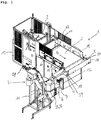
- Fig. 1 an arrangement consisting of an inventive transport and feed unit 1 with upstream tilting device 2 and downstream high conveyor 7 is illustrated. Such an arrangement is regularly part of a conveyor system with which preforms are transferred to a stretch blow molding machine.
- the tilting device 2 is charged with preforms (for example with a cardboard box full of preforms), which are then tilted onto the first conveyor belt 3 of the transport and feed unit 1 according to the invention.
- preforms for example with a cardboard box full of preforms
- the first conveyor belt 3 brings the preforms up to the slope 5, via which the preforms reach the second conveyor belt 4.
- the slope 5 comprises a dirt deposit, preferably in the form of slots, so that dirt or impurities can not reach the second conveyor belt 4.
- the preforms are preferably placed in a buffer device, here in the form of a backpack silo 6. The preforms then enter the conveyor unit or the high-level conveyor 7 via the backpack silo.
- the stretch blow molding machine can also be preceded by an inspection and ejection unit, in which the preforms are separated and checked for possible damage and, if necessary, sorted out.
- the area of the transport and feed unit 1 according to the invention with the grid parts 14 placed on the side walls 15 and the backstop 17 at the upstream end of the first conveyor belt 3 should cooperate with the tilting device 2 such that no preforms are formed when the first conveyor belt 3 is loaded with the preforms fall down laterally or remain at the interface between the tilting device 2 and the first conveyor belt 3 or roll back.
- the tilting device 2 is arranged in a frame 13 and is driven by a drive 18.
- the height of fall of the preforms of the tilting device 2 on the first conveyor belt 3, which is regularly formed as a soft belt, in the inventive transport and feeding device 1 is preferably less than 100 mm, so that the preforms carry by the bulking no damage / scratches off and the Noise level can be kept low.
- the preforms are brought to the slope 5 in the transport direction T1 by means of the first conveyor belt 3.
- the first conveyor belt 3 is driven by a drive 10 and supported by a frame 12.
- covers can also be provided above the first conveyor belt 3.
- a slope 5 is provided, which ensures that the preforms arrive as smoothly as possible on the second conveyor belt 4.
- the second conveyor belt 4 brings the preforms to the backpack silo 6, which is upstream of the high conveyor 7.
- the high conveyor is supported by a frame 11.
- the senor S1 is arranged in the starting region of the first conveyor belt 3, the sensor S2 in the middle region of the first conveyor belt 3, and the sensor S3 in the end region of the first conveyor belt 3 (i.e., each above the first conveyor belt 3 in the side wall 15).
- the sensors S1, S2 and S3 are preferably designed as light barriers and connected to a conventional controller (not shown).
- the tilting device 2 is accordingly activated to drive to the loading or starting position in order to receive a new box or a new batch of preforms.
- the tilting device 2 If the first sensor S1 (or the first light barrier) no longer detects preforms in its area, the tilting device 2 returns to its original or loading position in order to be fitted with new preforms.
- a second sensor S2 is arranged between the first sensor S1 and the downstream end region of the first conveyor belt 3, a second sensor S2 is arranged.
- the tilting device 2 is driven back to the pouring position and a new batch of preforms is tilted onto the first conveyor belt 3, without the risk of backwater or a rolling back of preforms is given.
- the first conveyor belt 3 in this case always moves at its normal transport speed.
- a third sensor S3 is arranged in the downstream end region of the first conveyor belt 3. If the third sensor detects no preforms in its area, the first conveyor belt 3 is driven to drive faster to nachzuarrin from behind preforms.
- the adjustable distance sensor SD scans the preforms on the second conveyor belt 4 and thus monitors when the second conveyor belt 4 over the width B1 of the first conveyor belt 3 (possibly also up to approximately the level of the downstream end of the slope 5, ie the lateral bevel 5a ) is free of preforms. As long as this is not the case, no further preforms are delivered to the second conveyor belt 4 by the first conveyor belt 3.
- the first conveyor belt 3 is restarted to deliver preforms.
- the preform carpet on the first conveyor belt 3 is thus controlled by the speed.
- the drive 10 of the first conveyor belt insofar comprises a start-stop mechanism.
- a further sensor S4 is preferably arranged in the region of the downstream end of the bevel 5.
- the speed of the second conveyor belt 4 can be regulated.
- the speed of the second conveyor 4 is increased.
- the speed of the second conveyor 4 is lowered. In this way, an optimally uniform regulation of the preform amount can be ensured without loss of time.
- the (further) sensor S4 should preferably be mounted near the transfer to the backpack silo 6, so that no preforms are "injected” into the backpack silo 6 when switching over to fast operation.
- the Frequency converter setting may be selected so that a fast, slow or constant belt speed is possible.
- the bevel 5 extends at least over the entire width B1 of the first conveyor belt 3 and more preferably approximately to the middle or to half of the width B2 of the second conveyor belt 4.
- the distance sensor SD can in this regard, depending on the preform size laterally along the rear wall 19 are added.
- the rear wall 19 is preferably designed to be folded down in order to be able to serve the same in a reversing operation of the second conveyor belt 4 for emptying.
- the slope 5 usually has a length which is slightly larger than the width B1 of the first conveyor belt 3, since the slope 5 at its downstream end still has a lateral bevel 5a, from which the preforms T2 slipping obliquely forward to ensure a smoother movement of the preform carpet on the second conveyor belt 4.
- the length L1 of the first conveyor belt 3 is between 2000 mm and 3000 mm, preferably between 2250 mm and 2750 mm.
- the width B1 of the first conveyor belt 3 is between 1500 mm and 3500 mm, preferably between 2000 mm and 3000 mm.
- the length L2 of the second conveyor belt 4 is between 2000 mm and 5000 mm, preferably between 2500 mm and 4000 mm.
- the width B2 of the second conveyor belt 4 is between 200 mm and 1000 mm, preferably between 200 and 500 mm.
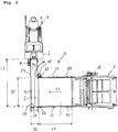
- Fig. 3 can be seen again in the side view, the arrangement of the sensor S4 in the side wall 16 of the second conveyor belt 4 and the arrangement of the maximum sensor S5 and the minimum sensor S6 in the side wall of the backpack silo. 6
- the backpack silo 6 functions as a buffer device and ensures that the high-level conveyor 7 can continue to supply preforms to downstream units if a correspondingly large gap arises on the first or second conveyor belt.
- the backpack silo 6 has at least one maximum sensor S5 for the filling level with preforms. If the maximum level is reached, the second conveyor belt 4 and possibly also the first conveyor belt 3 is stopped. If the maximum sensor S5 is free, it will continue to be conveyed.
- the backpack silo 6 may optionally have a minimum sensor S6. When the minimum level is reached, the second and possibly also the first conveyor belt 3, 4 are driven at a higher speed, so that the high-level conveyor 7 can be supplied as continuously as possible with preforms.
Abstract
Description
- Die Erfindung betrifft eine Transport- und Zuführeinheit für Vorformlinge, insbesondere für PET-Flaschen, wobei die Transport- und Zuführeinheit an ihrem stromaufwärtigen Ende mit Vorformlingen beschickbar ist und die Vorformlinge einer am stromabwärtigen Ende der Transport- und Zuführeinheit angeordneten Fördereinheit zuführt.
- Aus der
DE 203 08 513 U1 ist eine Vorrichtung zum Zuführen von Vorformlingen bzw. Preforms aus thermoplastischem Kunststoff mit einem Tragring im Bereich des offenen Endes zu einer Blasmaschine zum Herstellen von Hohlkörpern bekannt, mit einem bodennah aufgestellten Silo zur ungeordneten Aufnahme mehrerer Vorformlinge, einem die Vorformlinge in eine mit dem offenen Ende nach oben weisende Position ausrichtenden und zu einer Einzelreihe formierenden Rollensortierer, einem die Vorformlinge ungeordnet vom Silo zum Rollensortierer bewegenden Schrägförderer und mit einer abwärts geneigten, unter den Tragringen angreifende Tragschienen aufweisenden Rutsche, die mehrere mit dem offenen Ende nach oben weisende Vorformlinge in einer Reihe aufnimmt und diese mittels Hangabtrieb der Blasmaschine zuführt, wobei der Rollensortierer bodennah aufgestellt ist und zwischen den Rollensortierer und das erhöhte obere Ende der Rutsche ein die Vorformlinge anhebender Höhenförderer eingeschaltet ist. Bei dieser Vorrichtung wird das Silo von oben her, mittels einer entsprechenden Kippvorrichtung, durch Einschütten von in Kästen angelieferten Vorformlingen periodisch befüllt. - Nachteilig an dieser Lösung ist, dass die Vorformlinge durch den Schüttvorgang bzw. den Aufprall im Silo beschädigt bzw. verkratzt werden können und dass hierbei ein sehr hoher Lärmpegel erzeugt wird.
- In der
WO 2012/126129 A1 wird eine Vorrichtung zum Beschicken einer Förderanlage mit einer grossen Menge von Teilen, wie etwa Vorformlingen bzw. Preforms für Hohlkörper, beschrieben. Die Vorrichtung umfasst dabei eine Kippvorrichtung mit einem schwenkbaren Kipperteil und eine Vorrichtung zur Zwischenspeicherung der Teile, wobei die Vorrichtung zur Zwischenspeicherung ein Silo mit einer abhebbaren Abdeckung ist und die Kippvorrichtung ein mechanisches Verbindungs- und Kraftübertragungselement aufweist, welches mit der abhebbaren Abdeckung des Silos verbunden ist. Auch bei dieser Lösung kann es durch den Schüttvorgang zu Beschädigungen/Kratzern an den Vorformlingen kommen sowie zu einem erhöhten Lärmpegel. - In der
EP 17189934.7 - Diese Lösung ist insbesondere für hohe Transportgeschwindigkeiten (d.h. bei über 50'000 Vorformlingen pro Stunde) geeignet. Allerdings ist sie relativ komplex und kostenaufwändig.
- Es ist daher die Aufgabe der vorliegenden Erfindung, insbesondere für Anwendungen mit niedrigeren Transportgeschwindigkeiten eine weniger komplexe und kostengünstigere Lösung bereitzustellen, welche jedoch praktisch dieselben Vorteile bietet.
- Diese Aufgabe wird erfindungsgemäss gelöst durch eine Transport- und Zuführeinheit für Vorformlinge, insbesondere für PET-Flaschen, wobei die Transport- und Zuführeinheit an ihrem stromaufwärtigen Ende mit Vorformlingen beschickbar ist und die Vorformlinge einer am stromabwärtigen Ende der Transport- und Zuführeinheit angeordneten Fördereinheit zuführt, wobei die Transport- und Zuführeinheit ein erstes Transportband und ein zweites Transportband aufweist, wobei das zweite Transportband am stromabwärtigen Ende des ersten Transportbands angeordnet ist, wobei das erste Transportband die Vorformlinge dem zweiten Transportband zuführt, wobei das zweite Transportband die Vorformlinge der an seinem stromabwärtigen Ende angeordneten Fördereinheit zuführt und wobei im stromaufwärtigen Endbereich (d.h. im Einlauf) des zweiten Transportbands ein Distanzsensor angeordnet ist.
- Die Fördereinheit ist vorliegend nicht Teil der beanspruchten Transport- und Zuführeinheit.
- In einer bevorzugten Ausführungsform der vorliegenden Erfindung sind das erste Transportband und das zweite Transportband im rechten Winkel zueinander angeordnet. Auf diese Weise kann eine platzsparende Aufstellung erreicht werden.
- In einer weiteren bevorzugten Ausführungsform der vorliegenden Erfindung ist am stromabwärtigen Ende des ersten Transportbands eine Schräge angeordnet, über welche die Vorformlinge auf das zweite Transportband rutschen. Die Schräge soll für einen möglichst reibungslosen Übergang der Vorformlinge vom ersten auf das zweite Transportband sowie für eine gute Verteilung der Vorformlinge auf dem zweiten Transportband sorgen. Die Schräge umfasst zudem eine Schmutzabscheidung, vorzugsweise in Form von Schlitzen, damit Dreck bzw. Verunreinigungen nicht auf das zweite Transportband gelangen können.
- In einer weiteren bevorzugten Ausführungsform der vorliegenden Erfindung reicht die Schräge zumindest über die gesamte Breite des ersten Transportbands und weiter vorzugsweise etwa bis zur Mitte des zweiten Transportbands. Hierdurch wird einerseits eine gleichmässige Verteilung der Vorformlinge auf dem zweiten Transportband der Länge nach erreicht sowie vorzugsweise eine, optionale und variable, Verschmälerung bzw. Einengung des zweiten Transportbands. Der Distanzsensor kann diesbezüglich je nach Vorformlingsgrösse seitlich entlang der Rückwand des zweiten Transportbands versetzt werden.
- In einer weiteren bevorzugten Ausführungsform der vorliegenden Erfindung ist im stromaufwärtigen Endbereich des ersten Transportbands ein erster Sensor (vorzugsweise in Form einer Lichtschranke) angeordnet. Wenn der erste Sensor bzw. die erste Lichtschranke keine Vorformlinge mehr detektiert, fährt die Kippvorrichtung in ihre Ausgangs- bzw. Ladeposition zurück, um einen neuen Karton bzw. eine neue Charge mit Vorformlingen aufzunehmen.
- In einer weiteren bevorzugten Ausführungsform der vorliegenden Erfindung ist zwischen dem ersten Sensor und dem stromabwärtigen Endbereich des ersten Transportbands ein zweiter Sensor (vorzugsweise in Form einer Lichtschranke) angeordnet. Wenn der zweite Sensor bzw. die zweite Lichtschranke keine Vorformlinge detektiert, kann die zur Beschickung des ersten Transportbands regelmässig vorgesehene Kippvorrichtung wieder in die Schüttposition fahren und eine neue Charge von Vorformlingen auf das Band kippen, ohne dass die Gefahr eines Rückstaus bzw. eines Zurückrollens von Vorformlingen gegeben ist. Das erste Transportband fährt hierbei grundsätzlich mit seiner normalen Transportgeschwindigkeit. Die Kippvorrichtung ist vorliegend nicht Teil der beanspruchten Transport- und Zuführeinheit.
- In einer weiteren bevorzugten Ausführungsform der vorliegenden Erfindung ist im stromabwärtigen Endbereich des ersten Transportbands ein dritter Sensor (vorzugsweise in Form einer Lichtschranke) angeordnet. Wenn der dritte Sensor keine Vorformlinge in seinem Bereich detektiert, wird das erste Transportband angesteuert schneller zu fahren, um von hinten Vorformlinge nachzuliefern.
- In einer weiteren bevorzugten Ausführungsform der vorliegenden Erfindung überwacht der (einstellbare) Distanzsensor, wann das zweite Transportband über die Breite des ersten Transportbands (ggf. auch bis etwa in Höhe des stromabwärtig gelegenen Endes der Schräge) frei von Vorformlingen ist. Solange dies nicht der Fall ist, werden vom ersten Transportband keine weiteren Vorformlinge an das zweite Transportband geliefert. D.h., wenn der dritte Sensor Vorformlinge in seinem Bereich detektiert und der Distanzsensor (noch) Vorformlinge im Bereich der Breite des ersten Transportbands (ggf. auch vor dem stromabwärtig gelegenen Ende der Schräge) auf dem zweiten Transportband detektiert, wird das erste Transportband gestoppt.
- Erst wenn der Distanzsensor anzeigt, dass dieser Bereich frei von Vorformlingen ist (d.h. die Vorformlinge wurden in Transportrichtung am ersten Transportband bzw. am stromabwärtigen Ende der Schräge vorbeitransportiert), wird das erste Transportband wieder gestartet, um Vorformlinge nachzuliefern. Dies soll eine Haufenbildung verhindern bzw. dass nachrückende Vorformlinge auf die anderen Vorformlinge fallen und diese verkratzen und dabei zusätzlich Lärm erzeugen. Der Vorformlings-Teppich auf dem ersten Transportband wird also über die Geschwindigkeit gesteuert. Der Antrieb des ersten Transportbands umfasst insoweit einen Start-Stopp-Mechanismus.
- In einer weiteren bevorzugten Ausführungsform der vorliegenden Erfindung ist im Bereich des stromabwärtig gelegenen Endes der Schräge ein weiterer Sensor angeordnet. Mit diesem Sensor kann die Geschwindigkeit des zweiten Transportbands geregelt werden. Wenn der Sensor frei ist (d.h. wenn er keine Vorformlinge in seinem Bereich detektiert) wird die Geschwindigkeit des zweiten Transportbands etwa über einen Frequenzumrichter erhöht.
- Wenn der weitere Sensor belegt ist, wird die Geschwindigkeit des zweiten Transportbands herabgesetzt. Auf diese Weise kann eine optimal gleichmässige Regulierung der Vorformlingsmenge ohne Zeitverlust gewährleistet werden. Der weitere Sensor sollte vorzugsweise nahe der Übergabe zum Rucksacksilo montiert werden, damit bei einem Umschalten auf schnellen Betrieb keine Vorformlinge in das Rucksacksilo «eingeschossen» werden. Die Frequenzumrichter-Einstellung kann ggf. so gewählt werden, dass eine schnelle, langsame oder gleichbleibende Bandgeschwindigkeit möglich ist.
- In einer weiteren bevorzugten Ausführungsform der vorliegenden Erfindung sind die Sensoren (d.h. ausser dem Distanzsensor) als Lichtschranken ausgebildet. Diese Form der Sensoren hat sich für die hier zugrundeliegende Anwendung als besonders zuverlässig und effizient erwiesen. Alle Sensoren sind im Übrigen mit einer üblichen Steuerung verbunden.
- In einer weiteren bevorzugten Ausführungsform der vorliegenden Erfindung wird das erste Transportband über eine an seinem stromaufwärtigen Ende angeordnete Kippvorrichtung beschickt. Dies hat sich im Zusammenhang mit der beschriebenen Geschwindigkeits-Steuerung des ersten Transportbands als vorteilhaft erwiesen.
- In einer weiteren bevorzugten Ausführungsform der vorliegenden Erfindung bringt das zweite Transportband die Vorformlinge in eine vorzugsweise als Rucksacksilo ausgebildete Puffervorrichtung, welche der Fördereinheit vorgeschaltet ist, ein. Diese Puffervorrichtung sorgt dafür, dass die Fördereinheit bzw. der Hochförderer weiter Vorformlinge an nachgeordnete Einheiten liefern kann, wenn auf dem zweiten (und ggf. auch dem ersten) Transportband eine entsprechend grosse Lücke entsteht.
- Weiter vorzugsweise weist das Rucksacksilo bzw. die Puffervorrichtung jedenfalls einen Maximum-Sensor für den Füllstand mit Vorformlingen auf. Wird der Maximal-Füllstand erreicht, wird das zweite Transportband und ggf. auch das erste Transportband gestoppt. Das Rucksacksilo bzw. die Puffervorrichtung kann zudem auch noch einen Minimum-Sensor aufweisen. Wenn der minimale Füllstand erreicht wird, wird das zweite und ggf. auch das erste Transportband mit einer höheren Geschwindigkeit angesteuert.
- In einer weiteren bevorzugten Ausführungsform der vorliegenden Erfindung ist das erste Transportband als Softband ausgebildet. Auf diese Weise werden Beschädigungen und/oder Kratzer der Vorformlinge beim Schütten auf das erste Transportband vermieden und es kann zusätzlich Lärm vermindert werden. Auch das zweite (Quer-) Transportband kann entsprechend als Softband ausgebildet sein.
- In einer weiteren bevorzugten Ausführungsform der vorliegenden Erfindung weist das erste Transportband eine Länge zwischen 2000 mm und 3000 mm, vorzugsweise zwischen 2250 mm und 2750 mm, auf. Weiter vorzugsweise weist das erste Transportband eine Breite von 1500 mm bis 3500 mm, vorzugsweise von 2000 mm bis 3000 mm, auf.
- In einer weiteren bevorzugten Ausführungsform der vorliegenden Erfindung weist das zweite Transportband eine Länge zwischen 2000 mm und 5000 mm, vorzugsweise zwischen 2500 mm und 4000 mm, auf. Weiter vorzugsweise weist das zweite Transportband eine Breite von 200 mm bis 1000 mm, vorzugsweise von 200 bis 500 mm, auf.
- Durch die Verwendung der zuvor beschriebenen Sensoren bzw. dem entsprechenden Steuerungs-/Regelungsmechanismus kann insbesondere ein relativ kurzes erstes Transportband eingesetzt werden. Man braucht vor allem kein zusätzliches, sich an das erste Transportband anschliessendes, (Längs-) Transportband vorzusehen, um die Menge an Vorformlingen vor dem zweiten (Quer-) Transportband im Hinblick auf einen möglichst kontinuierlichen Betrieb ausreichend auseinanderzuziehen.
- In den beigefügten Zeichnungen sollen lediglich zum Zwecke der Anschaulichkeit beispielhafte Ausführungsformen der vorliegenden Erfindung illustriert werden.
- Es zeigt:
- Fig. 1
- eine perspektivische Ansicht einer Anordnung bestehend aus einer erfindungsgemässen Transport- und Zuführeinheit mit einer vorgeschalteten Kippvorrichtung und einem nachgeschalteten Hochförderer;
- Fig. 2
- eine Draufsicht auf die Anordnung mit der erfindungsgemässen Transport- und Zuführeinheit mit vorgeschalteter Kippvorrichtung und nachgeschaltetem Hochförderer gemäss
Fig. 1 ; - Fig. 3
- eine Seitenansicht der Anordnung mit der erfindungsgemässen Transport- und Zuführeinheit mit vorgeschalteter Kippvorrichtung und nachgeschaltetem Hochförderer gemäss
Fig. 1 . - In
Fig. 1 wird eine Anordnung bestehend aus einer erfindungsgemässen Transport- und Zuführeinheit 1 mit vorgeschalteter Kippvorrichtung 2 und nachgeschaltetem Hochförderer 7 illustriert. Eine derartige Anordnung ist regelmässig Teil einer Förderanlage mit welcher Vorformlinge in eine Streckblasmaschine überführt werden. - Dabei wird zunächst die Kippvorrichtung 2 mit Vorformlingen beschickt (z.B. mit einem Karton voller Vorformlinge), welche anschliessend auf das erste Transportband 3 der erfindungsgemässen Transport- und Zuführeinheit 1 gekippt werden.
- Das erste Transportband 3 bringt die Vorformlinge bis zu der Schräge 5, über welche die Vorformlinge auf das zweite Transportband 4 gelangen. Die Schräge 5 umfasst eine Schmutzabscheidung, vorzugsweise in Form von Schlitzen, damit Dreck bzw. Verunreinigungen nicht auf das zweite Transportband 4 gelangen können. Von dem zweiten Transportband 4 werden die Vorformlinge vorzugsweise in eine Puffervorrichtung, hier in Form eines Rucksacksilos 6, gebracht. Über das Rucksacksilo gelangen die Vorformlinge dann in die Fördereinheit bzw. den Hochförderer 7.
- An den Hochförderer 7 schliesst sich üblicherweise ein Rollensortierer (nicht gezeigt) an, in welchem die Vorformlinge aufrecht gestellt werden. Über eine Ablaufschiene gelangen die Vorformlinge schliesslich in eine Streckblasmaschine (nicht gezeigt). Der Streckblasmaschine kann allerdings auch eine Inspektions- und Auswerfereinheit vorgeschaltet sein, in welcher die Vorformlinge vereinzelt sowie auf mögliche Beschädigungen geprüft und ggf. aussortiert werden.
- Der Bereich der erfindungsgemässen Transport- und Zuführeinheit 1 mit den auf die Seitenwände 15 aufgesetzten Gitterteilen 14 sowie der Rücklaufsperre 17 am stromaufwärtigen Ende des ersten Transportbands 3 soll mit der Kippvorrichtung 2 dergestalt zusammenwirken, dass bei der Beschickung des ersten Transportbands 3 mit den Vorformlingen keine Vorformlinge seitlich herunterfallen oder an der Schnittstelle zwischen der Kippvorrichtung 2 und dem erstem Transportband 3 liegen bleiben bzw. zurückrollen. Die Kippvorrichtung 2 ist in einem Gestell 13 angeordnet und wird von einem Antrieb 18 angetrieben.
- Die Fallhöhe der Vorformlinge von der Kippvorrichtung 2 auf das erste Transportband 3, welches regelmässig als Softband ausgebildet ist, beträgt bei der erfindungsgemässen Transport- und Zuführvorrichtung 1 bevorzugt weniger als 100 mm, so dass die Vorformlinge durch den Schüttvorgang keine Beschädigungen/Kratzer davontragen und der Lärmpegel niedrig gehalten werden kann.
- Nach dem Schüttvorgang werden die Vorformlinge mittels des ersten Transportbands 3 in der Transportrichtung T1 zu der Schräge 5 gebracht. Das erste Transportband 3 wird dabei mittels eines Antriebs 10 angetrieben und von einem Gestell 12 getragen. Über dem ersten Transportband 3 können aus hygienischen Gründen auch Abdeckungen vorgesehen werden.
- An der Schnittstelle zwischen dem ersten Transportband 3 und dem zweiten Transportband 4 ist eine Schräge 5 vorgesehen, welche dafür sorgt, dass die Vorformlinge möglichst reibungslos auf das zweite Transportband 4 gelangen.
- Das zweite Transportband 4 bringt die Vorformlinge zu dem Rucksacksilo 6, welches dem Hochförderer 7 vorgeschaltet ist. Der Hochförderer wird von einem Gestell 11 getragen.
- Anhand von
Fig. 2 und3 wird nunmehr insbesondere die Anordnung der einzelnen Sensoren am ersten Transportband 3 (Sensoren S1, S2 und S3), am zweiten Transportband 4 (Sensoren SD und S4) sowie am Rucksacksilo 6 (Sensoren S5 und ggf. S6) beschrieben. - Wie zu sehen, ist der Sensor S1 im Anfangsbereich des ersten Transportbands 3 angeordnet, der Sensor S2 im mittleren Bereich des ersten Transportbands 3 und der Sensor S3 im Endbereich des ersten Transportbands 3 (d.h. jeweils oberhalb des ersten Transportbands 3 in der Seitenwand 15). Die Sensoren S1, S2 und S3 sind vorzugsweise als Lichtschranken ausgebildet und mit einer üblichen Steuerung (nicht gezeigt) verbunden.
- Wenn der Sensor S1 feststellt, dass im Anfangsbereich des ersten Transportbands 3 keine Vorformlinge vorhanden sind, wird entsprechend die Kippvorrichtung 2 angesteuert in die Lade- bzw. Ausgangsposition zu fahren, um einen neuen Karton bzw. eine neue Charge mit Vorformlingen aufzunehmen.
- Wenn der erste Sensor S1 (bzw. die erste Lichtschranke) keine Vorformlinge mehr in seinem Bereich detektiert, fährt die Kippvorrichtung 2 in ihre Ausgangs- bzw. Ladeposition zurück, um mit neuen Vorformlingen bestückt zu werden.
- Zwischen dem ersten Sensor S1 und dem stromabwärtigen Endbereich des ersten Transportbands 3 ist ein zweiter Sensor S2 angeordnet. Wenn der zweite Sensor S2 (bzw. die zweite Lichtschranke) keine Vorformlinge in ihrem Bereich detektiert, wird die Kippvorrichtung 2 wieder in die Schüttposition gefahren und eine neue Charge von Vorformlingen wird auf das erste Transportband 3 gekippt, ohne dass die Gefahr eines Rückstaus bzw. eines Zurückrollens von Vorformlingen gegeben ist. Das erste Transportband 3 fährt hierbei grundsätzlich mit seiner normalen Transportgeschwindigkeit.
- Des Weiteren ist im stromabwärtigen Endbereich des ersten Transportbands 3 ein dritter Sensor S3 angeordnet. Wenn der dritte Sensor keine Vorformlinge in seinem Bereich detektiert, wird das erste Transportband 3 angesteuert schneller zu fahren, um von hinten Vorformlinge nachzuliefern.
- In der Rückwand 19 des zweiten Transportbands 4 ist (stirnseitig) der einstellbare Distanzsensor SD angeordnet. Der Distanzsensor SD tastet die Vorformlinge auf dem zweiten Transportband 4 ab und überwacht so, wann das zweite Transportband 4 über die Breite B1 des ersten Transportbands 3 (ggf. auch bis etwa in Höhe des stromabwärtig gelegenen Endes der Schräge 5, d.h. der seitlichen Abschrägung 5a) frei von Vorformlingen ist. Solange dies nicht der Fall ist, werden vom ersten Transportband 3 keine weiteren Vorformlinge an das zweite Transportband 4 geliefert.
- Dies bedeutet, dass wenn der dritte Sensor S3 Vorformlinge in seinem Bereich detektiert und der Distanzsensor SD (noch) Vorformlinge in Transportrichtung T2 über die Breite B1 des ersten Transportbands 3 (ggf. auch vor dem stromabwärtig gelegenen Endes der Schräge 5) auf dem zweiten Transportband 4 detektiert, das erste Transportband 3 gestoppt wird.
- Erst wenn der Distanzsensor SD anzeigt, dass der entsprechende Bereich frei von Vorformlingen ist, wird das erste Transportband 3 wieder gestartet, um Vorformlinge nachzuliefern.
- Dies soll eine Haufenbildung verhindern bzw. dass nachrückende Vorformlinge auf die anderen Vorformlinge fallen und diese verkratzen und dabei zusätzlich Lärm erzeugen. Der Vorformlings-Teppich auf dem ersten Transportband 3 wird also über die Geschwindigkeit gesteuert. Der Antrieb 10 des ersten Transportbands umfasst insoweit einen Start-Stopp-Mechanismus.
- Im Bereich des stromabwärtig gelegenen Endes der Schräge 5 ist bevorzugt ein weiterer Sensor S4 angeordnet. Mit dem Sensor S4 kann die Geschwindigkeit des zweiten Transportbands 4 geregelt werden. Wenn der Sensor S4 frei ist (d.h. wenn er keine Vorformlinge in seinem Bereich detektiert) wird die Geschwindigkeit des zweiten Transportbands 4 erhöht.
- Wenn der Sensor S4 allerdings belegt ist (d.h. wenn er Vorformlinge in seinem Bereich detektiert), wird die Geschwindigkeit des zweiten Transportbands 4 herabgesetzt. Auf diese Weise kann eine optimal gleichmässige Regulierung der Vorformlingsmenge ohne Zeitverlust gewährleistet werden.
- Der (weitere) Sensor S4 sollte vorzugsweise nahe der Übergabe zum Rucksacksilo 6 montiert werden, damit bei einem Umschalten auf schnellen Betrieb keine Vorformlinge in das Rucksacksilo 6 «eingeschossen» werden. Die Frequenzumrichter-Einstellung kann ggf. so gewählt werden, dass eine schnelle, langsame oder gleichbleibende Bandgeschwindigkeit möglich ist.
- Wie weiterhin zu sehen, reicht die Schräge 5 zumindest über die gesamte Breite B1 des ersten Transportbands 3 und weiter vorzugsweise etwa bis zur Mitte bzw. bis zur Hälfte der Breite B2 des zweiten Transportbands 4. Hierdurch wird einerseits eine gleichmässige Verteilung der Vorformlinge auf dem zweiten Transportband 4 der Länge nach erreicht sowie vorzugsweise eine, optionale und variable, Verschmälerung bzw. Einengung des zweiten Transportbands 4. Der Distanzsensor SD kann diesbezüglich je nach Vorformlingsgrösse seitlich entlang der Rückwand 19 versetzt werden.
- Die Rückwand 19 ist vorzugsweise umklappbar ausgestaltet, um ggf. bei einem reversierenden Betrieb des zweiten Transportbands 4 zum Entleeren desselben dienen zu können.
- Die Schräge 5 weist in der Regel eine Länge auf, welche etwas grösser ist als die Breite B1 des ersten Transportbands 3, da die Schräge 5 an ihrem stromabwärtigen Ende noch eine seitliche Abschrägung 5a aufweist, von der die Vorformlinge T2 schräg nach vorne abrutschen, um eine flüssigere Bewegung des Vorformlingsteppichs auf dem zweiten Transportband 4 zu gewährleisten.
- Die Länge L1 des ersten Transportbands 3 liegt zwischen 2000 mm und 3000 mm, vorzugsweise zwischen 2250 mm und 2750 mm. Die Breite B1 des ersten Transportbands 3 liegt zwischen 1500 mm und 3500 mm, vorzugsweise zwischen 2000 mm und 3000 mm.
- Die Länge L2 des zweiten Transportbands 4 liegt zwischen 2000 mm und 5000 mm, vorzugsweise zwischen 2500 mm und 4000 mm. Die Breite B2 des zweiten Transportbands 4 liegt zwischen 200 mm und 1000 mm, vorzugsweise zwischen 200 und 500 mm.
- In
Fig. 3 erkennt man nochmals in der Seitenansicht die Anordnung des Sensors S4 in der Seitenwand 16 des zweiten Transportbands 4 sowie die Anordnung des Maximum-Sensors S5 und des Minimum-Sensors S6 in der Seitenwand des Rucksacksilos 6. - Das Rucksacksilo 6 fungiert vorliegend als Puffervorrichtung und sorgt dafür, dass der Hochförderer 7 weiter Vorformlinge an nachgeordnete Einheiten liefern kann, wenn auf dem ersten bzw. zweiten Transportband eine entsprechend grosse Lücke entsteht.
- Das Rucksacksilo 6 weist in diesem Zusammenhang zumindest einen Maximum-Sensor S5 für den Füllstand mit Vorformlingen auf. Wird der Maximal-Füllstand erreicht, wird das zweite Transportband 4 und ggf. auch das erste Transportband 3 gestoppt. Ist der Maximum-Sensor S5 frei, wird weitergefördert. Das Rucksacksilo 6 kann optional noch einen Minimum-Sensor S6 aufweisen. Wenn der minimale Füllstand erreicht wird, wird das zweite und ggf. auch das erste Transportband 3, 4 mit einer höheren Geschwindigkeit angesteuert, damit der Hochförderer 7 möglichst kontinuierlich mit Vorformlingen beliefert werden kann.
- Aus der
Fig. 3 erkennt man ausserdem noch die Anordnung des Antriebs 9 für das zweite Transportband 4 sowie des Antriebs 8 für den Hochförderer 7. -
- 1
- Transport- und Zuführeinheit
- 2
- Kippvorrichtung
- 3
- erstes Transportband
- 4
- zweites Transportband
- 5
- Schräge
- 5a
- seitliche Abschrägung
- 6
- Rucksacksilo (bzw. Puffervorrichtung)
- 7
- Hochförderer
- 8
- Antrieb Hochförderer
- 9
- Antrieb zweites Transportband
- 10
- Antrieb erstes Transportband
- 11
- Gestell Hochförderer
- 12
- Gestell erstes Transportband
- 13
- Gestell Kippvorrichtung
- 14
- Seitengitter
- 15
- Seitenwände (erstes Transportband)
- 16
- Seitenwände (zweites Transportband)
- 17
- Rücklaufsperre
- 18
- Antrieb Kippvorrichtung
- 19
- Rückwand zweites Transportband (umklappbar)
- L1
- Länge erstes Transportband
- B1
- Breite erstes Transportband
- L2
- Länge zweites Transportband
- B2
- Breite zweites Transportband
- S1
- Sensor erstes Transportband (Anfangsbereich)
- S2
- Sensor erstes Transportband (mittlerer Bereich)
- S3
- Sensor erstes Transportband (Endbereich)
- S4
- (weiterer) Sensor zweites Transportband
- S5
- Maximum-Sensor Rucksacksilo
- S6
- Minimum-Sensor Rucksacksilo (optional)
- SD
- Distanzsensor
- T1
- Transportrichtung erstes Transportband
- T2
- Transportrichtung zweites Transportband
Claims (15)
- Transport- und Zuführeinheit für Vorformlinge, insbesondere für PET-Flaschen, wobei die Transport- und Zuführeinheit (1) an ihrem stromaufwärtigen Ende mit Vorformlingen beschickbar ist und die Vorformlinge einer am stromabwärtigen Ende der Transport- und Zuführeinheit (1) angeordneten Fördereinheit (7) zuführt, wobei die Transport- und Zuführeinheit (1) ein erstes Transportband (3) und ein zweites Transportband (4) aufweist, dadurch gekennzeichnet, dass das zweite Transportband (4) am stromabwärtigen Ende des ersten Transportbands (3) angeordnet ist, wobei das erste Transportband (3) die Vorformlinge dem zweiten Transportband (4) zuführt, wobei das zweite Transportband (4) die Vorformlinge der an seinem stromabwärtigen Ende angeordneten Fördereinheit (7) zuführt und wobei im stromaufwärtigen Endbereich des zweiten Transportbands (4) ein Distanzsensor (SD) angeordnet ist.
- Transport- und Zuführeinheit nach Anspruch 1, dadurch gekennzeichnet, dass das erste Transportband (3) und das zweite Transportband (4) im rechten Winkel zueinander angeordnet sind.
- Transport- und Zuführeinheit nach Anspruch 1 oder 2, dadurch gekennzeichnet, dass am stromabwärtigen Ende des ersten Transportbands (3) eine Schräge (5) angeordnet ist, über welche die Vorformlinge auf das zweite Transportband (4) rutschen.
- Transport- und Zuführeinheit nach einem der vorhergehenden Ansprüche, dadurch gekennzeichnet, dass die Schräge (5) zumindest über die gesamte Breite (B) des ersten Transportbands (3) und vorzugsweise etwa bis zur Mitte des zweiten Transportbands (4) reicht.
- Transport- und Zuführeinheit nach einem der vorhergehenden Ansprüche, dadurch gekennzeichnet, dass im stromaufwärtigen Endbereich des ersten Transportbands (3) ein erster Sensor (S1) angeordnet ist.
- Transport- und Zuführeinheit nach einem der vorhergehenden Ansprüche, dadurch gekennzeichnet, dass zwischen dem ersten Sensor (S1) und dem stromabwärtigen Endbereich des ersten Transportbands (3) ein zweiter Sensor (S2) angeordnet ist.
- Transport- und Zuführeinheit nach einem der vorhergehenden Ansprüche, dadurch gekennzeichnet, dass im stromabwärtigen Endbereich des ersten Transportbands (3) ein dritter Sensor (S3) angeordnet ist.
- Transport- und Zuführeinheit nach einem der vorhergehenden Ansprüche, dadurch gekennzeichnet, dass der Distanzsensor (SD) überwacht, wann das zweite Transportband (4) über die Breite (B1) des ersten Transportbands (3) frei von Vorformlingen ist.
- Transport- und Zuführeinheit nach einem der vorhergehenden Ansprüche, dadurch gekennzeichnet, dass im Bereich des stromabwärtig gelegenen Endes der Schräge (5) ein weiterer Sensor (S4) angeordnet ist.
- Transport- und Zuführeinheit nach einem der vorhergehenden Ansprüche, dadurch gekennzeichnet, dass die Sensoren (S1), (S2), (S3), (S4), (S5) und ggf. (S6) als Lichtschranken ausgebildet sind.
- Transport- und Zuführeinheit nach einem der vorhergehenden Ansprüche, dadurch gekennzeichnet, dass das erste Transportband (3) über eine an seinem stromaufwärtigen Ende angeordnete Kippvorrichtung (2) beschickt wird.
- Transport- und Zuführeinheit nach einem der vorhergehenden Ansprüche, dadurch gekennzeichnet, dass das zweite Transportband (4) die Vorformlinge in eine vorzugsweise als Rucksacksilo ausgebildete Puffervorrichtung (6), welche der Fördereinheit (7) vorgeschaltet ist, einbringt.
- Transport- und Zuführeinheit nach einem der vorhergehenden Ansprüche, dadurch gekennzeichnet, dass das erste Transportband (3) als Softband ausgebildet ist.
- Transport- und Zuführeinheit nach einem der vorhergehenden Ansprüche, dadurch gekennzeichnet, dass das zweite Transportband (4) als Softband ausgebildet ist.
- Transport- und Zuführeinheit nach einem der vorhergehenden Ansprüche, dadurch gekennzeichnet, dass das erste Transportband (3) eine Länge (L1) zwischen 2000 mm und 3000 mm, vorzugsweise zwischen 2250 mm und 2750 mm aufweist.
Priority Applications (3)
| Application Number | Priority Date | Filing Date | Title |
|---|---|---|---|
| EP18152394.5A EP3514085B1 (de) | 2018-01-18 | 2018-01-18 | Transport- und zuführeinheit für vorformlinge |
| US16/242,235 US20190217523A1 (en) | 2018-01-18 | 2019-01-08 | Transfer and feed unit for parisons |
| CN201910033625.0A CN110053194A (zh) | 2018-01-18 | 2019-01-15 | 用于预成型件的运输和供应单元 |
Applications Claiming Priority (1)
| Application Number | Priority Date | Filing Date | Title |
|---|---|---|---|
| EP18152394.5A EP3514085B1 (de) | 2018-01-18 | 2018-01-18 | Transport- und zuführeinheit für vorformlinge |
Publications (3)
| Publication Number | Publication Date |
|---|---|
| EP3514085A1 true EP3514085A1 (de) | 2019-07-24 |
| EP3514085C0 EP3514085C0 (de) | 2023-11-08 |
| EP3514085B1 EP3514085B1 (de) | 2023-11-08 |
Family
ID=61007547
Family Applications (1)
| Application Number | Title | Priority Date | Filing Date |
|---|---|---|---|
| EP18152394.5A Active EP3514085B1 (de) | 2018-01-18 | 2018-01-18 | Transport- und zuführeinheit für vorformlinge |
Country Status (3)
| Country | Link |
|---|---|
| US (1) | US20190217523A1 (de) |
| EP (1) | EP3514085B1 (de) |
| CN (1) | CN110053194A (de) |
Cited By (1)
| Publication number | Priority date | Publication date | Assignee | Title |
|---|---|---|---|---|
| EP3954529A1 (de) * | 2020-08-14 | 2022-02-16 | Krones Ag | Vorrichtung und verfahren zum behandeln von kunststoffvorformlingen mit inspektionseinrichtung |
Citations (10)
| Publication number | Priority date | Publication date | Assignee | Title |
|---|---|---|---|---|
| US2237345A (en) * | 1939-06-26 | 1941-04-08 | Heil Co | Receptacle transfer mechanism |
| DE3340088A1 (de) * | 1983-11-05 | 1985-08-29 | Seitz Enzinger Noll Maschinenbau Ag, 6800 Mannheim | Vorrichtung zum drucklosen umformen eines breiten flaschenstroms zu einem einspurigen flaschenstrom |
| US5170879A (en) * | 1991-04-10 | 1992-12-15 | Simplimatic Engineering Company | Single file conveyor system |
| DE19530626A1 (de) * | 1995-08-21 | 1997-02-27 | Kronseder Maschf Krones | Verfahren und Vorrichtung zum Erfassen der Belegung eines Förderers für Gefäße |
| DE20308513U1 (de) | 2003-05-30 | 2004-07-08 | Krones Ag | Vorrichtung zum Zuführen von Vorformlingen zu einer Blasmaschine |
| EP1647506A1 (de) * | 2004-10-14 | 2006-04-19 | MARCHESINI GROUP S.p.A. | Vorrichtung zum Überführen eines mehrreihigen Stromes aufrechtstehender Gegenstände, insbesondere Flaschen, in eine einzige Reihe |
| US7510363B2 (en) * | 2006-02-24 | 2009-03-31 | Northrop Grumman Systems Corporation | Bundle handling device |
| WO2012126129A1 (de) | 2011-03-24 | 2012-09-27 | M. Tanner Ag | Vorrichtung zum beschicken einer förderanlage mit einer grossen menge von teilen |
| DE102013106926A1 (de) * | 2013-07-02 | 2015-01-08 | Khs Gmbh | Verfahren zur Erfassung des Füllgrades einer Transportstrecke |
| WO2015140451A1 (fr) * | 2014-03-18 | 2015-09-24 | Gebo Packaging Solutions France | Dispositif et procede de convoyage a regulation |
Family Cites Families (7)
| Publication number | Priority date | Publication date | Assignee | Title |
|---|---|---|---|---|
| US1911119A (en) * | 1928-05-04 | 1933-05-23 | Hartford Empire Co | Glassware forming machine |
| US6241072B1 (en) * | 1999-05-24 | 2001-06-05 | Advanced Manufacturing Technology | Bottle manufacturing hopper system |
| MXPA06008737A (es) * | 2004-02-20 | 2007-02-16 | Norfo As | Metodo y aparato para cortar en porciones productos alimenticios o articulos similares. |
| DE102007016453B4 (de) * | 2007-03-30 | 2009-01-08 | SSI Schäfer Noell GmbH Lager- und Systemtechnik | Automatisiertes Kommissioniersystem mit integrierter Sortierfunktion und Verfahren zum Betreiben desselben |
| ITBO20110691A1 (it) * | 2011-12-02 | 2013-06-03 | Ativa | Linea e procedimento di imbottigliamento in ciclo continuo di contenitori in materiale termoplastico. |
| ES2629498T3 (es) * | 2013-02-08 | 2017-08-10 | Tomra Systems Asa | Dispositivo para separar y método correspondiente |
| CN107697599A (zh) * | 2017-10-25 | 2018-02-16 | 上海东富龙科技股份有限公司 | 一种烘箱出瓶分配联动控制装置 |
-
2018
- 2018-01-18 EP EP18152394.5A patent/EP3514085B1/de active Active
-
2019
- 2019-01-08 US US16/242,235 patent/US20190217523A1/en not_active Abandoned
- 2019-01-15 CN CN201910033625.0A patent/CN110053194A/zh active Pending
Patent Citations (10)
| Publication number | Priority date | Publication date | Assignee | Title |
|---|---|---|---|---|
| US2237345A (en) * | 1939-06-26 | 1941-04-08 | Heil Co | Receptacle transfer mechanism |
| DE3340088A1 (de) * | 1983-11-05 | 1985-08-29 | Seitz Enzinger Noll Maschinenbau Ag, 6800 Mannheim | Vorrichtung zum drucklosen umformen eines breiten flaschenstroms zu einem einspurigen flaschenstrom |
| US5170879A (en) * | 1991-04-10 | 1992-12-15 | Simplimatic Engineering Company | Single file conveyor system |
| DE19530626A1 (de) * | 1995-08-21 | 1997-02-27 | Kronseder Maschf Krones | Verfahren und Vorrichtung zum Erfassen der Belegung eines Förderers für Gefäße |
| DE20308513U1 (de) | 2003-05-30 | 2004-07-08 | Krones Ag | Vorrichtung zum Zuführen von Vorformlingen zu einer Blasmaschine |
| EP1647506A1 (de) * | 2004-10-14 | 2006-04-19 | MARCHESINI GROUP S.p.A. | Vorrichtung zum Überführen eines mehrreihigen Stromes aufrechtstehender Gegenstände, insbesondere Flaschen, in eine einzige Reihe |
| US7510363B2 (en) * | 2006-02-24 | 2009-03-31 | Northrop Grumman Systems Corporation | Bundle handling device |
| WO2012126129A1 (de) | 2011-03-24 | 2012-09-27 | M. Tanner Ag | Vorrichtung zum beschicken einer förderanlage mit einer grossen menge von teilen |
| DE102013106926A1 (de) * | 2013-07-02 | 2015-01-08 | Khs Gmbh | Verfahren zur Erfassung des Füllgrades einer Transportstrecke |
| WO2015140451A1 (fr) * | 2014-03-18 | 2015-09-24 | Gebo Packaging Solutions France | Dispositif et procede de convoyage a regulation |
Cited By (2)
| Publication number | Priority date | Publication date | Assignee | Title |
|---|---|---|---|---|
| EP3954529A1 (de) * | 2020-08-14 | 2022-02-16 | Krones Ag | Vorrichtung und verfahren zum behandeln von kunststoffvorformlingen mit inspektionseinrichtung |
| US20220048236A1 (en) * | 2020-08-14 | 2022-02-17 | Krones Ag | Apparatus and method for treating plastic preforms with inspection device |
Also Published As
| Publication number | Publication date |
|---|---|
| EP3514085C0 (de) | 2023-11-08 |
| EP3514085B1 (de) | 2023-11-08 |
| CN110053194A (zh) | 2019-07-26 |
| US20190217523A1 (en) | 2019-07-18 |
Similar Documents
| Publication | Publication Date | Title |
|---|---|---|
| DE60318496T2 (de) | Maschine zur lieferung/ausgabe von länglichen gegenständen wie länglichen behältern | |
| EP1868923B1 (de) | Fördereinrichtung mit mindestens einer rutsche für stückgüter und verfahren zum stapeln von stückgütern in einem behälter | |
| EP1559663B1 (de) | Verfahren und Fördervorrichtung zur Förderung von mit einem Kragen versehenen Gegenständen | |
| EP2321206B1 (de) | Zwischenspeicher und verfahren zum betrieb eines solchen zwischenspeichers | |
| EP3447010A1 (de) | Transporteur mit parallelen und höhenverstellbaren transporteinrichtungen | |
| EP2412650A1 (de) | Speichervorrichtung für Behälter und Verfahren zum Speichern von Behältern | |
| EP1952706A1 (de) | Entleermagazin und Verfahren zum Entleeren von mit stabförmigen Produkten gefüllten Schragen, insbesondere Schachtschragen | |
| EP2120615B1 (de) | Entleermagazin für eine schragenentleereinrichtung zum entleeren von mit stabförmigen produkten gefüllten schragen | |
| EP1099632B1 (de) | Verfahren und Vorrichtung zur Zuführung von flächigen Gegenständen zu einer Vereinzelung | |
| EP3514085B1 (de) | Transport- und zuführeinheit für vorformlinge | |
| DE4136498A1 (de) | Einrichtung zur gerichteten zufuhr von tabakrippen zu einem schneidegeraet | |
| DE10133805B4 (de) | Einrichtung zum Zuführen von Bauteilen zu einer Montagestation | |
| DE4342084C2 (de) | Vorrrichtung zum Ausrichten von Gegenständen | |
| EP3453651A1 (de) | Transport- und zufuehreinheit fuer vorformlinge | |
| EP4269288A2 (de) | Fördereinrichtung und verfahren zum fördern von tampon-applikatoren | |
| EP1328170B1 (de) | Behälter, vorrichtung und verfahren zum transportieren von stabförmigen artikeln der tabakverarbeitenden industrie | |
| CH692453A5 (de) | Kettenspeicher sowie Verfahren zu dessen Beladung. | |
| EP2632836A1 (de) | Vorrichtung und verfahren zum puffern einer mehrzahl von gütern oder gutgruppen und papierhandhabungsanlage mit derselben | |
| DE4413017A1 (de) | Fördersystem, insb. für Befestigungsmittel wie Schrauben oder dergleichen | |
| DE10151971A1 (de) | Schneckensingulator | |
| EP1522509B1 (de) | Vorrichtung zum Stapeln von flachen Produkten | |
| DE102006053687A1 (de) | Speichervorrichtung und Verfahren zum Vermindern eines lokalen Drucks in einer Speichervorrichtung | |
| DE60201314T2 (de) | Vorrichtung zum Zuführen von teilchenförmigem Gut für Anlagen zur Herstellung von gefüllten Keksen | |
| EP3375302B1 (de) | Anordnung und verfahren zum aufbau von wenigstens zwei fasersträngen in einer strangmaschine der tabak verarbeitenden industrie | |
| DE19720545B4 (de) | Vorrichtung zum Transport von Wickeln und leeren Hülsen |
Legal Events
| Date | Code | Title | Description |
|---|---|---|---|
| PUAI | Public reference made under article 153(3) epc to a published international application that has entered the european phase |
Free format text: ORIGINAL CODE: 0009012 |
|
| STAA | Information on the status of an ep patent application or granted ep patent |
Free format text: STATUS: THE APPLICATION HAS BEEN PUBLISHED |
|
| AK | Designated contracting states |
Kind code of ref document: A1 Designated state(s): AL AT BE BG CH CY CZ DE DK EE ES FI FR GB GR HR HU IE IS IT LI LT LU LV MC MK MT NL NO PL PT RO RS SE SI SK SM TR |
|
| AX | Request for extension of the european patent |
Extension state: BA ME |
|
| STAA | Information on the status of an ep patent application or granted ep patent |
Free format text: STATUS: REQUEST FOR EXAMINATION WAS MADE |
|
| 17P | Request for examination filed |
Effective date: 20200124 |
|
| RBV | Designated contracting states (corrected) |
Designated state(s): AL AT BE BG CH CY CZ DE DK EE ES FI FR GB GR HR HU IE IS IT LI LT LU LV MC MK MT NL NO PL PT RO RS SE SI SK SM TR |
|
| RAP3 | Party data changed (applicant data changed or rights of an application transferred) |
Owner name: M. TANNER AG |
|
| GRAP | Despatch of communication of intention to grant a patent |
Free format text: ORIGINAL CODE: EPIDOSNIGR1 |
|
| STAA | Information on the status of an ep patent application or granted ep patent |
Free format text: STATUS: GRANT OF PATENT IS INTENDED |
|
| INTG | Intention to grant announced |
Effective date: 20221129 |
|
| GRAJ | Information related to disapproval of communication of intention to grant by the applicant or resumption of examination proceedings by the epo deleted |
Free format text: ORIGINAL CODE: EPIDOSDIGR1 |
|
| STAA | Information on the status of an ep patent application or granted ep patent |
Free format text: STATUS: REQUEST FOR EXAMINATION WAS MADE |
|
| INTC | Intention to grant announced (deleted) | ||
| GRAP | Despatch of communication of intention to grant a patent |
Free format text: ORIGINAL CODE: EPIDOSNIGR1 |
|
| STAA | Information on the status of an ep patent application or granted ep patent |
Free format text: STATUS: GRANT OF PATENT IS INTENDED |
|
| INTG | Intention to grant announced |
Effective date: 20230519 |
|
| GRAS | Grant fee paid |
Free format text: ORIGINAL CODE: EPIDOSNIGR3 |
|
| GRAA | (expected) grant |
Free format text: ORIGINAL CODE: 0009210 |
|
| STAA | Information on the status of an ep patent application or granted ep patent |
Free format text: STATUS: THE PATENT HAS BEEN GRANTED |
|
| AK | Designated contracting states |
Kind code of ref document: B1 Designated state(s): AL AT BE BG CH CY CZ DE DK EE ES FI FR GB GR HR HU IE IS IT LI LT LU LV MC MK MT NL NO PL PT RO RS SE SI SK SM TR |
|
| REG | Reference to a national code |
Ref country code: GB Ref legal event code: FG4D Free format text: NOT ENGLISH |
|
| REG | Reference to a national code |
Ref country code: CH Ref legal event code: EP |
|
| REG | Reference to a national code |
Ref country code: DE Ref legal event code: R096 Ref document number: 502018013590 Country of ref document: DE |
|
| REG | Reference to a national code |
Ref country code: IE Ref legal event code: FG4D Free format text: LANGUAGE OF EP DOCUMENT: GERMAN |
|
| U01 | Request for unitary effect filed |
Effective date: 20231208 |
|
| U07 | Unitary effect registered |
Designated state(s): AT BE BG DE DK EE FI FR IT LT LU LV MT NL PT SE SI Effective date: 20231214 |
|
| U20 | Renewal fee paid [unitary effect] |
Year of fee payment: 7 Effective date: 20240122 |
|
| PG25 | Lapsed in a contracting state [announced via postgrant information from national office to epo] |
Ref country code: GR Free format text: LAPSE BECAUSE OF FAILURE TO SUBMIT A TRANSLATION OF THE DESCRIPTION OR TO PAY THE FEE WITHIN THE PRESCRIBED TIME-LIMIT Effective date: 20240209 |
|
| PG25 | Lapsed in a contracting state [announced via postgrant information from national office to epo] |
Ref country code: IS Free format text: LAPSE BECAUSE OF FAILURE TO SUBMIT A TRANSLATION OF THE DESCRIPTION OR TO PAY THE FEE WITHIN THE PRESCRIBED TIME-LIMIT Effective date: 20240308 |