EP3511922B1 - Fahrzeugfahrtsteuerungsverfahren und fahrtsteuerungsvorrichtung - Google Patents
Fahrzeugfahrtsteuerungsverfahren und fahrtsteuerungsvorrichtung Download PDFInfo
- Publication number
- EP3511922B1 EP3511922B1 EP16915710.4A EP16915710A EP3511922B1 EP 3511922 B1 EP3511922 B1 EP 3511922B1 EP 16915710 A EP16915710 A EP 16915710A EP 3511922 B1 EP3511922 B1 EP 3511922B1
- Authority
- EP
- European Patent Office
- Prior art keywords
- gaze point
- subject vehicle
- forward gaze
- point distance
- vehicle
- Prior art date
- Legal status (The legal status is an assumption and is not a legal conclusion. Google has not performed a legal analysis and makes no representation as to the accuracy of the status listed.)
- Active
Links
Images




Classifications
-
- G—PHYSICS
- G05—CONTROLLING; REGULATING
- G05D—SYSTEMS FOR CONTROLLING OR REGULATING NON-ELECTRIC VARIABLES
- G05D1/00—Control of position, course, altitude or attitude of land, water, air or space vehicles, e.g. using automatic pilots
- G05D1/60—Intended control result
- G05D1/644—Optimisation of travel parameters, e.g. of energy consumption, journey time or distance
-
- B—PERFORMING OPERATIONS; TRANSPORTING
- B60—VEHICLES IN GENERAL
- B60R—VEHICLES, VEHICLE FITTINGS, OR VEHICLE PARTS, NOT OTHERWISE PROVIDED FOR
- B60R21/00—Arrangements or fittings on vehicles for protecting or preventing injuries to occupants or pedestrians in case of accidents or other traffic risks
-
- B—PERFORMING OPERATIONS; TRANSPORTING
- B60—VEHICLES IN GENERAL
- B60W—CONJOINT CONTROL OF VEHICLE SUB-UNITS OF DIFFERENT TYPE OR DIFFERENT FUNCTION; CONTROL SYSTEMS SPECIALLY ADAPTED FOR HYBRID VEHICLES; ROAD VEHICLE DRIVE CONTROL SYSTEMS FOR PURPOSES NOT RELATED TO THE CONTROL OF A PARTICULAR SUB-UNIT
- B60W30/00—Purposes of road vehicle drive control systems not related to the control of a particular sub-unit, e.g. of systems using conjoint control of vehicle sub-units
-
- B—PERFORMING OPERATIONS; TRANSPORTING
- B60—VEHICLES IN GENERAL
- B60W—CONJOINT CONTROL OF VEHICLE SUB-UNITS OF DIFFERENT TYPE OR DIFFERENT FUNCTION; CONTROL SYSTEMS SPECIALLY ADAPTED FOR HYBRID VEHICLES; ROAD VEHICLE DRIVE CONTROL SYSTEMS FOR PURPOSES NOT RELATED TO THE CONTROL OF A PARTICULAR SUB-UNIT
- B60W30/00—Purposes of road vehicle drive control systems not related to the control of a particular sub-unit, e.g. of systems using conjoint control of vehicle sub-units
- B60W30/10—Path keeping
-
- B—PERFORMING OPERATIONS; TRANSPORTING
- B60—VEHICLES IN GENERAL
- B60W—CONJOINT CONTROL OF VEHICLE SUB-UNITS OF DIFFERENT TYPE OR DIFFERENT FUNCTION; CONTROL SYSTEMS SPECIALLY ADAPTED FOR HYBRID VEHICLES; ROAD VEHICLE DRIVE CONTROL SYSTEMS FOR PURPOSES NOT RELATED TO THE CONTROL OF A PARTICULAR SUB-UNIT
- B60W30/00—Purposes of road vehicle drive control systems not related to the control of a particular sub-unit, e.g. of systems using conjoint control of vehicle sub-units
- B60W30/10—Path keeping
- B60W30/12—Lane keeping
-
- B—PERFORMING OPERATIONS; TRANSPORTING
- B60—VEHICLES IN GENERAL
- B60W—CONJOINT CONTROL OF VEHICLE SUB-UNITS OF DIFFERENT TYPE OR DIFFERENT FUNCTION; CONTROL SYSTEMS SPECIALLY ADAPTED FOR HYBRID VEHICLES; ROAD VEHICLE DRIVE CONTROL SYSTEMS FOR PURPOSES NOT RELATED TO THE CONTROL OF A PARTICULAR SUB-UNIT
- B60W30/00—Purposes of road vehicle drive control systems not related to the control of a particular sub-unit, e.g. of systems using conjoint control of vehicle sub-units
- B60W30/14—Adaptive cruise control
-
- B—PERFORMING OPERATIONS; TRANSPORTING
- B60—VEHICLES IN GENERAL
- B60W—CONJOINT CONTROL OF VEHICLE SUB-UNITS OF DIFFERENT TYPE OR DIFFERENT FUNCTION; CONTROL SYSTEMS SPECIALLY ADAPTED FOR HYBRID VEHICLES; ROAD VEHICLE DRIVE CONTROL SYSTEMS FOR PURPOSES NOT RELATED TO THE CONTROL OF A PARTICULAR SUB-UNIT
- B60W30/00—Purposes of road vehicle drive control systems not related to the control of a particular sub-unit, e.g. of systems using conjoint control of vehicle sub-units
- B60W30/18—Propelling the vehicle
- B60W30/18009—Propelling the vehicle related to particular drive situations
- B60W30/18145—Cornering
-
- B—PERFORMING OPERATIONS; TRANSPORTING
- B60—VEHICLES IN GENERAL
- B60W—CONJOINT CONTROL OF VEHICLE SUB-UNITS OF DIFFERENT TYPE OR DIFFERENT FUNCTION; CONTROL SYSTEMS SPECIALLY ADAPTED FOR HYBRID VEHICLES; ROAD VEHICLE DRIVE CONTROL SYSTEMS FOR PURPOSES NOT RELATED TO THE CONTROL OF A PARTICULAR SUB-UNIT
- B60W30/00—Purposes of road vehicle drive control systems not related to the control of a particular sub-unit, e.g. of systems using conjoint control of vehicle sub-units
- B60W30/18—Propelling the vehicle
- B60W30/18009—Propelling the vehicle related to particular drive situations
- B60W30/18154—Approaching an intersection
-
- B—PERFORMING OPERATIONS; TRANSPORTING
- B60—VEHICLES IN GENERAL
- B60W—CONJOINT CONTROL OF VEHICLE SUB-UNITS OF DIFFERENT TYPE OR DIFFERENT FUNCTION; CONTROL SYSTEMS SPECIALLY ADAPTED FOR HYBRID VEHICLES; ROAD VEHICLE DRIVE CONTROL SYSTEMS FOR PURPOSES NOT RELATED TO THE CONTROL OF A PARTICULAR SUB-UNIT
- B60W40/00—Estimation or calculation of non-directly measurable driving parameters for road vehicle drive control systems not related to the control of a particular sub unit, e.g. by using mathematical models
- B60W40/10—Estimation or calculation of non-directly measurable driving parameters for road vehicle drive control systems not related to the control of a particular sub unit, e.g. by using mathematical models related to vehicle motion
-
- B—PERFORMING OPERATIONS; TRANSPORTING
- B60—VEHICLES IN GENERAL
- B60W—CONJOINT CONTROL OF VEHICLE SUB-UNITS OF DIFFERENT TYPE OR DIFFERENT FUNCTION; CONTROL SYSTEMS SPECIALLY ADAPTED FOR HYBRID VEHICLES; ROAD VEHICLE DRIVE CONTROL SYSTEMS FOR PURPOSES NOT RELATED TO THE CONTROL OF A PARTICULAR SUB-UNIT
- B60W60/00—Drive control systems specially adapted for autonomous road vehicles
- B60W60/001—Planning or execution of driving tasks
-
- B—PERFORMING OPERATIONS; TRANSPORTING
- B62—LAND VEHICLES FOR TRAVELLING OTHERWISE THAN ON RAILS
- B62D—MOTOR VEHICLES; TRAILERS
- B62D15/00—Steering not otherwise provided for
- B62D15/02—Steering position indicators ; Steering position determination; Steering aids
- B62D15/025—Active steering aids, e.g. helping the driver by actively influencing the steering system after environment evaluation
-
- B—PERFORMING OPERATIONS; TRANSPORTING
- B62—LAND VEHICLES FOR TRAVELLING OTHERWISE THAN ON RAILS
- B62D—MOTOR VEHICLES; TRAILERS
- B62D6/00—Arrangements for automatically controlling steering depending on driving conditions sensed and responded to, e.g. control circuits
- B62D6/002—Arrangements for automatically controlling steering depending on driving conditions sensed and responded to, e.g. control circuits computing target steering angles for front or rear wheels
- B62D6/003—Arrangements for automatically controlling steering depending on driving conditions sensed and responded to, e.g. control circuits computing target steering angles for front or rear wheels in order to control vehicle yaw movement, i.e. around a vertical axis
- B62D6/005—Arrangements for automatically controlling steering depending on driving conditions sensed and responded to, e.g. control circuits computing target steering angles for front or rear wheels in order to control vehicle yaw movement, i.e. around a vertical axis treating sensor outputs to obtain the actual yaw rate
-
- G—PHYSICS
- G05—CONTROLLING; REGULATING
- G05D—SYSTEMS FOR CONTROLLING OR REGULATING NON-ELECTRIC VARIABLES
- G05D1/00—Control of position, course, altitude or attitude of land, water, air or space vehicles, e.g. using automatic pilots
- G05D1/02—Control of position or course in two dimensions
- G05D1/021—Control of position or course in two dimensions specially adapted to land vehicles
- G05D1/0212—Control of position or course in two dimensions specially adapted to land vehicles with means for defining a desired trajectory
-
- G—PHYSICS
- G05—CONTROLLING; REGULATING
- G05D—SYSTEMS FOR CONTROLLING OR REGULATING NON-ELECTRIC VARIABLES
- G05D1/00—Control of position, course, altitude or attitude of land, water, air or space vehicles, e.g. using automatic pilots
- G05D1/02—Control of position or course in two dimensions
- G05D1/021—Control of position or course in two dimensions specially adapted to land vehicles
- G05D1/0231—Control of position or course in two dimensions specially adapted to land vehicles using optical position detecting means
- G05D1/0246—Control of position or course in two dimensions specially adapted to land vehicles using optical position detecting means using a video camera in combination with image processing means
-
- G—PHYSICS
- G05—CONTROLLING; REGULATING
- G05D—SYSTEMS FOR CONTROLLING OR REGULATING NON-ELECTRIC VARIABLES
- G05D1/00—Control of position, course, altitude or attitude of land, water, air or space vehicles, e.g. using automatic pilots
- G05D1/20—Control system inputs
- G05D1/24—Arrangements for determining position or orientation
- G05D1/243—Means capturing signals occurring naturally from the environment, e.g. ambient optical, acoustic, gravitational or magnetic signals
-
- G—PHYSICS
- G06—COMPUTING OR CALCULATING; COUNTING
- G06V—IMAGE OR VIDEO RECOGNITION OR UNDERSTANDING
- G06V20/00—Scenes; Scene-specific elements
- G06V20/50—Context or environment of the image
- G06V20/56—Context or environment of the image exterior to a vehicle by using sensors mounted on the vehicle
- G06V20/588—Recognition of the road, e.g. of lane markings; Recognition of the vehicle driving pattern in relation to the road
-
- G—PHYSICS
- G08—SIGNALLING
- G08G—TRAFFIC CONTROL SYSTEMS
- G08G1/00—Traffic control systems for road vehicles
- G08G1/16—Anti-collision systems
-
- B—PERFORMING OPERATIONS; TRANSPORTING
- B60—VEHICLES IN GENERAL
- B60W—CONJOINT CONTROL OF VEHICLE SUB-UNITS OF DIFFERENT TYPE OR DIFFERENT FUNCTION; CONTROL SYSTEMS SPECIALLY ADAPTED FOR HYBRID VEHICLES; ROAD VEHICLE DRIVE CONTROL SYSTEMS FOR PURPOSES NOT RELATED TO THE CONTROL OF A PARTICULAR SUB-UNIT
- B60W2420/00—Indexing codes relating to the type of sensors based on the principle of their operation
- B60W2420/40—Photo, light or radio wave sensitive means, e.g. infrared sensors
- B60W2420/403—Image sensing, e.g. optical camera
-
- B—PERFORMING OPERATIONS; TRANSPORTING
- B60—VEHICLES IN GENERAL
- B60W—CONJOINT CONTROL OF VEHICLE SUB-UNITS OF DIFFERENT TYPE OR DIFFERENT FUNCTION; CONTROL SYSTEMS SPECIALLY ADAPTED FOR HYBRID VEHICLES; ROAD VEHICLE DRIVE CONTROL SYSTEMS FOR PURPOSES NOT RELATED TO THE CONTROL OF A PARTICULAR SUB-UNIT
- B60W2520/00—Input parameters relating to overall vehicle dynamics
- B60W2520/10—Longitudinal speed
-
- B—PERFORMING OPERATIONS; TRANSPORTING
- B60—VEHICLES IN GENERAL
- B60W—CONJOINT CONTROL OF VEHICLE SUB-UNITS OF DIFFERENT TYPE OR DIFFERENT FUNCTION; CONTROL SYSTEMS SPECIALLY ADAPTED FOR HYBRID VEHICLES; ROAD VEHICLE DRIVE CONTROL SYSTEMS FOR PURPOSES NOT RELATED TO THE CONTROL OF A PARTICULAR SUB-UNIT
- B60W2540/00—Input parameters relating to occupants
-
- B—PERFORMING OPERATIONS; TRANSPORTING
- B60—VEHICLES IN GENERAL
- B60W—CONJOINT CONTROL OF VEHICLE SUB-UNITS OF DIFFERENT TYPE OR DIFFERENT FUNCTION; CONTROL SYSTEMS SPECIALLY ADAPTED FOR HYBRID VEHICLES; ROAD VEHICLE DRIVE CONTROL SYSTEMS FOR PURPOSES NOT RELATED TO THE CONTROL OF A PARTICULAR SUB-UNIT
- B60W2540/00—Input parameters relating to occupants
- B60W2540/225—Direction of gaze
-
- B—PERFORMING OPERATIONS; TRANSPORTING
- B60—VEHICLES IN GENERAL
- B60W—CONJOINT CONTROL OF VEHICLE SUB-UNITS OF DIFFERENT TYPE OR DIFFERENT FUNCTION; CONTROL SYSTEMS SPECIALLY ADAPTED FOR HYBRID VEHICLES; ROAD VEHICLE DRIVE CONTROL SYSTEMS FOR PURPOSES NOT RELATED TO THE CONTROL OF A PARTICULAR SUB-UNIT
- B60W2552/00—Input parameters relating to infrastructure
- B60W2552/53—Road markings, e.g. lane marker or crosswalk
-
- B—PERFORMING OPERATIONS; TRANSPORTING
- B60—VEHICLES IN GENERAL
- B60W—CONJOINT CONTROL OF VEHICLE SUB-UNITS OF DIFFERENT TYPE OR DIFFERENT FUNCTION; CONTROL SYSTEMS SPECIALLY ADAPTED FOR HYBRID VEHICLES; ROAD VEHICLE DRIVE CONTROL SYSTEMS FOR PURPOSES NOT RELATED TO THE CONTROL OF A PARTICULAR SUB-UNIT
- B60W2556/00—Input parameters relating to data
- B60W2556/45—External transmission of data to or from the vehicle
- B60W2556/50—External transmission of data to or from the vehicle of positioning data, e.g. GPS [Global Positioning System] data
-
- B—PERFORMING OPERATIONS; TRANSPORTING
- B60—VEHICLES IN GENERAL
- B60W—CONJOINT CONTROL OF VEHICLE SUB-UNITS OF DIFFERENT TYPE OR DIFFERENT FUNCTION; CONTROL SYSTEMS SPECIALLY ADAPTED FOR HYBRID VEHICLES; ROAD VEHICLE DRIVE CONTROL SYSTEMS FOR PURPOSES NOT RELATED TO THE CONTROL OF A PARTICULAR SUB-UNIT
- B60W2710/00—Output or target parameters relating to a particular sub-units
- B60W2710/20—Steering systems
- B60W2710/207—Steering angle of wheels
-
- B—PERFORMING OPERATIONS; TRANSPORTING
- B60—VEHICLES IN GENERAL
- B60Y—INDEXING SCHEME RELATING TO ASPECTS CROSS-CUTTING VEHICLE TECHNOLOGY
- B60Y2300/00—Purposes or special features of road vehicle drive control systems
- B60Y2300/10—Path keeping
-
- G—PHYSICS
- G05—CONTROLLING; REGULATING
- G05D—SYSTEMS FOR CONTROLLING OR REGULATING NON-ELECTRIC VARIABLES
- G05D2101/00—Details of software or hardware architectures used for the control of position
- G05D2101/10—Details of software or hardware architectures used for the control of position using artificial intelligence [AI] techniques
-
- G—PHYSICS
- G05—CONTROLLING; REGULATING
- G05D—SYSTEMS FOR CONTROLLING OR REGULATING NON-ELECTRIC VARIABLES
- G05D2109/00—Types of controlled vehicles
- G05D2109/10—Land vehicles
-
- G—PHYSICS
- G08—SIGNALLING
- G08G—TRAFFIC CONTROL SYSTEMS
- G08G1/00—Traffic control systems for road vehicles
- G08G1/16—Anti-collision systems
- G08G1/167—Driving aids for lane monitoring, lane changing, e.g. blind spot detection
Definitions
- the present invention relates to a travel control method and a travel control apparatus that control the travel of a vehicle.
- a lane-keeping control device which controls a subject vehicle to travel along a target trajectory in an automated or autonomous manner (Patent Document 1; JP2015-123929A , for example).
- Patent Document 1 JP2015-123929A
- this device operates to set a lateral position feedback gain to a larger value than that when the traveling road width is narrow, thereby to perform natural and stable steering assistance in an expressway having a wide traveling road width.
- optimum lane-keeping control is executed without interfering with the driver's avoidance maneuver.
- Document JP2009-241870 which is seen as the closest prior art, shows a method and an apparatus according to the preamble of claims 1 and 6 respectively.
- the positional misalignment amount between the vehicle trajectory and the target trajectory at a forward gaze point is calculated to calculate a lateral position feedback control amount; therefore, on a road in which the variation in the curvature radius R is not monotonous, such as a general urban road that includes entry into an intersection and exit from an intersection, the current lateral position may take a shortcut or a detour with respect to the target trajectory, which may be problematic.
- a problem to be solved by the present invention is to provide a travel control method for a vehicle and a travel control apparatus for a vehicle with which the subject vehicle can be appropriately controlled to travel in an autonomous manner along a target trajectory without taking a shortcut or a detour with respect to the target trajectory.
- the present invention solves the above problem in the following manner.
- a travel control method for a vehicle in which the subject vehicle is controlled to travel in an autonomous manner along a target trajectory, before a forward gaze point distance from the subject vehicle to a forward gaze point is set, the forward gaze point distance is provisionally set, and a traveling trajectory of the subject vehicle is estimated in which the subject vehicle coincides with the target trajectory at the forward gaze point if the subject vehicle travels the provisionally-set forward gaze point distance.
- a maximum value of a lateral displacement between the estimated traveling trajectory of the subject vehicle and the target trajectory during travel from a current position of the subject vehicle to the forward gaze point is detected, the forward gaze point distance when the maximum value of the lateral displacement is a predetermined value or less is definitely set as an actual forward gaze point distance, and the subject vehicle is then controlled to travel in an autonomous manner on the basis of the definitely-set forward gaze point distance.
- the traveling trajectory of the subject vehicle is estimated for the provisionally-set forward gaze point distance and an appropriate forward gaze point distance is searched for until the maximum value of the lateral displacement between the estimated traveling trajectory of the subject vehicle and the target trajectory becomes the predetermined value or less; therefore, the forward gaze point distance to be actually set is already optimized.
- the subject vehicle can be appropriately controlled to travel in an autonomous manner along the target trajectory without taking a shortcut or a detour with respect to the target trajectory.
- FIG. 1 is a block diagram illustrating the configuration of a travel control apparatus 10 according to an embodiment of the present invention.
- the travel control apparatus 10 includes a subject vehicle position detection device 11, a map database 12, a vehicle speed sensor 13, a camera 14, an input device 15, a drive mechanism 16, and a control device 17. These components are connected to one another via a controller area network (CAN) or other in-vehicle LAN for mutually exchanging information.
- CAN controller area network
- the subject vehicle position detection device 11 which includes a GPS unit, detects radio waves transmitted from a plurality of communication satellites to periodically acquire positional information of the subject vehicle and detects the current position of the subject vehicle on the basis of the acquired positional information of the subject vehicle, angle variation information acquired from a gyro-sensor, and a vehicle speed acquired from the vehicle speed sensor.
- the subject vehicle position detection device 11 can detect the position of the subject vehicle using a well-known map matching technique.
- the positional information of the subject vehicle detected by the subject vehicle position detection device 11 is output to the control device 17.
- the map database 12 stores map information.
- map information stored in the map database 12 not only node information but also information on the road shape at each map coordinate, for example, attributes regarding curves, slopes, intersections, interchanges, narrow roads, straight roads, road shoulder structures, and merging points, are recorded so as to be associated with the map coordinates.
- the map information stored in the map database 12 is read out to the control device 17.
- the vehicle speed sensor 13 measures the rotation speed of a drive system, such as a drive shaft, and detects the traveling speed (also referred to as a "vehicle speed,” hereinafter) of the subject vehicle on the basis of the measured rotation speed.
- the vehicle speed information of the subject vehicle detected by the vehicle speed sensor 13 is output to the control device 17.
- a yaw rate sensor, an acceleration sensor, and other necessary sensors are provided for the automated or autonomous steering control based on a forward gaze point model which will be described later.
- the camera 14 captures images of a road and/or an object around the subject vehicle. In the present embodiment, the camera 14 captures images ahead of the subject vehicle and detects lane markers of a lane in which the subject vehicle travels, from the obtained image information. The image information captured by the camera 14 is output to the control device 17.
- the input device 15 is an operation member that can be operated by a driver.
- the driver can operate the input device 15 thereby to set ON/OFF of the automated or autonomous travel control.
- so-called lane-keeping travel control is executed in which the subject vehicle is controlled to travel, for example, along the center of the lane (region defined by lane markers) detected by the camera 14.
- Another automated or autonomous travel control may be additionally used.
- inter-vehicle distance control may be used in which the subject vehicle is controlled to travel so that the inter-vehicle distance between the subject vehicle and the preceding vehicle is maintained at an inter-vehicle distance that is set by the driver
- speed control may be used in which the subject vehicle is controlled to travel at a vehicle speed that is set by the driver
- the drive mechanism 16 includes an engine and/or a motor (power system), a brake (braking system), and a steering actuator (steering system) for controlling the subject vehicle to travel in an automated or autonomous manner.
- the control device 17 controls the operation of the drive mechanism 16.
- the control device 17 is composed of a read only memory (ROM) that stores programs for controlling travel of the subject vehicle, a central processing unit (CPU) that executes the programs stored in the ROM, and a random access memory (RAM) that serves as an accessible storage device.
- ROM read only memory
- CPU central processing unit
- RAM random access memory
- MPU micro processing unit
- DSP digital signal processor
- ASIC application specific integrated circuit
- FPGA field programmable gate array
- the control device 17 executes the programs stored in the ROM using the CPU thereby to achieve the following functions: a subject vehicle information acquisition function of acquiring subject vehicle information regarding the traveling state of the subject vehicle; a traveling lane information acquisition function of acquiring traveling lane information (including a target trajectory) obtained ahead of the subject vehicle; a forward gaze point distance setting function of provisionally setting a forward gaze point distance in accordance with the traveling lane information and the traveling state of the subject vehicle; a forward gaze point lateral displacement calculation function of calculating a lateral displacement between the current position of the subject vehicle and the provisionally-set forward gaze point; a future subject vehicle trajectory estimation function of estimating a traveling trajectory of the subject vehicle if the subject vehicle travels from the current position to the provisionally-set forward gaze point; and a travel control function (including a lane-keeping function) of controlling the travel of the subject vehicle.
- a subject vehicle information acquisition function of acquiring subject vehicle information regarding the traveling state of the subject vehicle
- a traveling lane information acquisition function of acquiring traveling lane information (including
- the control device 17 uses the subject vehicle information acquisition function to acquire the subject vehicle information regarding the traveling state of the subject vehicle.
- the control device 17 can use the subject vehicle information acquisition function to acquire, as the subject vehicle information, the positional information of the subject vehicle from the subject vehicle position detection device 11 and the vehicle speed information of the subject vehicle from the vehicle speed sensor 13.
- the control device 17 uses the traveling lane information acquisition function to acquire the traveling lane information which includes information on the lane makers of the traveling lane located ahead of the subject vehicle and/or the shape (such as the road width, curvature radius, and length) of the traveling lane, and other information. For example, the control device 17 performs a binarization process or the like on the image data from the camera 14 thereby to detect the lane markers of the traveling lane located ahead of the subject vehicle and specifies the target trajectory along which the subject vehicle should travel.
- the target trajectory may be, for example, the centerline of the traveling lane.
- the control device 17 uses the forward gaze point distance setting function to provisionally set the forward gaze point distance in accordance with the traveling lane information acquired using the traveling lane information acquisition function and the traveling state of the subject vehicle acquired using the subject vehicle information acquisition function.
- FIG. 3 is a graph illustrating an example of the relationship between the forward gaze point distance, which is provisionally set using the forward gaze point distance setting function, and the vehicle speed of the subject vehicle.
- the forward gaze point distance is provisionally set larger as the current vehicle speed of the subject vehicle increases, and the forward gaze point distance is provisionally set smaller as the current vehicle speed of the subject vehicle decreases.
- the forward gaze point distance is provisionally set to 20 m when the vehicle speed is 20 m/s
- the forward gaze point distance is provisionally set to 30 m when the vehicle speed is 30 m/s.
- Provisional setting of the forward gaze point distance illustrated in FIG. 3 is merely an example, and the travel control method and travel control apparatus of the present invention are not limited to the provisional setting example illustrated in the figure.
- a predetermined fixed value may be provisionally set as the forward gaze point distance.
- the control device 17 uses the forward gaze point lateral displacement calculation function to calculate a lateral displacement between the current position of the subject vehicle and the position of the subject vehicle if the subject vehicle travels the provisionally-set forward gaze point distance, on the basis of the current position of the subject vehicle, the target trajectory, and the position of the subject vehicle if the subject vehicle travels the above provisionally-set forward gaze point distance along the target trajectory.
- the control device 17 also uses the forward gaze point lateral displacement calculation function to calculate a target steering angle with which the calculated lateral displacement becomes zero, that is, with which the subject vehicle coincides with the target trajectory at the provisionally-set forward gaze point.
- the control device 17 uses the future subject vehicle trajectory estimation function and the target steering angle to estimate a traveling trajectory of the subject vehicle in which the subject vehicle coincides with the target trajectory acquired using the traveling lane information acquisition function at the provisionally-set forward gaze point if the subject vehicle travels the forward gaze point distance which is provisionally set using the above forward gaze point distance setting function.
- This estimation of the traveling trajectory of the subject vehicle can be performed, for example, using a forward gaze point model (a control model in which the steering wheel is turned so that the separation between the forward gaze point and the target trajectory becomes small).
- the control device 17 also uses the future subject vehicle trajectory estimation function to detect a maximum value of the lateral displacement between the estimated traveling trajectory of the subject vehicle and the target trajectory during the travel from the current position of the subject vehicle to the forward gaze point.
- FIG. 5 is a plan view illustrating a scene for describing a maximum value ⁇ d max of a lateral displacement ⁇ d between an estimated traveling trajectory PP of the subject vehicle and a target trajectory OP. In the figure, the subject vehicle V travels along the target trajectory OP toward the upper side of the drawing.
- the above-described forward gaze point distance setting function serves to provisionally set a forward gaze point P1 on the target trajectory, calculate the target steering angle on the basis of the lateral displacement between a current position P 0 of the subject vehicle and the provisionally-set forward gaze point P1, and obtain an estimated future trajectory PP of the subject vehicle using the target steering angle.
- the lateral displacement ⁇ d between the estimated traveling trajectory PP of the subject vehicle V and the target trajectory OP during the travel from the current position P0 of the subject vehicle to the provisionally-set forward gaze point P1 refers to a distance between the target trajectory OP and the estimated trajectory PP in the vehicle lateral direction when the subject vehicle V travels the target trajectory OP.
- a number of values of this lateral displacement ⁇ d are calculated at a predetermined interval, for example, as illustrated in the figure, and the maximum value ⁇ d max is obtained from among these values.
- the interval when calculating the lateral displacement ⁇ d is not particularly limited and may preferably be set with consideration for the balance between the accuracy in the maximum value ⁇ d max and the calculation load because, as the interval is reduced, the accuracy in the maximum value ⁇ d max is improved but the calculation load becomes high.
- the control device 17 uses the future subject vehicle trajectory estimation function to definitely set the forward gaze point distance when the maximum value ⁇ d max of the lateral displacement is a predetermined value D or less, as an actual forward gaze point distance.
- the forward gaze point distance L1 (distance between P 0 and P1) to be provisionally set is successively changed (P1 ⁇ P2 ⁇ P3) and the traveling trajectory PP of the subject vehicle is estimated again for each of the forward gaze point distances L2 (distance between P 0 and P2) and L3 (distance between P 0 and P3) which are thus changed and set again.
- the forward gaze point distance from the current position of the subject vehicle to the forward gaze point is set shorter, the operation of the subject vehicle is liable to quickly follow the target trajectory while observing the vicinity of the subject vehicle; therefore, the followability to the target trajectory will be good, but the target steering angle and/or the vehicle behavior may be too sensitive and unstable so that only the current lateral displacement is emphasized.
- setting the forward gaze point distance longer leads to an operation in which it is enough to recover the target trajectory after the forward gaze point distance; therefore, stable target steering angle and/or vehicle behavior can be obtained by the estimation control which takes into account not only the lateral displacement from the target trajectory but also the direction and/or yaw rate of the subject vehicle with respect to the target trajectory, but the followability to the target trajectory may be slow.
- the forward gaze point distance is appropriately set so as to balance the quick followability to the target trajectory and the stability of the vehicle behavior.
- the forward gaze point distance is selected in accordance with the traveling lane information and the vehicle speed of the subject vehicle, the forward gaze point P1 to be provisionally set is successively changed to a smaller value (P1 ⁇ P2 ⁇ P3) until the maximum value ⁇ d max of the lateral displacement ⁇ d between the target trajectory OP and the traveling trajectory PP of the subject vehicle V estimated on the basis of the provisionally-set forward gaze point distance becomes the predetermined value D or less, and the forward gaze point distance when the maximum value ⁇ d max of the lateral displacement becomes the predetermined value D or less is definitely set as an actual forward gaze point distance.
- the forward gaze point distance to be definitely set is the maximum distance among a number of values of the forward gaze point distance in which the maximum value ⁇ d max of the lateral displacement between the target trajectory OP and the traveling trajectory PP of the subject vehicle estimated on the basis of the provisionally-set forward gaze point distance becomes the predetermined value or less.
- the forward gaze point distance to be definitely set is a value that allows the quick followability to the target trajectory and the stability of the vehicle behavior to be optimally balanced.
- the control device 17 uses the travel control function to control the drive mechanism 16 thereby to execute the automated or autonomous travel control in which all or part of the travel of the subject vehicle is performed in an automated or autonomous manner.
- the travel control function in the present embodiment serves to control the operation of the drive mechanism 16, such as the engine, brake, and steering actuator, thereby to execute the lane-keeping control in which the subject vehicle is controlled to travel along the target trajectory.
- the travel control function may serve to control the operation of the drive mechanism 16, such as the engine and brake, thereby to execute the inter-vehicle distance control in which the subject vehicle is controlled to travel so as to separate from the preceding vehicle by an inter-vehicle distance that is set using the inter-vehicle distance setting function.
- the travel control function may serve to control the operation of the drive mechanism 16, such as the engine and brake, thereby to execute the speed control in which the subject vehicle is controlled to travel at a certain vehicle speed that is set by the driver.
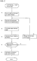
- FIG. 2 is a flowchart illustrating the travel control process according to the present embodiment.
- the travel control process described below is executed by the control device 17.
- the travel control process described below is started when the ignition switch or power switch is turned on, and repeatedly executed with a predetermined period (e.g. every 10 ms) until the ignition switch or power switch is turned off.
- a predetermined period e.g. every 10 ms
- the following description is based on an exemplary scene in which the lane-keeping travel control is input (turned on) by the driver.
- the subject vehicle information acquisition function of the control device 17 serves first to perform acquisition of the subject vehicle information regarding the traveling state of the subject vehicle.
- the subject vehicle information acquisition function can serve to acquire, as the subject vehicle information, the positional information of the subject vehicle from the subject vehicle position detection device 11 and the vehicle speed information of the subject vehicle from the vehicle speed sensor 13.
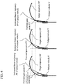
- the forward gaze point distance setting function of the control device 17 serves to provisionally set the forward gaze point P1 (see the left part of FIG. 4 ) on the basis of the current position of the subject vehicle, the traveling lane information, and the vehicle speed of the subject vehicle, for example, as illustrated in FIG. 3 .
- the provisional setting as referred to herein is to be performed on calculation for preliminarily obtaining an optimum forward gaze point distance rather than for obtaining the forward gaze point distance which is used in the actual lane-keeping travel control.
- step S2 the image data captured by the camera 14 ahead of the subject vehicle is processed, and the positional relationship between the subject vehicle and the traveling lane is detected to obtain the target trajectory. That is, the traveling lane information acquisition function of the control device 17 serves to detect the lane markers of the traveling lane located ahead of the subject vehicle and to specify the target trajectory along which the subject vehicle should travel.
- the target trajectory is, for example, the centerline of the traveling lane.
- the lateral displacement is calculated between the current position P 0 of the subject vehicle and the position P1 of the subject vehicle if the subject vehicle travels the forward gaze point distance which is provisionally set in step S1.
- the reference for the position of the subject vehicle may be, for example, the center axis of the vehicle body.
- step S3 the target steering angle with which the position of the subject vehicle coincides with the target trajectory at the forward gaze point P1 is calculated from the lateral displacement between the target trajectory at the forward gaze point P1 obtained in step S2 and the current position of the subject vehicle.
- step S4 the future subject vehicle trajectory estimation function of the control device 17 serves to use a forward gaze point model or the like to estimate the traveling trajectory of the subject vehicle if the subject vehicle is controlled with the target steering angle calculated in step S3 (see "Estimated future trajectory PP of subject vehicle" in the left part of FIG. 4 ).
- the future subject vehicle trajectory estimation function of the control device 17 serves to detect the maximum value ⁇ d max of the lateral displacement between the estimated traveling trajectory PP of the subject vehicle and the target trajectory OP during the travel from the current position P 0 of the subject vehicle to the provisionally-set forward gaze point P1.
- This detection method may include calculating a number of values of the lateral displacement ⁇ d at a predetermined interval, as illustrated in FIG. 5 , for example, and obtaining the maximum value ⁇ d max from among these values. Then, a determination is made as to whether or not the maximum value ⁇ d max of the lateral displacement is the predetermined value D or less.
- This predetermined value D may be preliminarily obtained by experiments and/or simulations as a value that allows the lane-keeping control to be achieved in which the quick followability to the target trajectory and the stability of the vehicle behavior are balanced.
- step S5 When, in step S5, the maximum value ⁇ d max of the lateral displacement is the predetermined value D or less, the process proceeds to step S7, in which the forward gaze point distance (distance between P 0 and P1 herein) having been provisionally set at that time is definitely set as an actual forward gaze point distance.
- step S6 the forward gaze point distance is changed to a forward gaze point distance between P 0 and P2 that is smaller than the forward gaze point distance between P 0 and P1 having been provisionally set at the present moment.
- the middle part of FIG. 4 is a plan view illustrating a scene in which the forward gaze point distance is changed to a forward gaze point distance between P 0 and P2 that is smaller than the forward gaze point distance between P 0 and P1 having been provisionally set last time.
- the process returns to step S2, in which the lateral displacement for the forward gaze point distance P2 and the target steering angle corresponding thereto are calculated again, and the future traveling trajectory PP of the subject vehicle is estimated again. Then, as illustrated in FIG.
- a number of values of the lateral displacement ⁇ d are calculated at a predetermined interval, and the maximum value ⁇ d max is obtained from among these values.
- the process proceeds to step S7, in which the forward gaze point distance (distance between P 0 and P2 herein) having been provisionally set at that time is definitely set as an actual forward gaze point distance.
- step S5 when, in step S5, the maximum value ⁇ d max of the lateral displacement is not the predetermined value D or less, the process proceeds to step S6, in which the forward gaze point distance is changed to a forward gaze point distance between P 0 and P3 that is smaller than the forward gaze point distance between P 0 and P2 having been provisionally set at the present moment, and the process returns to step S2.
- the process of steps S2 to S5 is repeated until the maximum value ⁇ d max of the lateral displacement becomes the predetermined value D or less.
- the right part of FIG. 4 is a plan view illustrating a scene in which the forward gaze point distance is changed to a forward gaze point distance between P 0 and P3 that is smaller than the forward gaze point distance between P 0 and P2 having been provisionally set last time.
- the forward gaze point distance to be provisionally set is successively reduced for selection as illustrated in FIG. 4 in the order of the left part ⁇ the middle part ⁇ the right part.
- the position P4 on the target trajectory OP (see FIG. 5 in detail) at which the lateral displacement between the target trajectory OP and the traveling trajectory PP of the subject vehicle estimated in the left part of FIG. 4 is the maximum value ⁇ d max may be employed as the forward gaze point distance P3 to be provisionally set next time. This is because when the forward gaze point distance between P 0 and P1 having been provisionally set in the left part of FIG.
- FIG. 6 illustrates a state in which the subject vehicle is about to enter a curve having a small curvature radius from a straight traveling lane.
- the vehicle body axis of the vehicle V coincides with the traveling direction of the vehicle V, but as the turning motion starts, a slip angle occurs between the vehicle body axis of the vehicle V and the traveling direction of the vehicle and they may not necessarily coincide with each other.
- the forward gaze point distance between P 0 and P1 will be given without consideration for the maximum error between the vehicle trajectory and the target trajectory, which is taken into account in the present embodiment.
- the shape of the target trajectory is complicated and/or when the curvature change is large, therefore, the deviation amount toward the inside of turning may possibly be a large value which cannot be ignored, and concerns are that the subject vehicle may run off the traveling lane and/or the wheels may unduly come close to curbstones.
- the opposite problem may arise when exiting a curve having a small curvature radius R toward a straight traveling lane as in the case of traveling through the exit of an intersection. That is, the curvature radius R of the road increases toward the straight traveling lane during the travel with a large slip angle along the target trajectory on the curve having a small curvature radius R. This reduces the target steering angle and the slip angle also varies to a small value, so that the traveling direction of the vehicle bulges outward with respect to the target trajectory as the vehicle travels from the exit of the curve toward the straight portion, and the vehicle may take a detour.
- the traveling trajectory PP of the subject vehicle is estimated for the provisionally-set forward gaze point distance and an appropriate forward gaze point distance is searched for until the maximum value ⁇ d max of the lateral displacement between the estimated traveling trajectory PP of the subject vehicle and the target trajectory OP becomes the predetermined value D or less.
- the forward gaze point distance to be actually set is already optimized.
- the subject vehicle can be appropriately controlled to travel in an automated or autonomous manner along the target trajectory without taking a shortcut or a detour with respect to the target trajectory.
- the forward gaze point distance to be definitely set is a distance between P 0 and P4 to the position P4 on the target trajectory at which the lateral displacement between the target trajectory OP and the traveling trajectory PP of the subject vehicle estimated on the basis of the provisionally-set forward gaze point distance is the maximum value ⁇ d max .
- the probability that the maximum value ⁇ d max of the lateral displacement becomes the predetermined value D or less is high even when the calculation of the lateral displacement between the target trajectory and the estimated trajectory of the subject vehicle is performed only once. As a result, iterative calculation is not necessary and the calculation load can be reduced.
- the forward gaze point distance to be definitely set is the maximum distance among a number of values of the forward gaze point distance in which the maximum value ⁇ d max of the lateral displacement between the target trajectory OP and the traveling trajectory PP of the subject vehicle estimated on the basis of the provisionally-set forward gaze point distance is the predetermined value D or less.
- the forward gaze point distance to be definitely set is therefore a value that allows the quick followability to the target trajectory and the stability of the vehicle behavior to be optimally balanced.
- the forward gaze point distance to be provisionally set is successively changed (e.g., successively changed to a smaller value) and the traveling trajectory of the subject vehicle is estimated again for each of the forward gaze point distances which are thus changed and set again.
- the calculation of the lateral displacement between the target trajectory OP and the estimated trajectory PP of the subject vehicle can be performed by a finite number of iterative calculations.
- the maximum value ⁇ d max of the lateral displacement between the target trajectory OP and the estimated trajectory PP of the subject vehicle is used as an evaluation index for the lane-keeping travel control and it can therefore be ensured that the maximum value ⁇ d max of the lateral displacement becomes the predetermined value D or less.
- control device 17 corresponds to the controller of the present invention.
Landscapes
- Engineering & Computer Science (AREA)
- Mechanical Engineering (AREA)
- Transportation (AREA)
- Automation & Control Theory (AREA)
- Physics & Mathematics (AREA)
- General Physics & Mathematics (AREA)
- Chemical & Material Sciences (AREA)
- Combustion & Propulsion (AREA)
- Remote Sensing (AREA)
- Aviation & Aerospace Engineering (AREA)
- Radar, Positioning & Navigation (AREA)
- Multimedia (AREA)
- Mathematical Physics (AREA)
- Human Computer Interaction (AREA)
- Theoretical Computer Science (AREA)
- Computer Vision & Pattern Recognition (AREA)
- Electromagnetism (AREA)
- Steering Control In Accordance With Driving Conditions (AREA)
- Control Of Driving Devices And Active Controlling Of Vehicle (AREA)
- Traffic Control Systems (AREA)
- Control Of Position, Course, Altitude, Or Attitude Of Moving Bodies (AREA)
Claims (6)
- Fahrsteuerverfahren für ein Fahrzeug, wobei eine Zielbewegungsbahn, entlang der ein betreffendes Fahrzeug fahren soll, erfasst wird und das betreffende Fahrzeug für eine autonome Fahrt entlang der erfassten Zielbewegungsbahn gesteuert wird,
wobei das Bewegungssteuerverfahren für ein Fahrzeug umfasst:vorläufiges Setzen einer Vorwärtsblickpunktdistanz von dem betreffenden Fahrzeug zu einem Vorwärtsblickpunkt wenigstens in Entsprechung zu den Bewegungsbahninformationen,Schätzen einer Bewegungsbahn des betreffenden Fahrzeugs, in der das betreffende Fahrzeug mit der Zielbewegungsbahn an dem Vorwärtsblickpunkt zusammenfällt, wenn das betreffende Fahrzeug über die vorläufig gesetzte Vorwärtsblickpunktdistanz fährt,wobei das Verfahren gekennzeichnet ist durch:Erfassen eines maximalen Werts einer lateralen Verschiebung zwischen der geschätzten Bewegungsbahn des betreffenden Fahrzeugs und der Zielbewegungsbahn während der Fahrt von einer aktuellen Position des betreffenden Fahrzeugs zu dem Vorwärtsblickpunkt, unddefinitives Setzen der Vorwärtsblickpunktdistanz, wenn der maximale Wert der lateralen Verschiebung ein vorbestimmter Wert oder kleiner ist, als eine tatsächliche Vorwärtsblickpunktdistanz, und dann Steuern des betreffenden Fahrzeugs für eine autonome Fahrt basierend auf der definitiv gesetzten Vorwärtsblickpunkdistanz. - Fahrsteuerverfahren für ein Fahrzeug nach Anspruch 1, wobei die definitiv zu setzende Vorwärtsblickpunktdistanz eine Distanz zu einer Position auf der Zielbewegungsbahn ist, an welcher die laterale Verschiebung zwischen der Zielbewegungsbahn und der basierend auf der vorläufig gesetzten Vorwärtsblickpunktdistanz geschätzten Bewegungsbahn des betreffenden Fahrzeugs den maximalen Wert aufweist.
- Fahrsteuerverfahren für ein Fahrzeug nach Anspruch 1, wobei die definitiv zu setzende Vorwärtsblickpunktdistanz eine maximale Distanz innerhalb einer Anzahl von Werten der Vorwärtsblickpunktdistanz ist, bei denen der maximale Wert der lateralen Verschiebung zwischen der Zielbewegungsbahn und der basierend auf der vorläufig gesetzten Vorwärtsblickpunktdistanz geschätzten Bewegungsbahn des betreffenden Fahrzeugs gleich dem vorbestimmten Wert oder kleiner ist.
- Fahrsteuerverfahren für ein Fahrzeug nach einem der Ansprüche 1 bis 3, wobei, wenn der maximale Wert der lateralen Verschiebung zwischen der Zielbewegungsbahn und der basierend auf der vorläufig gesetzten Vorwärtsblickpunktdistanz geschätzten Bewegungsbahn des betreffenden Fahrzeugs den vorbestimmten Wert überschreitet, bis der maximale Wert der lateralen Verschiebung gleich dem vorbestimmten Wert oder kleiner wird, die vorläufig zu setzende Vorwärtsblickpunktdistanz sukzessive geändert wird und die Bewegungsbahn des betreffenden Fahrzeugs erneut für die Vorwärtsblickpunktdistanz geschätzt wird, die dadurch geändert und erneut gesetzt wird.
- Fahrsteuerverfahren für ein Fahrzeug nach Anspruch 4, wobei, wenn der maximale Wert der lateralen Verschiebung zwischen der Zielbewegungsbahn und der basierend auf der vorläufig gesetzten Vorwärtsblickpunktdistanz geschätzten Bewegungsbahn des betreffenden Fahrzeugs den vorbestimmten Wert überschreitet, die vorläufig zu setzende Vorwärtsblickpunktdistanz sukzessive reduziert wird, bis der maximale Wert der lateralen Verschiebung gleich dem vorbestimmten Wert oder kleiner wird.
- Fahrsteuervorrichtung für ein Fahrzeug, die eine Steuereinrichtung umfasst, die konfiguriert ist zum Erfassen einer Zielbewegungsbahn, entlang der ein betreffendes Fahrzeug fahren soll, und zum Steuern der Fahrt des betreffenden Fahrzeugs, sodass das betreffende Fahrzeug gesteuert wird für eine autonome Fahrt entlang der erfassten Zielbewegungsbahn,
wobei die Steuereinrichtung weiterhin konfiguriert ist zum:vorläufigen Setzen einer Vorwärtsblickpunktdistanz von dem betreffenden Fahrzeug zu einem Vorwärtsblickpunkt wenigstens in Entsprechung zu den Bewegungsbahninformationen,Schätzen einer Bewegungsbahn des betreffenden Fahrzeugs, in der das betreffende Fahrzeug mit der Zielbewegungsbahn an dem Vorwärtsblickpunkt zusammenfällt, wenn das betreffende Fahrzeug über die vorläufig gesetzte Vorwärtsblickpunktdistanz fährt,wobei die Vorrichtung dadurch gekennzeichnet ist, dass die Steuereinrichtung weiterhin konfiguriert ist zum:Erfassen eines maximalen Werts einer lateralen Verschiebung zwischen der geschätzten Bewegungsbahn des betreffenden Fahrzeugs und der Zielbewegungsbahn während der Fahrt von einer aktuellen Position des betreffenden Fahrzeugs zu dem Vorwärtsblickpunkt, und
definitiven Setzen der Vorwärtsblickpunktdistanz, wenn der maximale Wert der lateralen Verschiebung ein vorbestimmter Wert oder kleiner ist, als eine tatsächliche Vorwärtsblickpunktdistanz, und dann Steuern des betreffenden Fahrzeugs für eine autonome Fahrt basierend auf der definitiv gesetzten Vorwärtsblickpunkdistanz.
Applications Claiming Priority (1)
| Application Number | Priority Date | Filing Date | Title |
|---|---|---|---|
| PCT/JP2016/076600 WO2018047292A1 (ja) | 2016-09-09 | 2016-09-09 | 車両の走行制御方法および走行制御装置 |
Publications (3)
| Publication Number | Publication Date |
|---|---|
| EP3511922A1 EP3511922A1 (de) | 2019-07-17 |
| EP3511922A4 EP3511922A4 (de) | 2019-08-28 |
| EP3511922B1 true EP3511922B1 (de) | 2020-02-19 |
Family
ID=61562650
Family Applications (1)
| Application Number | Title | Priority Date | Filing Date |
|---|---|---|---|
| EP16915710.4A Active EP3511922B1 (de) | 2016-09-09 | 2016-09-09 | Fahrzeugfahrtsteuerungsverfahren und fahrtsteuerungsvorrichtung |
Country Status (10)
| Country | Link |
|---|---|
| US (1) | US10474158B2 (de) |
| EP (1) | EP3511922B1 (de) |
| JP (1) | JP6610799B2 (de) |
| KR (1) | KR102057428B1 (de) |
| CN (1) | CN109690651B (de) |
| BR (1) | BR112019004582B1 (de) |
| CA (1) | CA3036337A1 (de) |
| MX (1) | MX373578B (de) |
| RU (1) | RU2715667C1 (de) |
| WO (1) | WO2018047292A1 (de) |
Families Citing this family (10)
| Publication number | Priority date | Publication date | Assignee | Title |
|---|---|---|---|---|
| BR112019004582B1 (pt) * | 2016-09-09 | 2023-12-26 | Nissan Motor Co., Ltd | Método e aparelho de controle de deslocamento para um veículo |
| WO2019186692A1 (ja) * | 2018-03-27 | 2019-10-03 | 日産自動車株式会社 | 自動運転車両の制御方法および制御装置 |
| FR3088590B1 (fr) * | 2018-11-16 | 2020-10-23 | Psa Automobiles Sa | Regulation de la vitesse d’un vehicule, avec prise en compte de la volonte du conducteur dans un virage |
| FR3094317B1 (fr) * | 2019-04-01 | 2021-03-05 | Renault Sas | Module anticipateur, dispositif de contrôle en temps réel de trajectoire et procédé associés |
| US11423674B2 (en) * | 2020-10-22 | 2022-08-23 | Ford Global Technologies, Llc | Vehicle occupant gaze detection |
| CN112578792B (zh) * | 2020-11-12 | 2022-05-31 | 东风汽车集团有限公司 | 一种十字路口辅助控制方法及存储介质 |
| DE102021202278A1 (de) * | 2021-03-09 | 2022-09-15 | Robert Bosch Gesellschaft mit beschränkter Haftung | Vorrichtung und Verfahren zum Beeinflussen und/oder Betreiben eines Lenksystems und Lenksystem insbesondere für ein Fahrzeug |
| CN113022570B (zh) * | 2021-03-19 | 2022-06-10 | 武汉理工大学 | 一种车辆换道行为识别方法及设备 |
| CN118382570A (zh) | 2021-12-07 | 2024-07-23 | 日立安斯泰莫株式会社 | 车辆控制装置、车辆控制方法以及车辆控制系统 |
| KR102928664B1 (ko) * | 2024-10-17 | 2026-02-20 | 주식회사 긴트 | 농기계의 자율주행성능 개선 방법 및 그 장치 |
Family Cites Families (34)
| Publication number | Priority date | Publication date | Assignee | Title |
|---|---|---|---|---|
| JP3575343B2 (ja) * | 1999-08-02 | 2004-10-13 | 日産自動車株式会社 | 車線追従装置 |
| JP2002002427A (ja) * | 2000-06-15 | 2002-01-09 | Mazda Motor Corp | 車両用制御装置 |
| JP3637849B2 (ja) * | 2000-07-06 | 2005-04-13 | 日産自動車株式会社 | 車線追従走行制御装置 |
| JP3539362B2 (ja) * | 2000-07-07 | 2004-07-07 | 日産自動車株式会社 | 車線追従走行制御装置 |
| JP3498910B2 (ja) * | 2000-09-05 | 2004-02-23 | 日産自動車株式会社 | 車線追従制御装置 |
| JP3603768B2 (ja) * | 2000-09-06 | 2004-12-22 | 日産自動車株式会社 | 車線逸脱判定装置 |
| JP3649119B2 (ja) * | 2000-12-12 | 2005-05-18 | 日産自動車株式会社 | レーンキープアシスト制御装置 |
| JP3780922B2 (ja) * | 2001-11-30 | 2006-05-31 | 日産自動車株式会社 | 道路白線認識装置 |
| JP3922194B2 (ja) * | 2003-03-11 | 2007-05-30 | 日産自動車株式会社 | 車線逸脱警報装置 |
| JP3982483B2 (ja) * | 2003-11-13 | 2007-09-26 | 日産自動車株式会社 | 車線逸脱防止装置 |
| JP2005182186A (ja) * | 2003-12-16 | 2005-07-07 | Toyota Motor Corp | 車両用走行軌道設定装置 |
| JP5150958B2 (ja) | 2008-03-31 | 2013-02-27 | 本田技研工業株式会社 | 車両走行支援装置、車両、車両走行支援プログラム |
| DE102009047476A1 (de) * | 2009-12-04 | 2011-06-09 | Robert Bosch Gmbh | Verfahren und Steuergerät zur Bestimmung einer Schnitttrajektorie eines Kurvenabschnitts einer Fahrbahn |
| DE102010039399A1 (de) * | 2010-08-17 | 2012-02-23 | Visteon Global Technologies, Inc. | Prädiktiv-adaptive Frontbeleuchtung eines Kraftfahrzeuges |
| DE102010040650B4 (de) * | 2010-09-13 | 2020-08-13 | Robert Bosch Gmbh | Vorrichtung und Verfahren zur Einstellung der Beleuchtung eines Fahrzeugs bei uneinsichtigen Kurven |
| JP5417386B2 (ja) * | 2011-07-01 | 2014-02-12 | 日立オートモティブシステムズ株式会社 | 車両運動制御装置 |
| JP5790401B2 (ja) * | 2011-10-24 | 2015-10-07 | 日産自動車株式会社 | 車両用走行支援装置 |
| CN103917432B (zh) * | 2011-11-08 | 2016-06-15 | 丰田自动车株式会社 | 车辆的行驶轨迹控制装置 |
| US20150266508A1 (en) * | 2012-10-25 | 2015-09-24 | Nissan Motor Co., Ltd. | Vehicle travel assistance device |
| JP6020224B2 (ja) * | 2013-02-07 | 2016-11-02 | トヨタ自動車株式会社 | 目標走行軌跡生成装置 |
| JP5783204B2 (ja) * | 2013-05-01 | 2015-09-24 | トヨタ自動車株式会社 | 運転支援装置および運転支援方法 |
| JP5802241B2 (ja) * | 2013-07-04 | 2015-10-28 | 富士重工業株式会社 | 車両の運転支援制御装置 |
| JP5988308B2 (ja) | 2013-12-27 | 2016-09-07 | 富士重工業株式会社 | 車両のレーンキープ制御装置 |
| DE102014200687A1 (de) * | 2014-01-16 | 2015-07-16 | Robert Bosch Gmbh | Verfahren zum Betreiben eines Fahrzeugs |
| US9862382B2 (en) * | 2014-08-11 | 2018-01-09 | Nissan Motor Co., Ltd. | Travel control device and method for vehicle |
| JP6384296B2 (ja) | 2014-12-02 | 2018-09-05 | 日産自動車株式会社 | 車両の操舵制御装置及び車両の操舵制御方法 |
| US9616926B2 (en) * | 2015-01-28 | 2017-04-11 | Hyundai Motor Company | Steering assistance apparatus and method for vehicles |
| JP6553917B2 (ja) * | 2015-03-31 | 2019-07-31 | アイシン・エィ・ダブリュ株式会社 | 自動運転支援システム、自動運転支援方法及びコンピュータプログラム |
| JP6412460B2 (ja) * | 2015-04-14 | 2018-10-24 | 株式会社Soken | 走行路推定装置 |
| JP6332170B2 (ja) * | 2015-07-01 | 2018-05-30 | トヨタ自動車株式会社 | 自動運転制御装置 |
| JP6246844B2 (ja) * | 2016-02-18 | 2017-12-13 | 本田技研工業株式会社 | 車両制御システム、車両制御方法、および車両制御プログラム |
| JP6614025B2 (ja) * | 2016-05-20 | 2019-12-04 | アイシン・エィ・ダブリュ株式会社 | 自動運転支援装置及びコンピュータプログラム |
| US10046762B2 (en) * | 2016-08-18 | 2018-08-14 | GM Global Technology Operations LLC | Trajectory integrity co-pilot for autonomous vehicle |
| BR112019004582B1 (pt) * | 2016-09-09 | 2023-12-26 | Nissan Motor Co., Ltd | Método e aparelho de controle de deslocamento para um veículo |
-
2016
- 2016-09-09 BR BR112019004582-1A patent/BR112019004582B1/pt not_active IP Right Cessation
- 2016-09-09 KR KR1020197005685A patent/KR102057428B1/ko not_active Expired - Fee Related
- 2016-09-09 EP EP16915710.4A patent/EP3511922B1/de active Active
- 2016-09-09 US US16/331,431 patent/US10474158B2/en active Active
- 2016-09-09 RU RU2019110265A patent/RU2715667C1/ru active
- 2016-09-09 MX MX2019002591A patent/MX373578B/es active IP Right Grant
- 2016-09-09 WO PCT/JP2016/076600 patent/WO2018047292A1/ja not_active Ceased
- 2016-09-09 CN CN201680089087.1A patent/CN109690651B/zh active Active
- 2016-09-09 CA CA3036337A patent/CA3036337A1/en not_active Abandoned
- 2016-09-09 JP JP2018537945A patent/JP6610799B2/ja active Active
Also Published As
| Publication number | Publication date |
|---|---|
| US10474158B2 (en) | 2019-11-12 |
| BR112019004582B1 (pt) | 2023-12-26 |
| MX2019002591A (es) | 2019-07-04 |
| US20190227563A1 (en) | 2019-07-25 |
| KR20190030757A (ko) | 2019-03-22 |
| JP6610799B2 (ja) | 2019-11-27 |
| BR112019004582A2 (pt) | 2019-06-11 |
| CN109690651B (zh) | 2020-09-08 |
| WO2018047292A1 (ja) | 2018-03-15 |
| KR102057428B1 (ko) | 2019-12-18 |
| MX373578B (es) | 2020-05-05 |
| CN109690651A (zh) | 2019-04-26 |
| EP3511922A1 (de) | 2019-07-17 |
| JPWO2018047292A1 (ja) | 2019-06-24 |
| EP3511922A4 (de) | 2019-08-28 |
| RU2715667C1 (ru) | 2020-03-02 |
| CA3036337A1 (en) | 2018-03-15 |
Similar Documents
| Publication | Publication Date | Title |
|---|---|---|
| US10474158B2 (en) | Vehicle travel control method and travel control device | |
| US11526173B2 (en) | Traveling trajectory correction method, traveling control method, and traveling trajectory correction device | |
| EP3644294B1 (de) | Fahrzeuginformationspeicherverfahren, fahrzeugfahrsteuerungsverfahren und fahrzeuginformationspeichervorrichtung | |
| KR101551096B1 (ko) | 자율주행차량의 차선변경장치 및 방법 | |
| CN106794838B (zh) | 用于至少半自主操纵机动车辆的方法、驾驶员辅助系统和机动车辆 | |
| CN109305160B (zh) | 用于自主驾驶的路径规划 | |
| CN106080598B (zh) | 实时预期速度控制 | |
| CN107200012B (zh) | 车辆的行驶控制装置 | |
| EP3243686B1 (de) | Vorrichtung zur erzeugung einer zielroute und antriebssteuerungsvorrichtung | |
| US20190359215A1 (en) | Vehicle Travel Control Method and Travel Control Device | |
| RU2735720C1 (ru) | Способ оценки транспортного средства, способ корректировки маршрута движения, устройство оценки транспортного средства и устройство корректировки маршрута движения | |
| US20120277955A1 (en) | Driving assistance device | |
| CN105539434A (zh) | 用于躲避转向操作的路径规划方法 | |
| JP2012504269A (ja) | システム操作者支援のための支援制御装置を備えたシステム、制御操作支援装置、制御操作支援方法、運転操作支援装置、及び運転操作支援方法 | |
| US20200193176A1 (en) | Automatic driving controller and method | |
| JP2016224802A (ja) | 車両制御装置及びプログラム | |
| US20200307612A1 (en) | Vehicle control device | |
| WO2016194168A1 (ja) | 走行制御装置及び方法 | |
| EP3517380A1 (de) | Verfahren zur steuerung der fahrt und vorrichtung zur steuerung der fahrt eines fahrzeugs | |
| EP4046894B1 (de) | Vorrangigkeitsbestimmungsverfahren für eine fahrassistenzvorrichtung und fahrassistenzvorrichtung | |
| EP3626570B1 (de) | Fahrassistenzverfahren und fahrassistenzvorrichtung | |
| CN117999216A (zh) | 用于对在具有多个车道的道路上的车辆进行自动横向引导期间支持车辆用户的方法、计算装置和驾驶辅助系统 | |
| JPWO2016110730A1 (ja) | 目標車速生成装置および走行制御装置 | |
| US20240067229A1 (en) | Vehicle control device, vehicle control method, and storage medium | |
| JP7724119B2 (ja) | 操舵制御方法及び操舵制御装置 |
Legal Events
| Date | Code | Title | Description |
|---|---|---|---|
| STAA | Information on the status of an ep patent application or granted ep patent |
Free format text: STATUS: THE INTERNATIONAL PUBLICATION HAS BEEN MADE |
|
| PUAI | Public reference made under article 153(3) epc to a published international application that has entered the european phase |
Free format text: ORIGINAL CODE: 0009012 |
|
| STAA | Information on the status of an ep patent application or granted ep patent |
Free format text: STATUS: REQUEST FOR EXAMINATION WAS MADE |
|
| 17P | Request for examination filed |
Effective date: 20190402 |
|
| AK | Designated contracting states |
Kind code of ref document: A1 Designated state(s): AL AT BE BG CH CY CZ DE DK EE ES FI FR GB GR HR HU IE IS IT LI LT LU LV MC MK MT NL NO PL PT RO RS SE SI SK SM TR |
|
| AX | Request for extension of the european patent |
Extension state: BA ME |
|
| A4 | Supplementary search report drawn up and despatched |
Effective date: 20190726 |
|
| RIC1 | Information provided on ipc code assigned before grant |
Ipc: B60W 30/12 20060101ALI20190722BHEP Ipc: B60W 30/18 20120101ALI20190722BHEP Ipc: B62D 15/02 20060101ALI20190722BHEP Ipc: B60R 21/00 20060101ALI20190722BHEP Ipc: B60W 30/02 20120101ALI20190722BHEP Ipc: G05D 1/02 20060101ALI20190722BHEP Ipc: G08G 1/16 20060101AFI20190722BHEP Ipc: B62D 6/00 20060101ALI20190722BHEP |
|
| GRAP | Despatch of communication of intention to grant a patent |
Free format text: ORIGINAL CODE: EPIDOSNIGR1 |
|
| STAA | Information on the status of an ep patent application or granted ep patent |
Free format text: STATUS: GRANT OF PATENT IS INTENDED |
|
| DAV | Request for validation of the european patent (deleted) | ||
| DAX | Request for extension of the european patent (deleted) | ||
| INTG | Intention to grant announced |
Effective date: 20191118 |
|
| GRAS | Grant fee paid |
Free format text: ORIGINAL CODE: EPIDOSNIGR3 |
|
| GRAA | (expected) grant |
Free format text: ORIGINAL CODE: 0009210 |
|
| STAA | Information on the status of an ep patent application or granted ep patent |
Free format text: STATUS: THE PATENT HAS BEEN GRANTED |
|
| AK | Designated contracting states |
Kind code of ref document: B1 Designated state(s): AL AT BE BG CH CY CZ DE DK EE ES FI FR GB GR HR HU IE IS IT LI LT LU LV MC MK MT NL NO PL PT RO RS SE SI SK SM TR |
|
| REG | Reference to a national code |
Ref country code: CH Ref legal event code: EP |
|
| REG | Reference to a national code |
Ref country code: DE Ref legal event code: R096 Ref document number: 602016030367 Country of ref document: DE |
|
| REG | Reference to a national code |
Ref country code: AT Ref legal event code: REF Ref document number: 1235846 Country of ref document: AT Kind code of ref document: T Effective date: 20200315 |
|
| REG | Reference to a national code |
Ref country code: IE Ref legal event code: FG4D |
|
| REG | Reference to a national code |
Ref country code: NL Ref legal event code: MP Effective date: 20200219 |
|
| PG25 | Lapsed in a contracting state [announced via postgrant information from national office to epo] |
Ref country code: FI Free format text: LAPSE BECAUSE OF FAILURE TO SUBMIT A TRANSLATION OF THE DESCRIPTION OR TO PAY THE FEE WITHIN THE PRESCRIBED TIME-LIMIT Effective date: 20200219 Ref country code: NO Free format text: LAPSE BECAUSE OF FAILURE TO SUBMIT A TRANSLATION OF THE DESCRIPTION OR TO PAY THE FEE WITHIN THE PRESCRIBED TIME-LIMIT Effective date: 20200519 Ref country code: RS Free format text: LAPSE BECAUSE OF FAILURE TO SUBMIT A TRANSLATION OF THE DESCRIPTION OR TO PAY THE FEE WITHIN THE PRESCRIBED TIME-LIMIT Effective date: 20200219 |
|
| REG | Reference to a national code |
Ref country code: LT Ref legal event code: MG4D |
|
| PG25 | Lapsed in a contracting state [announced via postgrant information from national office to epo] |
Ref country code: LV Free format text: LAPSE BECAUSE OF FAILURE TO SUBMIT A TRANSLATION OF THE DESCRIPTION OR TO PAY THE FEE WITHIN THE PRESCRIBED TIME-LIMIT Effective date: 20200219 Ref country code: SE Free format text: LAPSE BECAUSE OF FAILURE TO SUBMIT A TRANSLATION OF THE DESCRIPTION OR TO PAY THE FEE WITHIN THE PRESCRIBED TIME-LIMIT Effective date: 20200219 Ref country code: IS Free format text: LAPSE BECAUSE OF FAILURE TO SUBMIT A TRANSLATION OF THE DESCRIPTION OR TO PAY THE FEE WITHIN THE PRESCRIBED TIME-LIMIT Effective date: 20200619 Ref country code: HR Free format text: LAPSE BECAUSE OF FAILURE TO SUBMIT A TRANSLATION OF THE DESCRIPTION OR TO PAY THE FEE WITHIN THE PRESCRIBED TIME-LIMIT Effective date: 20200219 Ref country code: BG Free format text: LAPSE BECAUSE OF FAILURE TO SUBMIT A TRANSLATION OF THE DESCRIPTION OR TO PAY THE FEE WITHIN THE PRESCRIBED TIME-LIMIT Effective date: 20200519 Ref country code: GR Free format text: LAPSE BECAUSE OF FAILURE TO SUBMIT A TRANSLATION OF THE DESCRIPTION OR TO PAY THE FEE WITHIN THE PRESCRIBED TIME-LIMIT Effective date: 20200520 |
|
| PG25 | Lapsed in a contracting state [announced via postgrant information from national office to epo] |
Ref country code: NL Free format text: LAPSE BECAUSE OF FAILURE TO SUBMIT A TRANSLATION OF THE DESCRIPTION OR TO PAY THE FEE WITHIN THE PRESCRIBED TIME-LIMIT Effective date: 20200219 |
|
| PG25 | Lapsed in a contracting state [announced via postgrant information from national office to epo] |
Ref country code: LT Free format text: LAPSE BECAUSE OF FAILURE TO SUBMIT A TRANSLATION OF THE DESCRIPTION OR TO PAY THE FEE WITHIN THE PRESCRIBED TIME-LIMIT Effective date: 20200219 Ref country code: DK Free format text: LAPSE BECAUSE OF FAILURE TO SUBMIT A TRANSLATION OF THE DESCRIPTION OR TO PAY THE FEE WITHIN THE PRESCRIBED TIME-LIMIT Effective date: 20200219 Ref country code: SM Free format text: LAPSE BECAUSE OF FAILURE TO SUBMIT A TRANSLATION OF THE DESCRIPTION OR TO PAY THE FEE WITHIN THE PRESCRIBED TIME-LIMIT Effective date: 20200219 Ref country code: EE Free format text: LAPSE BECAUSE OF FAILURE TO SUBMIT A TRANSLATION OF THE DESCRIPTION OR TO PAY THE FEE WITHIN THE PRESCRIBED TIME-LIMIT Effective date: 20200219 Ref country code: RO Free format text: LAPSE BECAUSE OF FAILURE TO SUBMIT A TRANSLATION OF THE DESCRIPTION OR TO PAY THE FEE WITHIN THE PRESCRIBED TIME-LIMIT Effective date: 20200219 Ref country code: CZ Free format text: LAPSE BECAUSE OF FAILURE TO SUBMIT A TRANSLATION OF THE DESCRIPTION OR TO PAY THE FEE WITHIN THE PRESCRIBED TIME-LIMIT Effective date: 20200219 Ref country code: ES Free format text: LAPSE BECAUSE OF FAILURE TO SUBMIT A TRANSLATION OF THE DESCRIPTION OR TO PAY THE FEE WITHIN THE PRESCRIBED TIME-LIMIT Effective date: 20200219 Ref country code: PT Free format text: LAPSE BECAUSE OF FAILURE TO SUBMIT A TRANSLATION OF THE DESCRIPTION OR TO PAY THE FEE WITHIN THE PRESCRIBED TIME-LIMIT Effective date: 20200712 Ref country code: SK Free format text: LAPSE BECAUSE OF FAILURE TO SUBMIT A TRANSLATION OF THE DESCRIPTION OR TO PAY THE FEE WITHIN THE PRESCRIBED TIME-LIMIT Effective date: 20200219 |
|
| REG | Reference to a national code |
Ref country code: AT Ref legal event code: MK05 Ref document number: 1235846 Country of ref document: AT Kind code of ref document: T Effective date: 20200219 |
|
| REG | Reference to a national code |
Ref country code: DE Ref legal event code: R097 Ref document number: 602016030367 Country of ref document: DE |
|
| PLBE | No opposition filed within time limit |
Free format text: ORIGINAL CODE: 0009261 |
|
| STAA | Information on the status of an ep patent application or granted ep patent |
Free format text: STATUS: NO OPPOSITION FILED WITHIN TIME LIMIT |
|
| 26N | No opposition filed |
Effective date: 20201120 |
|
| PG25 | Lapsed in a contracting state [announced via postgrant information from national office to epo] |
Ref country code: AT Free format text: LAPSE BECAUSE OF FAILURE TO SUBMIT A TRANSLATION OF THE DESCRIPTION OR TO PAY THE FEE WITHIN THE PRESCRIBED TIME-LIMIT Effective date: 20200219 Ref country code: IT Free format text: LAPSE BECAUSE OF FAILURE TO SUBMIT A TRANSLATION OF THE DESCRIPTION OR TO PAY THE FEE WITHIN THE PRESCRIBED TIME-LIMIT Effective date: 20200219 |
|
| PG25 | Lapsed in a contracting state [announced via postgrant information from national office to epo] |
Ref country code: PL Free format text: LAPSE BECAUSE OF FAILURE TO SUBMIT A TRANSLATION OF THE DESCRIPTION OR TO PAY THE FEE WITHIN THE PRESCRIBED TIME-LIMIT Effective date: 20200219 |
|
| REG | Reference to a national code |
Ref country code: CH Ref legal event code: PL |
|
| REG | Reference to a national code |
Ref country code: BE Ref legal event code: MM Effective date: 20200930 |
|
| PG25 | Lapsed in a contracting state [announced via postgrant information from national office to epo] |
Ref country code: LU Free format text: LAPSE BECAUSE OF NON-PAYMENT OF DUE FEES Effective date: 20200909 |
|
| PG25 | Lapsed in a contracting state [announced via postgrant information from national office to epo] |
Ref country code: LI Free format text: LAPSE BECAUSE OF NON-PAYMENT OF DUE FEES Effective date: 20200930 Ref country code: IE Free format text: LAPSE BECAUSE OF NON-PAYMENT OF DUE FEES Effective date: 20200909 Ref country code: CH Free format text: LAPSE BECAUSE OF NON-PAYMENT OF DUE FEES Effective date: 20200930 Ref country code: BE Free format text: LAPSE BECAUSE OF NON-PAYMENT OF DUE FEES Effective date: 20200930 |
|
| PG25 | Lapsed in a contracting state [announced via postgrant information from national office to epo] |
Ref country code: TR Free format text: LAPSE BECAUSE OF FAILURE TO SUBMIT A TRANSLATION OF THE DESCRIPTION OR TO PAY THE FEE WITHIN THE PRESCRIBED TIME-LIMIT Effective date: 20200219 Ref country code: MT Free format text: LAPSE BECAUSE OF FAILURE TO SUBMIT A TRANSLATION OF THE DESCRIPTION OR TO PAY THE FEE WITHIN THE PRESCRIBED TIME-LIMIT Effective date: 20200219 Ref country code: CY Free format text: LAPSE BECAUSE OF FAILURE TO SUBMIT A TRANSLATION OF THE DESCRIPTION OR TO PAY THE FEE WITHIN THE PRESCRIBED TIME-LIMIT Effective date: 20200219 |
|
| PG25 | Lapsed in a contracting state [announced via postgrant information from national office to epo] |
Ref country code: MK Free format text: LAPSE BECAUSE OF FAILURE TO SUBMIT A TRANSLATION OF THE DESCRIPTION OR TO PAY THE FEE WITHIN THE PRESCRIBED TIME-LIMIT Effective date: 20200219 Ref country code: MC Free format text: LAPSE BECAUSE OF FAILURE TO SUBMIT A TRANSLATION OF THE DESCRIPTION OR TO PAY THE FEE WITHIN THE PRESCRIBED TIME-LIMIT Effective date: 20200219 Ref country code: AL Free format text: LAPSE BECAUSE OF FAILURE TO SUBMIT A TRANSLATION OF THE DESCRIPTION OR TO PAY THE FEE WITHIN THE PRESCRIBED TIME-LIMIT Effective date: 20200219 |
|
| PG25 | Lapsed in a contracting state [announced via postgrant information from national office to epo] |
Ref country code: SI Free format text: LAPSE BECAUSE OF FAILURE TO SUBMIT A TRANSLATION OF THE DESCRIPTION OR TO PAY THE FEE WITHIN THE PRESCRIBED TIME-LIMIT Effective date: 20200219 |
|
| PGFP | Annual fee paid to national office [announced via postgrant information from national office to epo] |
Ref country code: DE Payment date: 20250820 Year of fee payment: 10 |
|
| PGFP | Annual fee paid to national office [announced via postgrant information from national office to epo] |
Ref country code: GB Payment date: 20250822 Year of fee payment: 10 |
|
| PGFP | Annual fee paid to national office [announced via postgrant information from national office to epo] |
Ref country code: FR Payment date: 20250821 Year of fee payment: 10 |