EP3510200B1 - Gleisverfahrbare maschine zum abtragen von unregelmässigkeiten an einer schienenkopfoberfläche - Google Patents
Gleisverfahrbare maschine zum abtragen von unregelmässigkeiten an einer schienenkopfoberfläche Download PDFInfo
- Publication number
- EP3510200B1 EP3510200B1 EP17752288.5A EP17752288A EP3510200B1 EP 3510200 B1 EP3510200 B1 EP 3510200B1 EP 17752288 A EP17752288 A EP 17752288A EP 3510200 B1 EP3510200 B1 EP 3510200B1
- Authority
- EP
- European Patent Office
- Prior art keywords
- tool
- rail
- machine
- frame
- treatment machine
- Prior art date
- Legal status (The legal status is an assumption and is not a legal conclusion. Google has not performed a legal analysis and makes no representation as to the accuracy of the status listed.)
- Active
Links
- 238000000227 grinding Methods 0.000 claims description 3
- 238000003801 milling Methods 0.000 claims description 2
- 238000003754 machining Methods 0.000 description 16
- 238000012545 processing Methods 0.000 description 8
- 230000006978 adaptation Effects 0.000 description 3
- 238000011161 development Methods 0.000 description 2
- 239000000463 material Substances 0.000 description 2
- 238000012549 training Methods 0.000 description 2
- 238000012546 transfer Methods 0.000 description 2
- 230000005540 biological transmission Effects 0.000 description 1
- 239000000969 carrier Substances 0.000 description 1
- 238000002485 combustion reaction Methods 0.000 description 1
- 230000007547 defect Effects 0.000 description 1
- 238000013461 design Methods 0.000 description 1
- 239000000725 suspension Substances 0.000 description 1
Images


Classifications
-
- E—FIXED CONSTRUCTIONS
- E01—CONSTRUCTION OF ROADS, RAILWAYS, OR BRIDGES
- E01B—PERMANENT WAY; PERMANENT-WAY TOOLS; MACHINES FOR MAKING RAILWAYS OF ALL KINDS
- E01B31/00—Working rails, sleepers, baseplates, or the like, in or on the line; Machines, tools, or auxiliary devices specially designed therefor
- E01B31/02—Working rail or other metal track components on the spot
- E01B31/12—Removing metal from rails, rail joints, or baseplates, e.g. for deburring welds, reconditioning worn rails
- E01B31/13—Removing metal from rails, rail joints, or baseplates, e.g. for deburring welds, reconditioning worn rails by milling
-
- E—FIXED CONSTRUCTIONS
- E01—CONSTRUCTION OF ROADS, RAILWAYS, OR BRIDGES
- E01B—PERMANENT WAY; PERMANENT-WAY TOOLS; MACHINES FOR MAKING RAILWAYS OF ALL KINDS
- E01B31/00—Working rails, sleepers, baseplates, or the like, in or on the line; Machines, tools, or auxiliary devices specially designed therefor
- E01B31/02—Working rail or other metal track components on the spot
- E01B31/12—Removing metal from rails, rail joints, or baseplates, e.g. for deburring welds, reconditioning worn rails
- E01B31/17—Removing metal from rails, rail joints, or baseplates, e.g. for deburring welds, reconditioning worn rails by grinding
Definitions
- the invention relates to a track-working rail processing machine for removing irregularities on a rail head surface of at least one rail of a laid track, with a machine frame supported on a front rail running gear viewed in a working direction and on a rear rail running gear and a tool frame for receiving at least one tool carrier.
- Rail processing machines for processing a rail head surface are already known from various applications.
- the defects present in the rail mirror are removed by a machining tool.
- AT 513 035 B1 a device for grinding rails of a track, in which grindstones arranged one behind the other in the longitudinal direction of the rail and each associated with a rail are provided, each grindstone being deliverable by means of a drive in the vertical direction or to a rail running surface.
- a processing machine is known in which a tool carrier is articulated to a machine frame via a hydraulic piston-cylinder unit.
- the object of the present invention is to provide a device of the type mentioned at the outset, with which an exact adaptation of the machining tools to the track geometry and an inexpensive and economical rail machining is possible.
- this object is achieved in that the machine frame is supported on a front rail undercarriage viewed in the working direction and on a rear rail undercarriage and in that the tool frame is articulated with a rear end on the rear rail undercarriage on a vertical axis of rotation in a pivot point and with a front end a separate rail undercarriage located between the front and rear rail undercarriages is supported.
- This training ensures that the tool frame and thus the machining tool are adapted to the track geometry independently of the machine frame. This results in a high surface quality of the rails with a resulting noise reduction when driving on them.
- a sensible development provides that the rear rail carriage is designed as a bogie and that the machine frame is supported on the bogie so that it can rotate about the vertical axis of rotation.
- the own rail chassis of the tool frame is designed as a supported bogie. It is advantageous if support elements can be activated for a work trip by means of a control in the respective supported bogie. It is then possible to switch off the respective support during a transfer run in order to improve the driving properties of the rail processing machine.
- a swiveling chip collector located above the tool frame is arranged on the machine frame. It is possible to collect the chips removed from the rail surface in a closed manner so that they can then be unloaded in a targeted and environmentally friendly manner onto a designated unloading area or a loading area of a truck or transport wagon next to the track.
- Another embodiment of the invention provides that a machining tool located on the tool carrier has a floating bearing. In combination with the support of the rear and the own rail chassis, this results in an independent adaptation of the tool holder to both rails.
- a sensible embodiment is realized in that a machining tool located on the tool carrier is designed as a milling tool. As a result, high material removal can be achieved, for example, in the event of grooves.
- a further design ensures that a machining tool located on the tool carrier is designed as a grinding tool.
- a particularly high surface quality of the rail head can be achieved in this way.
- a further advantage is given when the machining tool is designed to be pivotable from a transport position into a working position. This considerably facilitates the mobility during transfer rides.
- the respective processing tool is equipped with its own drive. This means that no central drive of the machine is required and the machining tool can be operated independently.
- the machine is designed as a traction vehicle with its own engine. As a result, no additional traction vehicle would be necessary for the mobility on the track.
- the machine 1 shown on a track 2 for removing irregularities on a rail head surface 3 comprises a machine frame 7 supported on a front rail carriage 5 viewed in the working direction 4 and a rear rail carriage 6.
- a tool frame 8 is at a rear end 9 above the rear rail carriage 6 on a vertical axis of rotation 10 in a pivot point 11 is articulated and supported with a front end 12 on a separate rail undercarriage 13 located between the front 5 and the rear rail undercarriage 6.
- the rear rail carriage 6 and the own rail carriage 13 are designed as a supported bogie.
- Arranged on the tool frame 8 are two tool carriers 14 which can be pivoted from a transport position into a working position, together with machining tools 15 with a floating bearing 16.
- a chip collector 19 which can be pivoted about an axis, is arranged between the machine frame 7 and the tool frame 8. For emptying, the chip collector 19 is raised by means of a lifting arm and pivoted laterally about the axis.
- Fig. 1 shows a working position shown in full line and a transport position of the tool carrier 14 and machining tools 15 shown in dashed line. Each machining tool can advantageously be acted upon by its own drive 38.
- a supply device 39 for supplying the drives 38 of the machining tools 15 is provided below the machine frame 7. This is, for example, an internal combustion engine that drives hydraulic pumps of a hydraulic system or a generator via a transmission.
- the respective supported bogie comprises a bogie frame 20 and rail wheels 22 arranged on two wheel axles 21.
- Two springs 24 are positioned between the bogie frame 20 and a spring plate 23 arranged on each side below the respective wheel axle 21.
- a hydraulic cylinder 25 per wheel suspension and a second cylinder 26 without hydraulics are arranged on the associated spring plate 23 or axle bearing as supporting elements on the bogie frame 20.
- a second piston 31 is arranged in the second cylinder 26 and is connected to the first piston 28 by a piston rod 32.
- Fig. 2 the bogie is in the relaxed state and is therefore not pressurized via the hydraulic line 30.
- the first piston 28 is in the lowered state and the springs 24 are therefore not preloaded. The support of the respective bogie is thus deactivated.
- Fig. 3 an activated support is shown.
- the hydraulic cylinder 25 is pressurized via the hydraulic line 30 so that the first piston 28 is pressed upward.
- the second piston 31 connected to the first piston 28 via the piston rod 32 is forcibly moved in the direction of the hydraulic cylinder 25 and prestresses the springs 24.
- the bias of the springs 24 results in a more stable support and thus a more precise machining of the rail head surface 3.
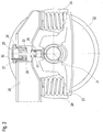
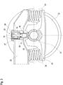
- Fig. 4 and Fig. 5 the storage in the articulation point 11 is shown.
- the rear end 9 of the tool frame 8 is articulated on a guide pin 34 located on a vertical axis of rotation 10.
- the guide pin 34 is locked in the machine frame 7 and has a conical recess 36 at its upper end 35, which serves as a stop for the tool frame 8.
- Bearing shells 37 with spherical outer surfaces with the articulation point 11 as a common center point are arranged around the guide pin 34.
- Bearing shells 40 with corresponding spherical inner surfaces are arranged in the tool frame 8, so that free tilting and rotating movements of the tool frame 8 around the articulation point 11 are possible.
- Fig. 5 the freedom of movement of the tool frame 8 relative to the machine frame 7 is shown in a horizontal plane. So that can the machining tools 15 follow the rails 18 even in tight curve radii.
Applications Claiming Priority (2)
| Application Number | Priority Date | Filing Date | Title |
|---|---|---|---|
| ATA413/2016A AT519049B1 (de) | 2016-09-07 | 2016-09-07 | Gleisverfahrbare Maschine zum Abtragen von Unregelmäßigkeiten an einer Schienenkopfoberfläche |
| PCT/EP2017/000967 WO2018046115A1 (de) | 2016-09-07 | 2017-08-09 | Gleisverfahrbare maschine zum abtragen von unregelmässigkeiten an einer schienenkopfoberfläche |
Publications (2)
| Publication Number | Publication Date |
|---|---|
| EP3510200A1 EP3510200A1 (de) | 2019-07-17 |
| EP3510200B1 true EP3510200B1 (de) | 2020-08-05 |
Family
ID=59631716
Family Applications (1)
| Application Number | Title | Priority Date | Filing Date |
|---|---|---|---|
| EP17752288.5A Active EP3510200B1 (de) | 2016-09-07 | 2017-08-09 | Gleisverfahrbare maschine zum abtragen von unregelmässigkeiten an einer schienenkopfoberfläche |
Country Status (10)
| Country | Link |
|---|---|
| US (1) | US11203839B2 (pt) |
| EP (1) | EP3510200B1 (pt) |
| JP (1) | JP7053586B2 (pt) |
| CN (1) | CN109642400B (pt) |
| AT (1) | AT519049B1 (pt) |
| BR (1) | BR112019003388B1 (pt) |
| CA (1) | CA3033047A1 (pt) |
| EA (1) | EA036946B1 (pt) |
| ES (1) | ES2820241T3 (pt) |
| WO (1) | WO2018046115A1 (pt) |
Family Cites Families (12)
| Publication number | Priority date | Publication date | Assignee | Title |
|---|---|---|---|---|
| CH581232A5 (pt) | 1975-01-13 | 1976-10-29 | Speno International | |
| AT369456B (de) * | 1977-12-30 | 1983-01-10 | Plasser Bahnbaumasch Franz | Gleisverfahrbare maschine zum abtragen von schienenkopfoberflaechen-unregelmaessigkeiten, insbesondere riffeln |
| AT366437B (de) | 1978-02-10 | 1982-04-13 | Plasser Bahnbaumasch Franz | Gleisverfahrbare maschine zum bearbeiten der schienenkopfoberflaechen |
| AT368219B (de) * | 1980-01-17 | 1982-09-27 | Plasser Bahnbaumasch Franz | Verfahren zum entfernen von unregelmaessigkeiten an der schienenkopfoberflaeche verlegter gleise |
| AT369071B (de) * | 1980-01-17 | 1982-12-10 | Plasser Bahnbaumasch Franz | Gleisverfahrbare maschine zum entfernen von unregelmaessigkeiten an der schienenkopfoberflaeche verlegter gleise |
| CH636392A5 (fr) | 1980-06-09 | 1983-05-31 | Sig Schweiz Industrieges | Machine de traitement des voies ferrees equipee d'un dispositif de blocage des suspensions de ses essieux. |
| CH689643A5 (fr) * | 1994-02-18 | 1999-07-30 | Speno International | Installation pour le reprofilage des rails d'une voie ferrée. |
| ATE280860T1 (de) * | 1999-03-25 | 2004-11-15 | Wilfried Scherf | Anordnung von schleifmodulen mit schleifwerkzeugen in schienenschleifmaschinen |
| AT410951B (de) | 2000-07-17 | 2003-09-25 | Linsinger Maschinenbau Gmbh | Verfahren zum reprofilieren mindestens des fahrspiegels einer schiene sowie einrichtung hierzu |
| AT410952B (de) | 2000-12-06 | 2003-09-25 | Linsinger Maschinenbau Gmbh | Fahrbare vorrichtung zum spanabhebenden bearbeiten von schienen |
| EP2412871B1 (de) | 2010-07-29 | 2014-01-01 | Vossloh High Speed Grinding GmbH | Vorrichtung zum Material abtragenden Bearbeiten von verlegten Schienen im Gleis |
| AT513035B1 (de) * | 2012-10-24 | 2014-01-15 | Plasser Bahnbaumasch Franz | Verfahren sowie Vorrichtung zum Schleifen von Schienen |
-
2016
- 2016-09-07 AT ATA413/2016A patent/AT519049B1/de active
-
2017
- 2017-08-09 JP JP2019511984A patent/JP7053586B2/ja active Active
- 2017-08-09 ES ES17752288T patent/ES2820241T3/es active Active
- 2017-08-09 US US16/330,460 patent/US11203839B2/en active Active
- 2017-08-09 BR BR112019003388-2A patent/BR112019003388B1/pt active IP Right Grant
- 2017-08-09 WO PCT/EP2017/000967 patent/WO2018046115A1/de unknown
- 2017-08-09 EA EA201900026A patent/EA036946B1/ru not_active IP Right Cessation
- 2017-08-09 CA CA3033047A patent/CA3033047A1/en active Pending
- 2017-08-09 EP EP17752288.5A patent/EP3510200B1/de active Active
- 2017-08-09 CN CN201780053182.0A patent/CN109642400B/zh active Active
Non-Patent Citations (1)
| Title |
|---|
| None * |
Also Published As
| Publication number | Publication date |
|---|---|
| EA036946B1 (ru) | 2021-01-19 |
| AT519049A1 (de) | 2018-03-15 |
| EP3510200A1 (de) | 2019-07-17 |
| CN109642400A (zh) | 2019-04-16 |
| US20190218726A1 (en) | 2019-07-18 |
| AT519049B1 (de) | 2019-02-15 |
| CN109642400B (zh) | 2021-04-20 |
| JP7053586B2 (ja) | 2022-04-12 |
| EA201900026A1 (ru) | 2019-07-31 |
| ES2820241T3 (es) | 2021-04-20 |
| WO2018046115A1 (de) | 2018-03-15 |
| US11203839B2 (en) | 2021-12-21 |
| BR112019003388B1 (pt) | 2023-01-03 |
| JP2019529740A (ja) | 2019-10-17 |
| CA3033047A1 (en) | 2018-03-15 |
| BR112019003388A2 (pt) | 2019-05-21 |
Similar Documents
| Publication | Publication Date | Title |
|---|---|---|
| EP2412871B1 (de) | Vorrichtung zum Material abtragenden Bearbeiten von verlegten Schienen im Gleis | |
| DE2612173A1 (de) | Fahrbare schienenschleifmaschine | |
| EP3331809B1 (de) | Fahrerlose transportvorrichtung zur montage eines kraftfahrzeugs und verfahren zum abladen eines kraftfahrzeugs von einem solchen transportfahrzeug | |
| DE102011018237A9 (de) | Fördereinrichtung für Automatisierungsstraßen | |
| EP0210974A1 (de) | Industrieroboter | |
| DE102009024209A1 (de) | Schleifstützvorrichtung | |
| EP2925930B1 (de) | Verfahren sowie vorrichtung zum schleifen von schienen eines gleises | |
| DE3243602A1 (de) | Auf einer oder beiden schiene(n) eines gleises verfahrbare schienenschleifmaschine | |
| EP1283756B1 (de) | Verfahren und maschine zum bearbeiten von eisenbahnrädern | |
| EP1163393B1 (de) | Anordnung von schleifmodulen mit schleifwerkzeugen in schienenschleifmaschinen | |
| DE2718339C3 (de) | Schleifscheibenabrichtvorrichtung | |
| CH635151A5 (de) | Gleisverfahrbare maschine zum bearbeiten der schienenkopfoberflaechen. | |
| EP3510200B1 (de) | Gleisverfahrbare maschine zum abtragen von unregelmässigkeiten an einer schienenkopfoberfläche | |
| CH634365A5 (de) | Gleisstopfmaschine. | |
| DE2204328A1 (de) | Unterflur-radsatz-profildrehmaschine | |
| DE2536178A1 (de) | Sicherheitsvorrichtung fuer quer neigbare fahrzeuge | |
| DE19643240C1 (de) | Straßen- und schienenverfahrbares Arbeitsfahrzeug | |
| EP1400629B1 (de) | Schleifmaschine für Schienen, insbesondere für Containerkranschienen | |
| DE696273C (de) | Dreiachsiges Deichsellaufgestell fuer Schienenfahrzeuge | |
| WO2022161853A1 (de) | Verfahren und schleifaggregat zum trockenen schleifen mindestens einer schiene eines gleises | |
| EP1343644B1 (de) | Zweiwegefahrzeug zur durchführung von gleisoberbauarbeiten | |
| CH669925A5 (pt) | ||
| AT523354A1 (de) | Verfahrbare Maschine und Verfahren zum Bearbeiten der Oberfläche eines Schienenkopfes | |
| DE3808908C2 (pt) | ||
| WO2002094485A2 (de) | Bearbeitungsmaschine zur reprofilierung von radsatzen von schienenfahrzeugen |
Legal Events
| Date | Code | Title | Description |
|---|---|---|---|
| STAA | Information on the status of an ep patent application or granted ep patent |
Free format text: STATUS: UNKNOWN |
|
| STAA | Information on the status of an ep patent application or granted ep patent |
Free format text: STATUS: THE INTERNATIONAL PUBLICATION HAS BEEN MADE |
|
| PUAI | Public reference made under article 153(3) epc to a published international application that has entered the european phase |
Free format text: ORIGINAL CODE: 0009012 |
|
| STAA | Information on the status of an ep patent application or granted ep patent |
Free format text: STATUS: REQUEST FOR EXAMINATION WAS MADE |
|
| 17P | Request for examination filed |
Effective date: 20190408 |
|
| AK | Designated contracting states |
Kind code of ref document: A1 Designated state(s): AL AT BE BG CH CY CZ DE DK EE ES FI FR GB GR HR HU IE IS IT LI LT LU LV MC MK MT NL NO PL PT RO RS SE SI SK SM TR |
|
| AX | Request for extension of the european patent |
Extension state: BA ME |
|
| DAV | Request for validation of the european patent (deleted) | ||
| DAX | Request for extension of the european patent (deleted) | ||
| GRAP | Despatch of communication of intention to grant a patent |
Free format text: ORIGINAL CODE: EPIDOSNIGR1 |
|
| STAA | Information on the status of an ep patent application or granted ep patent |
Free format text: STATUS: GRANT OF PATENT IS INTENDED |
|
| INTG | Intention to grant announced |
Effective date: 20200324 |
|
| GRAS | Grant fee paid |
Free format text: ORIGINAL CODE: EPIDOSNIGR3 |
|
| GRAA | (expected) grant |
Free format text: ORIGINAL CODE: 0009210 |
|
| STAA | Information on the status of an ep patent application or granted ep patent |
Free format text: STATUS: THE PATENT HAS BEEN GRANTED |
|
| AK | Designated contracting states |
Kind code of ref document: B1 Designated state(s): AL AT BE BG CH CY CZ DE DK EE ES FI FR GB GR HR HU IE IS IT LI LT LU LV MC MK MT NL NO PL PT RO RS SE SI SK SM TR |
|
| REG | Reference to a national code |
Ref country code: GB Ref legal event code: FG4D Free format text: NOT ENGLISH |
|
| REG | Reference to a national code |
Ref country code: CH Ref legal event code: EP |
|
| REG | Reference to a national code |
Ref country code: AT Ref legal event code: REF Ref document number: 1298861 Country of ref document: AT Kind code of ref document: T Effective date: 20200815 |
|
| REG | Reference to a national code |
Ref country code: DE Ref legal event code: R096 Ref document number: 502017006626 Country of ref document: DE |
|
| REG | Reference to a national code |
Ref country code: IE Ref legal event code: FG4D Free format text: LANGUAGE OF EP DOCUMENT: GERMAN |
|
| REG | Reference to a national code |
Ref country code: RO Ref legal event code: EPE |
|
| REG | Reference to a national code |
Ref country code: NL Ref legal event code: FP |
|
| REG | Reference to a national code |
Ref country code: LT Ref legal event code: MG4D |
|
| PG25 | Lapsed in a contracting state [announced via postgrant information from national office to epo] |
Ref country code: NO Free format text: LAPSE BECAUSE OF FAILURE TO SUBMIT A TRANSLATION OF THE DESCRIPTION OR TO PAY THE FEE WITHIN THE PRESCRIBED TIME-LIMIT Effective date: 20201105 Ref country code: GR Free format text: LAPSE BECAUSE OF FAILURE TO SUBMIT A TRANSLATION OF THE DESCRIPTION OR TO PAY THE FEE WITHIN THE PRESCRIBED TIME-LIMIT Effective date: 20201106 Ref country code: HR Free format text: LAPSE BECAUSE OF FAILURE TO SUBMIT A TRANSLATION OF THE DESCRIPTION OR TO PAY THE FEE WITHIN THE PRESCRIBED TIME-LIMIT Effective date: 20200805 Ref country code: PT Free format text: LAPSE BECAUSE OF FAILURE TO SUBMIT A TRANSLATION OF THE DESCRIPTION OR TO PAY THE FEE WITHIN THE PRESCRIBED TIME-LIMIT Effective date: 20201207 Ref country code: LT Free format text: LAPSE BECAUSE OF FAILURE TO SUBMIT A TRANSLATION OF THE DESCRIPTION OR TO PAY THE FEE WITHIN THE PRESCRIBED TIME-LIMIT Effective date: 20200805 Ref country code: BG Free format text: LAPSE BECAUSE OF FAILURE TO SUBMIT A TRANSLATION OF THE DESCRIPTION OR TO PAY THE FEE WITHIN THE PRESCRIBED TIME-LIMIT Effective date: 20201105 Ref country code: FI Free format text: LAPSE BECAUSE OF FAILURE TO SUBMIT A TRANSLATION OF THE DESCRIPTION OR TO PAY THE FEE WITHIN THE PRESCRIBED TIME-LIMIT Effective date: 20200805 Ref country code: SE Free format text: LAPSE BECAUSE OF FAILURE TO SUBMIT A TRANSLATION OF THE DESCRIPTION OR TO PAY THE FEE WITHIN THE PRESCRIBED TIME-LIMIT Effective date: 20200805 |
|
| PG25 | Lapsed in a contracting state [announced via postgrant information from national office to epo] |
Ref country code: LV Free format text: LAPSE BECAUSE OF FAILURE TO SUBMIT A TRANSLATION OF THE DESCRIPTION OR TO PAY THE FEE WITHIN THE PRESCRIBED TIME-LIMIT Effective date: 20200805 Ref country code: RS Free format text: LAPSE BECAUSE OF FAILURE TO SUBMIT A TRANSLATION OF THE DESCRIPTION OR TO PAY THE FEE WITHIN THE PRESCRIBED TIME-LIMIT Effective date: 20200805 Ref country code: IS Free format text: LAPSE BECAUSE OF FAILURE TO SUBMIT A TRANSLATION OF THE DESCRIPTION OR TO PAY THE FEE WITHIN THE PRESCRIBED TIME-LIMIT Effective date: 20201205 |
|
| REG | Reference to a national code |
Ref country code: ES Ref legal event code: FG2A Ref document number: 2820241 Country of ref document: ES Kind code of ref document: T3 Effective date: 20210420 |
|
| PG25 | Lapsed in a contracting state [announced via postgrant information from national office to epo] |
Ref country code: LU Free format text: LAPSE BECAUSE OF NON-PAYMENT OF DUE FEES Effective date: 20200809 Ref country code: DK Free format text: LAPSE BECAUSE OF FAILURE TO SUBMIT A TRANSLATION OF THE DESCRIPTION OR TO PAY THE FEE WITHIN THE PRESCRIBED TIME-LIMIT Effective date: 20200805 Ref country code: EE Free format text: LAPSE BECAUSE OF FAILURE TO SUBMIT A TRANSLATION OF THE DESCRIPTION OR TO PAY THE FEE WITHIN THE PRESCRIBED TIME-LIMIT Effective date: 20200805 Ref country code: SM Free format text: LAPSE BECAUSE OF FAILURE TO SUBMIT A TRANSLATION OF THE DESCRIPTION OR TO PAY THE FEE WITHIN THE PRESCRIBED TIME-LIMIT Effective date: 20200805 |
|
| REG | Reference to a national code |
Ref country code: DE Ref legal event code: R097 Ref document number: 502017006626 Country of ref document: DE |
|
| PG25 | Lapsed in a contracting state [announced via postgrant information from national office to epo] |
Ref country code: MC Free format text: LAPSE BECAUSE OF FAILURE TO SUBMIT A TRANSLATION OF THE DESCRIPTION OR TO PAY THE FEE WITHIN THE PRESCRIBED TIME-LIMIT Effective date: 20200805 Ref country code: AL Free format text: LAPSE BECAUSE OF FAILURE TO SUBMIT A TRANSLATION OF THE DESCRIPTION OR TO PAY THE FEE WITHIN THE PRESCRIBED TIME-LIMIT Effective date: 20200805 |
|
| PLBE | No opposition filed within time limit |
Free format text: ORIGINAL CODE: 0009261 |
|
| STAA | Information on the status of an ep patent application or granted ep patent |
Free format text: STATUS: NO OPPOSITION FILED WITHIN TIME LIMIT |
|
| PG25 | Lapsed in a contracting state [announced via postgrant information from national office to epo] |
Ref country code: SK Free format text: LAPSE BECAUSE OF FAILURE TO SUBMIT A TRANSLATION OF THE DESCRIPTION OR TO PAY THE FEE WITHIN THE PRESCRIBED TIME-LIMIT Effective date: 20200805 |
|
| 26N | No opposition filed |
Effective date: 20210507 |
|
| PG25 | Lapsed in a contracting state [announced via postgrant information from national office to epo] |
Ref country code: SI Free format text: LAPSE BECAUSE OF FAILURE TO SUBMIT A TRANSLATION OF THE DESCRIPTION OR TO PAY THE FEE WITHIN THE PRESCRIBED TIME-LIMIT Effective date: 20200805 Ref country code: IE Free format text: LAPSE BECAUSE OF NON-PAYMENT OF DUE FEES Effective date: 20200809 |
|
| PG25 | Lapsed in a contracting state [announced via postgrant information from national office to epo] |
Ref country code: TR Free format text: LAPSE BECAUSE OF FAILURE TO SUBMIT A TRANSLATION OF THE DESCRIPTION OR TO PAY THE FEE WITHIN THE PRESCRIBED TIME-LIMIT Effective date: 20200805 Ref country code: MT Free format text: LAPSE BECAUSE OF FAILURE TO SUBMIT A TRANSLATION OF THE DESCRIPTION OR TO PAY THE FEE WITHIN THE PRESCRIBED TIME-LIMIT Effective date: 20200805 Ref country code: CY Free format text: LAPSE BECAUSE OF FAILURE TO SUBMIT A TRANSLATION OF THE DESCRIPTION OR TO PAY THE FEE WITHIN THE PRESCRIBED TIME-LIMIT Effective date: 20200805 |
|
| PG25 | Lapsed in a contracting state [announced via postgrant information from national office to epo] |
Ref country code: MK Free format text: LAPSE BECAUSE OF FAILURE TO SUBMIT A TRANSLATION OF THE DESCRIPTION OR TO PAY THE FEE WITHIN THE PRESCRIBED TIME-LIMIT Effective date: 20200805 |
|
| P01 | Opt-out of the competence of the unified patent court (upc) registered |
Effective date: 20230528 |
|
| PGFP | Annual fee paid to national office [announced via postgrant information from national office to epo] |
Ref country code: NL Payment date: 20230713 Year of fee payment: 7 |
|
| PGFP | Annual fee paid to national office [announced via postgrant information from national office to epo] |
Ref country code: RO Payment date: 20230802 Year of fee payment: 7 Ref country code: IT Payment date: 20230831 Year of fee payment: 7 Ref country code: GB Payment date: 20230622 Year of fee payment: 7 Ref country code: ES Payment date: 20230906 Year of fee payment: 7 Ref country code: CZ Payment date: 20230728 Year of fee payment: 7 Ref country code: CH Payment date: 20230902 Year of fee payment: 7 Ref country code: AT Payment date: 20230724 Year of fee payment: 7 |
|
| PGFP | Annual fee paid to national office [announced via postgrant information from national office to epo] |
Ref country code: PL Payment date: 20230728 Year of fee payment: 7 Ref country code: FR Payment date: 20230821 Year of fee payment: 7 Ref country code: BE Payment date: 20230713 Year of fee payment: 7 |
|
| PGFP | Annual fee paid to national office [announced via postgrant information from national office to epo] |
Ref country code: DE Payment date: 20231024 Year of fee payment: 7 |