EP3505830A1 - Vapour extraction device for removing cooking vapours downwards - Google Patents
Vapour extraction device for removing cooking vapours downwards Download PDFInfo
- Publication number
- EP3505830A1 EP3505830A1 EP18213259.7A EP18213259A EP3505830A1 EP 3505830 A1 EP3505830 A1 EP 3505830A1 EP 18213259 A EP18213259 A EP 18213259A EP 3505830 A1 EP3505830 A1 EP 3505830A1
- Authority
- EP
- European Patent Office
- Prior art keywords
- filter
- fan
- seat
- extraction device
- inflow opening
- Prior art date
- Legal status (The legal status is an assumption and is not a legal conclusion. Google has not performed a legal analysis and makes no representation as to the accuracy of the status listed.)
- Granted
Links
- 238000010411 cooking Methods 0.000 title claims abstract description 49
- 238000000605 extraction Methods 0.000 title claims abstract description 19
- 239000003517 fume Substances 0.000 claims abstract description 38
- 238000001914 filtration Methods 0.000 claims abstract description 5
- 238000007789 sealing Methods 0.000 claims description 18
- 238000006073 displacement reaction Methods 0.000 claims description 11
- 230000002441 reversible effect Effects 0.000 claims description 11
- 238000010438 heat treatment Methods 0.000 claims description 8
- 238000011144 upstream manufacturing Methods 0.000 claims description 6
- 238000004891 communication Methods 0.000 claims description 5
- 230000000694 effects Effects 0.000 description 3
- 239000000835 fiber Substances 0.000 description 3
- 238000003780 insertion Methods 0.000 description 3
- 230000037431 insertion Effects 0.000 description 3
- 230000007935 neutral effect Effects 0.000 description 3
- 230000004888 barrier function Effects 0.000 description 2
- 239000002241 glass-ceramic Substances 0.000 description 2
- 238000009434 installation Methods 0.000 description 2
- 239000000565 sealant Substances 0.000 description 2
- 238000009835 boiling Methods 0.000 description 1
- 238000004140 cleaning Methods 0.000 description 1
- 238000010276 construction Methods 0.000 description 1
- 239000013013 elastic material Substances 0.000 description 1
- 239000007789 gas Substances 0.000 description 1
- 239000004519 grease Substances 0.000 description 1
- 230000006698 induction Effects 0.000 description 1
- 230000001939 inductive effect Effects 0.000 description 1
- 239000007788 liquid Substances 0.000 description 1
- 238000012423 maintenance Methods 0.000 description 1
- 230000003313 weakening effect Effects 0.000 description 1
Images


Classifications
-
- F—MECHANICAL ENGINEERING; LIGHTING; HEATING; WEAPONS; BLASTING
- F24—HEATING; RANGES; VENTILATING
- F24C—DOMESTIC STOVES OR RANGES ; DETAILS OF DOMESTIC STOVES OR RANGES, OF GENERAL APPLICATION
- F24C15/00—Details
- F24C15/20—Removing cooking fumes
- F24C15/2021—Arrangement or mounting of control or safety systems
-
- B—PERFORMING OPERATIONS; TRANSPORTING
- B01—PHYSICAL OR CHEMICAL PROCESSES OR APPARATUS IN GENERAL
- B01D—SEPARATION
- B01D46/00—Filters or filtering processes specially modified for separating dispersed particles from gases or vapours
- B01D46/0039—Filters or filtering processes specially modified for separating dispersed particles from gases or vapours with flow guiding by feed or discharge devices
- B01D46/0041—Filters or filtering processes specially modified for separating dispersed particles from gases or vapours with flow guiding by feed or discharge devices for feeding
-
- B—PERFORMING OPERATIONS; TRANSPORTING
- B01—PHYSICAL OR CHEMICAL PROCESSES OR APPARATUS IN GENERAL
- B01D—SEPARATION
- B01D46/00—Filters or filtering processes specially modified for separating dispersed particles from gases or vapours
- B01D46/42—Auxiliary equipment or operation thereof
- B01D46/44—Auxiliary equipment or operation thereof controlling filtration
- B01D46/46—Auxiliary equipment or operation thereof controlling filtration automatic
-
- F—MECHANICAL ENGINEERING; LIGHTING; HEATING; WEAPONS; BLASTING
- F24—HEATING; RANGES; VENTILATING
- F24C—DOMESTIC STOVES OR RANGES ; DETAILS OF DOMESTIC STOVES OR RANGES, OF GENERAL APPLICATION
- F24C15/00—Details
- F24C15/20—Removing cooking fumes
- F24C15/2035—Arrangement or mounting of filters
-
- F—MECHANICAL ENGINEERING; LIGHTING; HEATING; WEAPONS; BLASTING
- F24—HEATING; RANGES; VENTILATING
- F24C—DOMESTIC STOVES OR RANGES ; DETAILS OF DOMESTIC STOVES OR RANGES, OF GENERAL APPLICATION
- F24C15/00—Details
- F24C15/20—Removing cooking fumes
- F24C15/2042—Devices for removing cooking fumes structurally associated with a cooking range e.g. downdraft
-
- B—PERFORMING OPERATIONS; TRANSPORTING
- B01—PHYSICAL OR CHEMICAL PROCESSES OR APPARATUS IN GENERAL
- B01D—SEPARATION
- B01D2279/00—Filters adapted for separating dispersed particles from gases or vapours specially modified for specific uses
- B01D2279/35—Filters adapted for separating dispersed particles from gases or vapours specially modified for specific uses for venting arrangements
Definitions
- the invention relates to a fume extraction device. Furthermore, the invention is directed to a filter for a fume extraction device and to a hob system.
- the extractor device comprises a fan for sucking the cooking fumes and a filter seat arranged downstream of the fan, to which a filter for filtering the cooking fumes can be arranged.
- the extractor device has a removal opening, which penetrates a hotplate plate of a cooking hob adjacent to an inflow opening. In the area of the removal opening, the hotplate plate is mechanically weakened and is not available for hotplates for heating food. The only necessary for maintenance removal opening is contrary to a simple and tidy appearance of the trigger device.
- the between the downstream of the fan arranged filter seat and the inflow opening extending filter exchange space may be formed such that the at least one filter is reversibly removed from the filter seat through the inflow opening. Due to the accessibility of the inflow opening and thus of the filter from an area above the extractor device eliminates a complex and complicated for the user removal via a subspace of the extractor device. The reversible removability of the filter through the inflow opening ensures that a surface adjoining the inflow opening, in particular an upper side of a hob, is kept free from additional removal openings. The top of the hob is thus available for heating food. An additional sealing device for protecting such removal openings from overflowed liquids can be dispensed with. A structural weakening of the hob by introducing additional removal openings is omitted. The trigger device has a total of a simple and tidy appearance.
- the filter exchange space establishes a spatial connection between the inflow opening and the filter seat.
- the at least one filter is displaceable between the filter seat and the inflow opening.
- the filter exchange space at each point on an inner free cross section which is greater than a cross section of the at least one filter.
- the filter exchange space can, in particular sections, be formed by a flow channel for guiding the cooking fumes.
- this achieves that it is possible to dispense with additional structures to form the filter exchange space.
- the filter exchange space, in particular sections be formed outside the flow channel.
- the filter is disposed upstream of the filter seat. Due to the arrangement of the filter upstream of the filter seat, the cooking vapor stream presses the filter during operation of the extractor device against the filter seat. As a result, the filter is particularly strong, in particular tight, attachable to the filter seat.
- the extractor device has an inflow opening for the entry of the cooking fumes into the extractor device.
- the extractor device according to the invention has at least one inflow opening.
- the extractor device may also have at least two, in particular at least three, in particular at least four inflow openings.
- the inflow opening is preferably round, in particular circular or non-circular, in particular oval, or in the form of a polygon, in particular in the form of a rectangle, in particular in the form of a square formed.
- the extractor device has at least one fan.
- the extractor device may also have at least two, in particular at least three, in particular at least four, fans.
- the at least one fan may be arranged in a plan view spaced apart from a geometric centroid of the inflow opening.
- the at least one fan may be arranged concentrically with the inflow opening.
- it is achieved by the concentric arrangement of the fan with respect to the inflow opening that boiling fumes are sucked in particularly fluidically.
- An axis of rotation of the at least one fan can be oriented horizontally or vertically.
- At least one filter can be arranged on the filter seat.
- at least two, in particular at least three, in particular at least four, in particular at least five, filters can be arranged on the filter seat.
- the filter surface and / or a flow opening of the filter seat can be increased, wherein the reversible removability of the at least one filter from the filter seat is maintained by the inflow opening.
- the at least two filters, in particular fluid-tight are designed to be attached to one another.
- the at least one filter can be removed manually, in particular by hand and / or without tools, from the filter seat through the inflow opening.
- the filter exchange space and / or the filter seat can be designed accordingly.
- the at least one filter is arranged in an overpressure channel section.
- the overpressure channel section is understood as the section of the flow channel located downstream of the at least one fan.
- the negative-pressure channel section is understood as the section of the flow channel located upstream of the at least one fan.
- a guide device for guided displacement of the at least one filter is arranged in the filter exchange space.
- the guide device can be formed by a wall of the filter exchange space.
- the guide device is designed for the linear mounting of the at least one filter. In the case of linear storage, the displacement can take place exclusively along one line.
- the guide device can form together with the at least one filter a tongue and groove connection and / or a sliding guide.
- the guide device can also be designed in the form of a channel in which the at least one filter is mounted linearly displaceable. This advantageously achieves the effect that the at least one filter can be removed from the filter seat reliably, in particular without jamming.
- the filter seat has a sealing means and / or a sealing surface for fluid-tight connection to the at least one filter.
- the sealing means completely surrounds the flow opening of the filter seat.
- the sealing means may be designed to cooperate with a sealing surface of the at least one filter.
- the filter seat can also have the sealing surface and the at least one filter can have the sealing means.
- a transport channel is arranged in the filter exchange space through which the at least one filter is displaceable.
- the transport channel may be between the negative pressure channel section and the filter seat.
- the transport channel is preferably arranged outside the at least one fan.
- the transport channel allows a particularly short connection between the filter seat and the vacuum channel section.
- the length of the transport channel is preferably less than 200 mm, in particular less than 150 mm, in particular less than 100 mm, in particular less than 70 mm, in particular less than 50 mm, in particular less than 25 mm, in particular less than 10 mm.
- the transport channel is formed fluid-tight and fluid-tightly connected to the negative pressure channel portion and the overpressure channel section.
- this ensures that both the negative pressure channel section and the overpressure channel section are designed to be fluid-tight with respect to the environment.
- a closure flap for reversibly closing against a flow with the cooking fumes is arranged in the filter exchange space.
- the closure flap is designed to fluid-tightly separate a portion of the filter exchange space connected to the overpressure passage section from a section of the filter change space connected to the overpressure passage section.
- the closure flap is designed to close the transport channel.
- the closure flap can be arranged within the transport channel or at one of the two ends of the transport channel. It can also be arranged at each end of the transport channel a closure flap.
- the closure flap can be displaceable between a closed position and an open position.
- the flap may be formed, for example, as a hinged flap or slidably mounted disc.
- the at least one filter can be reversibly removed from the filter seat in the open position. This advantageously achieves that in the closed position no pressure compensation between the overpressure channel section and the negative pressure channel section can take place.
- the shutter is moved in a shift into the open position in the direction of the overpressure channel section.
- a pressure difference between the overpressure channel section and the negative pressure channel section favors the closure of the closure flap during operation of the extractor device.
- the extractor device has a control unit for operating the at least one fan.
- the extractor device may have a sensor device in signal connection with the control unit.
- the control unit is designed to interrupt the operation of the at least one fan based on a signal of the control device.
- this achieves the result that the operation of the at least one fan can be interrupted if there is a risk for a user and / or the extractor device is not ready for operation.
- the sensor device has a filter sensor for detecting an arrangement of the at least one filter on the filter seat.
- the filter sensor can be designed as an end stop sensor, in particular as a pressure switch or as a magnetic switch, or in the form of a light barrier.
- the sensor device comprises a closure flap sensor for detecting an arrangement of the closure flap.
- the closure flap sensor is designed as a push-button or as a toggle switch or as a magnetic switch or as an inductive switch or as a capacitive switch or in the form of a light barrier.
- this ensures that the control unit can interrupt the operation of the at least one fan in an arrangement of the closure flap in the open position on the basis of a signal of the sensor device.
- the flow opening of the filter seat has a main dimension which is greater than a main dimension of the inflow opening.
- the flow cross-section of the flow channel can thus be designed to be particularly large in the region of the at least one filter relative to a main dimension of the inflow opening.
- this achieves the result that the ratio between filter effect and pressure loss is particularly high, wherein the extractor device can be operated particularly efficiently.
- the ratio between the main dimension of the flow opening and the main dimension of the inflow opening is preferably at least 1, in particular at least 1.2, in particular at least 1.5, in particular at least 2, in particular at least 2.5, in particular at least 3.
- an opening area of the flow opening is larger than an inflow area of the inflow opening.
- the ratio between the opening area and the inflow opening is at least 1, in particular at least 1.5, in particular at least 2, in particular at least 2.5, in particular at least 3. It is advantageously achieved that the ratio between a filtering effect of the at least one filter and a Pressure loss over the at least one filter is particularly high.
- the extractor device has a drive device for at least partially automated displacement of the at least one filter in the filter change space.
- the drive device may comprise a drive motor and a drive gear.
- the drive device, in particular the drive gear, is preferably in engagement with the at least one filter.
- the at least one filter can have a drive engagement for this purpose.
- the drive device is designed for displacing the at least one filter to the filter seat.
- the at least one filter is first manually, in particular by hand, introduced into the filter exchange space before the at least one filter is displaced by means of the drive means to the filter seat.
- the drive device may be in communication with the at least one filter via a toothed wheel or a belt, in particular a toothed belt, or a linear drive.
- the at least one fan can be configured as a radial fan or as a centrifugal fan or as an axial fan.
- the extractor device between the inflow opening and a bottom of the vacuum duct section and / or a bottom of the at least one fan has a height of at most 250 mm, in particular at most 220 mm, in particular at most 200 mm, in particular at most 175 mm, in particular at most 150 mm ,
- Another object of the invention is to improve a filter.
- a reversibly deformable filter for a fume extraction device.
- reversible deformability it is meant that deformation does not result in mechanical failure of the filter.
- the filter is purely elastically reversible deformable.
- the filter can be designed as an odor filter.
- the filter may also be designed as a grease filter and / or as a moisture filter.
- the filter may be made stretchable in the direction of its main dimension.
- the filter may also be formed torsionally soft about its central longitudinal axis.
- the filter may be designed to be bendable around at least one axis extending transversely to the main dimension.
- the filter is formed rollable.
- the filter may have at least two reversibly attachable filter segments.
- the at least two filter segments are hingedly attached to each other and / or displaced to each other, in particular with a belt and / or a string, connected.
- the segmented design of the filter ensures easy and trouble-free removal of the filter from the filter seat of the extractor device.
- the filter can be designed to be flexible.
- the filter may have a flexible, in particular flexible, filter frame.
- the filter frame is preferably arranged in a neutral fiber of the filter. Due to the arrangement of the filter frame in the neutral fiber of the filter, the length of the filter frame does not substantially change due to the deformation of the filter.
- the filter frame can be designed to be flexible.
- the filter is formed torsionally soft and / or stretchable.
- the filter frame can be arranged in the neutral fiber or in the region of a smallest convex envelope surface of the filter or in between.
- the filter may have at least one fold.
- the filter is pleated.
- the filter can thereby be formed deformable.
- the folding can also lead to an increase in the surface of the filter. The effectiveness of the filter can thereby be improved.
- the filter is displaceable between a first and a second filter shape.
- one major dimension of the filter may be larger than in the second filter shape.
- a ratio between the main dimensions of the filter in the first and the second filter form is at least 1.2, in particular at least 1.5, in particular at least 2, in particular at least 3, in particular at least 4.
- the filter may also be designed to be bendable about an axis transverse to its longitudinal axis.
- the filter is bendable about this axis by at least 10 °, in particular at least 20 °, in particular at least 30 °, in particular at least 45 °, in particular at least 60 °.
- the at least one filter has an actuating means.
- the actuating means can be designed as a handle for manual, in particular for manual, removal from the extractor device.
- the actuating means may also be designed as a band or a cord. This facilitates the reversible removal of the filter.
- the extractor device comprises at least one such filter.
- the main dimension of the filter is greater than the main dimension of the inflow opening.
- the ratio between the main dimension of the filter and the main dimension of the inflow opening is at least 1, in particular at least 1.2, in particular at least 1.5, in particular at least 2, in particular at least 3, in particular at least 4.
- the flow cross section of the filter can be greater than that inflow.
- Another object of the invention is to improve a hob system.
- the hob has at least one, in particular at least two, in particular at least three, in particular at least four, in particular at least six, hotplates.
- the at least one hotplate can be designed as a heat radiating hotplate and / or as an induction hotplate and / or as a gas hotplate and / or as an electric mass hotplate.
- the cooktop comprises at least one hotplate plate and / or one energy transmitter per hotplate.
- the at least one hotplate plate can be designed as a pot carrier and / or cooking product carrier.
- the at least one hotplate plate of the hob is formed as a glass-ceramic plate.
- the inflow opening is arranged at the level of the hotplate plate. Alternatively, the inflow opening can also be arranged above the cooking surface plate.
- the inflow opening in a plan view, completely surrounded by the cooking plate.
- the inflow opening in a plan view, covers a geometric centroid of the cooking surface plate.
- the geometric centroid of the inflow opening coincides with the geometric centroid of the cooking surface plate.
- the hob system is designed as a mounting unit.
- the hob system is completely pre-assembled at the factory.
- the extractor device and the hobs are integrated in particular in a single device.
- the cooktop system of this type is also referred to as a combination device.
- the hob system may be available as a kit.
- the kit may be designed such that it is at least partially assembled before installation in the recess of the kitchen worktop and / or that a final assembly takes place in the recess.
- a total height of the mounting unit is less than 250 mm, in particular less than 220 mm, in particular less than 200 mm, in particular less than 175 mm, in particular less than 150 mm.
- the at least one hob, the vacuum duct section and the at least one fan are to be considered.
- a hob system 1 is shown with a fume extractor 2 for the withdrawal of cooking fumes and a hob 3 for heating food.
- the hob system 1 is designed as a mounting unit and completely pre-assembled at the factory.
- the hob system is inserted into a recess 4 of a kitchen worktop 5.
- the hob 3 has a cooking surface plate 6. On the cooking plate 6 four cooking zones 7 are arranged. The cooking zones 7 have a heating electronics, not shown. The heating electronics is surrounded by a cooktop housing 8.
- the hob system has a control unit 9.
- the control unit 9 is in signal communication with a user interface 10.
- the user interface 10 is attached to the cooking surface plate 6.
- the cooking surface plate 6 is formed as a glass-ceramic plate and the user interface 10 is designed as a touch-sensitive screen.
- the hob system 1 has a height of 200 mm.
- the hob system 1 is thus designed as a compact mounting unit.
- the extractor device 2 comprises an inflow opening 11.
- the inflow opening 11 penetrates the cooking surface plate 6.
- the inflow opening 11 is arranged in a plan view in a centroid of the cooking surface plate 6.
- the extractor device 2 has a flow channel 12 connected to the inflow opening 11.
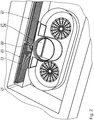
- a part of the flow channel 12 are two fan housing 13.
- the two fan housing 13 are each also part of a fan 14.
- the respective fan 14 has a fan 15 and a fan motor 16.
- the extractor device is designed to convey cooking fumes through the inflow opening 11 along the flow channel 12 and through the two fans 14.
- the flow channel 12 comprises a pressure duct section 17 arranged downstream of the fan 14 and a vacuum duct section 18 arranged upstream of the fan 14 and downstream of the inlet opening 11.
- a filter seat 19 is arranged. At the filter seat 19, two filters 20 are arranged for filtering the cooking fumes.
- the two filters 20 are designed as odor filters.
- a filter exchange space 21 is arranged between the inflow opening 11 and the filter seat 19, a filter exchange space 21 is arranged.
- the filter exchange space 21 is formed such that the filter 20 is reversibly removable through the inflow opening 11.
- the filter exchange space 21 has an inner, free cross section in which the respective filter 20 can be displaced between the filter seat 19 and through the inflow opening 11.
- the filter seat 19 has a flow opening 22, not shown.
- the flow opening 22 is completely flowed through by the cooking fumes.
- the two filters 20 completely cover the flow opening 22.
- the filters 20 are arranged in the flow channel 12 such that the cooking vapor stream flows completely through them.
- the filter seat 19 has a sealing means 23.
- the sealing means 23 is formed as a sealing lip.
- the sealant 23 is made of a rubber elastic material.
- the sealing means 23 completely surrounds the flow opening 22.
- the filter 20 has a sealing surface 24.
- the sealing surface 24 forms a fluid-tight connection together with the sealing means 23.
- the filter 20 may include the sealant 23 and the filter seat 19 may be formed with a sealing surface 24.
- the filter 20 is fluid-tightly connected to the filter seat 19.
- the two filters 20 arranged between the fans 14 and the flow opening 22 are designed to be permeable by cooking fumes.
- Fig. 1 and Fig. 2 the two filters 20 are shown in their arrangement on the filter seat 19.
- a first filter 20 is disposed in the filter exchange space 21 between the filter seat 19 and the inflow opening 11.
- a second filter 20 has already been removed from the extractor device 2 and not shown.
- the filter exchange space 21 has a guide device 25 for guided displacement of the two filters 20.
- the guide device 25 is formed by the walls of the filter seat 19. When introducing the filter 20 into the filter seat 19, these are guided between an upper and a lower wall, and by a flow opening 22 having the rear wall of the filter seat 19.
- the filter exchange space 21 comprises a transport channel 26.
- the transport channel 26 extends between the negative pressure channel section 18 and the overpressure channel section 17. Through the transport channel 26 of the respective filter 20 between the filter seat 19 and the inlet opening 11 is displaced.
- the filter exchange space 21 has a closure flap 27.
- the closure flap 27 is designed to close the filter exchange space 21 in a fluid-tight manner against a flow of cooking fumes.
- the closure flap 27 is articulated to the flow channel 12.
- the closure flap 27 is displaceable between a closure position 28, in which the filter exchange space 21 is closed in a fluid-tight manner, and an open position 29, in which the filter exchange space is open for the reversible removal of the two filters 20.
- the closure flap 27 can be opened in the direction of the vacuum channel section 18. Alternatively, the closure flap 27 can also be opened in the direction of the overpressure channel section 17.
- the control unit 9 is designed to operate the hob 3 and the extractor device 2, in particular the two fans 14.
- the extractor device 2 has a sensor device 30.
- the sensor device 30 comprises a filter sensor 31 for detecting the arrangement of the two filters 20 on the filter seat 19.
- the sensor device 30 is in Signal connection with the control unit 9.
- the control unit 9 is designed to interrupt the operation of the fan 14 based on a signal of the sensor device 30.
- the sensor device 30 is embodied such that a signal for interrupting the operation of the fan 14 is provided, provided that the filter sensor 31 detects a missing and / or incorrect arrangement of the two filters 20 on the filter seat 19.
- the sensor device 30 has a closure flap sensor 32 for detecting an arrangement of the closure flap 27.
- the sensor device 30 is designed to provide a signal for interrupting the operation of the fan 14, provided that the shutter sensor 32 detects an arrangement of the shutter 27 outside the closed position 28.
- the flow opening 22 has a major dimension s F, the major dimension F s is greater than a major dimension E s of the inflow port 11.
- An opening area A F of the flow opening 22 is greater than an inflow area A E of the inflow opening. 11
- the two filters 20 are formed deformable.
- the two filters 20 each have a main extension 33.
- the two filters 20 are integrally formed and stretch-resistant in the direction of the main extension 33.
- To a perpendicular to the main extension 33 oriented axis, the two filters 20 are formed pliable.
- For reversible removal of the respective filter 20 is formed bendable about a vertical axis.
- the extractor device 2 has a drive device 34 for the automated displacement of the two filters 20 in the filter exchange space 21.
- the drive means 34 is adapted to the respective filter 20 along the guide means 25 to the filter seat 19 and to move from the filter seat 19 in the direction of the inflow opening 11.
- the drive device 34 is in correct communication with the filter sensor 31 for positioning the respective filter 20.
- the operation of the hob system 1 is as follows: The hob system 1 is controllable via the control unit 9. User inputs are passed from the user interface 10 to the control unit 9.
- the control unit 9 is in signal communication with the cooking zones 7 and the fan motors 16. The control unit 9 allows the adjustment of the cooking points 7 and the fan motors 16 supplied power.
- the fan motors 16 When the fan motors 16 are supplied with electrical power, a torque is transmitted to the fan wheels 15.
- the rotating fan wheels 15 produce a lower negative pressure in the negative pressure channel section 18 than an ambient pressure and a higher overpressure in the overpressure channel section 17 than the ambient pressure.
- Fig. 1 and Fig. 2 the filters 20 are shown arranged on the filter seat 19.
- the filter sensors 31 detect the arrangement of the filters 20 on the filter seat 19.
- the shutter 27 is in the closed position 28.
- the shutter sensor 32 detects the arrangement of the shutter 27 in the closed position 28. The operation of the two fans 14 and their Supply of electrical power are released.
- the closure flap 27 is arranged in the open position 29.
- the first filter 20 is displaced along the filter exchange space 21 in the direction of the inflow opening 11 and the second filter 20 is already removed from the extractor device 2.
- the filter sensor 31 detects the displacement of the respective filter 20 from the filter seat 19.
- the closure flap sensor 32 detects the arrangement of the closure flap 27 in the open position 29.
- the control unit 9 detects a signal from the sensor device 32 to interrupt the operation of the two fans 14 The operation of the two fan motors 16 is interrupted.
- the removal of the two filters 20 from the filter seat 19 and the insertion into the filter seat 19 is partially automated.
- the drive device 24 is in engagement with the respective filter 20.
- the respective filter 20 is displaced along the guide device 25.
- the filter For removal of the respective filter 20 through the filter exchange space 21 and the inflow opening 11 this is curved about a vertical axis, in particular rolled. In the curved shape, the filter is 20 through the inlet opening 11 from the extractor device removed.
- the respective filter 20 is first deformed, in particular curved about the vertical axis, then introduced through the inflow opening 11 in the negative pressure channel section 18 and along the filter exchange space 21 through the transport channel 26 and from the Guiding device 25 guided displaced to the filter seat 19.
- the displacement of the respective filter 20 is partially automated by actuation of the drive means 34.
- the filter sensors 31 detect the arrangement of the respective filter 20 on the filter seat 19.
- the closure flap 27 is displaced into the closure position 28 and the closure flap sensor 32 detects the arrangement the shutter 27 in the closed position 28. The signal for interrupting the operation of the two fans 14 is canceled and the operation of the two fans 14 can be resumed.
- the extractor device 2 only a fan 14.
- a single filter 20 can be arranged.
- the displacement of the filter 20 within the filter exchange space 21 is completely manual, especially by hand.
- the filter exchange space 21 has a transport channel 26.
- the wall of the transport channel 26 is designed to guide the filter 20 and forms part of the guide device 25.
- the transport channel 26 extends between the vacuum channel section 18 and the overpressure channel section 17.
- the filter exchange space 21 by means of the flap 27 is reversibly closed.
- the extractor device 2 has a fan 14 and a filter 20 which can be arranged on the filter seat 19, wherein the transport channel 26 is designed to be simply curved.
- the closure flap 27 is arranged on the part of the overpressure channel section 17 of the transport channel 26.
- the closure flap 27 can be actuated by the drive device 34.
- the drive device 34 is designed to displace the filter 20 along the filter exchange space 21.
- the flow opening 22 is flat.
- a program for removing the filter 20 in the control unit 9 is activated via the user interface 10.
- the closure flap 27 is displaced from the closed position 28 into the open position 29 by means of the drive device 34.
- the filter 20 is then displaced along the transport channel 26 through the filter exchange space 21 into the negative pressure channel section 18. The filter 20 can then be removed by hand from the inflow opening 11.
- Fig. 9 another embodiment of the invention is described.
- the fan 15 of the fan 14 is arranged centrally below the inlet opening 11.
- the fan 15 is dimensioned such that it can be removed from the inflow opening 11.
- the filter exchange space 21 is formed by the flow channel 12.
- the fan 15 is first removed from the flow channel 12 through the inlet opening 11.
- the filter replacement space 21 formed by the flow channel 12 is released to such an extent that the filter 20 can be removed from the filter seat 19 through the inflow opening 11.
- the extractor device 2 according to this embodiment has no transport channel 26 and a closure flap 27 is not necessary.
- the embodiment according to Fig. 9 underlying features are arbitrarily combined with those of the previous embodiments.
- the flow opening 22 is formed curved.
- the filter 20 is disposed on the filter seat 19 in a curved shape.
- the filter exchange space 21 comprises the transport channel 26 and can be closed by means of the closure flap 27 against flowing through cooking fumes.
- a guide means 25 is arranged in the form of a slide guide in the filter change space 21.
- the filter exchange space 21 has a groove in which a frame of the filter 20 is at least partially linearly displaceably mounted.
- the filter seat is flat.
- the filter 20 is displaced along the slotted guide, wherein first an end of the filter 20 facing the inflow opening 11 is curved.
- the filter 20 is hereafter in the in Fig. 10 position shown.
- the filter 20 is displaced further along the slotted guide in the direction of the inflow opening 11.
Abstract
Die Erfindung betrifft eine Dunstabzugsvorrichtung (2) zum Abzug von Kochdünsten nach unten. Die Dunstabzugsvorrichtung (2) umfasst mindestens einen Lüfter (14) zum Ansaugen der Kochdünste, eine Einströmöffnung (11) zum Eintritt der Kochdünste in die Dunstabzugsvorrichtung (2), einen stromabwärts des mindestens einen Lüfters (14) angeordneten Filtersitz (19), an dem mindestens ein Filter (20) zum Filtern der Kochdünste anordenbar ist und einen sich zwischen der Einströmöffnung (11) und dem mindestens einen Filtersitz (19) erstreckenden Filterwechselraum (21), wobei der Filterwechselraum (21) zum reversiblen Entnehmen des mindestens einen Filters (20) aus dem Filtersitz (19) durch die Einströmöffnung (11) ausgebildet ist.

Description
Die vorliegende Erfindung nimmt die Priorität der deutschen Patentanmeldungen
Die Erfindung betrifft eine Dunstabzugsvorrichtung. Ferner richtet sich die Erfindung auf einen Filter für eine Dunstabzugsvorrichtung sowie auf ein Kochfeldsystem.The invention relates to a fume extraction device. Furthermore, the invention is directed to a filter for a fume extraction device and to a hob system.
Aus der
Es ist eine Aufgabe der Erfindung, eine Dunstabzugsvorrichtung zu verbessern.It is an object of the invention to improve a fume extractor.
Diese Aufgabe wird durch eine Dunstabzugsvorrichtung mit den Merkmalen des Anspruchs 1 gelöst. Erfindungsgemäß wurde erkannt, dass der sich zwischen dem stromabwärts des Lüfters angeordneten Filtersitz und der Einströmöffnung erstreckende Filterwechselraum derart ausgebildet sein kann, dass der mindestens eine Filter aus dem Filtersitz durch die Einströmöffnung reversibel entnehmbar ist. Durch die Zugänglichkeit der Einströmöffnung und damit des Filters von einem Bereich oberhalb der Dunstabzugsvorrichtung entfällt eine aufwändige und für den Benutzer komplizierte Entnahme über einen Unterraum der Dunstabzugsvorrichtung. Die reversible Entnehmbarkeit des Filters durch die Einströmöffnung gewährleistet, dass eine an die Einströmöffnung angrenzende Fläche, insbesondere eine Oberseite eines Kochfeldes, von zusätzlichen Entnahmeöffnungen freigehalten wird. Die Oberseite des Kochfeldes steht somit zur Erwärmung von Kochgut zur Verfügung. Auf eine zusätzliche Abdichteinrichtung zum Schutz derartiger Entnahmeöffnungen vor übergelaufenen Flüssigkeiten kann verzichtet werden. Eine strukturelle Schwächung des Kochfeldes durch Einbringen zusätzlicher Entnahmeöffnungen unterbleibt. Die Abzugsvorrichtung weist insgesamt ein schlichtes und aufgeräumtes Erscheinungsbild auf.This object is achieved by a fume extractor with the features of claim 1. According to the invention, it was recognized that the between the downstream of the fan arranged filter seat and the inflow opening extending filter exchange space may be formed such that the at least one filter is reversibly removed from the filter seat through the inflow opening. Due to the accessibility of the inflow opening and thus of the filter from an area above the extractor device eliminates a complex and complicated for the user removal via a subspace of the extractor device. The reversible removability of the filter through the inflow opening ensures that a surface adjoining the inflow opening, in particular an upper side of a hob, is kept free from additional removal openings. The top of the hob is thus available for heating food. An additional sealing device for protecting such removal openings from overflowed liquids can be dispensed with. A structural weakening of the hob by introducing additional removal openings is omitted. The trigger device has a total of a simple and tidy appearance.
Der Filterwechselraum stellt eine räumliche Verbindung zwischen der Einströmöffnung und dem Filtersitz her. In dem Filterwechselraum ist der mindestens eine Filter zwischen dem Filtersitz und der Einströmöffnung verlagerbar. Hierzu weist der Filterwechselraum an jeder Stelle einen inneren freien Querschnitt auf, der größer ist als ein Querschnitt des mindesten einen Filters. Der Filterwechselraum kann, insbesondere abschnittsweise, durch einen Strömungskanal zum Führen der Kochdünste ausgebildet sein. Vorteilhaft wird hierdurch erreicht, dass zur Ausbildung des Filterwechselraums auf zusätzliche Strukturen verzichtet werden kann. Alternativ kann der Filterwechselraum, insbesondere abschnittsweise, außerhalb des Strömungskanals ausgebildet sein.The filter exchange space establishes a spatial connection between the inflow opening and the filter seat. In the filter exchange space, the at least one filter is displaceable between the filter seat and the inflow opening. For this purpose, the filter exchange space at each point on an inner free cross section which is greater than a cross section of the at least one filter. The filter exchange space can, in particular sections, be formed by a flow channel for guiding the cooking fumes. Advantageously, this achieves that it is possible to dispense with additional structures to form the filter exchange space. Alternatively, the filter exchange space, in particular sections, be formed outside the flow channel.
Vorzugsweise ist der Filter stromaufwärts des Filtersitzes angeordnet. Durch die Anordnung des Filters stromaufwärts des Filtersitzes drückt der Kochdunststrom den Filter beim Betrieb der Dunstabzugsvorrichtung gegen den Filtersitz. Hierdurch ist der Filter besonders fest, insbesondere dicht, an dem Filtersitz anbringbar.Preferably, the filter is disposed upstream of the filter seat. Due to the arrangement of the filter upstream of the filter seat, the cooking vapor stream presses the filter during operation of the extractor device against the filter seat. As a result, the filter is particularly strong, in particular tight, attachable to the filter seat.
Gemäß einem Aspekt der Erfindung weist die Dunstabzugsvorrichtung eine Einströmöffnung zum Eintritt der Kochdünste in die Dunstabzugsvorrichtung auf. Hierunter ist zu verstehen, dass die erfindungsgemäße Dunstabzugsvorrichtung mindestens eine Einströmöffnung aufweist. Die Dunstabzugsvorrichtung kann auch mindestens zwei, insbesondere mindestens drei, insbesondere mindestens vier Einströmöffnungen aufweisen. Die Einströmöffnung ist vorzugsweise rund, insbesondere kreisförmig oder nichtkreisförmig, insbesondere oval, oder in Form eines Vielecks, insbesondere in Form eines Rechtecks, insbesondere in Form eines Quadrats, ausgebildet.According to one aspect of the invention, the extractor device has an inflow opening for the entry of the cooking fumes into the extractor device. This is understood to mean that the extractor device according to the invention has at least one inflow opening. The extractor device may also have at least two, in particular at least three, in particular at least four inflow openings. The inflow opening is preferably round, in particular circular or non-circular, in particular oval, or in the form of a polygon, in particular in the form of a rectangle, in particular in the form of a square formed.
Gemäß einem Aspekt der Erfindung weist die Dunstabzugsvorrichtung mindestens einen Lüfter auf. Die Dunstabzugsvorrichtung kann auch mindestens zwei, insbesondere mindestens drei, insbesondere mindestens vier, Lüfter aufweisen. Der mindestens eine Lüfter kann in einer Draufsicht beabstandet zu einem geometrischen Flächenschwerpunkt der Einströmöffnung angeordnet sein. Alternativ kann der mindestens eine Lüfter konzentrisch zu der Einströmöffnung angeordnet sein. Vorteilhaft wird durch die konzentrische Anordnung des Lüfters gegenüber der Einströmöffnung erreicht, dass Kochdünste strömungsmechanisch besonders effizient angesaugt werden. Eine Drehachse des mindestens einen Lüfters kann horizontal oder vertikal orientiert sein.According to one aspect of the invention, the extractor device has at least one fan. The extractor device may also have at least two, in particular at least three, in particular at least four, fans. The at least one fan may be arranged in a plan view spaced apart from a geometric centroid of the inflow opening. Alternatively, the at least one fan may be arranged concentrically with the inflow opening. Advantageously, it is achieved by the concentric arrangement of the fan with respect to the inflow opening that boiling fumes are sucked in particularly fluidically. An axis of rotation of the at least one fan can be oriented horizontally or vertically.
An dem Filtersitz ist der mindestens eine Filter anordenbar. Vorzugsweise sind an dem Filtersitz mindestens zwei, insbesondere mindestens drei, insbesondere mindestens vier, insbesondere mindestens fünf, Filter anordenbar. Durch die Anordnung mehrerer Filter an dem Filtersitz kann die Filterfläche und/oder eine Strömungsöffnung des Filtersitzes vergrößert werden, wobei die reversible Entnehmbarkeit des mindestens einen Filters aus dem Filtersitz durch die Einströmöffnung erhalten bleibt. Vorzugsweise sind die mindestens zwei Filter, insbesondere fluiddicht, aneinander anbringbar ausgebildet.At least one filter can be arranged on the filter seat. Preferably, at least two, in particular at least three, in particular at least four, in particular at least five, filters can be arranged on the filter seat. By arranging a plurality of filters on the filter seat, the filter surface and / or a flow opening of the filter seat can be increased, wherein the reversible removability of the at least one filter from the filter seat is maintained by the inflow opening. Preferably, the at least two filters, in particular fluid-tight, are designed to be attached to one another.
Vorzugsweise ist der mindestens eine Filter manuell, insbesondere händisch und/oder werkzeuglos, aus dem Filtersitz durch die Einströmöffnung, entnehmbar. Hierzu können der Filterwechselraum und/oder der Filtersitz entsprechend ausgebildet sein.Preferably, the at least one filter can be removed manually, in particular by hand and / or without tools, from the filter seat through the inflow opening. For this purpose, the filter exchange space and / or the filter seat can be designed accordingly.
Gemäß einem Aspekt der Erfindung ist der mindestens eine Filter in einem Überdruck-Kanalabschnitt angeordnet. Unter dem Überdruck-Kanalabschnitt wird der stromabwärts des mindestens einen Lüfters gelegene Abschnitt des Strömungskanals verstanden. Vorteilhaft wird hierdurch erreicht, dass der Strömungswiderstand des mindestens einen Filters einen geringeren Einfluss auf die Abzugsleistung der Dunstabzugsvorrichtung hat, als ein in einem Unterdruck-Kanalabschnitt angeordneter Filter. Unter dem Unterdruck-Kanalabschnitt wird der stromaufwärts des mindestens einen Lüfters gelegene Abschnitt des Strömungskanals verstanden. Zudem werden durch die reversible Entnehmbarkeit des Filters durch die Einströmöffnung ein regelmäßiger Filterwechsel und/oder eine Filterreinigung gefördert. Hierdurch kann der Strömungswiderstand des Filters reduziert und die Funktion der Dunstabzugsvorrichtung aufrechterhalten werden.According to one aspect of the invention, the at least one filter is arranged in an overpressure channel section. The overpressure channel section is understood as the section of the flow channel located downstream of the at least one fan. Advantageously, it is thereby achieved that the flow resistance of the at least one filter has a smaller influence on the withdrawal rate of the extractor device than a filter arranged in a negative pressure channel section. The negative-pressure channel section is understood as the section of the flow channel located upstream of the at least one fan. In addition, by the reversible removability of the filter through the inflow opening a regular filter change and / or a filter cleaning promoted. As a result, the flow resistance of the filter can be reduced and the function of the extractor device can be maintained.
Gemäß einem Aspekt der Erfindung ist in dem Filterwechselraum eine Führungseinrichtung zum geführten Verlagern des mindestens einen Filters angeordnet. Die Führungseinrichtung kann durch eine Wandung des Filterwechselraums ausgebildet sein. Vorzugsweise ist die Führungseinrichtung zur linearen Lagerung des mindestens einen Filters ausgebildet. Bei der linearen Lagerung kann die Verlagerung ausschließlich entlang einer Linie erfolgen. Die Führungseinrichtung kann zusammen mit dem mindestens einen Filter eine Nut-Feder-Verbindung und/oder eine Kulissenführung ausbilden. Die Führungseinrichtung kann auch in Form eines Kanals ausgebildet sein, in dem der mindestens eine Filter linear verschiebbar gelagert ist. Vorteilhaft wird hierdurch erreicht, dass der mindestens eine Filter zuverlässig, insbesondere ohne ein Verkanten, aus dem Filtersitz entnehmbar ist.According to one aspect of the invention, a guide device for guided displacement of the at least one filter is arranged in the filter exchange space. The guide device can be formed by a wall of the filter exchange space. Preferably, the guide device is designed for the linear mounting of the at least one filter. In the case of linear storage, the displacement can take place exclusively along one line. The guide device can form together with the at least one filter a tongue and groove connection and / or a sliding guide. The guide device can also be designed in the form of a channel in which the at least one filter is mounted linearly displaceable. This advantageously achieves the effect that the at least one filter can be removed from the filter seat reliably, in particular without jamming.
Gemäß einem Aspekt der Erfindung weist der Filtersitz ein Dichtmittel und/oder eine Dichtfläche zum fluiddichten Verbinden mit dem mindestens einen Filter auf. Vorzugsweise umgibt das Dichtmittel die Strömungsöffnung des Filtersitzes vollständig. Das Dichtmittel kann dazu ausgebildet sein, mit einer Dichtfläche des mindestens einen Filters zusammenzuwirken. Alternativ kann auch der Filtersitz die Dichtfläche und der mindestens eine Filter das Dichtmittel aufweisen. Durch die fluiddichte Anbindung des mindestens einen Filters an den Filtersitz wird gewährleistet, dass der gesamte Kochdunststrom durch den mindestens einen Filter hindurchgeführt wird und diesen nicht umströmt.According to one aspect of the invention, the filter seat has a sealing means and / or a sealing surface for fluid-tight connection to the at least one filter. Preferably, the sealing means completely surrounds the flow opening of the filter seat. The sealing means may be designed to cooperate with a sealing surface of the at least one filter. Alternatively, the filter seat can also have the sealing surface and the at least one filter can have the sealing means. The fluid-tight connection of the at least one filter to the filter seat ensures that the entire cooking vapor stream is passed through the at least one filter and does not flow around it.
Gemäß einem weiteren Aspekt der Erfindung ist in dem Filterwechselraum ein Transportkanal angeordnet, durch den hindurch der mindestens eine Filter verlagerbar ist. Der Transportkanal kann sich zwischen dem Unterdruck-Kanalabschnitt und dem Filtersitz erstrecken. Der Transportkanal ist vorzugsweise außerhalb des mindestens einen Lüfters angeordnet. Vorteilhaft ermöglicht der Transportkanal eine besonders kurze Verbindung zwischen dem Filtersitz und dem Unterdruck-Kanalabschnitt. Die Länge des Transportkanals ist vorzugsweise geringer als 200 mm, insbesondere geringer als 150 mm, insbesondere geringer als 100 mm, insbesondere geringer als 70 mm, insbesondere geringer als 50 mm, insbesondere geringer als 25 mm, insbesondere geringer als 10 mm. Hierdurch wird die reversible Entnahme des Filters aus dem Filtersitz ermöglicht, ohne dass dieser durch ein Lüfter-Gehäuse des Lüfters geführt werden muss.According to a further aspect of the invention, a transport channel is arranged in the filter exchange space through which the at least one filter is displaceable. The transport channel may be between the negative pressure channel section and the filter seat. The transport channel is preferably arranged outside the at least one fan. Advantageously, the transport channel allows a particularly short connection between the filter seat and the vacuum channel section. The length of the transport channel is preferably less than 200 mm, in particular less than 150 mm, in particular less than 100 mm, in particular less than 70 mm, in particular less than 50 mm, in particular less than 25 mm, in particular less than 10 mm. As a result, the reversible removal of the filter is made possible from the filter seat, without this must be performed by a fan housing of the fan.
Vorzugsweise ist der Transportkanal fluiddicht ausgebildet und fluiddicht an den Unterdruck-Kanalabschnitt und den Überdruck-Kanalabschnitt angeschlossen. Vorteilhaft wird hierdurch erreicht, dass sowohl der Unterdruck-Kanalabschnitt als auch der Überdruck-Kanalabschnitt gegenüber der Umgebung fluiddicht ausgeführt sind.Preferably, the transport channel is formed fluid-tight and fluid-tightly connected to the negative pressure channel portion and the overpressure channel section. Advantageously, this ensures that both the negative pressure channel section and the overpressure channel section are designed to be fluid-tight with respect to the environment.
Gemäß einem weiteren Aspekt der Erfindung ist in dem Filterwechselraum eine Verschlussklappe zum reversiblen Verschließen gegen eine Durchströmung mit den Kochdünsten angeordnet. Vorzugsweise ist die Verschlussklappe dazu ausgebildet, einen mit dem Überdruck-Kanalabschnitt verbundenen Abschnitt des Filterwechselraums fluiddicht von einem mit dem Überdruck-Kanalabschnitt verbundenen Abschnitt des Filterwechselraums zu trennen. Vorzugsweise ist die Verschlussklappe zum Verschluss des Transportkanals ausgebildet. Die Verschlussklappe kann innerhalb des Transportkanals oder an einem der beiden Enden des Transportkanals angeordnet sein. Es kann auch an je einem Ende des Transportkanals eine Verschlussklappe angeordnet sein. Die Verschlussklappe kann zwischen einer Verschlussstellung und einer Offenstellung verlagerbar sein. Die Verschlussklappe kann beispielsweise als gelenkig gelagerte Klappe oder als verschiebbar gelagerte Scheibe ausgebildet sein. Der mindestens eine Filter kann in der Offenstellung reversibel aus dem Filtersitz entnehmbar sein. Vorteilhaft wird hierdurch erreicht, dass in der Verschlussstellung kein Druckausgleich zwischen dem Überdruck-Kanalabschnitt und dem Unterdruck-Kanalabschnitt erfolgen kann.According to a further aspect of the invention, a closure flap for reversibly closing against a flow with the cooking fumes is arranged in the filter exchange space. Preferably, the closure flap is designed to fluid-tightly separate a portion of the filter exchange space connected to the overpressure passage section from a section of the filter change space connected to the overpressure passage section. Preferably, the closure flap is designed to close the transport channel. The closure flap can be arranged within the transport channel or at one of the two ends of the transport channel. It can also be arranged at each end of the transport channel a closure flap. The closure flap can be displaceable between a closed position and an open position. The flap may be formed, for example, as a hinged flap or slidably mounted disc. The at least one filter can be reversibly removed from the filter seat in the open position. This advantageously achieves that in the closed position no pressure compensation between the overpressure channel section and the negative pressure channel section can take place.
Vorzugsweise wird die Verschlussklappe bei einer Verlagerung in die Offenstellung in Richtung des Überdruck-Kanalabschnitts bewegt. Hierdurch wird erreicht, dass ein Druckunterschied zwischen dem Überdruck-Kanalabschnitt und dem Unterdruck-Kanalabschnitt das Schließen der Verschlussklappe im Betrieb der Dunstabzugsvorrichtung begünstigt.Preferably, the shutter is moved in a shift into the open position in the direction of the overpressure channel section. As a result, it is achieved that a pressure difference between the overpressure channel section and the negative pressure channel section favors the closure of the closure flap during operation of the extractor device.
Gemäß einem weiteren Aspekt der Erfindung weist die Dunstabzugsvorrichtung eine Steuereinheit zum Betreiben des mindestens einen Lüfters auf. Die Dunstabzugsvorrichtung kann eine mit der Steuereinheit in Signalverbindung stehende Sensoreinrichtung aufweisen. Vorzugsweise ist die Steuereinheit zum Unterbrechen des Betriebs des mindestens einen Lüfters anhand eines Signals der Steuereinrichtung ausgebildet. Vorteilhaft wird hierdurch erreicht, dass der Betrieb des mindestens einen Lüfters unterbrochen werden kann, sofern eine Gefahr für einen Nutzer besteht und/oder die Dunstabzugsvorrichtung nicht betriebsbereit ist.According to a further aspect of the invention, the extractor device has a control unit for operating the at least one fan. The extractor device may have a sensor device in signal connection with the control unit. Preferably, the control unit is designed to interrupt the operation of the at least one fan based on a signal of the control device. Advantageously, this achieves the result that the operation of the at least one fan can be interrupted if there is a risk for a user and / or the extractor device is not ready for operation.
Gemäß einem weiteren Aspekt der Erfindung weist die Sensoreinrichtung einen Filter-Sensor zum Erfassen einer Anordnung des mindestens einen Filters an dem Filtersitz auf. Der Filter-Sensor kann als Endanschlag-Sensor, insbesondere als Druckschalter oder als Magnetschalter, oder in Form einer Lichtschranke, ausgebildet sein. Durch das Erfassen der Anordnung des mindestens einen Filters an dem Filtersitz wird gewährleistet, dass die Steuereinheit anhand eines Signals der Sensoreinrichtung den Betrieb des mindestens einen Lüfters bei fehlender und/oder falscher Anordnung des mindestens einen Filters an dem Filtersitz unterbrechen kann.According to a further aspect of the invention, the sensor device has a filter sensor for detecting an arrangement of the at least one filter on the filter seat. The filter sensor can be designed as an end stop sensor, in particular as a pressure switch or as a magnetic switch, or in the form of a light barrier. By detecting the arrangement of the at least one filter on the filter seat is ensured that the control unit based on a signal of the sensor device can interrupt the operation of the at least one fan in the event of missing and / or incorrect arrangement of the at least one filter on the filter seat.
Gemäß einem Aspekt der Erfindung umfasst die Sensoreinrichtung einen Verschlussklappen-Sensor zum Erfassen einer Anordnung der Verschlussklappe. Vorzugsweise ist der Verschlussklappen-Sensor als Taster oder als Kippschalter oder als Magnetschalter oder als induktiver Schalter oder als kapazitiver Schalter oder in Form einer Lichtschranke ausgebildet. Vorteilhaft wird hierdurch erreicht, dass die Steuereinheit aufgrund eines Signals der Sensoreinrichtung den Betrieb des mindestens einen Lüfters bei einer Anordnung der Verschlussklappe in der Offenstellung unterbrechen kann.According to one aspect of the invention, the sensor device comprises a closure flap sensor for detecting an arrangement of the closure flap. Preferably, the closure flap sensor is designed as a push-button or as a toggle switch or as a magnetic switch or as an inductive switch or as a capacitive switch or in the form of a light barrier. Advantageously, this ensures that the control unit can interrupt the operation of the at least one fan in an arrangement of the closure flap in the open position on the basis of a signal of the sensor device.
Gemäß einem weiteren Aspekt der Erfindung weist die Strömungsöffnung des Filtersitzes eine Hauptabmessung auf, welche größer ist als eine Hauptabmessung der Einströmöffnung. Der Strömungsquerschnitt des Strömungskanals kann somit im Bereich des mindestens einen Filters relativ zu einer Hauptabmessung der Einströmöffnung besonders groß ausgebildet sein. Vorteilhaft wird hierdurch erreicht, dass das Verhältnis zwischen Filterwirkung und Druckverlust besonders groß ist, wobei die Dunstabzugsvorrichtung besonders effizient betrieben werden kann.According to a further aspect of the invention, the flow opening of the filter seat has a main dimension which is greater than a main dimension of the inflow opening. The flow cross-section of the flow channel can thus be designed to be particularly large in the region of the at least one filter relative to a main dimension of the inflow opening. Advantageously, this achieves the result that the ratio between filter effect and pressure loss is particularly high, wherein the extractor device can be operated particularly efficiently.
Vorzugsweise beträgt das Verhältnis zwischen der Hauptabmessung der Strömungsöffnung und der Hauptabmessung der Einströmöffnung mindestens 1, insbesondere mindestens 1,2, insbesondere mindestens 1,5, insbesondere mindestens 2, insbesondere mindestens 2,5, insbesondere mindestens 3.The ratio between the main dimension of the flow opening and the main dimension of the inflow opening is preferably at least 1, in particular at least 1.2, in particular at least 1.5, in particular at least 2, in particular at least 2.5, in particular at least 3.
Gemäß einem weiteren Aspekt der Erfindung ist eine Öffnungsfläche der Strömungsöffnung größer als eine Einströmfläche der Einströmöffnung. Vorzugsweise beträgt das Verhältnis zwischen der Öffnungsfläche und der Einströmöffnung mindestens 1, insbesondere min 1,5, insbesondere mindestens 2, insbesondere mindestens 2,5, insbesondere mindestens 3. Vorteilhaft wird hierdurch erreicht, dass das Verhältnis zwischen einer Filterwirkung des mindestens einen Filters und einem Druckverlust über den mindestens einen Filter besonders hoch ist.According to a further aspect of the invention, an opening area of the flow opening is larger than an inflow area of the inflow opening. Preferably, the ratio between the opening area and the inflow opening is at least 1, in particular at least 1.5, in particular at least 2, in particular at least 2.5, in particular at least 3. It is advantageously achieved that the ratio between a filtering effect of the at least one filter and a Pressure loss over the at least one filter is particularly high.
Gemäß einem weiteren Aspekt der Erfindung weist die Dunstabzugsvorrichtung eine Antriebseinrichtung zum zumindest teilweise automatisierten Verlagern des mindestens einen Filters in dem Filterwechselraum auf. Die Antriebseinrichtung kann einen Antriebsmotor und ein Antriebsgetriebe aufweisen. Vorzugsweise steht die Antriebseinrichtung, insbesondere das Antriebsgetriebe, in Eingriff mit dem mindestens einen Filter. Der mindestens eine Filter kann hierzu einen Antriebs-Eingriff aufweisen. Vorzugsweise ist die Antriebseinrichtung zum Verlagern des mindestens einen Filters an den Filtersitz ausgebildet. Hierdurch kann eine besonders exakte Positionierung des mindestens einen Filters an dem Filtersitz erreicht werden. Vorzugsweise wird der mindestens eine Filter zunächst manuell, insbesondere von Hand, in den Filterwechselraum eingebracht, bevor der mindestens eine Filter mittels der Antriebseinrichtung an den Filtersitz verlagert wird.According to a further aspect of the invention, the extractor device has a drive device for at least partially automated displacement of the at least one filter in the filter change space. The drive device may comprise a drive motor and a drive gear. The drive device, in particular the drive gear, is preferably in engagement with the at least one filter. The at least one filter can have a drive engagement for this purpose. Preferably, the drive device is designed for displacing the at least one filter to the filter seat. As a result, a particularly exact positioning of the at least one filter on the filter seat can be achieved. Preferably, the at least one filter is first manually, in particular by hand, introduced into the filter exchange space before the at least one filter is displaced by means of the drive means to the filter seat.
Die Antriebseinrichtung kann mit dem mindestens einen Filter über ein Zahnrad oder einen Riemen, insbesondere einen Zahnriemen, oder einen Linearantrieb in Verbindung stehen.The drive device may be in communication with the at least one filter via a toothed wheel or a belt, in particular a toothed belt, or a linear drive.
Im Folgenden sind weitere Merkmale der erfindungsgemäßen Dunstabzugsvorrichtung angeführt. Welche frei mit den bislang genannten Merkmalen kombinierbar sind.In the following, further features of the extractor device according to the invention are given. Which can be freely combined with the features mentioned so far.
Der mindestens eine Lüfter kann als Radial-Lüfter beziehungsweise als Zentrifugal-Lüfter oder als Axial-Lüfter ausgebildet sein. Vorzugsweise weist die Dunstabzugsvorrichtung zwischen der Einströmöffnung und einer Unterseite des Unterdruck-Kanalabschnitts und/oder einer Unterseite des mindestens einen Lüfters eine Bauhöhe von höchstens 250 mm, insbesondere höchstens 220 mm, insbesondere höchstens 200 mm, insbesondere höchstens 175 mm, insbesondere höchstens 150 mm auf.The at least one fan can be configured as a radial fan or as a centrifugal fan or as an axial fan. Preferably, the extractor device between the inflow opening and a bottom of the vacuum duct section and / or a bottom of the at least one fan has a height of at most 250 mm, in particular at most 220 mm, in particular at most 200 mm, in particular at most 175 mm, in particular at most 150 mm ,
Eine weitere Aufgabe der Erfindung besteht darin, einen Filter zu verbessern.Another object of the invention is to improve a filter.
Diese Aufgabe wird durch einen reversibel verformbaren Filter für eine Dunstabzugsvorrichtung gelöst. Unter der reversiblen Verformbarkeit wird verstanden, dass es bei dem Verformen nicht zu einem mechanischen Versagen des Filters kommt. Vorzugsweise ist der Filter rein elastisch reversibel verformbar. Der Filter kann als Geruchsfilter ausgebildet sein. Der Filter kann auch als Fettfilter und/oder als Feuchtigkeitsfilter ausgebildet sein. Der Filter kann in Richtung seiner Hauptabmessung dehnbar ausgebildet sein. Der Filter kann auch um seine Mittel-Längs-Achse torsionsweich ausgebildet sein. Der Filter kann um wenigstens eine quer zu der Hauptabmessung verlaufende Achse biegeweich ausgebildet sein. Vorzugsweise ist der Filter einrollbar ausgebildet. Der Filter kann mindestens zwei reversibel aneinander anbringbare Filtersegmente aufweisen. Vorzugsweise sind die mindestens zwei Filtersegmente gelenkig aneinander angebracht und/oder zueinander verlagerbar, insbesondere mit einem Band und/oder einer Schnur, verbunden. Die segmentierte Ausbildung des Filters gewährleistet die einfache und störungsfreie Entnahme des Filters aus dem Filtersitz der Dunstabzugsvorrichtung.This object is achieved by a reversibly deformable filter for a fume extraction device. By reversible deformability it is meant that deformation does not result in mechanical failure of the filter. Preferably, the filter is purely elastically reversible deformable. The filter can be designed as an odor filter. The filter may also be designed as a grease filter and / or as a moisture filter. The filter may be made stretchable in the direction of its main dimension. The filter may also be formed torsionally soft about its central longitudinal axis. The filter may be designed to be bendable around at least one axis extending transversely to the main dimension. Preferably, the filter is formed rollable. The filter may have at least two reversibly attachable filter segments. Preferably, the at least two filter segments are hingedly attached to each other and / or displaced to each other, in particular with a belt and / or a string, connected. The segmented design of the filter ensures easy and trouble-free removal of the filter from the filter seat of the extractor device.
Der Filter kann biegeweich ausgebildet sein. Der Filter kann einen flexiblen, insbesondere biegeweichen, Filterrahmen aufweisen. Der Filterrahmen ist vorzugsweise in einer neutralen Faser des Filters angeordnet. Durch die Anordnung des Filterrahmens in der neutralen Faser des Filters ändert sich die Länge des Filterrahmens aufgrund der Verformung des Filters im Wesentlichen nicht. Der Filterrahmen kann dabei biegeweich ausgebildet sein.The filter can be designed to be flexible. The filter may have a flexible, in particular flexible, filter frame. The filter frame is preferably arranged in a neutral fiber of the filter. Due to the arrangement of the filter frame in the neutral fiber of the filter, the length of the filter frame does not substantially change due to the deformation of the filter. The filter frame can be designed to be flexible.
Alternativ ist der Filter torsionsweich und/oder dehnbar ausgebildet. Der Filterrahmen kann dabei in der neutralen Faser oder im Bereich einer kleinsten konvexen Hüllfläche des Filters oder dazwischen angeordnet sein.Alternatively, the filter is formed torsionally soft and / or stretchable. The filter frame can be arranged in the neutral fiber or in the region of a smallest convex envelope surface of the filter or in between.
Der Filter kann mindestens eine Faltung aufweisen. Vorzugsweise ist der Filter plissiert. Der Filter kann hierdurch verformbar ausgebildet sein. Die Faltung kann auch zu einer Erhöhung der Oberfläche des Filters führen. Die Effektivität des Filters kann hierdurch verbessert werden.The filter may have at least one fold. Preferably, the filter is pleated. The filter can thereby be formed deformable. The folding can also lead to an increase in the surface of the filter. The effectiveness of the filter can thereby be improved.
Vorzugsweise ist der Filter zwischen einer ersten und einer zweiten Filterform verlagerbar. In der ersten Filterform kann eine Hauptabmessung des Filters größer sein als in der zweiten Filterform. Vorzugsweise beträgt ein Verhältnis zwischen den Hauptabmessungen des Filters in der ersten und der zweiten Filterform mindestens 1,2, insbesondere mindestens 1,5, insbesondere mindestens 2, insbesondere mindestens 3, insbesondere mindestens 4.Preferably, the filter is displaceable between a first and a second filter shape. In the first filter form, one major dimension of the filter may be larger than in the second filter shape. Preferably, a ratio between the main dimensions of the filter in the first and the second filter form is at least 1.2, in particular at least 1.5, in particular at least 2, in particular at least 3, in particular at least 4.
Der Filter kann auch um eine Achse quer zu seiner Längsachse biegeweich ausgebildet sein. Vorzugsweise ist der Filter um diese Achse um mindestens 10°, insbesondere mindestens 20°, insbesondere mindestens 30°, insbesondere mindestens 45°, insbesondere mindestens 60° biegbar.The filter may also be designed to be bendable about an axis transverse to its longitudinal axis. Preferably, the filter is bendable about this axis by at least 10 °, in particular at least 20 °, in particular at least 30 °, in particular at least 45 °, in particular at least 60 °.
Gemäß einem Aspekt der Erfindung weist der mindestens eine Filter ein Betätigungsmittel auf. Das Betätigungsmittel kann als Griff zur manuellen, insbesondere zur händischen, Entnahme aus der Dunstabzugsvorrichtung ausgebildet sein. Das Betätigungsmittel kann auch als Band oder als Schnur ausgebildet sein. Hierdurch wird die reversible Entnahme des Filters erleichtert.According to one aspect of the invention, the at least one filter has an actuating means. The actuating means can be designed as a handle for manual, in particular for manual, removal from the extractor device. The actuating means may also be designed as a band or a cord. This facilitates the reversible removal of the filter.
Gemäß einem Aspekt der Erfindung umfasst die Dunstabzugsvorrichtung mindestens einen derartigen Filter. Vorzugsweise ist die Hauptabmessung des Filters größer ist als die Hauptabmessung der Einströmöffnung. Vorzugsweise beträgt das Verhältnis zwischen der Hauptabmessung des Filters und der Hauptabmessung der Einströmöffnung mindestens 1, insbesondere mindestens 1,2, insbesondere mindestens 1,5, insbesondere mindestens 2, insbesondere mindestens 3, insbesondere mindestens 4. Der Strömungsquerschnitt des Filters kann größer sein als die Einströmfläche.According to one aspect of the invention, the extractor device comprises at least one such filter. Preferably, the main dimension of the filter is greater than the main dimension of the inflow opening. Preferably, the ratio between the main dimension of the filter and the main dimension of the inflow opening is at least 1, in particular at least 1.2, in particular at least 1.5, in particular at least 2, in particular at least 3, in particular at least 4. The flow cross section of the filter can be greater than that inflow.
Eine weitere Aufgabe der Erfindung besteht darin, ein Kochfeldsystem zu verbessern.Another object of the invention is to improve a hob system.
Diese Aufgabe wird durch ein Kochfeldsystem mit mindestens einer Dunstabzugsvorrichtung gemäß der vorhergehenden Beschreibung sowie mindestens einem Kochfeld zum Erwärmen von Kochgut gelöst. Die Vorteile ergeben sich aus denen der Dunstabzugsvorrichtung.This object is achieved by a cooktop system with at least one extractor device according to the preceding description and at least one hob for heating cooking product. The advantages arise from those of the extractor device.
Vorzugsweise weist das Kochfeld mindestens eine, insbesondere mindestens zwei, insbesondere mindestens drei, insbesondere mindestens vier, insbesondere mindestens sechs, Kochstellen auf. Die mindestens eine Kochstelle kann als Wärmestrahlungs-Kochstelle und/oder als Induktions-Kochstelle und/oder als Gas-Kochstelle und/oder als Elektro-Masse-Kochstelle ausgebildet sein. Das Kochfeld umfasst mindestens eine Kochstellenplatte und/oder einen Energieüberträger je Kochstelle.Preferably, the hob has at least one, in particular at least two, in particular at least three, in particular at least four, in particular at least six, hotplates. The at least one hotplate can be designed as a heat radiating hotplate and / or as an induction hotplate and / or as a gas hotplate and / or as an electric mass hotplate. The cooktop comprises at least one hotplate plate and / or one energy transmitter per hotplate.
Die mindestens eine Kochstellenplatte kann als Topfträger und/oder Kochgutträger ausgebildet sein. Vorzugsweise ist die mindestens eine Kochstellenplatte des Kochfeldes als Glas-Keramik-Platte ausgebildet. Vorzugsweise ist die Einströmöffnung auf Höhe der Kochstellenplatte angeordnet. Alternativ kann die Einströmöffnung auch oberhalb der Kochstellenplatte angeordnet sein.The at least one hotplate plate can be designed as a pot carrier and / or cooking product carrier. Preferably, the at least one hotplate plate of the hob is formed as a glass-ceramic plate. Preferably, the inflow opening is arranged at the level of the hotplate plate. Alternatively, the inflow opening can also be arranged above the cooking surface plate.
Gemäß einem Aspekt der Erfindung ist die Einströmöffnung, in einer Draufsicht, vollständig von der Kochstellenplatte umgeben. Vorzugsweise überdeckt die Einströmöffnung, in einer Draufsicht, einen geometrischen Flächenschwerpunkt der Kochstellenplatte. Vorzugsweise fällt der geometrische Flächenschwerpunkt der Einströmöffnung mit dem geometrischen Flächenschwerpunkt der Kochstellenplatte zusammen.According to one aspect of the invention, the inflow opening, in a plan view, completely surrounded by the cooking plate. Preferably, the inflow opening, in a plan view, covers a geometric centroid of the cooking surface plate. Preferably, the geometric centroid of the inflow opening coincides with the geometric centroid of the cooking surface plate.
Gemäß einem weiteren Aspekt der Erfindung ist das Kochfeldsystem als Montageeinheit ausgebildet. Hierunter ist zu verstehen, dass das Kochfeldsystem werkseitig vollständig vormontiert ist. Die Dunstabzugsvorrichtung und die Kochfelder sind insbesondere in ein einziges Gerät integriert. Die Montage des Kochfeldes, insbesondere das Einsetzen des Kochfeldes in eine Aussparung einer Küchenarbeitsplatte, kann somit besonders einfach, schnell und kostengünstig erfolgen. Das derartige Kochfeldsystem wird auch als Kombinationsgerät bezeichnet.According to a further aspect of the invention, the hob system is designed as a mounting unit. By this is meant that the hob system is completely pre-assembled at the factory. The extractor device and the hobs are integrated in particular in a single device. The installation of the hob, in particular the insertion of the hob in a recess of a kitchen worktop, thus can be particularly simple, done quickly and inexpensively. The cooktop system of this type is also referred to as a combination device.
Alternativ kann das Kochfeldsystem als Bausatz vorliegen. Der Bausatz kann derart ausgebildet sein, dass dieser vor dem Einbau in die Aussparung der Küchenarbeitsplatte zumindest teilweise zusammenbaubar ist und/oder dass eine abschließende Montage in der Aussparung erfolgt.Alternatively, the hob system may be available as a kit. The kit may be designed such that it is at least partially assembled before installation in the recess of the kitchen worktop and / or that a final assembly takes place in the recess.
Vorzugsweise ist eine Gesamtbauhöhe der Montageeinheit geringer als 250 mm, insbesondere geringer als 220 mm, insbesondere geringer als 200 mm, insbesondere geringer als 175 mm, insbesondere geringer als 150 mm. Zur Bestimmung der Gesamtbauhöhe sind vorzugsweise lediglich das mindestens eine Kochfeld, der Unterdruck-Kanalabschnitt und der mindestens einen Lüfter zu berücksichtigen.Preferably, a total height of the mounting unit is less than 250 mm, in particular less than 220 mm, in particular less than 200 mm, in particular less than 175 mm, in particular less than 150 mm. To determine the overall height of construction, preferably only the at least one hob, the vacuum duct section and the at least one fan are to be considered.
Weitere Merkmale, Vorteile und Einzelheiten der Erfindung ergeben sich aus der nachfolgenden Beschreibung der Dunstabzugsvorrichtung und des Kochfeldsystems anhand der Figuren. Es zeigen:
- Fig. 1
- eine Draufsicht eines Kochfeldsystems mit einem Kochfeld und einer Dunstabzugsvorrichtung,
- Fig. 2
- eine perspektivische Darstellung der Dunstabzugsvorrichtung in
Fig. 1 , wobei ein erster Filter und ein zweiter Filter an einem Filtersitz angeordnet sind, - Fig. 3
- eine perspektivische Darstellung der Dunstabzugsvorrichtung in
Fig. 1 , wobei der erste Filter in einem Filterwechselraum zwischen dem Filtersitz und einer Einströmöffnung angeordnet ist, - Fig. 4
- eine perspektivische Darstellung der Dunstabzugsvorrichtung in
Fig. 1 , wobei der erste Filter in dem Filterwechselraum angeordnet ist und von der Einströmöffnung in einer Draufsicht vollständig überdeckt ist, - Fig. 5
- eine schematische Darstellung eines Kochfeldsystems gemäß einem weiteren Ausführungsbeispiel, wonach der Filterwechselraum einen Transportkanal zum Verlagern eines Filters zwischen dem Filtersitz und der Einströmöffnung aufweist, wobei der Filter an dem Filtersitz angeordnet ist,
- Fig. 6
- eine schematische Darstellung des Kochfeldsystems in
Fig. 5 , wobei der Filter die Einströmöffnung durchdringt und teilweise in den Filterwechselraum hineinragt, - Fig. 7
- eine schematische Darstellung einer Abzugsvorrichtung gemäß einem weiteren Ausführungsbeispiel, wonach der Filterwechselraum einen Transportkanal umfasst, der sich zwischen dem Filtersitz und einem stromaufwärts eines Lüfters angeordneten Unterdruck-Kanalabschnitt erstreckt, wobei der Filter an dem Filtersitz angeordnet ist,
- Fig. 8
- eine schematische Darstellung der Abzugsvorrichtung in
Fig. 7 , wobei der Filter in dem Filterwechselraum angeordnet ist und teilweise in den Transportkanal hineinragt, - Fig. 9
- eine schematische Darstellung eines Kochfeldsystems gemäß einem weiteren Ausführungsbeispiel, wonach ein Lüfter ein abnehmbares Lüfterrad umfasst, wobei der Filterwechselraum durch einen Strömungskanal der Dunstabzugsvorrichtung ausgebildet ist und wobei der Filter an dem Filtersitz angeordnet ist und
- Fig. 10
- eine schematische Darstellung einer Dunstabzugsvorrichtung gemäß einem alternativen Ausführungsbeispiel, wonach der Filter in einer gebogenen Form an dem Filtersitz angeordnet ist.
- Fig. 1
- a top view of a hob system with a hob and a fume extraction device,
- Fig. 2
- a perspective view of the extractor device in
Fig. 1 wherein a first filter and a second filter are arranged on a filter seat, - Fig. 3
- a perspective view of the extractor device in
Fig. 1 , wherein the first filter in a filter exchange space is arranged between the filter seat and an inflow opening, - Fig. 4
- a perspective view of the extractor device in
Fig. 1 wherein the first filter is arranged in the filter exchange space and is completely covered by the inflow opening in a plan view, - Fig. 5
- 2 a schematic representation of a cooktop system according to a further exemplary embodiment, according to which the filter exchange space has a transport channel for displacing a filter between the filter seat and the inflow opening, wherein the filter is arranged on the filter seat,
- Fig. 6
- a schematic representation of the hob system in
Fig. 5 wherein the filter penetrates the inflow opening and projects partially into the filter interchangeable space, - Fig. 7
- 1 is a schematic representation of a take-off device according to a further exemplary embodiment, according to which the filter change space comprises a transport channel which extends between the filter seat and a vacuum channel section arranged upstream of a fan, the filter being arranged on the filter seat,
- Fig. 8
- a schematic representation of the extraction device in
Fig. 7 wherein the filter is arranged in the filter exchange space and projects partially into the transport channel, - Fig. 9
- a schematic representation of a hob system according to another embodiment, according to which a fan comprises a removable fan, wherein the filter exchange space is formed by a flow channel of the extractor device and wherein the filter is disposed on the filter seat and
- Fig. 10
- a schematic representation of a fume extractor according to an alternative embodiment, according to which the filter is arranged in a curved shape on the filter seat.
Im Folgenden werden unterschiedliche Details eines Kochfeldsystems 1 und einer Dunstabzugsvorrichtung 2 anhand der
In
Das Kochfeld 3 weist eine Kochstellenplatte 6 auf. An der Kochstellenplatte 6 sind vier Kochstellen 7 angeordnet. Die Kochstellen 7 weisen eine nicht dargestellte Beheizungselektronik auf. Die Beheizungselektronik ist von einem Kochfeld-Gehäuse 8 umgeben.The
Das Kochfeldsystem weist eine Steuereinheit 9 auf. Die Steuereinheit 9 steht mit einer Benutzerschnittstelle 10 in Signalverbindung. Die Benutzerschnittstelle 10 ist an der Kochstellenplatte 6 angebracht. Die Kochstellenplatte 6 ist als Glas-Keramik-Platte ausgebildet und die Benutzerschnittstelle 10 ist als berührungsempfindlicher Bildschirm ausgeführt.The hob system has a
Das Kochfeldsystem 1 weist eine Bauhöhe von 200 mm auf. Das Kochfeldsystem 1 ist somit als kompakte Montageeinheit ausgebildet.The hob system 1 has a height of 200 mm. The hob system 1 is thus designed as a compact mounting unit.
Die Dunstabzugsvorrichtung 2 umfasst eine Einströmöffnung 11. Die Einströmöffnung 11 durchdringt die Kochstellenplatte 6. Die Einströmöffnung 11 ist in einer Draufsicht in einem Flächenschwerpunkt der Kochstellenplatte 6 angeordnet.The
Die Dunstabzugsvorrichtung 2 weist einen an die Einströmöffnung 11 angeschlossenen Strömungskanal 12 auf. Ein Bestandteil des Strömungskanals 12 sind zwei Lüfter-Gehäuse 13. Die beiden Lüfter-Gehäuse 13 sind jeweils auch Bestandteil eines Lüfters 14. Der jeweilige Lüfter 14 weist ein Lüfterrad 15 und einen Lüfter-Motor 16 auf.The
Die Dunstabzugsvorrichtung ist dazu ausgebildet, Kochdünste durch die Einströmöffnung 11 entlang des Strömungskanals 12 und durch die beiden Lüfter 14 zu fördern. Der Strömungskanal 12 umfasst einen stromabwärts der Lüfter 14 angeordneten Überdruck-Kanalabschnitt 17 und einen stromaufwärts der Lüfter 14 und stromabwärts der Einströmöffnung 11 angeordneten Unterdruck-Kanalabschnitt 18.The extractor device is designed to convey cooking fumes through the
In dem Überdruck-Kanalabschnitt 17 ist ein Filtersitz 19 angeordnet. An dem Filtersitz 19 sind zwei Filter 20 zum Filtern der Kochdünste angeordnet. Die beiden Filter 20 sind als Geruchsfilter ausgebildet.In the
Zwischen der Einströmöffnung 11 und dem Filtersitz 19 ist ein Filterwechselraum 21 angeordnet. Der Filterwechselraum 21 ist derart ausgebildet, dass der Filter 20 durch die Einströmöffnung 11 reversibel entnehmbar ist. Der Filterwechselraum 21 weist hierzu einen inneren, freien Querschnitt auf, in dem der jeweilige Filter 20 zwischen dem Filtersitz 19 und durch die Einströmöffnung 11 verlagerbar ist. Der Filtersitz 19 weist eine nicht dargestellte Strömungsöffnung 22 auf. Die Strömungsöffnung 22 wird von den Kochdünsten vollständig durchströmt. In der Anordnung des Filters 20 an dem Filtersitz 19 überdecken die beiden Filter 20 die Strömungsöffnung 22 gänzlich. Die Filter 20 sind dabei derart in dem Strömungskanal 12 angeordnet, dass der Kochdunststrom vollständig durch diese hindurchströmt.Between the
Der Filtersitz 19 weist ein Dichtmittel 23 auf. Das Dichtmittel 23 ist als Dichtlippe ausgebildet. Das Dichtmittel 23 ist aus einem gummielastischen Material hergestellt. Das Dichtmittel 23 umläuft die Strömungsöffnung 22 vollständig. Der Filter 20 weist eine Dichtfläche 24 auf. Die Dichtfläche 24 bildet zusammen mit dem Dichtmittel 23 eine fluiddichte Verbindung aus. Alternativ kann der Filter 20 das Dichtmittel 23 aufweisen und der Filtersitz 19 kann mit einer Dichtfläche 24 ausgebildet sein. In der Anordnung des Filters 20 an dem Filtersitz 19 ist der Filter 20 fluiddicht mit dem Filtersitz 19 verbunden. Die beiden zwischen den Lüftern 14 und der Strömungsöffnung 22 angeordneten Filter 20 sind von Kochdünsten durchströmbar ausgebildet.The
In
Der Filterwechselraum 21 weist eine Führungseinrichtung 25 zum geführten Verlagern der beiden Filter 20 auf. Die Führungseinrichtung 25 wird durch die Wandungen des Filtersitzes 19 gebildet. Beim Einbringen der Filter 20 in den Filtersitz 19 werden diese zwischen einer oberen und einer unteren Wandung, sowie von einer die Strömungsöffnung 22 aufweisenden rückseitigen Wandung des Filtersitzes 19 geführt.The
Der Filterwechselraum 21 umfasst einen Transportkanal 26. Der Transportkanal 26 erstreckt sich zwischen dem Unterdruck-Kanalabschnitt 18 und dem Überdruck-Kanalabschnitt 17. Durch den Transportkanal 26 ist der jeweilige Filter 20 zwischen dem Filtersitz 19 und der Einströmöffnung 11 verlagerbar. Der Filterwechselraum 21 weist eine Verschlussklappe 27 auf. Die Verschlussklappe 27 ist dazu ausgebildet, den Filterwechselraum 21 gegen ein Durchströmen mit Kochdünsten fluiddicht zu verschließen. Die Verschlussklappe 27 ist gelenkig an dem Strömungskanal 12 gelagert. Die Verschlussklappe 27 ist zwischen einer Verschlussstellung 28, in welcher der Filterwechselraum 21 fluiddicht verschlossen ist, und einer Offenstellung 29, in welcher der Filterwechselraum zum reversiblen Entnehmen der beiden Filter 20 geöffnet ist, verlagerbar. Die Verschlussklappe 27 ist in Richtung des Unterdruck-Kanalabschnitts 18 öffenbar. Alternativ kann die Verschlussklappe 27 auch in Richtung des Überdruck-Kanalabschnitts 17 öffenbar sein.The
Die Steuereinheit 9 ist zum Betrieb des Kochfelds 3 und der Dunstabzugsvorrichtung 2, insbesondere der beiden Lüfter 14, ausgebildet. Die Dunstabzugsvorrichtung 2 weist eine Sensoreinrichtung 30 auf. Die Sensoreinrichtung 30 umfasst einen Filter-Sensor 31 zum Erfassen der Anordnung der beiden Filter 20 an dem Filtersitz 19. Die Sensoreinrichtung 30 steht in Signalverbindung mit der Steuereinheit 9. Die Steuereinheit 9 ist zum Unterbrechen des Betriebs des Lüfters 14 anhand eines Signals der Sensoreinrichtung 30 ausgebildet. Die Sensoreinrichtung 30 ist derart ausgeführt, dass ein Signal zum Unterbrechen des Betriebs des Lüfters 14 bereitgestellt wird, sofern der Filter-Sensor 31 eine fehlende und/oder falsche Anordnung der beiden Filter 20 an dem Filtersitz 19 erfasst.The
Die Sensoreinrichtung 30 weist einen Verschlussklappen-Sensor 32 zum Erfassen einer Anordnung der Verschlussklappe 27 auf. Die Sensoreinrichtung 30 ist dazu ausgebildet, ein Signal zum Unterbrechen des Betriebs des Lüfters 14 bereitzustellen, sofern der Verschlussklappen-Sensor 32 eine Anordnung der Verschlussklappe 27 außerhalb der Verschlussstellung 28 erfasst.The
Die Strömungsöffnung 22 weist eine Hauptabmessung sF auf, Die Hauptabmessung sF ist größer als eine Hauptabmessung sE der Einströmöffnung 11. Eine Öffnungsfläche AF der Strömungsöffnung 22 ist größer als eine Einströmfläche AE der Einströmöffnung 11.The
Die beiden Filter 20 sind verformbar ausgebildet. Die beiden Filter 20 weisen je eine Haupterstreckung 33 auf. Die beiden Filter 20 sind einteilig ausgebildet und in Richtung der Haupterstreckung 33 dehnsteif. Um eine senkrecht zu der Haupterstreckung 33 orientierte Achse sind die beiden Filter 20 biegeweich ausgebildet. Zum reversiblen Entnehmen ist der jeweilige Filter 20 um eine vertikale Achse biegbar ausgebildet.The two
Die Dunstabzugsvorrichtung 2 weist eine Antriebseinrichtung 34 zum automatisierten Verlagern der beiden Filter 20 in dem Filterwechselraum 21 auf. Die Antriebseinrichtung 34 ist dazu ausgebildet, den jeweiligen Filter 20 entlang der Führungseinrichtung 25 an den Filtersitz 19 bzw. von dem Filtersitz 19 in Richtung der Einströmöffnung 11 zu verlagern. Die Antriebseinrichtung 34 steht zum korrekten Positionieren des jeweiligen Filters 20 in Signalverbindung mit dem Filter-Sensor 31.The
Die Funktionsweise des Kochfeldsystems 1 ist wie folgt:
Das Kochfeldsystem 1 ist über die Steuereinheit 9 steuerbar. Benutzereingaben werden von der Benutzerschnittstelle 10 an die Steuereinheit 9 weitergegeben. Die Steuereinheit 9 steht in Signalverbindung mit den Kochstellen 7 und den Lüfter-Motoren 16. Die Steuereinheit 9 erlaubt das Einstellen der den Kochstellen 7 und den Lüfter-Motoren 16 zugeführten Leistung.The operation of the hob system 1 is as follows:
The hob system 1 is controllable via the
Bei Versorgung der Lüfter-Motoren 16 mit elektrischer Leistung wird ein Drehmoment auf die Lüfterräder 15 übertragen. Die rotierenden Lüfterräder 15 erzeugen einen gegenüber einem Umgebungsdruck niedrigeren Unterdruck in dem Unterdruck-Kanalabschnitt 18 und einen gegenüber dem Umgebungsdruck höheren Überdruck in dem Überdruck-Kanalabschnitt 17.When the
Durch Erwärmen des Kochguts durch Zufuhr von Leistung zu den Kochstellen 7 entstehen oberhalb der Kochstellenplatte 6 Kochdünste. Durch den in dem Unterdruck-Kanalabschnitt 17 herrschenden Unterdruck werden die Kochdünste durch die Einströmöffnung 11 entlang des Strömungskanals 12 zu den Lüftern 14 gesaugt und in dem Überdruck-Kanalabschnitt 17 durch die Filter 20 und die Strömungsöffnung 22 hindurch aus der Dunstabzugsvorrichtung 2 abgeführt.By heating the cooking product by supplying power to the
In
In
Die Entnahme der beiden Filter 20 aus dem Filtersitz 19 sowie das Einsetzen in den Filtersitz 19 erfolgt teilweise automatisiert. Zur automatisierten Verlagerung des jeweiligen Filters 20 steht die Antriebseinrichtung 24 in Eingriff mit dem jeweiligen Filter 20. Durch Betätigen der Antriebseinrichtung 34 wird der jeweilige Filter 20 entlang der Führungseinrichtung 25 verlagert.The removal of the two
Zur Entnahme des jeweiligen Filters 20 durch den Filterwechselraum 21 und die Einströmöffnung 11 wird dieser um eine vertikale Achse gekrümmt, insbesondere eingerollt. In der gekrümmten Form ist der Filter 20 durch die Einströmöffnung 11 aus der Dunstabzugsvorrichtung entnehmbar.For removal of the
Zum Einsetzen des jeweiligen Filters 20 in den Filtersitz 19 wird der jeweilige Filter 20 zunächst verformt, insbesondere um die vertikale Achse gekrümmt, anschließend durch die Einströmöffnung 11 in den Unterdruck-Kanalabschnitt 18 eingebracht und entlang des Filterwechselraums 21 durch den Transportkanal 26 hindurch und von der Führungseinrichtung 25 geführt an den Filtersitz 19 verlagert. Die Verlagerung des jeweiligen Filters 20 erfolgt teilweise automatisiert durch Betätigung der Antriebseinrichtung 34. Die Filter-Sensoren 31 erfassen die Anordnung des jeweiligen Filters 20 an dem Filtersitz 19. Die Verschlussklappe 27 wird in die Verschlussstellung 28 verlagert und der Verschlussklappen-Sensor 32 erfasst die Anordnung der Verschlussklappe 27 in der Verschlussstellung 28. Das Signal zum Unterbrechen des Betriebs der beiden Lüfter 14 wird aufgehoben und der Betrieb der beiden Lüfter 14 kann wieder aufgenommen werden.To insert the
Anhand der
Zur Entnahme des Filters 20 aus dem Filtersitz 19 wird dieser entlang des Transportkanals 26 verlagert. Der Filter 20 wird dabei um mehrere Achsen quer zu der Haupterstreckung 33 gebogen. Der Filter 20 wird entlang seiner Haupterstreckung 33 aus der Einströmöffnung 11 entnommen.To remove the
Anhand der
Zur Entnahme des Filters 20 aus der Dunstabzugsvorrichtung 2 wird über die Benutzerschnittstelle 10 ein Programm zur Entnahme des Filters 20 in der Steuereinheit 9 aktiviert. Gesteuert von der Steuereinheit 9 wird mittels der Antriebseinrichtung 34 die Verschlussklappe 27 von der Verschlussstellung 28 in die Offenstellung 29 verlagert. Mittels der Antriebseinrichtung 34 wird anschließend der Filter 20 entlang des Transportkanals 26 durch den Filterwechselraum 21 in den Unterdruck-Kanalabschnitt 18 verlagert. Der Filter 20 kann anschließend von Hand aus der Einströmöffnung 11 entnommen werden.To remove the
Anhand der
Zur Entnahme des Filters 20 aus dem Filtersitz 19 wird zunächst das Lüfterrad 15 aus dem Strömungskanal 12 durch die Einströmöffnung 11 entnommen. Hierdurch wird der durch den Strömungskanal 12 ausgebildete Filterwechselraum 21 soweit freigegeben, dass der Filter 20 aus dem Filtersitz 19 durch die Einströmöffnung 11 entnommen werden kann. Die Dunstabzugsvorrichtung 2 gemäß dieses Ausführungsbeispiels weist keinen Transportkanal 26 auf und eine Verschlussklappe 27 ist nicht notwendig. Die dem Ausführungsbeispiel gemäß
Anhand der
Das Entnehmen des Filters 20 aus dem Filtersitz 19 und das Einsetzen des Filters 20 in den Filtersitz 19 erfolgt wie anhand der vorstehend erläuterten Ausführungsformen bereits beschrieben.The removal of the
Gemäß einer weiteren, nicht dargestellten Ausführungsform ist in dem Filterwechselraum 21 eine Führungseinrichtung 25 in Form einer Kulissenführung angeordnet. Zur Ausbildung der Kulissenführung weist der Filterwechselraum 21 eine Nut auf, in der ein Rahmen des Filters 20 zumindest abschnittsweise linear verschiebbar gelagert ist. Der Filtersitz ist eben ausgebildet.According to a further, not shown embodiment, a guide means 25 is arranged in the form of a slide guide in the
Zur Entnahme des Filters 20 wird dieser entlang der Kulissenführung verschoben, wobei zunächst ein zu der Einströmöffnung 11 weisendes Ende des Filters 20 gekrümmt wird. Der Filter 20 befindet sich hiernach in der in
Claims (15)
dadurch gekennzeichnet, dass in dem Filterwechselraum (21) eine Führungseinrichtung (25) zum geführten Verlagern des mindestens einen Filters (20) angeordnet ist.Vapor extraction device (2) according to claim 1,
characterized in that in the filter exchange space (21) a guide means (25) for guided displacement of the at least one filter (20) is arranged.
dadurch gekennzeichnet, dass der Filtersitz (19) ein Dichtmittel (23) und/oder eine Dichtfläche (26) zum fluiddichten Verbinden mit dem mindestens einen Filter (20) aufweist.Vapor extraction device (2) according to claim 1 or 2,
characterized in that the filter seat (19) has a sealing means (23) and / or a sealing surface (26) for fluid-tight connection to the at least one filter (20).
dadurch gekennzeichnet, dass in dem Filterwechselraum (21) ein Transportkanal (26) angeordnet ist, durch den hindurch der mindestens eine Filter (20) verlagerbar ist und der sich außerhalb des mindestens einen Lüfters (14), zwischen einem stromaufwärts des mindestens einen Lüfters (14) angeordneten Unterdruck-Kanalabschnitt (18) und dem Filtersitz (19) erstreckt.Vapor extraction device (2) according to one of claims 1 to 3,
characterized in that in the filter exchange space (21) a Transport channel (26) is arranged, through which the at least one filter (20) is displaceable and outside of the at least one fan (14), between an upstream of the at least one fan (14) arranged vacuum channel portion (18) and the Filter seat (19) extends.
dadurch gekennzeichnet, dass in dem Filterwechselraum (21) eine Verschlussklappe (27) zum reversiblen Verschließen gegen eine Durchströmung mit den Kochdünsten angeordnet ist.Vapor extraction device (2) according to one of claims 1 to 4,
characterized in that in the filter exchange space (21) a closure flap (27) is arranged for reversible closing against a flow with the cooking fumes.
gekennzeichnet durch eine Steuereinheit (9) zum Betrieb des mindestens einen Lüfters (14) mit einer Sensoreinrichtung (30), welche mit der Steuereinheit (9) in Signalverbindung steht, wobei die Steuereinheit (9) zum Unterbrechen des Betriebs des mindestens einen Lüfters (14) anhand eines Signals der Sensoreinrichtung (30) ausgebildet ist.Vapor extraction device (2) according to one of claims 1 to 5,
characterized by a control unit (9) for operating the at least one fan (14) with a sensor device (30), which is in signal communication with the control unit (9), wherein the control unit (9) for interrupting the operation of the at least one fan (14 ) is formed on the basis of a signal of the sensor device (30).
dadurch gekennzeichnet, dass die Sensoreinrichtung (30) einen Filter-Sensor (31) zum Erfassen einer Anordnung des mindestens einen Filters (20) an dem Filtersitz (19) aufweist.Vapor extraction device (2) according to claim 6,
characterized in that the sensor device (30) has a filter sensor (31) for detecting an arrangement of the at least one filter (20) on the filter seat (19).
dadurch gekennzeichnet, dass die Sensoreinrichtung (30) einen Verschlussklappen-Sensor (32) zum Erfassen einer Anordnung der Verschlussklappe (27) aufweist.Vapor extraction device (2) according to claim 6 or 7,
characterized in that the sensor means (30) comprises a shutter flap sensor (32) for detecting an arrangement of the shutter (27).
dadurch gekennzeichnet, dass der Filtersitz (19) eine von dem mindestens einen Filter (20) verdeckbare und von den Kochdünsten durchströmbare Strömungsöffnung (22) aufweist, wobei diese eine Hauptabmessung (sF) aufweist, welche größer ist als eine Hauptabmessung (sE) der Einströmöffnung (11).Vapor extraction device (2) according to one of claims 1 to 8,
characterized in that the filter seat (19) has a flow opening (22) which can be covered by the at least one filter (20) and can be flowed through by the cooking fumes, this having a main dimension (s F ) which is larger than a main dimension (s E ) the inflow opening (11).
dadurch gekennzeichnet, dass eine Öffnungsfläche (AF) der Strömungsöffnung (22) größer ist als eine Einströmfläche (AE) der Einströmöffnung (11).Vapor extraction device (2) according to one of claims 1 to 9,
characterized in that an opening area (A F ) of the flow opening (22) is greater than an inflow area (A E ) of the inflow opening (11).
gekennzeichnet durch eine Antriebseinrichtung (34) zum zumindest teilweise automatisierten Verlagern des mindestens einen Filters (20) in dem Filterwechselraum (21).Vapor extraction device (2) according to one of claims 1 to 10,
characterized by a drive device (34) for at least partially automated displacement of the at least one filter (20) in the filter exchange space (21).
dadurch gekennzeichnet, dass die Einströmöffnung (11), in einer Draufsicht, vollständig von einer Kochstellenplatte (6) des Kochfelds (3) umgeben ist.Hob system (1) according to claim 13,
characterized in that the inflow opening (11), in a plan view, completely surrounded by a cooking plate (6) of the hob (3).
dadurch gekennzeichnet, dass es als Kombinationsgerät ausgebildet ist.Hob system (1) according to claim 13 or 14,
characterized in that it is designed as a combination device.
Priority Applications (2)
| Application Number | Priority Date | Filing Date | Title |
|---|---|---|---|
| EP20217002.3A EP3832213B1 (en) | 2017-12-27 | 2018-12-18 | Vapour extraction device for removing cooking vapour downwards |
| EP22178847.4A EP4080123A1 (en) | 2017-12-27 | 2018-12-18 | Vapour extraction device for removing cooking vapours downwards |
Applications Claiming Priority (1)
| Application Number | Priority Date | Filing Date | Title |
|---|---|---|---|
| DE102017223828.3A DE102017223828A1 (en) | 2017-12-27 | 2017-12-27 | Extractor device for extracting cooking fumes downwards |
Related Child Applications (3)
| Application Number | Title | Priority Date | Filing Date |
|---|---|---|---|
| EP20217002.3A Division EP3832213B1 (en) | 2017-12-27 | 2018-12-18 | Vapour extraction device for removing cooking vapour downwards |
| EP20217002.3A Division-Into EP3832213B1 (en) | 2017-12-27 | 2018-12-18 | Vapour extraction device for removing cooking vapour downwards |
| EP22178847.4A Division EP4080123A1 (en) | 2017-12-27 | 2018-12-18 | Vapour extraction device for removing cooking vapours downwards |
Publications (2)
| Publication Number | Publication Date |
|---|---|
| EP3505830A1 true EP3505830A1 (en) | 2019-07-03 |
| EP3505830B1 EP3505830B1 (en) | 2021-03-24 |
Family
ID=64744538
Family Applications (3)
| Application Number | Title | Priority Date | Filing Date |
|---|---|---|---|
| EP20217002.3A Active EP3832213B1 (en) | 2017-12-27 | 2018-12-18 | Vapour extraction device for removing cooking vapour downwards |
| EP22178847.4A Pending EP4080123A1 (en) | 2017-12-27 | 2018-12-18 | Vapour extraction device for removing cooking vapours downwards |
| EP18213259.7A Active EP3505830B1 (en) | 2017-12-27 | 2018-12-18 | Vapour extraction device for removing cooking vapours downwards |
Family Applications Before (2)
| Application Number | Title | Priority Date | Filing Date |
|---|---|---|---|
| EP20217002.3A Active EP3832213B1 (en) | 2017-12-27 | 2018-12-18 | Vapour extraction device for removing cooking vapour downwards |
| EP22178847.4A Pending EP4080123A1 (en) | 2017-12-27 | 2018-12-18 | Vapour extraction device for removing cooking vapours downwards |
Country Status (10)
| Country | Link |
|---|---|
| US (1) | US11193675B2 (en) |
| EP (3) | EP3832213B1 (en) |
| JP (1) | JP7441604B2 (en) |
| KR (1) | KR102559217B1 (en) |
| CN (1) | CN110017518B (en) |
| AU (2) | AU2018278944B2 (en) |
| CA (1) | CA3028316A1 (en) |
| DE (2) | DE102017223828A1 (en) |
| ES (2) | ES2875370T3 (en) |
| TW (1) | TWI801478B (en) |
Cited By (2)
| Publication number | Priority date | Publication date | Assignee | Title |
|---|---|---|---|---|
| EP4043797A1 (en) * | 2021-02-10 | 2022-08-17 | V-Zug AG | Fume extractor in the cooking area |
| WO2024046675A1 (en) * | 2022-08-30 | 2024-03-07 | Electrolux Appliances Aktiebolag | Filter element or assembly, fume extraction unit and combination appliance |
Families Citing this family (10)
| Publication number | Priority date | Publication date | Assignee | Title |
|---|---|---|---|---|
| IT201700095549A1 (en) * | 2017-08-23 | 2019-02-23 | Elica Spa | Hob |
| DE102017217853B4 (en) * | 2017-10-06 | 2022-07-07 | Wilhelm Bruckbauer | Hob system with extractor hood |
| DE102017223828A1 (en) | 2017-12-27 | 2019-06-27 | Wilhelm Bruckbauer | Extractor device for extracting cooking fumes downwards |
| DE102019210395A1 (en) * | 2019-07-15 | 2021-01-21 | BSH Hausgeräte GmbH | Cooking device device |
| IT202000016360A1 (en) * | 2020-07-07 | 2022-01-07 | Elica Spa | COOKTOP WITH EXTRACTOR HOOD |
| DE102021206930A1 (en) | 2021-07-01 | 2023-01-05 | BORA - Vertriebs GmbH & Co KG | filter setup |
| EP4151909A1 (en) | 2021-09-17 | 2023-03-22 | SILVERLINE Endüstri ve Ticaret A.S. | Cooktop module |
| DE202021105496U1 (en) | 2021-09-17 | 2021-12-07 | Silverline Endüstri ve Ticaret A.S. | hob module |
| EP4246046A1 (en) * | 2022-03-15 | 2023-09-20 | Electrolux Appliances Aktiebolag | Combination appliance and method for assembling a combination appliance |
| DE102022123338A1 (en) | 2022-09-13 | 2024-03-14 | Berbel Ablufttechnik Gmbh | Extractor hood and combination device |
Citations (6)
| Publication number | Priority date | Publication date | Assignee | Title |
|---|---|---|---|---|
| US4846146A (en) * | 1988-01-15 | 1989-07-11 | Tucker James L | Cooking apparatus ventilation system with recycling air flow |
| US4962694A (en) * | 1988-04-15 | 1990-10-16 | Graver James H | Grill exhaust system |
| DE102011082924A1 (en) * | 2011-09-19 | 2013-03-21 | BSH Bosch und Siemens Hausgeräte GmbH | Extractor device and method for operating a fume extraction device |
| WO2017089925A1 (en) * | 2015-11-27 | 2017-06-01 | Elica S.P.A | A hood for domestic use |
| DE102016109136A1 (en) * | 2016-05-18 | 2017-11-23 | Eisfink Max Maier Gmbh & Co. Kg | Front cooking station |
| WO2019038632A1 (en) * | 2017-08-23 | 2019-02-28 | Elica S.P.A. | A cooktop |
Family Cites Families (74)
| Publication number | Priority date | Publication date | Assignee | Title |
|---|---|---|---|---|
| US1521577A (en) * | 1921-01-05 | 1924-12-30 | Wittemeier Hans | Filter for purifying the air |
| US3719137A (en) | 1971-12-01 | 1973-03-06 | Gen Motors Corp | Range ventilating system |
| FR2274332A1 (en) | 1974-06-17 | 1976-01-09 | Sermet Pierre | VENTILATION FILTRATION DEVICE, ESPECIALLY FOR HOUSEHOLD APPLIANCES |
| US4562827A (en) | 1984-11-21 | 1986-01-07 | Roper Corporation | Downdraft countertop cooking range |
| JPH01137137A (en) * | 1987-11-24 | 1989-05-30 | Matsushita Seiko Co Ltd | Range hood |
| US5211159A (en) | 1988-12-02 | 1993-05-18 | Standex International Corporation | Exhaust hood with disposable filter assembly and filter-condition sensor |
| US5268012A (en) * | 1993-01-29 | 1993-12-07 | Jang Sun Sing | Fume extractor |
| US5679122A (en) | 1993-08-14 | 1997-10-21 | Minnesota Mining & Manufacturing Company | Filter for the filtration of a fluid flow |
| US5482622A (en) * | 1994-04-18 | 1996-01-09 | General Motors Corporation | Filter for installation in an annular groove |
| DE69621058T2 (en) * | 1995-01-12 | 2002-09-05 | Turboair Spa | Filter and extractor hood with regulation of the air flow |
| JPH08103615A (en) * | 1995-10-09 | 1996-04-23 | Hitachi Ltd | Air cleaner with deodorizing function |
| JPH10165242A (en) * | 1996-12-10 | 1998-06-23 | Toshiba Corp | Integrated type heating cooler |
| JPH10176855A (en) * | 1996-12-16 | 1998-06-30 | Fuji Kogyo Corp | Range hood |
| AUPO532397A0 (en) * | 1997-02-26 | 1997-03-20 | I.D.E.A. (Industrial Design And Engineering Associates) Pty Ltd | Combined light source/air purifier |
| JPH11108408A (en) | 1997-09-30 | 1999-04-23 | Yamatoyo Sangyo Kk | Filter device for range hood |
| US6050774A (en) * | 1997-10-14 | 2000-04-18 | Huntair Inc. | Modular filter fan unit |
| JP3982919B2 (en) * | 1998-08-24 | 2007-09-26 | 三洋電機株式会社 | Organic matter processing equipment |
| JP3466982B2 (en) | 2000-03-06 | 2003-11-17 | 株式会社ノリタケカンパニーリミテド | Smokeless cooker |
| US6471738B1 (en) * | 2000-03-22 | 2002-10-29 | Health & Home Technologies | Ceiling-mounted air filtration device |
| EP1275428B1 (en) | 2001-07-13 | 2005-03-23 | helsa-automotive GmbH & Co. KG | Flexible filter |
| US6455818B1 (en) * | 2001-08-23 | 2002-09-24 | Maytag Corporation | Downdraft filter assembly for a cooking appliance |
| DE10146153A1 (en) | 2001-09-19 | 2003-04-10 | Bsh Bosch Siemens Hausgeraete | Mobile extractor hood |
| KR100432693B1 (en) * | 2001-12-24 | 2004-05-22 | 위니아만도 주식회사 | Device for lifting a frame filter of an indoor unit for an air conditioner |
| JP2004160409A (en) * | 2002-11-15 | 2004-06-10 | Hitachi Ltd | Air cleaner |
| KR100848161B1 (en) * | 2002-11-29 | 2008-07-23 | 삼성전자주식회사 | Cooker Having Air Cleaning Apparatus |
| CN100343585C (en) * | 2003-04-25 | 2007-10-17 | 乐金电子(天津)电器有限公司 | Structure of exhausting airin microwave oven |
| EP1654500A1 (en) | 2003-08-07 | 2006-05-10 | BSH Bosch und Siemens Hausgeräte GmbH | Filter system |
| US7571721B2 (en) * | 2005-09-14 | 2009-08-11 | Franklin Machines Products | Baffle-type grease filter for kitchen ventilators |
| DE102006039247A1 (en) * | 2006-08-22 | 2008-04-10 | Mann + Hummel Gmbh | Flexible filter element |
| US8851064B2 (en) | 2007-01-10 | 2014-10-07 | Wilhelm Bruckbauer | Device for removing cooking vapors comprising a flat exhaust air duct |
| JP2008221180A (en) * | 2007-03-15 | 2008-09-25 | Nitta Ind Corp | Sealing structure of air filter |
| CN101358747B (en) * | 2008-09-12 | 2010-11-24 | 宁波方太厨具有限公司 | Oil fume filtration apparatus convenient for dismounting and washing |
| DE202008013350U1 (en) * | 2008-10-11 | 2009-01-08 | Bruckbauer, Wilhelm | Device for cooking with rinsing air supply and rinsing air extraction |
| DE102008054775A1 (en) * | 2008-12-16 | 2010-06-17 | BSH Bosch und Siemens Hausgeräte GmbH | An air conditioning apparatus and method for detecting a filter element in an air conditioning apparatus |
| WO2011028729A1 (en) | 2009-09-01 | 2011-03-10 | Manitowoc Foodservice Companies, Llc | Method and apparatus for an air inlet in a cooking device |
| DE202009017271U1 (en) | 2009-12-19 | 2010-03-25 | Mahle International Gmbh | Hood |
| US20110146657A1 (en) * | 2009-12-21 | 2011-06-23 | Whirlpool Corporation | Duct free re-circulating downdraft exhaust accessory |
| JP5440233B2 (en) * | 2010-02-12 | 2014-03-12 | 株式会社リコー | Image forming apparatus |
| US20120111197A1 (en) | 2010-11-10 | 2012-05-10 | Energy Management Products, Llc | Filter rack, filter assembly, and method of filtering air |
| US20120204855A1 (en) * | 2011-02-04 | 2012-08-16 | Huber John J | Cooking Device with Ventilation and Filtration System |
| JP5255664B2 (en) * | 2011-02-18 | 2013-08-07 | シャープ株式会社 | Filter and air conditioner using the same |
| DE202011005698U1 (en) | 2011-04-28 | 2011-09-26 | Wilhelm Bruckbauer | Hob with central suction of cooking fumes down |
| DE102011018962B4 (en) * | 2011-04-28 | 2019-08-08 | Wilhelm Bruckbauer | Hob with central suction of cooking fumes down |
| DE102011079793A1 (en) * | 2011-07-26 | 2013-01-31 | BSH Bosch und Siemens Hausgeräte GmbH | Hood |
| US20130199142A1 (en) | 2011-11-17 | 2013-08-08 | Jack R. Kerr, Jr. | System and Method For Replacing a Return Air Filter |
| CN102654300B (en) * | 2012-04-26 | 2014-06-11 | 中国建筑西北设计研究院有限公司 | Outdoor air inlet system with illumination capability |
| DE102012207850B4 (en) * | 2012-05-11 | 2022-03-10 | BSH Hausgeräte GmbH | Extraction device for extracting air from a cooker |
| US20140079595A1 (en) * | 2012-09-14 | 2014-03-20 | Kompass Technology Co., Ltd. | Embedded multifunctional air purifier used in kitchen |
| JP2014083484A (en) * | 2012-10-22 | 2014-05-12 | Kankyo Co Ltd | Air cleaner and humidifier |
| DE102012022571A1 (en) * | 2012-11-20 | 2014-05-22 | minEnergy GmbH | Hood |
| JP5522306B1 (en) * | 2012-12-21 | 2014-06-18 | ダイキン工業株式会社 | Centrifugal fan |
| US9746188B2 (en) | 2013-03-27 | 2017-08-29 | Electrolux Home Products, Inc. | Recirculating downdraft system for a cooking appliance |
| DE102013007722B4 (en) | 2013-05-07 | 2021-03-04 | BORA - Vertriebs GmbH & Co KG | Downdraft ventilation for extracting cooking steam on a hob |
| DE202013005303U1 (en) | 2013-06-12 | 2013-06-24 | Wilhelm Bruckbauer | hob |
| US20160296870A1 (en) | 2015-04-13 | 2016-10-13 | Electrolux Home Products, Inc. | Vent filter and appliance utilizing such a filter |
| DE202016104283U1 (en) | 2015-08-07 | 2016-08-09 | Airforce S.P.A. | Device for filtering fumes and vapors from cooking |
| EP3338029B1 (en) * | 2015-08-19 | 2022-03-09 | BSH Hausgeräte GmbH | Combined device with cooking hob and vapour extraction unit |
| WO2017029134A1 (en) | 2015-08-19 | 2017-02-23 | BSH Hausgeräte GmbH | Combination appliance having a cooktop and steam extraction device |
| WO2017029128A1 (en) | 2015-08-19 | 2017-02-23 | BSH Hausgeräte GmbH | Combined device with cooking surface and fume extractor |
| US10549227B2 (en) * | 2015-08-19 | 2020-02-04 | BSH Hausgeräte GmbH | Filter unit for a fume extraction device, and combination appliance having a cooktop and a fume extraction device having a filter unit |
| GB2533466A (en) * | 2015-10-22 | 2016-06-22 | Darwin Tech Int Ltd | Air cleaning device |
| CN108348831B (en) * | 2015-11-10 | 2021-04-13 | Bsh家用电器有限公司 | Filter device for a steam removal device and steam removal device |
| JP6655186B2 (en) * | 2015-12-02 | 2020-02-26 | ウンジン コーウェイ カンパニー リミテッド | Air cleaner |
| ITUB20159323A1 (en) | 2015-12-18 | 2017-06-18 | Elica Spa | Extraction hood for domestic environments. |
| ITUA20162311A1 (en) | 2016-04-05 | 2017-10-05 | Elica Spa | Hob with integrated hood. |
| DE102016211207A1 (en) * | 2016-06-22 | 2017-12-28 | Wilhelm Bruckbauer | Device for extracting cooking fumes |
| DE102016211206A1 (en) | 2016-06-22 | 2017-12-28 | Wilhelm Bruckbauer | Insert for a tray ventilator |
| IT201600078092A1 (en) * | 2016-07-26 | 2018-01-26 | Elica Spa | Hob. |
| US10863648B2 (en) * | 2016-09-07 | 2020-12-08 | Dell Products L.P. | Modular fan chassis air filtering system |
| DE102016117537A1 (en) * | 2016-09-16 | 2018-04-12 | Berling Aero IP UG (haftungsbeschränkt) | Extractor with intake manifold |
| CN108253481A (en) | 2016-12-29 | 2018-07-06 | 宁波方太厨具有限公司 | A kind of range hood |
| EP3701192A1 (en) | 2017-10-26 | 2020-09-02 | BSH Hausgeräte GmbH | Combination appliance with fume extraction device and cooktop |
| DE102017223828A1 (en) | 2017-12-27 | 2019-06-27 | Wilhelm Bruckbauer | Extractor device for extracting cooking fumes downwards |
| DE102018206642A1 (en) * | 2018-04-27 | 2019-10-31 | Wilhelm Bruckbauer | air Circulation System |
-
2017
- 2017-12-27 DE DE102017223828.3A patent/DE102017223828A1/en not_active Ceased
-
2018
- 2018-12-13 AU AU2018278944A patent/AU2018278944B2/en active Active
- 2018-12-18 DE DE202018006525.0U patent/DE202018006525U1/en active Active
- 2018-12-18 EP EP20217002.3A patent/EP3832213B1/en active Active
- 2018-12-18 ES ES18213259T patent/ES2875370T3/en active Active
- 2018-12-18 ES ES20217002T patent/ES2924752T3/en active Active
- 2018-12-18 EP EP22178847.4A patent/EP4080123A1/en active Pending
- 2018-12-18 EP EP18213259.7A patent/EP3505830B1/en active Active
- 2018-12-20 JP JP2018238138A patent/JP7441604B2/en active Active
- 2018-12-21 CA CA3028316A patent/CA3028316A1/en active Pending
- 2018-12-21 US US16/230,166 patent/US11193675B2/en active Active
- 2018-12-26 CN CN201811600432.0A patent/CN110017518B/en active Active
- 2018-12-26 TW TW107147198A patent/TWI801478B/en active
- 2018-12-27 KR KR1020180170258A patent/KR102559217B1/en active IP Right Grant
-
2021
- 2021-08-06 AU AU2021105061A patent/AU2021105061A4/en active Active
Patent Citations (6)
| Publication number | Priority date | Publication date | Assignee | Title |
|---|---|---|---|---|
| US4846146A (en) * | 1988-01-15 | 1989-07-11 | Tucker James L | Cooking apparatus ventilation system with recycling air flow |
| US4962694A (en) * | 1988-04-15 | 1990-10-16 | Graver James H | Grill exhaust system |
| DE102011082924A1 (en) * | 2011-09-19 | 2013-03-21 | BSH Bosch und Siemens Hausgeräte GmbH | Extractor device and method for operating a fume extraction device |
| WO2017089925A1 (en) * | 2015-11-27 | 2017-06-01 | Elica S.P.A | A hood for domestic use |
| DE102016109136A1 (en) * | 2016-05-18 | 2017-11-23 | Eisfink Max Maier Gmbh & Co. Kg | Front cooking station |
| WO2019038632A1 (en) * | 2017-08-23 | 2019-02-28 | Elica S.P.A. | A cooktop |
Cited By (2)
| Publication number | Priority date | Publication date | Assignee | Title |
|---|---|---|---|---|
| EP4043797A1 (en) * | 2021-02-10 | 2022-08-17 | V-Zug AG | Fume extractor in the cooking area |
| WO2024046675A1 (en) * | 2022-08-30 | 2024-03-07 | Electrolux Appliances Aktiebolag | Filter element or assembly, fume extraction unit and combination appliance |
Also Published As
| Publication number | Publication date |
|---|---|
| ES2924752T3 (en) | 2022-10-10 |
| AU2018278944B2 (en) | 2023-04-13 |
| AU2021105061A4 (en) | 2021-09-30 |
| EP3832213B1 (en) | 2022-06-15 |
| CA3028316A1 (en) | 2019-06-27 |
| KR102559217B1 (en) | 2023-07-24 |
| EP4080123A1 (en) | 2022-10-26 |
| TWI801478B (en) | 2023-05-11 |
| EP3832213A1 (en) | 2021-06-09 |
| US11193675B2 (en) | 2021-12-07 |
| AU2018278944A1 (en) | 2019-07-11 |
| KR20190079576A (en) | 2019-07-05 |
| EP3505830B1 (en) | 2021-03-24 |
| JP2019120486A (en) | 2019-07-22 |
| DE202018006525U1 (en) | 2021-01-13 |
| US20190195511A1 (en) | 2019-06-27 |
| TW201930791A (en) | 2019-08-01 |
| DE102017223828A1 (en) | 2019-06-27 |
| JP7441604B2 (en) | 2024-03-01 |
| CN110017518B (en) | 2022-06-17 |
| ES2875370T3 (en) | 2021-11-10 |
| CN110017518A (en) | 2019-07-16 |
Similar Documents
| Publication | Publication Date | Title |
|---|---|---|
| EP3505830B1 (en) | Vapour extraction device for removing cooking vapours downwards | |
| EP3475621B1 (en) | Device for removing cooking vapours | |
| DE102017217853B4 (en) | Hob system with extractor hood | |
| EP3475622B1 (en) | Downdraft ventilation system with an insert | |
| WO2020208256A1 (en) | Device for heating cooking products | |
| DE102009025038A1 (en) | Device for outlet of cooking smoke in vertical direction, has closing device designed in single or multi-sectioned manner and provided for reversible closing of inlet opening of cooking smoke-inlet device | |
| EP3045824B1 (en) | Device for drawing off exhaust air of a cooker hob | |
| WO2008083660A2 (en) | Device for removing cooking vapors, comprising a flat exhaust air duct | |
| DE202009008286U1 (en) | Cooking fume inlet device with removable lid-shaped closing device | |
| EP2857758B1 (en) | Vapor extraction device | |
| EP2772695B1 (en) | Extractor hood | |
| EP3788264B1 (en) | Air cleaning device, in particular for coocking vapors, and use thereof | |
| EP2476960A1 (en) | Switching device for an extractor hood for switching between circulation and extraction | |
| EP2487424B1 (en) | Vapour extractor for an oven, a hotplate or similar | |
| DE102019216343A1 (en) | Cooking device with specific supply air device | |
| DE102014108237A1 (en) | Hood | |
| EP3599427B1 (en) | Cooktop system | |
| DE102018215480A1 (en) | Vapor extraction device with flap | |
| EP3348913B1 (en) | Hood and method for operating same | |
| EP3825613B1 (en) | Extractor hood | |
| DE102007003934A1 (en) | Extractor hood, comprises extraction opening, which is inserted to filter surface and is adjustable, where filter surface and extraction opening are functionally connected with suction unit | |
| EP2944883A1 (en) | Vapour extractor hood and method | |
| EP2955450B1 (en) | Kitchen hood | |
| DE202013105077U1 (en) | Hood | |
| DE102021114660A1 (en) | Back pressure flap device for a discharge pipe for a fume extraction and fume extraction |
Legal Events
| Date | Code | Title | Description |
|---|---|---|---|
| REG | Reference to a national code |
Ref country code: DE Ref legal event code: R138 Ref document number: 202018006525 Country of ref document: DE Free format text: GERMAN DOCUMENT NUMBER IS 502018004428 |
|
| PUAI | Public reference made under article 153(3) epc to a published international application that has entered the european phase |
Free format text: ORIGINAL CODE: 0009012 |
|
| STAA | Information on the status of an ep patent application or granted ep patent |
Free format text: STATUS: THE APPLICATION HAS BEEN PUBLISHED |
|
| AK | Designated contracting states |
Kind code of ref document: A1 Designated state(s): AL AT BE BG CH CY CZ DE DK EE ES FI FR GB GR HR HU IE IS IT LI LT LU LV MC MK MT NL NO PL PT RO RS SE SI SK SM TR |
|
| AX | Request for extension of the european patent |
Extension state: BA ME |
|
| STAA | Information on the status of an ep patent application or granted ep patent |
Free format text: STATUS: REQUEST FOR EXAMINATION WAS MADE |
|
| 17P | Request for examination filed |
Effective date: 20191217 |
|
| RBV | Designated contracting states (corrected) |
Designated state(s): AL AT BE BG CH CY CZ DE DK EE ES FI FR GB GR HR HU IE IS IT LI LT LU LV MC MK MT NL NO PL PT RO RS SE SI SK SM TR |
|
| GRAP | Despatch of communication of intention to grant a patent |
Free format text: ORIGINAL CODE: EPIDOSNIGR1 |
|
| STAA | Information on the status of an ep patent application or granted ep patent |
Free format text: STATUS: GRANT OF PATENT IS INTENDED |
|
| INTG | Intention to grant announced |
Effective date: 20201023 |
|
| GRAS | Grant fee paid |
Free format text: ORIGINAL CODE: EPIDOSNIGR3 |
|
| GRAA | (expected) grant |
Free format text: ORIGINAL CODE: 0009210 |
|
| STAA | Information on the status of an ep patent application or granted ep patent |
Free format text: STATUS: THE PATENT HAS BEEN GRANTED |
|
| AK | Designated contracting states |
Kind code of ref document: B1 Designated state(s): AL AT BE BG CH CY CZ DE DK EE ES FI FR GB GR HR HU IE IS IT LI LT LU LV MC MK MT NL NO PL PT RO RS SE SI SK SM TR |
|
| REG | Reference to a national code |
Ref country code: GB Ref legal event code: FG4D Free format text: NOT ENGLISH |
|
| REG | Reference to a national code |
Ref country code: CH Ref legal event code: EP |
|
| REG | Reference to a national code |
Ref country code: IE Ref legal event code: FG4D Free format text: LANGUAGE OF EP DOCUMENT: GERMAN |
|
| REG | Reference to a national code |
Ref country code: DE Ref legal event code: R096 Ref document number: 502018004428 Country of ref document: DE Ref country code: AT Ref legal event code: REF Ref document number: 1374855 Country of ref document: AT Kind code of ref document: T Effective date: 20210415 |
|
| REG | Reference to a national code |
Ref country code: SE Ref legal event code: TRGR |
|
| REG | Reference to a national code |
Ref country code: NL Ref legal event code: FP |
|
| REG | Reference to a national code |
Ref country code: LT Ref legal event code: MG9D |
|
| PG25 | Lapsed in a contracting state [announced via postgrant information from national office to epo] |
Ref country code: BG Free format text: LAPSE BECAUSE OF FAILURE TO SUBMIT A TRANSLATION OF THE DESCRIPTION OR TO PAY THE FEE WITHIN THE PRESCRIBED TIME-LIMIT Effective date: 20210624 Ref country code: GR Free format text: LAPSE BECAUSE OF FAILURE TO SUBMIT A TRANSLATION OF THE DESCRIPTION OR TO PAY THE FEE WITHIN THE PRESCRIBED TIME-LIMIT Effective date: 20210625 Ref country code: HR Free format text: LAPSE BECAUSE OF FAILURE TO SUBMIT A TRANSLATION OF THE DESCRIPTION OR TO PAY THE FEE WITHIN THE PRESCRIBED TIME-LIMIT Effective date: 20210324 Ref country code: FI Free format text: LAPSE BECAUSE OF FAILURE TO SUBMIT A TRANSLATION OF THE DESCRIPTION OR TO PAY THE FEE WITHIN THE PRESCRIBED TIME-LIMIT Effective date: 20210324 |
|
| PG25 | Lapsed in a contracting state [announced via postgrant information from national office to epo] |
Ref country code: LV Free format text: LAPSE BECAUSE OF FAILURE TO SUBMIT A TRANSLATION OF THE DESCRIPTION OR TO PAY THE FEE WITHIN THE PRESCRIBED TIME-LIMIT Effective date: 20210324 Ref country code: RS Free format text: LAPSE BECAUSE OF FAILURE TO SUBMIT A TRANSLATION OF THE DESCRIPTION OR TO PAY THE FEE WITHIN THE PRESCRIBED TIME-LIMIT Effective date: 20210324 |
|
| REG | Reference to a national code |
Ref country code: NO Ref legal event code: T2 Effective date: 20210324 |
|
| PG25 | Lapsed in a contracting state [announced via postgrant information from national office to epo] |
Ref country code: CZ Free format text: LAPSE BECAUSE OF FAILURE TO SUBMIT A TRANSLATION OF THE DESCRIPTION OR TO PAY THE FEE WITHIN THE PRESCRIBED TIME-LIMIT Effective date: 20210324 Ref country code: EE Free format text: LAPSE BECAUSE OF FAILURE TO SUBMIT A TRANSLATION OF THE DESCRIPTION OR TO PAY THE FEE WITHIN THE PRESCRIBED TIME-LIMIT Effective date: 20210324 Ref country code: LT Free format text: LAPSE BECAUSE OF FAILURE TO SUBMIT A TRANSLATION OF THE DESCRIPTION OR TO PAY THE FEE WITHIN THE PRESCRIBED TIME-LIMIT Effective date: 20210324 Ref country code: SM Free format text: LAPSE BECAUSE OF FAILURE TO SUBMIT A TRANSLATION OF THE DESCRIPTION OR TO PAY THE FEE WITHIN THE PRESCRIBED TIME-LIMIT Effective date: 20210324 |
|
| REG | Reference to a national code |
Ref country code: ES Ref legal event code: FG2A Ref document number: 2875370 Country of ref document: ES Kind code of ref document: T3 Effective date: 20211110 |
|
| PG25 | Lapsed in a contracting state [announced via postgrant information from national office to epo] |
Ref country code: IS Free format text: LAPSE BECAUSE OF FAILURE TO SUBMIT A TRANSLATION OF THE DESCRIPTION OR TO PAY THE FEE WITHIN THE PRESCRIBED TIME-LIMIT Effective date: 20210724 Ref country code: PT Free format text: LAPSE BECAUSE OF FAILURE TO SUBMIT A TRANSLATION OF THE DESCRIPTION OR TO PAY THE FEE WITHIN THE PRESCRIBED TIME-LIMIT Effective date: 20210726 Ref country code: PL Free format text: LAPSE BECAUSE OF FAILURE TO SUBMIT A TRANSLATION OF THE DESCRIPTION OR TO PAY THE FEE WITHIN THE PRESCRIBED TIME-LIMIT Effective date: 20210324 Ref country code: RO Free format text: LAPSE BECAUSE OF FAILURE TO SUBMIT A TRANSLATION OF THE DESCRIPTION OR TO PAY THE FEE WITHIN THE PRESCRIBED TIME-LIMIT Effective date: 20210324 Ref country code: SK Free format text: LAPSE BECAUSE OF FAILURE TO SUBMIT A TRANSLATION OF THE DESCRIPTION OR TO PAY THE FEE WITHIN THE PRESCRIBED TIME-LIMIT Effective date: 20210324 |
|
| REG | Reference to a national code |
Ref country code: DE Ref legal event code: R026 Ref document number: 502018004428 Country of ref document: DE |
|
| PLBI | Opposition filed |
Free format text: ORIGINAL CODE: 0009260 |
|
| PLAX | Notice of opposition and request to file observation + time limit sent |
Free format text: ORIGINAL CODE: EPIDOSNOBS2 |
|
| 26 | Opposition filed |
Opponent name: BERBEL ABLUFTTECHNIK GMBH Effective date: 20211222 |
|
| PG25 | Lapsed in a contracting state [announced via postgrant information from national office to epo] |
Ref country code: AL Free format text: LAPSE BECAUSE OF FAILURE TO SUBMIT A TRANSLATION OF THE DESCRIPTION OR TO PAY THE FEE WITHIN THE PRESCRIBED TIME-LIMIT Effective date: 20210324 Ref country code: DK Free format text: LAPSE BECAUSE OF FAILURE TO SUBMIT A TRANSLATION OF THE DESCRIPTION OR TO PAY THE FEE WITHIN THE PRESCRIBED TIME-LIMIT Effective date: 20210324 |
|
| PG25 | Lapsed in a contracting state [announced via postgrant information from national office to epo] |
Ref country code: SI Free format text: LAPSE BECAUSE OF FAILURE TO SUBMIT A TRANSLATION OF THE DESCRIPTION OR TO PAY THE FEE WITHIN THE PRESCRIBED TIME-LIMIT Effective date: 20210324 |
|
| PLBB | Reply of patent proprietor to notice(s) of opposition received |
Free format text: ORIGINAL CODE: EPIDOSNOBS3 |
|
| PG25 | Lapsed in a contracting state [announced via postgrant information from national office to epo] |
Ref country code: IS Free format text: LAPSE BECAUSE OF FAILURE TO SUBMIT A TRANSLATION OF THE DESCRIPTION OR TO PAY THE FEE WITHIN THE PRESCRIBED TIME-LIMIT Effective date: 20210724 |
|
| PG25 | Lapsed in a contracting state [announced via postgrant information from national office to epo] |
Ref country code: MC Free format text: LAPSE BECAUSE OF FAILURE TO SUBMIT A TRANSLATION OF THE DESCRIPTION OR TO PAY THE FEE WITHIN THE PRESCRIBED TIME-LIMIT Effective date: 20210324 |
|
| PG25 | Lapsed in a contracting state [announced via postgrant information from national office to epo] |
Ref country code: LU Free format text: LAPSE BECAUSE OF NON-PAYMENT OF DUE FEES Effective date: 20211218 Ref country code: IE Free format text: LAPSE BECAUSE OF NON-PAYMENT OF DUE FEES Effective date: 20211218 |
|
| PGFP | Annual fee paid to national office [announced via postgrant information from national office to epo] |
Ref country code: BE Payment date: 20221220 Year of fee payment: 5 |
|
| PGFP | Annual fee paid to national office [announced via postgrant information from national office to epo] |
Ref country code: ES Payment date: 20230119 Year of fee payment: 5 Ref country code: CH Payment date: 20230101 Year of fee payment: 5 |
|
| PGFP | Annual fee paid to national office [announced via postgrant information from national office to epo] |
Ref country code: IT Payment date: 20221230 Year of fee payment: 5 Ref country code: DE Payment date: 20230223 Year of fee payment: 5 |
|
| PG25 | Lapsed in a contracting state [announced via postgrant information from national office to epo] |
Ref country code: CY Free format text: LAPSE BECAUSE OF FAILURE TO SUBMIT A TRANSLATION OF THE DESCRIPTION OR TO PAY THE FEE WITHIN THE PRESCRIBED TIME-LIMIT Effective date: 20210324 |
|
| PG25 | Lapsed in a contracting state [announced via postgrant information from national office to epo] |
Ref country code: HU Free format text: LAPSE BECAUSE OF FAILURE TO SUBMIT A TRANSLATION OF THE DESCRIPTION OR TO PAY THE FEE WITHIN THE PRESCRIBED TIME-LIMIT; INVALID AB INITIO Effective date: 20181218 |
|
| REG | Reference to a national code |
Ref country code: DE Ref legal event code: R100 Ref document number: 502018004428 Country of ref document: DE |
|
| PLCK | Communication despatched that opposition was rejected |
Free format text: ORIGINAL CODE: EPIDOSNREJ1 |
|
| PGFP | Annual fee paid to national office [announced via postgrant information from national office to epo] |
Ref country code: GB Payment date: 20231220 Year of fee payment: 6 |
|
| PGFP | Annual fee paid to national office [announced via postgrant information from national office to epo] |
Ref country code: TR Payment date: 20231211 Year of fee payment: 6 Ref country code: SE Payment date: 20231219 Year of fee payment: 6 Ref country code: NO Payment date: 20231218 Year of fee payment: 6 Ref country code: NL Payment date: 20231219 Year of fee payment: 6 Ref country code: FR Payment date: 20231220 Year of fee payment: 6 Ref country code: AT Payment date: 20231117 Year of fee payment: 6 |
|
| PGFP | Annual fee paid to national office [announced via postgrant information from national office to epo] |
Ref country code: BE Payment date: 20231218 Year of fee payment: 6 |
|
| PLBN | Opposition rejected |
Free format text: ORIGINAL CODE: 0009273 |
|
| STAA | Information on the status of an ep patent application or granted ep patent |
Free format text: STATUS: OPPOSITION REJECTED |