EP3501732A1 - Machine-outil portative de ponçage ou de polissage d'une pièce à usiner conçue pour réaliser deux différents types de mouvements de travail - Google Patents
Machine-outil portative de ponçage ou de polissage d'une pièce à usiner conçue pour réaliser deux différents types de mouvements de travail Download PDFInfo
- Publication number
- EP3501732A1 EP3501732A1 EP18163121.9A EP18163121A EP3501732A1 EP 3501732 A1 EP3501732 A1 EP 3501732A1 EP 18163121 A EP18163121 A EP 18163121A EP 3501732 A1 EP3501732 A1 EP 3501732A1
- Authority
- EP
- European Patent Office
- Prior art keywords
- magnetic elements
- backing pad
- machine tool
- magnetic
- housing
- Prior art date
- Legal status (The legal status is an assumption and is not a legal conclusion. Google has not performed a legal analysis and makes no representation as to the accuracy of the status listed.)
- Granted
Links
- 238000005498 polishing Methods 0.000 title claims abstract description 11
- 230000005291 magnetic effect Effects 0.000 claims abstract description 238
- 239000003302 ferromagnetic material Substances 0.000 claims description 2
- 230000003993 interaction Effects 0.000 claims 1
- 239000000463 material Substances 0.000 description 11
- 230000005611 electricity Effects 0.000 description 10
- 230000005294 ferromagnetic effect Effects 0.000 description 8
- PXHVJJICTQNCMI-UHFFFAOYSA-N Nickel Chemical compound [Ni] PXHVJJICTQNCMI-UHFFFAOYSA-N 0.000 description 6
- 229910052751 metal Inorganic materials 0.000 description 6
- 239000002184 metal Substances 0.000 description 6
- 238000010521 absorption reaction Methods 0.000 description 5
- 230000010355 oscillation Effects 0.000 description 5
- 239000004033 plastic Substances 0.000 description 5
- 229910001209 Low-carbon steel Inorganic materials 0.000 description 4
- 230000008901 benefit Effects 0.000 description 4
- 239000000428 dust Substances 0.000 description 4
- 230000003213 activating effect Effects 0.000 description 3
- 230000005540 biological transmission Effects 0.000 description 3
- 229910017052 cobalt Inorganic materials 0.000 description 3
- 239000010941 cobalt Substances 0.000 description 3
- GUTLYIVDDKVIGB-UHFFFAOYSA-N cobalt atom Chemical compound [Co] GUTLYIVDDKVIGB-UHFFFAOYSA-N 0.000 description 3
- 238000010276 construction Methods 0.000 description 3
- 238000000605 extraction Methods 0.000 description 3
- 229910052759 nickel Inorganic materials 0.000 description 3
- 239000012858 resilient material Substances 0.000 description 3
- 230000001131 transforming effect Effects 0.000 description 3
- 229910000859 α-Fe Inorganic materials 0.000 description 3
- 239000003990 capacitor Substances 0.000 description 2
- POIUWJQBRNEFGX-XAMSXPGMSA-N cathelicidin Chemical compound C([C@@H](C(=O)N[C@@H](CCCNC(N)=N)C(=O)N[C@@H](CCCCN)C(=O)N[C@@H](CO)C(=O)N[C@@H](CCCCN)C(=O)N[C@@H](CCC(O)=O)C(=O)N[C@@H](CCCCN)C(=O)N[C@@H]([C@@H](C)CC)C(=O)NCC(=O)N[C@@H](CCCCN)C(=O)N[C@@H](CCC(O)=O)C(=O)N[C@@H](CC=1C=CC=CC=1)C(=O)N[C@@H](CCCCN)C(=O)N[C@@H](CCCNC(N)=N)C(=O)N[C@@H]([C@@H](C)CC)C(=O)N[C@@H](C(C)C)C(=O)N[C@@H](CCC(N)=O)C(=O)N[C@@H](CCCNC(N)=N)C(=O)N[C@@H]([C@@H](C)CC)C(=O)N[C@@H](CCCCN)C(=O)N[C@@H](CC(O)=O)C(=O)N[C@@H](CC=1C=CC=CC=1)C(=O)N[C@@H](CC(C)C)C(=O)N[C@@H](CCCNC(N)=N)C(=O)N[C@@H](CC(N)=O)C(=O)N[C@@H](CC(C)C)C(=O)N[C@@H](C(C)C)C(=O)N1[C@@H](CCC1)C(=O)N[C@@H](CCCNC(N)=N)C(=O)N[C@@H]([C@@H](C)O)C(=O)N[C@@H](CCC(O)=O)C(=O)N[C@@H](CO)C(O)=O)NC(=O)[C@H](CC=1C=CC=CC=1)NC(=O)[C@H](CC(O)=O)NC(=O)CNC(=O)[C@H](CC(C)C)NC(=O)[C@@H](N)CC(C)C)C1=CC=CC=C1 POIUWJQBRNEFGX-XAMSXPGMSA-N 0.000 description 2
- 230000008859 change Effects 0.000 description 2
- 230000008878 coupling Effects 0.000 description 2
- 238000010168 coupling process Methods 0.000 description 2
- 238000005859 coupling reaction Methods 0.000 description 2
- 230000004907 flux Effects 0.000 description 2
- 238000001746 injection moulding Methods 0.000 description 2
- 238000004519 manufacturing process Methods 0.000 description 2
- 230000035699 permeability Effects 0.000 description 2
- 229910052761 rare earth metal Inorganic materials 0.000 description 2
- 230000000087 stabilizing effect Effects 0.000 description 2
- 230000003068 static effect Effects 0.000 description 2
- OKTJSMMVPCPJKN-UHFFFAOYSA-N Carbon Chemical compound [C] OKTJSMMVPCPJKN-UHFFFAOYSA-N 0.000 description 1
- 239000000853 adhesive Substances 0.000 description 1
- 230000001070 adhesive effect Effects 0.000 description 1
- 229910052799 carbon Inorganic materials 0.000 description 1
- 238000006073 displacement reaction Methods 0.000 description 1
- 230000009977 dual effect Effects 0.000 description 1
- 230000002708 enhancing effect Effects 0.000 description 1
- 239000000835 fiber Substances 0.000 description 1
- 238000003780 insertion Methods 0.000 description 1
- 230000037431 insertion Effects 0.000 description 1
- 238000012423 maintenance Methods 0.000 description 1
- 230000007246 mechanism Effects 0.000 description 1
- 238000009423 ventilation Methods 0.000 description 1
Images


Classifications
-
- B—PERFORMING OPERATIONS; TRANSPORTING
- B24—GRINDING; POLISHING
- B24B—MACHINES, DEVICES, OR PROCESSES FOR GRINDING OR POLISHING; DRESSING OR CONDITIONING OF ABRADING SURFACES; FEEDING OF GRINDING, POLISHING, OR LAPPING AGENTS
- B24B23/00—Portable grinding machines, e.g. hand-guided; Accessories therefor
- B24B23/02—Portable grinding machines, e.g. hand-guided; Accessories therefor with rotating grinding tools; Accessories therefor
- B24B23/03—Portable grinding machines, e.g. hand-guided; Accessories therefor with rotating grinding tools; Accessories therefor the tool being driven in a combined movement
-
- B—PERFORMING OPERATIONS; TRANSPORTING
- B24—GRINDING; POLISHING
- B24B—MACHINES, DEVICES, OR PROCESSES FOR GRINDING OR POLISHING; DRESSING OR CONDITIONING OF ABRADING SURFACES; FEEDING OF GRINDING, POLISHING, OR LAPPING AGENTS
- B24B23/00—Portable grinding machines, e.g. hand-guided; Accessories therefor
- B24B23/04—Portable grinding machines, e.g. hand-guided; Accessories therefor with oscillating grinding tools; Accessories therefor
-
- B—PERFORMING OPERATIONS; TRANSPORTING
- B24—GRINDING; POLISHING
- B24B—MACHINES, DEVICES, OR PROCESSES FOR GRINDING OR POLISHING; DRESSING OR CONDITIONING OF ABRADING SURFACES; FEEDING OF GRINDING, POLISHING, OR LAPPING AGENTS
- B24B41/00—Component parts such as frames, beds, carriages, headstocks
- B24B41/04—Headstocks; Working-spindles; Features relating thereto
-
- B—PERFORMING OPERATIONS; TRANSPORTING
- B24—GRINDING; POLISHING
- B24B—MACHINES, DEVICES, OR PROCESSES FOR GRINDING OR POLISHING; DRESSING OR CONDITIONING OF ABRADING SURFACES; FEEDING OF GRINDING, POLISHING, OR LAPPING AGENTS
- B24B45/00—Means for securing grinding wheels on rotary arbors
- B24B45/006—Quick mount and release means for disc-like wheels, e.g. on power tools
-
- B—PERFORMING OPERATIONS; TRANSPORTING
- B24—GRINDING; POLISHING
- B24B—MACHINES, DEVICES, OR PROCESSES FOR GRINDING OR POLISHING; DRESSING OR CONDITIONING OF ABRADING SURFACES; FEEDING OF GRINDING, POLISHING, OR LAPPING AGENTS
- B24B47/00—Drives or gearings; Equipment therefor
- B24B47/10—Drives or gearings; Equipment therefor for rotating or reciprocating working-spindles carrying grinding wheels or workpieces
- B24B47/12—Drives or gearings; Equipment therefor for rotating or reciprocating working-spindles carrying grinding wheels or workpieces by mechanical gearing or electric power
Definitions
- the present invention refers to a hand-held machine tool for sanding or polishing a workpiece.
- the machine tool comprises a housing, a motor for actuating a tool shaft of the machine tool and for making the tool shaft rotate about its axis of rotation, and a backing pad for releasable attachment of a sanding element or a polishing element thereto and eccentrically attachable to the tool shaft by means of an eccentric element in such a way as to allow the backing pad to perform a working movement.
- the machine tool is adapted for realizing two different types of working movements of the backing pad attached thereto.
- Conventional machine tools have a backing pad which performs only one certain type of working movement depending on the type of connection or coupling of the backing pad to the motor shaft by means of a gear transmission and/or an eccentric element or the like.
- orbital sanders or polishers with a backing pad performing a purely orbital working movement random orbital sanders or polishers with a backing pad performing a random orbital working movement or rotational sanders or polishers with a backing pad performing a purely rotational working movement are well-known in the art.
- For each desired type of working movement of the backing pad a separate machine tool is required.
- the backing pad seen in a plan view may have almost any form. In particular, it may have a circular, rectangular, quadratic or triangle form.
- the backing pad may comprise a planar base plate made of a rigid material, a planar absorption plate attached to a bottom surface of the base plate, for example by means of an injection molding process, and made of a resilient material, and a sanding or polishing element (e.g. an abrasive sheet or polishing material) releasably attached to a bottom surface of the absorption plate, for example by means of a hook-and-loop (Velcro®) fastener.
- the planar base plate may comprise a stabilizing insert made, for example, of metal.
- other embodiments of the backing pad are possible, too.
- machine tools are known in the art, which is adapted for realizing two different types of working movements of the backing pad attached thereto.
- a dual-action sander named "Dynabrade Dynalocke®” is available on the market.
- This sander has a pneumatic motor and is adapted for realizing two different types of working movements of the backing pad attached thereto, namely a random orbital and a purely rotary working movement.
- the sander has a mechanical rotational switch located on the top of its housing and accessible from outside the housing. The switch can be manually actuated by a user of the tool, thereby switching between the random orbital and the purely rotational working movement of the backing pad.
- the known sander has a couple of disadvantages:
- the switch for selecting the desired type of working movement acts on a mechanical gear arrangement located inside the housing and coupling the motor shaft to the backing pad.
- the switch and the motor respectively, have to come to a complete standstill before the switch can be actuated by the user.
- the purely rotational working movement is not very efficient and requires a particularly powerful motor in order to compensate for any power losses of the backing pad, or the backing pad will operate in the rotational working movement with reduced power only.
- the mechanical gear arrangement being switchable between two different types of working movements of the backing pad is complex in its mechanical construction, heavy in its weight, and due to its sophisticated construction not very robust and rather expensive.
- a machine tool comprising the features of claim 1.
- the housing of the machine tool comprises a plurality of first magnetic elements facing the backing pad, and that a backing pad attached to the eccentric element comprises a plurality of second magnetic elements facing the housing, and wherein the machine tool is adapted for realizing a first type of working movement if a magnetic force is active between at least some of the first and second magnetic elements and a second type of working movement if no magnetic force is active between the first and second magnetic elements.
- the present invention suggests a hand-held machine tool for sanding or polishing a workpiece and adapted for provoking two different types of working movements of the backing pad attached thereto.
- the machine tool can be easily switched between the two types of working movements thereby provoking the backing pad to move with the desired type of working movement.
- the machine tool according to the present invention is particularly simple in its construction, light in its weight, robust and inexpensive. All these advantages are achieved by means of the magnetic elements provided in the housing and the backing pad, respectively, and by means of the magnetic force acting between these magnetic elements or not. Further, the machine tool according to the present invention requires only a small amount of maintenance because no mechanical gear arrangement is required for switching between the two types of working movements.
- the backing pad Depending on whether there is a magnetic force acting between the magnetic elements the backing pad performs a first or second type of working movement.
- the various types of working movements can differ from one another by different characteristics, e.g. they can be purely rotational, purely orbital, random orbital or gear driven working movements and they can differ from one another by degree or magnitude of an orbit.
- the two types of working movements comprise a purely orbital movement and a random orbital movement.
- the backing pad performs the first working movement, in which the backing pad is prevented from rotating about its longitudinal axis in respect to the rest of the machine tool. In that case the backing pad performs a working movement provoked by the eccentric element without any rotational movement about its longitudinal axis.
- the first working movement is a purely orbital movement. If there is no magnetic force acting between the first and second magnetic elements the backing pad may be freely rotatable about its longitudinal axis. In that case the backing pad performs a working movement comprising a superposition of a movement provoked by the eccentric element about the tool shaft's axis of rotation and a free rotational movement about the backing pad's longitudinal axis.
- the second working movement is a random orbital movement.
- the magnetic force acting between the first and second magnetic elements during the first type of working movement must be large enough to assure that the backing pad is securely held in a certain rotational position during operation of the machine tool, in particular that it does not execute a rotational movement about its longitudinal centre axis, but rather a purely orbital movement.
- the backing pad can still perform the first type of working movement.
- a gap may be provided between a top surface of the backing pad and a bottom side of the housing providing clearance and allowing a free working movement of the backing pad in respect to the housing.
- the gap may be at least partly bridged by means of a hood or cap attached to the housing and having an essentially annular form.
- the hood or cap serves for enhancing dust extraction capability of the machine tool during its intended use and/or for slowing down a rotational movement of the backing pad about its longitudinal axis during the intended use of the machine tool in one or both of the possible types of working movements.
- the magnetic elements do not necessarily have to be located inside the housing and the backing pad, respectively. It is understood that the first magnetic elements are associated with the housing in one way or another and the second magnetic elements are associated with the backing pad. How and where the magnetic elements are fixed to the housing and the backing pad, respectively, is of no account for a proper functioning of the present invention.
- the first magnetic elements may be located in or at the hood or cap attached to the bottom side of the housing, the hood or cap bridging the gap between the housing and the backing pad.
- the magnetic force does not necessarily have to be effective between all magnetic elements of the housing and the backing pad, respectively. It would be sufficient if during the first type of working movement at least one of the first magnetic elements associated with the housing interacts with at least one corresponding second magnetic element associated with the backing pad. In order to securely inhibit the rotation of the backing pad during the first type of working movement it is suggested that there are at least two, preferably three first magnetic elements associated with the housing which interact with a corresponding number of second magnetic elements associated with the backing pad.
- the machine tool is adapted for realizing the first type of working movement if the backing pad with the plurality of second magnetic elements facing the housing is attached to the eccentric element and for realizing the second type of working movement if another backing pad without second magnetic elements is attached to the eccentric element.
- the appropriate measures to be taken by the user for switching between the different types of working movements simply consist in mounting different types of backing pads to the eccentric element, a first type of backing pad provided with the second magnetic elements and a second type of backing pad without such second magnetic elements.
- the first magnetic elements provided in the housing of the machine tool are embodied as permanent magnets. Permanent magnets create a static magnetic field and are made of, for example, magnetized low carbon steel, cobalt, nickel, a ferrite or a Rare Earth Element.
- the first magnetic elements could also be embodied as solenoids.
- the machine tool could be adapted for realizing the first type of working movement if the solenoids are activated and generate a magnetic force acting on at least some of the second magnetic elements of the backing pad attached to the eccentric element and for realizing a second type of working movement if the solenoids are deactivated and generate no or only a very small magnetic force, without impact on the second magnetic elements of the backing pad.
- the appropriate measures to be taken by the user for switching between the different types of working movement simply consist in electrically activating or deactivating the solenoids constituting the first magnetic elements of the housing. No switching of a mechanical gear transmission or the like is required.
- electricity is available for energising the solenoids.
- electricity for energising the solenoids could be provided by a rechargeable battery located inside the tool's housing.
- a dynamo or generator could be provided in the tool's housing, which is actuated by the rotating parts of the machine tool, for example the motor shaft, and which generates electricity for energising the solenoids.
- the electricity generated by the dynamo or generator may be directly provided to the solenoids or buffered in a rechargeable battery or capacitor.
- the second magnetic elements are embodied as permanent magnets or pieces of ferromagnetic material. If the second magnetic elements are embodied as permanent magnets, they should have a polarity opposite to the polarity of the first magnetic elements.
- the ferromagnetic elements could be made, for example, of low carbon steel, cobalt, nickel or a ferrite, and are adapted to magnetically interact with the first magnetic elements.
- a ferromagnetic element is attracted by a magnetic element if it is located in a magnetic field generated by the magnetic element.
- the ferromagnetic elements do not create their own magnetic field.
- the backing pad or its planar base plate, respectively comprises a stabilizing insert made of metal, the metal insert could constitute or act as the ferromagnetic elements.
- the number of first magnetic elements provided in the housing and second magnetic elements provided in the backing pad may be identical or may differ from one another.
- the number of first magnetic elements is larger than the number of second magnetic elements.
- the number of first magnetic elements is an integer multiple of the number of second magnetic elements.
- the number of second magnetic elements may be an even or an uneven number. It is suggested that the number of second magnetic elements is at least two, preferably at least three. Having a lower number of second magnetic elements associated with the backing pad reduces the orbiting masses of the backing pad, thereby providing for a steadier and calmer operation of the machine tool without or with very little vibrations.
- the backing pad attached to the eccentric element is able to freely rotate about its longitudinal centre axis in respect to the eccentric element, the longitudinal axis of the backing pad being spaced apart from and running essentially parallel to the axis of rotation of the tool shaft.
- the backing pad is freely rotatable about its longitudinal axis when the machine tool is not in use, i.e. in its idle state.
- the free rotation of the backing pad may be slightly reduced by a hood or cap, if such is mounted, bridging a gap between the bottom side of the housing and the top surface of the backing pad.
- the backing pad is attached to a rotary element in a torque proof manner in respect to the longitudinal axis.
- the rotary element may be attached to the eccentric element freely rotatable about the longitudinal axis.
- the torque proof attachment of the backing pad to the rotary element is realized by positive locking in a plane extending essentially perpendicular in respect to the longitudinal axis and the backing pad is releasably fixed to the rotary element in the direction of the longitudinal axis by means of a screw or by means of magnetic force.
- the magnetic force could be the magnetic force acting between the first and second magnetic elements or a different magnetic force acting between other magnetic elements, which are not the first and second magnetic elements.
- a magnetic attachment of a backing pad to the rest of a machine tool is described in enabling detail in a EP application to the same inventor as the present invention and having the application number EP 18 155 369.4 .
- the first magnetic elements of the housing are located around the axis of rotation of the tool shaft, the first magnetic elements each having the same given distance to the axis of rotation.
- the first magnetic elements are circumferentially evenly spaced apart from one another and have the same distances in a circumferential direction in respect to each of their neighbouring first magnetic elements.
- the first magnetic elements are not evenly spaced apart from one another in a circumferential direction, e.g. for constructional reasons because other components or elements of the machine tool (e.g. fastening screws or counter weights) located at the bottom side of the tool's housing block or obstruct the respective space.
- the second magnetic elements of the backing pad are located around a longitudinal centre axis of the backing pad, the second magnetic elements having the same given distance to the longitudinal axis.
- the second magnetic elements are circumferentially evenly spaced apart from one another and have the same distances in a circumferential direction in respect to each of their neighbouring second magnetic elements.
- the second magnetic elements are not evenly spaced apart from one another in a circumferential direction, e.g. for constructional reasons because other components or elements of the backing pad (e.g. ventilation openings of a dust extraction system) located at the top surface of the backing pad block or obstruct the respective space.
- the number, the magnetic characteristics, the dimensions and/or the positions of the first and/or second magnetic elements can be freely varied in order to achieve a desired strength of the magnetic force acting between the first and second magnetic elements.
- the lines of magnetic flux of the magnetic field in the gap between the housing and the backing pad run perpendicularly to the oscillation plane of the backing pad during its intended use. The closer two opposing magnetic elements of the housing and the backing pad are located the larger the magnetic force is. Further, the larger the size of the surfaces of the magnetic elements facing each other is, the larger the magnetic force is.
- the magnetic susceptibility and the magnetic permeability are other characteristics of the magnetic elements, which can also influence the intensity and strength of the magnetic force.
- the positions of the first magnetic elements and of the second magnetic elements are such that the second magnetic elements face corresponding first magnetic elements in respective discrete rotational positions of the backing pad about its longitudinal axis.
- the sizes of surfaces of the first and second magnetic elements are designed such that during the first type of working movement the surfaces of the second magnetic elements are each in continuous coverage with the surfaces of corresponding first magnetic elements.
- the second magnetic elements are each in continuous orbital movement in the oscillation plane of the backing pad in respect to corresponding first magnetic elements.
- the size of the surfaces of the first magnetic elements is larger than the size of the surfaces of the second magnetic elements in order to assure that, despite the orbital movement of the backing pad and the resulting movement of the second magnetic elements, the entire surfaces of the second magnetic elements always face surfaces of corresponding first magnetic elements.
- surfaces the active surfaces of the magnetic elements are meant, which extend essentially parallel to the oscillation plane of the backing pad.
- solenoids may have "surfaces" in the sense of the invention.
- the surfaces of the first and second magnetic elements have a circular form and a diameter of the surfaces of the first or second magnetic elements is at least the size of a diameter of the surfaces of the other (second or first, respectively) magnetic elements plus the orbit, which the backing pad performs during its purely orbital movement.
- the surfaces of the second magnetic elements have a diameter of 10 mm each and the backing pad has an orbit diameter of 4 mm (the orbit diameter is twice the distance or eccentric offset between the rotational axis of the tool shaft and the longitudinal axis of the backing pad)
- the surfaces of the first magnetic elements have a diameter of at least 14 mm (10 mm + 4 mm).
- the diameter of the surfaces of the first magnetic elements is 10 mm each, with a given orbit of 4 mm
- the surfaces of the second magnetic elements have a diameter of at least 14 mm.
- the machine tool 1 comprises a housing 2 preferably made of a rigid plastic material. Of course, at least part of the housing 2 could be made of other materials, for example metal or carbon fibre. Preferably, part of the housing 2, where a user will grip the tool 1, is made of a resilient material, for example rubber or a soft plastic material. Further, the tool 1 comprises a backing pad 3 adapted for performing a working movement in respect to the housing 2. The machine tool 1 is adapted for making a backing pad 3 attached thereto perform at least two different types of working movements, which will be described in more detail below.
- the tool 1 comprises a motor 4 with a motor shaft 5 adapted for performing a rotational movement about an axis of rotation 6.
- the motor 4 is an electric motor, preferably a BLDC-motor.
- the transforming means 7 comprise an eccentric element 11, which is attached to the motor shaft 5 in a torque proof manner.
- the eccentric element 11 includes a rotary element 8, which is supported by the eccentric element 11 freely rotatable about a longitudinal axis 9. To this end, the eccentric element 11 is provided with bearings 11 a for supporting the rotary element 8.
- the rotary element 8 is located eccentrically to the motor shaft 5, which can be seen by the displacement of the rotational axis 6 and the longitudinal axis 9 running essentially parallel to one another.
- the backing pad 3 can be easily mounted and fixed to the rotary element 8 by means of a screw 8a, which passes through a through-hole provided in the centre of the backing pad 3 and which is screwed into a threaded bore provided in the rotary element 8.
- the connection between the backing pad 3 and the rotary element 8 is preferably torque-proof in the oscillation plane of the backing pad 3 running essentially perpendicular to the axes 6, 9.
- the backing pad 3 could also be held to the rotary element 8 by means of magnetic force.
- the transforming means 7 could comprise any other kind of gear mechanism, too.
- the tool 1 comprises a switch 10 for activating/deactivating the tool 1 (or its motor 4, respectively) and a knurled wheel 10a for controlling the speed of the motor 4 (or of the working movement of the backing pad 3, respectively).
- the backing pad 3 preferably comprises a planar base plate 12 made of a rigid material, a planar absorption plate 13 attached to a bottom surface of the base plate 12 and made of a resilient material, and an abrasive or polishing sheet 14 detachably attached to a bottom surface of the absorption plate 13, for example by means of a hook-and-loop fastener. Holes 15 are provided in the absorption plate 13 and in the sheet 14 in order to allow the extraction of dust from the working surface.
- the backing pad 3 is supported by the eccentric element 11 such that it is able to rotate about its longitudinal axis 9.
- the housing 2 comprises a plurality of first magnetic elements 16 facing the backing pad 3 and the backing pad 3 comprises a plurality of second magnetic elements 17 facing the housing 2.
- the two different types of working movements of the backing pad 3 are realized depending on whether a magnetic force is active between at least some of the first and second magnetic elements 16, 17 or not. In particular, an active magnetic force will impair the free rotation of the backing pad 3 about its longitudinal axis 9 and hold the backing pad 3 in a defined rotational position about the longitudinal axis 9.
- the magnetic force is strong enough, it will prevent the backing pad 3 from rotating about the longitudinal axis 9. With the magnetic force active, the backing pad 3 will perform a first type of working movement, in particular a purely orbital movement about the axis of rotation 6. With no magnetic force active, free rotation of the backing pad 3 about the longitudinal axis 9 is enabled and the backing pad 3 will perform a second type of working movement, in particular a random orbital movement.
- All a user of the machine tool 1 has to do in order to change the type of working movement of the backing pad 3 is to take appropriate measures to activate or deactivate the magnetic force acting between the magnetic elements 16, 17. This can be achieved by many different ways, two of which are described in further detail herein.
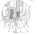
- FIG. 2 A detailed view of the tool 1 of figure 1 in the region where the magnetic force acts between the housing 2 and the backing pad 3 (detail A) is shown in figure 2 .
- a gap 23 is provided between the housing 2 and the backing pad 3 in order allow a working movement of the backing pad 3 in respect to the housing 2.
- the lines of magnetic flux of a magnetic field 24, which is built up between the magnetic elements 16, 17, run across this gap 23, preferably perpendicular in respect to the areal extension of the gap 23 and in respect to the oscillation plane of the backing pad 3.
- the magnetic field 24 is strong enough to generate a magnetic force, which can securely hold the backing pad 3 in a certain rotational position in respect to the housing 2 and which prevents the backing pad 3 from freely rotating about the longitudinal axis 9.
- the backing pad 3 can still perform the first type of working movement, in particular an orbital movement, provoked by the eccentric element 11 rotating about the rotational axis 6.
- a first magnetic element 16 is attached to the housing 2. It may be connected to the housing 2 directly or indirectly by means of one or more additional elements 18 (for example made of metal or plastic material) which are connected to the housing 2.
- additional elements 18 for example made of metal or plastic material
- a hood or cap made of rubber or soft plastic material and bridging the gap 23 along the circumference of the housing 2 could be an example for such an additional element 18.
- the hood or cap 18 comes very close to the top surface of the backing pad 3 and, therefore, is particularly well suited for attachment of the first magnetic elements 16.
- the magnetic elements 16 are each inserted into a receiving cavity 19 through an opening 20 from the side.
- the cavity 19 is located in the additional element 18 but could just as well be located in the housing 2 itself.
- the magnetic element 16 can be fixed within the cavity 19, for example by an adhesive.
- An opening 21 below the magnetic element 16 is directed towards the backing pad 3 and serves for allowing the magnetic force to better interact with the corresponding second magnetic element 17 of the backing pad 3 and for having access to the first magnetic element 16, for example for removing it from the cavity 19, if necessary.
- the second magnetic element 17 can be fixed to any part of the backing pad 3. In this embodiment, it is fixed indirectly to the planar base plate 12 by means of one or more additional elements 12a made of a rigid material. However, it would also be possible to fix the magnetic element 17 directly to or within the rigid base plate 12.
- the second magnetic element 17 is inserted into a cavity from the top through an opening 22. The cavity is located in the additional element 12a or the base plate 12. After insertion of the magnetic element 17 the opening 22 may be closed. This can be achieved by means of a suitable plug element or by injecting a plastic material into the cavity through the opening 22.
- Closing of the opening 22 has the advantage that the magnetic element 17 is fixedly secured within the backing pad 3 and that humidity, dust and dirt are prevented from entering into the cavity and contacting the second magnetic element 17. It is preferred that the magnetic elements 17 are inserted into the backing pad 3 during its production, for example by means of injection molding, so no additional manufacturing step is necessary for fixing the magnetic elements 17 to the backing pad 3 and for closing the openings 22.
- the second magnetic element 17 may be a permanent magnet or a ferromagnetic element.
- the ferromagnetic element may be a small and light weight plate made of low carbon steel or a similar material with good ferromagnetic properties. It would be even possible that the rigid base plate 12 is made of metal which at least partly acts as a ferromagnetic element forming the second magnetic element 17. If the second magnetic elements 17 are embodied as permanent magnets they should have an opposite polarity to the first magnetic elements 16.
- the machine tool 1 is adapted for realizing the first type of working movement if the backing pad 3 with the plurality of second magnetic elements 17 facing the housing 2 is attached to the eccentric element 11 and for realizing a second type of working movement if another backing pad without second magnetic elements is attached to the eccentric element 11.
- the appropriate measures to be taken by the user for switching between the different types of working movements simply consist in mounting different types of backing pads 3 to the eccentric element 11, a first type of backing pad 3 provided with the second magnetic elements 17 (see figure 4 ) and a second type of backing pad without such second magnetic elements (not shown).
- the first magnetic elements 16 provided in the housing 2 are embodied as permanent magnets. Permanent magnets create a static magnetic field and are made of, for example, magnetized low carbon steel, cobalt, nickel, a ferrite or a rare earth element.
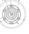
- Figure 3 shows a sectional view of the machine tool 1 of figure 1 in the plane B-B. It can be seen that the backing pad 3 has a circular shape. The section runs through the additional element 18 (e.g. the hood or cap) associated to the housing 2. It can be seen that there are a total of six first magnetic elements 16 associated to the housing 2. The magnetic elements 16 are located around the axis of rotation 6 each having the same given distance to the axis 6 and being circumferentially evenly spaced apart from one another. Of course, the circumferential distance between neighbouring permanent elements 16 could also vary.
- additional element 18 e.g. the hood or cap
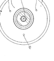
- Figure 4 shows a sectional view of the machine tool 1 of figure 1 in the plane C-C. Part of the top surface of the backing pad 3 can be seen. The section runs through a central part of the planar base plate 12 of the backing pad 3. It can be seen that there are a total of three second magnetic elements 17 associated to the backing pad 3. The magnetic elements 17 are located around the longitudinal axis 9 each having the same given distance to the longitudinal axis 9 and being circumferentially evenly spaced apart from one another.
- the first magnetic elements 16 are embodied as solenoids (electromagnets), which can be electrically activated and deactivated thereby provoking them to create a magnetic field 24 or not.
- the machine tool 1 is adapted for realizing the first type of working movement if the solenoids 16 are activated and generate a magnetic force acting on at least some of the second magnetic elements 17 of the backing pad 3 attached to the eccentric element 11 and for realizing a second type of working movement if the solenoids 16 are deactivated and generate no or only a very small magnetic force, without impact on the second magnetic elements 17 of the backing pad 3.
- the appropriate measures to be taken by the user for switching between the different types of working movements simply consist in electrically activating or deactivating the solenoids 16 constituting the first magnetic elements of the housing 2.
- This can be effected by any type of switching means 10b, for example a mechanical or an electric switch, a rotary switch, a push button, a virtual switch on a touch sensitive display or the like.
- the switching means 10b can be located at any position of the housing 2 accessible from outside the housing 2. In the embodiment of figure 5 the switching means 10b are located at the top side of the housing 2. No switching of a mechanical gear transmission or the like is required for changing the type of working movement.
- Figure 6 shows a sectional view through the machine tool 1 of figure 5 along the line C-C.
- the second magnetic elements 17 embodied as solenoids and located in the hood or cap 18 can be clearly seen.
- the solenoids 17 could also be provided inside the housing 2, in particular along the bottom surface of the housing 2.
- electricity is available for energising the solenoids 16.
- electricity for energising the solenoids 16 could be provided by a rechargeable battery located inside the tool's housing 2.
- a dynamo or generator could be provided in the tool's housing 2, which is actuated by the rotating parts of the machine tool 1, for example the motor shaft 5, and which generates electricity for energising the solenoids 16.
- the electricity generated by the dynamo or generator may be directly provided to the solenoids 16 or buffered in a rechargeable battery or capacitor.
- the number, the magnetic characteristics, the dimensions and/or the positions of the first and/or second magnetic elements 16, 17 can be freely varied in order to achieve a desired strength of the magnetic force acting between the first and second magnetic elements 16, 17.
- the magnetic susceptibility and the magnetic permeability are other characteristics of the magnetic elements 16, 17, which can also influence the intensity and strength of the magnetic force.
- the individual properties of the magnetic elements 16, 17 can be adapted depending on the design of the respective machine tool 1 and the individual operating conditions.
- each of the second magnetic elements 17 of the backing pad 3 performs an orbital movement in respect to the corresponding first magnetic element 16 of the housing 2.
- figure 7 shows a first magnetic element 16 and the corresponding second magnetic element 17 performing an orbital movement 25 about the centre 26 of the first magnetic element 16 during the orbital working movement of the backing pad 3.
- the orbital movement 25 of the second magnetic element 17 its centre 27 rotates on a circle corresponding to the orbital movement 25.
- the diameter of the orbital movement 25 corresponds to twice the distance (indicated with R 25 ) between the rotational axis 6 of the motor shaft 5 and the longitudinal axis 9 of the backing pad 3.
- the first and second magnetic elements 16, 17 have a circular active surface.
- the first magnetic element 16 has a radius of R 16 and the second magnetic element 17 has a radius of R 17 .
- the diameter of the surface of each of the first magnetic elements 16 is at least the size of a diameter (2 x R 17 ) of the surface of the corresponding second magnetic element 17 plus the orbit diameter 2 x R 25 . This assures that during the orbital movement 25 of the backing pad 3 the surfaces of the second magnetic elements 17 are each in continuous coverage with the surfaces of the corresponding first magnetic elements 16. Likewise, this could be achieved if the diameter of the surface of each of the second magnetic elements 17 is at least the size of a diameter (2 x R 16 ) of the surface of the corresponding first magnetic element 16 plus the orbit diameter 2 x R 25 .
Priority Applications (6)
| Application Number | Priority Date | Filing Date | Title |
|---|---|---|---|
| EP18163121.9A EP3501732B1 (fr) | 2018-03-21 | 2018-03-21 | Machine-outil portative de ponçage ou de polissage d'une pièce à usiner conçue pour réaliser deux différents types de mouvements de travail |
| CN201910177309.0A CN109909844B (zh) | 2018-03-21 | 2019-03-08 | 砂磨或抛光工件并实现两种作业运动的手持式机械工具 |
| CN202010857392.9A CN111958431B (zh) | 2018-03-21 | 2019-03-08 | 砂磨或抛光工件并实现两种作业运动的手持式机械工具 |
| JP2019052049A JP6689427B2 (ja) | 2018-03-21 | 2019-03-20 | ワークピースにサンディングまたはポリッシングを行うための二つの異なるタイプの作業動作を実現するよう構成される手持ち型機械工具 |
| US16/360,569 US10661407B2 (en) | 2018-03-21 | 2019-03-21 | Hand-held and hand-guided power tool having a working element releasably attached thereto, and for such a power tool |
| JP2020069019A JP6986110B2 (ja) | 2018-03-21 | 2020-04-07 | ワークピースにサンディングまたはポリッシングを行うための二つの異なるタイプの作業動作を実現するよう構成される手持ち型機械工具 |
Applications Claiming Priority (1)
| Application Number | Priority Date | Filing Date | Title |
|---|---|---|---|
| EP18163121.9A EP3501732B1 (fr) | 2018-03-21 | 2018-03-21 | Machine-outil portative de ponçage ou de polissage d'une pièce à usiner conçue pour réaliser deux différents types de mouvements de travail |
Publications (2)
| Publication Number | Publication Date |
|---|---|
| EP3501732A1 true EP3501732A1 (fr) | 2019-06-26 |
| EP3501732B1 EP3501732B1 (fr) | 2020-05-13 |
Family
ID=61731708
Family Applications (1)
| Application Number | Title | Priority Date | Filing Date |
|---|---|---|---|
| EP18163121.9A Active EP3501732B1 (fr) | 2018-03-21 | 2018-03-21 | Machine-outil portative de ponçage ou de polissage d'une pièce à usiner conçue pour réaliser deux différents types de mouvements de travail |
Country Status (4)
| Country | Link |
|---|---|
| US (1) | US10661407B2 (fr) |
| EP (1) | EP3501732B1 (fr) |
| JP (2) | JP6689427B2 (fr) |
| CN (2) | CN109909844B (fr) |
Cited By (7)
| Publication number | Priority date | Publication date | Assignee | Title |
|---|---|---|---|---|
| TWI690385B (zh) * | 2019-06-28 | 2020-04-11 | 鼎朋企業股份有限公司 | 具隨意偏心軌道運動速度檢測的研磨工具機 |
| CN111545589A (zh) * | 2020-05-19 | 2020-08-18 | 马永会 | 一种基于磁力自动清理打磨碎屑的磁性钢带的加工方法 |
| EP3854523A1 (fr) | 2020-01-23 | 2021-07-28 | Guido Valentini | Unité fonctionnelle pour un outil électrique guidé à la main et outil électrique équipé d'une telle unité fonctionnelle |
| EP3854526A1 (fr) | 2020-01-23 | 2021-07-28 | Guido Valentini | Enveloppe de protection pour un outil électrique guidé à la main et outil électrique guidé à la main équipé d'une telle enveloppe de protection |
| CN114670100A (zh) * | 2022-03-18 | 2022-06-28 | 浙江承康机电制造有限公司 | 一种双握手柄式抛光机 |
| CN114851056A (zh) * | 2022-05-27 | 2022-08-05 | 湖南宇环精密制造有限公司 | 一种偏心抛光机构 |
| CN115106898A (zh) * | 2021-03-23 | 2022-09-27 | 安德里亚·瓦伦蒂尼 | 适用于与手持抛光或砂光动力工具可拆卸附接的板状垫板 |
Families Citing this family (5)
| Publication number | Priority date | Publication date | Assignee | Title |
|---|---|---|---|---|
| EP3501732B1 (fr) * | 2018-03-21 | 2020-05-13 | Guido Valentini | Machine-outil portative de ponçage ou de polissage d'une pièce à usiner conçue pour réaliser deux différents types de mouvements de travail |
| USD925318S1 (en) * | 2019-02-28 | 2021-07-20 | Guido Valentini | Delta shaped backing pad with dove-tail |
| KR102570519B1 (ko) * | 2021-05-11 | 2023-08-25 | 주식회사 디어포스 | 멀티홀사용가능 고 호환성 연마패드조립체 |
| CN113523984B (zh) * | 2021-07-16 | 2022-08-16 | 无锡中车时代智能装备研究院有限公司 | 一种多头智能打磨装置 |
| KR102560353B1 (ko) * | 2022-10-31 | 2023-07-26 | 최홍진 | 탈부착이 가능한 지그용 연마장치 |
Citations (1)
| Publication number | Priority date | Publication date | Assignee | Title |
|---|---|---|---|---|
| EP0623422A1 (fr) * | 1993-05-05 | 1994-11-09 | C. & E. FEIN GmbH & Co. | Outil électrique |
Family Cites Families (21)
| Publication number | Priority date | Publication date | Assignee | Title |
|---|---|---|---|---|
| US5018314A (en) * | 1989-06-08 | 1991-05-28 | Makita Electric Works, Ltd. | Sander |
| DE4233729A1 (de) * | 1992-10-07 | 1994-04-14 | Bosch Gmbh Robert | Exzentertellerschleifer mit Schleiftellerbremse |
| US5384984A (en) * | 1993-01-22 | 1995-01-31 | Porter-Cable Corporation | Random orbit sander with brake |
| DE19952108B4 (de) * | 1999-10-29 | 2007-09-20 | Robert Bosch Gmbh | Exzentertellerschleifmaschine |
| DE10135251A1 (de) * | 2001-07-19 | 2003-02-06 | Bosch Gmbh Robert | Handwerkzeugmaschine |
| JP4061053B2 (ja) * | 2001-11-16 | 2008-03-12 | 日本電産シバウラ株式会社 | 電動サンダ |
| JP2004348484A (ja) * | 2003-05-22 | 2004-12-09 | Nippon Telegr & Teleph Corp <Ntt> | 部分文書取得方法、システム、プログラム、および記録媒体 |
| DE102004001546A1 (de) * | 2004-01-10 | 2005-08-04 | August Rüggeberg Gmbh & Co. Kg | Werkzeug |
| ITVI20040090A1 (it) * | 2004-04-16 | 2004-07-16 | Positec Group Ltd | Dispositivo antivibrante per macchina levigatrice motorizzata, e macchina levigatrice incorporante tale dispositivo |
| EP1714739A1 (fr) * | 2005-04-19 | 2006-10-25 | Positec Power Tools (Suzhou) Co., Ltd. | Ponceuse portative |
| CN1724216A (zh) * | 2005-07-21 | 2006-01-25 | 苏州宝时得电动工具有限公司 | 多功能砂光机 |
| CN101172331A (zh) * | 2006-11-02 | 2008-05-07 | 苏州宝时得电动工具有限公司 | 多功能砂光机 |
| JP5663858B2 (ja) * | 2009-11-06 | 2015-02-04 | 日立工機株式会社 | 携帯研磨機 |
| JP2012176475A (ja) * | 2011-02-28 | 2012-09-13 | Ryobi Ltd | サンダ |
| KR20140022913A (ko) * | 2011-05-15 | 2014-02-25 | 카펠, 안드레아스 | 로터리 드라이브 |
| EP2735402B1 (fr) * | 2012-11-23 | 2016-05-04 | Guido Valentini | Machine-outil portative de ponçage ou de polissage d'une pièce à usiner |
| EP3028811B1 (fr) * | 2014-12-05 | 2017-03-01 | Guido Valentini | Tampon de support pour un outil de polissage ou de sablage guidé à la main et ledit outil de polissage ou de sablage guidé avec un tel tampon |
| EP3238878A1 (fr) * | 2016-04-27 | 2017-11-01 | Guido Valentini | Machine outil de meulage ou de polissage guidée à la main ou portative |
| CN107745312B (zh) * | 2016-06-28 | 2020-08-14 | 苏州宝时得电动工具有限公司 | 砂光机及其操作方法和工作底板的拆装方法 |
| WO2018001284A1 (fr) * | 2016-06-28 | 2018-01-04 | 苏州宝时得电动工具有限公司 | Ponceuse, son procédé de fonctionnement et procédé de montage et de démontage de plaque de base de travail |
| EP3501732B1 (fr) * | 2018-03-21 | 2020-05-13 | Guido Valentini | Machine-outil portative de ponçage ou de polissage d'une pièce à usiner conçue pour réaliser deux différents types de mouvements de travail |
-
2018
- 2018-03-21 EP EP18163121.9A patent/EP3501732B1/fr active Active
-
2019
- 2019-03-08 CN CN201910177309.0A patent/CN109909844B/zh active Active
- 2019-03-08 CN CN202010857392.9A patent/CN111958431B/zh active Active
- 2019-03-20 JP JP2019052049A patent/JP6689427B2/ja active Active
- 2019-03-21 US US16/360,569 patent/US10661407B2/en active Active
-
2020
- 2020-04-07 JP JP2020069019A patent/JP6986110B2/ja active Active
Patent Citations (1)
| Publication number | Priority date | Publication date | Assignee | Title |
|---|---|---|---|---|
| EP0623422A1 (fr) * | 1993-05-05 | 1994-11-09 | C. & E. FEIN GmbH & Co. | Outil électrique |
Cited By (8)
| Publication number | Priority date | Publication date | Assignee | Title |
|---|---|---|---|---|
| TWI690385B (zh) * | 2019-06-28 | 2020-04-11 | 鼎朋企業股份有限公司 | 具隨意偏心軌道運動速度檢測的研磨工具機 |
| EP3854523A1 (fr) | 2020-01-23 | 2021-07-28 | Guido Valentini | Unité fonctionnelle pour un outil électrique guidé à la main et outil électrique équipé d'une telle unité fonctionnelle |
| EP3854526A1 (fr) | 2020-01-23 | 2021-07-28 | Guido Valentini | Enveloppe de protection pour un outil électrique guidé à la main et outil électrique guidé à la main équipé d'une telle enveloppe de protection |
| CN111545589A (zh) * | 2020-05-19 | 2020-08-18 | 马永会 | 一种基于磁力自动清理打磨碎屑的磁性钢带的加工方法 |
| CN115106898A (zh) * | 2021-03-23 | 2022-09-27 | 安德里亚·瓦伦蒂尼 | 适用于与手持抛光或砂光动力工具可拆卸附接的板状垫板 |
| CN115106898B (zh) * | 2021-03-23 | 2024-01-30 | 安德里亚·瓦伦蒂尼 | 适用于与手持抛光或砂光动力工具可拆卸附接的板状垫板 |
| CN114670100A (zh) * | 2022-03-18 | 2022-06-28 | 浙江承康机电制造有限公司 | 一种双握手柄式抛光机 |
| CN114851056A (zh) * | 2022-05-27 | 2022-08-05 | 湖南宇环精密制造有限公司 | 一种偏心抛光机构 |
Also Published As
| Publication number | Publication date |
|---|---|
| CN109909844A (zh) | 2019-06-21 |
| US20190291233A1 (en) | 2019-09-26 |
| CN111958431A (zh) | 2020-11-20 |
| EP3501732B1 (fr) | 2020-05-13 |
| JP2020146834A (ja) | 2020-09-17 |
| CN109909844B (zh) | 2021-01-26 |
| CN111958431B (zh) | 2022-11-18 |
| JP6986110B2 (ja) | 2021-12-22 |
| JP6689427B2 (ja) | 2020-04-28 |
| US10661407B2 (en) | 2020-05-26 |
| JP2019171562A (ja) | 2019-10-10 |
Similar Documents
| Publication | Publication Date | Title |
|---|---|---|
| EP3501732B1 (fr) | Machine-outil portative de ponçage ou de polissage d'une pièce à usiner conçue pour réaliser deux différents types de mouvements de travail | |
| US5595531A (en) | Random orbit sander having speed limiter | |
| CN100566092C (zh) | 能往复线性驱动和滚动驱动的致动器及使用它的电动牙刷 | |
| EP3501753B1 (fr) | Outil à moteur électrique ou pneumatique guidé et/ou tenu à la main | |
| JP2020146832A (ja) | 手持ち型・手動誘導型ランダム軌道ポリッシングまたはサンダー仕上げ動力駆動工具 | |
| EP3656503B1 (fr) | Outil électrique de ponçage ou de polissage orbital aléatoire guidé à la main portatif | |
| JP6697834B2 (ja) | 電動グラインダー | |
| US3226888A (en) | Magnetic abrasive disc holder and disc | |
| EP2735402B1 (fr) | Machine-outil portative de ponçage ou de polissage d'une pièce à usiner | |
| CN104379303A (zh) | 工具机制动装置 | |
| CN111906657B (zh) | 用于对工件进行砂磨或抛光的手持式动力工具 | |
| CN103934809B (zh) | 工具机制动装置 | |
| CA2915284C (fr) | Ensemble de travail destine a etre utilise dans une machine agricole et machine agricole | |
| EP4063069A1 (fr) | Tampon de support en forme de plaque adapté pour une fixation amovible à un outil de polissage ou de sablage à main | |
| CN210160910U (zh) | 一种金相检测用磨抛机 | |
| CN113904493B (zh) | 电磁动力飞轮装置及具有其的设备 | |
| US20220241916A1 (en) | Magnet holder and a magnetic drill comprising it | |
| JP2017087312A (ja) | ハンディグラインダ | |
| KR200270718Y1 (ko) | 자기연마기 | |
| KR101549115B1 (ko) | 전동공구의 스핀들락 장치 | |
| JPS6292742A (ja) | 伝動装置 |
Legal Events
| Date | Code | Title | Description |
|---|---|---|---|
| PUAI | Public reference made under article 153(3) epc to a published international application that has entered the european phase |
Free format text: ORIGINAL CODE: 0009012 |
|
| STAA | Information on the status of an ep patent application or granted ep patent |
Free format text: STATUS: REQUEST FOR EXAMINATION WAS MADE |
|
| 17P | Request for examination filed |
Effective date: 20190211 |
|
| AK | Designated contracting states |
Kind code of ref document: A1 Designated state(s): AL AT BE BG CH CY CZ DE DK EE ES FI FR GB GR HR HU IE IS IT LI LT LU LV MC MK MT NL NO PL PT RO RS SE SI SK SM TR |
|
| AX | Request for extension of the european patent |
Extension state: BA ME |
|
| GRAP | Despatch of communication of intention to grant a patent |
Free format text: ORIGINAL CODE: EPIDOSNIGR1 |
|
| STAA | Information on the status of an ep patent application or granted ep patent |
Free format text: STATUS: GRANT OF PATENT IS INTENDED |
|
| INTG | Intention to grant announced |
Effective date: 20191030 |
|
| GRAS | Grant fee paid |
Free format text: ORIGINAL CODE: EPIDOSNIGR3 |
|
| GRAA | (expected) grant |
Free format text: ORIGINAL CODE: 0009210 |
|
| STAA | Information on the status of an ep patent application or granted ep patent |
Free format text: STATUS: THE PATENT HAS BEEN GRANTED |
|
| AK | Designated contracting states |
Kind code of ref document: B1 Designated state(s): AL AT BE BG CH CY CZ DE DK EE ES FI FR GB GR HR HU IE IS IT LI LT LU LV MC MK MT NL NO PL PT RO RS SE SI SK SM TR |
|
| REG | Reference to a national code |
Ref country code: GB Ref legal event code: FG4D |
|
| REG | Reference to a national code |
Ref country code: CH Ref legal event code: EP |
|
| REG | Reference to a national code |
Ref country code: DE Ref legal event code: R096 Ref document number: 602018004346 Country of ref document: DE |
|
| REG | Reference to a national code |
Ref country code: AT Ref legal event code: REF Ref document number: 1269634 Country of ref document: AT Kind code of ref document: T Effective date: 20200615 |
|
| REG | Reference to a national code |
Ref country code: LT Ref legal event code: MG4D |
|
| REG | Reference to a national code |
Ref country code: NL Ref legal event code: MP Effective date: 20200513 |
|
| PG25 | Lapsed in a contracting state [announced via postgrant information from national office to epo] |
Ref country code: LT Free format text: LAPSE BECAUSE OF FAILURE TO SUBMIT A TRANSLATION OF THE DESCRIPTION OR TO PAY THE FEE WITHIN THE PRESCRIBED TIME-LIMIT Effective date: 20200513 Ref country code: FI Free format text: LAPSE BECAUSE OF FAILURE TO SUBMIT A TRANSLATION OF THE DESCRIPTION OR TO PAY THE FEE WITHIN THE PRESCRIBED TIME-LIMIT Effective date: 20200513 Ref country code: GR Free format text: LAPSE BECAUSE OF FAILURE TO SUBMIT A TRANSLATION OF THE DESCRIPTION OR TO PAY THE FEE WITHIN THE PRESCRIBED TIME-LIMIT Effective date: 20200814 Ref country code: PT Free format text: LAPSE BECAUSE OF FAILURE TO SUBMIT A TRANSLATION OF THE DESCRIPTION OR TO PAY THE FEE WITHIN THE PRESCRIBED TIME-LIMIT Effective date: 20200914 Ref country code: SE Free format text: LAPSE BECAUSE OF FAILURE TO SUBMIT A TRANSLATION OF THE DESCRIPTION OR TO PAY THE FEE WITHIN THE PRESCRIBED TIME-LIMIT Effective date: 20200513 Ref country code: IS Free format text: LAPSE BECAUSE OF FAILURE TO SUBMIT A TRANSLATION OF THE DESCRIPTION OR TO PAY THE FEE WITHIN THE PRESCRIBED TIME-LIMIT Effective date: 20200913 Ref country code: NO Free format text: LAPSE BECAUSE OF FAILURE TO SUBMIT A TRANSLATION OF THE DESCRIPTION OR TO PAY THE FEE WITHIN THE PRESCRIBED TIME-LIMIT Effective date: 20200813 |
|
| PG25 | Lapsed in a contracting state [announced via postgrant information from national office to epo] |
Ref country code: HR Free format text: LAPSE BECAUSE OF FAILURE TO SUBMIT A TRANSLATION OF THE DESCRIPTION OR TO PAY THE FEE WITHIN THE PRESCRIBED TIME-LIMIT Effective date: 20200513 Ref country code: RS Free format text: LAPSE BECAUSE OF FAILURE TO SUBMIT A TRANSLATION OF THE DESCRIPTION OR TO PAY THE FEE WITHIN THE PRESCRIBED TIME-LIMIT Effective date: 20200513 Ref country code: BG Free format text: LAPSE BECAUSE OF FAILURE TO SUBMIT A TRANSLATION OF THE DESCRIPTION OR TO PAY THE FEE WITHIN THE PRESCRIBED TIME-LIMIT Effective date: 20200813 Ref country code: LV Free format text: LAPSE BECAUSE OF FAILURE TO SUBMIT A TRANSLATION OF THE DESCRIPTION OR TO PAY THE FEE WITHIN THE PRESCRIBED TIME-LIMIT Effective date: 20200513 |
|
| REG | Reference to a national code |
Ref country code: AT Ref legal event code: MK05 Ref document number: 1269634 Country of ref document: AT Kind code of ref document: T Effective date: 20200513 |
|
| PG25 | Lapsed in a contracting state [announced via postgrant information from national office to epo] |
Ref country code: NL Free format text: LAPSE BECAUSE OF FAILURE TO SUBMIT A TRANSLATION OF THE DESCRIPTION OR TO PAY THE FEE WITHIN THE PRESCRIBED TIME-LIMIT Effective date: 20200513 Ref country code: AL Free format text: LAPSE BECAUSE OF FAILURE TO SUBMIT A TRANSLATION OF THE DESCRIPTION OR TO PAY THE FEE WITHIN THE PRESCRIBED TIME-LIMIT Effective date: 20200513 |
|
| PG25 | Lapsed in a contracting state [announced via postgrant information from national office to epo] |
Ref country code: SM Free format text: LAPSE BECAUSE OF FAILURE TO SUBMIT A TRANSLATION OF THE DESCRIPTION OR TO PAY THE FEE WITHIN THE PRESCRIBED TIME-LIMIT Effective date: 20200513 Ref country code: EE Free format text: LAPSE BECAUSE OF FAILURE TO SUBMIT A TRANSLATION OF THE DESCRIPTION OR TO PAY THE FEE WITHIN THE PRESCRIBED TIME-LIMIT Effective date: 20200513 Ref country code: RO Free format text: LAPSE BECAUSE OF FAILURE TO SUBMIT A TRANSLATION OF THE DESCRIPTION OR TO PAY THE FEE WITHIN THE PRESCRIBED TIME-LIMIT Effective date: 20200513 Ref country code: CZ Free format text: LAPSE BECAUSE OF FAILURE TO SUBMIT A TRANSLATION OF THE DESCRIPTION OR TO PAY THE FEE WITHIN THE PRESCRIBED TIME-LIMIT Effective date: 20200513 Ref country code: ES Free format text: LAPSE BECAUSE OF FAILURE TO SUBMIT A TRANSLATION OF THE DESCRIPTION OR TO PAY THE FEE WITHIN THE PRESCRIBED TIME-LIMIT Effective date: 20200513 Ref country code: AT Free format text: LAPSE BECAUSE OF FAILURE TO SUBMIT A TRANSLATION OF THE DESCRIPTION OR TO PAY THE FEE WITHIN THE PRESCRIBED TIME-LIMIT Effective date: 20200513 Ref country code: DK Free format text: LAPSE BECAUSE OF FAILURE TO SUBMIT A TRANSLATION OF THE DESCRIPTION OR TO PAY THE FEE WITHIN THE PRESCRIBED TIME-LIMIT Effective date: 20200513 |
|
| REG | Reference to a national code |
Ref country code: DE Ref legal event code: R097 Ref document number: 602018004346 Country of ref document: DE |
|
| PG25 | Lapsed in a contracting state [announced via postgrant information from national office to epo] |
Ref country code: PL Free format text: LAPSE BECAUSE OF FAILURE TO SUBMIT A TRANSLATION OF THE DESCRIPTION OR TO PAY THE FEE WITHIN THE PRESCRIBED TIME-LIMIT Effective date: 20200513 Ref country code: SK Free format text: LAPSE BECAUSE OF FAILURE TO SUBMIT A TRANSLATION OF THE DESCRIPTION OR TO PAY THE FEE WITHIN THE PRESCRIBED TIME-LIMIT Effective date: 20200513 |
|
| PLBE | No opposition filed within time limit |
Free format text: ORIGINAL CODE: 0009261 |
|
| STAA | Information on the status of an ep patent application or granted ep patent |
Free format text: STATUS: NO OPPOSITION FILED WITHIN TIME LIMIT |
|
| 26N | No opposition filed |
Effective date: 20210216 |
|
| PG25 | Lapsed in a contracting state [announced via postgrant information from national office to epo] |
Ref country code: SI Free format text: LAPSE BECAUSE OF FAILURE TO SUBMIT A TRANSLATION OF THE DESCRIPTION OR TO PAY THE FEE WITHIN THE PRESCRIBED TIME-LIMIT Effective date: 20200513 |
|
| PG25 | Lapsed in a contracting state [announced via postgrant information from national office to epo] |
Ref country code: MC Free format text: LAPSE BECAUSE OF FAILURE TO SUBMIT A TRANSLATION OF THE DESCRIPTION OR TO PAY THE FEE WITHIN THE PRESCRIBED TIME-LIMIT Effective date: 20200513 |
|
| REG | Reference to a national code |
Ref country code: CH Ref legal event code: PL |
|
| REG | Reference to a national code |
Ref country code: BE Ref legal event code: MM Effective date: 20210331 |
|
| PG25 | Lapsed in a contracting state [announced via postgrant information from national office to epo] |
Ref country code: IE Free format text: LAPSE BECAUSE OF NON-PAYMENT OF DUE FEES Effective date: 20210321 Ref country code: LI Free format text: LAPSE BECAUSE OF NON-PAYMENT OF DUE FEES Effective date: 20210331 Ref country code: LU Free format text: LAPSE BECAUSE OF NON-PAYMENT OF DUE FEES Effective date: 20210321 Ref country code: CH Free format text: LAPSE BECAUSE OF NON-PAYMENT OF DUE FEES Effective date: 20210331 |
|
| PG25 | Lapsed in a contracting state [announced via postgrant information from national office to epo] |
Ref country code: BE Free format text: LAPSE BECAUSE OF NON-PAYMENT OF DUE FEES Effective date: 20210331 |
|
| REG | Reference to a national code |
Ref country code: DE Ref legal event code: R082 Ref document number: 602018004346 Country of ref document: DE Representative=s name: WOERZ PATENTANWAELTE PARTNERSCHAFTSGESELLSCHAF, DE |
|
| PGFP | Annual fee paid to national office [announced via postgrant information from national office to epo] |
Ref country code: FR Payment date: 20230320 Year of fee payment: 6 |
|
| P01 | Opt-out of the competence of the unified patent court (upc) registered |
Effective date: 20230513 |
|
| PG25 | Lapsed in a contracting state [announced via postgrant information from national office to epo] |
Ref country code: CY Free format text: LAPSE BECAUSE OF FAILURE TO SUBMIT A TRANSLATION OF THE DESCRIPTION OR TO PAY THE FEE WITHIN THE PRESCRIBED TIME-LIMIT Effective date: 20200513 |
|
| PG25 | Lapsed in a contracting state [announced via postgrant information from national office to epo] |
Ref country code: HU Free format text: LAPSE BECAUSE OF FAILURE TO SUBMIT A TRANSLATION OF THE DESCRIPTION OR TO PAY THE FEE WITHIN THE PRESCRIBED TIME-LIMIT; INVALID AB INITIO Effective date: 20180321 |
|
| PGFP | Annual fee paid to national office [announced via postgrant information from national office to epo] |
Ref country code: IT Payment date: 20230331 Year of fee payment: 6 Ref country code: DE Payment date: 20230413 Year of fee payment: 6 |
|
| PG25 | Lapsed in a contracting state [announced via postgrant information from national office to epo] |
Ref country code: MK Free format text: LAPSE BECAUSE OF FAILURE TO SUBMIT A TRANSLATION OF THE DESCRIPTION OR TO PAY THE FEE WITHIN THE PRESCRIBED TIME-LIMIT Effective date: 20200513 |
|
| PGFP | Annual fee paid to national office [announced via postgrant information from national office to epo] |
Ref country code: GB Payment date: 20240327 Year of fee payment: 7 |