EP3500445B1 - Höhenstandmessvorrichtung für ein fahrzeug - Google Patents
Höhenstandmessvorrichtung für ein fahrzeug Download PDFInfo
- Publication number
- EP3500445B1 EP3500445B1 EP17762050.7A EP17762050A EP3500445B1 EP 3500445 B1 EP3500445 B1 EP 3500445B1 EP 17762050 A EP17762050 A EP 17762050A EP 3500445 B1 EP3500445 B1 EP 3500445B1
- Authority
- EP
- European Patent Office
- Prior art keywords
- vehicle
- sensor
- acceleration
- height
- signal
- Prior art date
- Legal status (The legal status is an assumption and is not a legal conclusion. Google has not performed a legal analysis and makes no representation as to the accuracy of the status listed.)
- Active
Links
Images

Classifications
-
- B—PERFORMING OPERATIONS; TRANSPORTING
- B60—VEHICLES IN GENERAL
- B60G—VEHICLE SUSPENSION ARRANGEMENTS
- B60G17/00—Resilient suspensions having means for adjusting the spring or vibration-damper characteristics, for regulating the distance between a supporting surface and a sprung part of vehicle or for locking suspension during use to meet varying vehicular or surface conditions, e.g. due to speed or load
- B60G17/015—Resilient suspensions having means for adjusting the spring or vibration-damper characteristics, for regulating the distance between a supporting surface and a sprung part of vehicle or for locking suspension during use to meet varying vehicular or surface conditions, e.g. due to speed or load the regulating means comprising electric or electronic elements
- B60G17/019—Resilient suspensions having means for adjusting the spring or vibration-damper characteristics, for regulating the distance between a supporting surface and a sprung part of vehicle or for locking suspension during use to meet varying vehicular or surface conditions, e.g. due to speed or load the regulating means comprising electric or electronic elements characterised by the type of sensor or the arrangement thereof
- B60G17/01908—Acceleration or inclination sensors
-
- B—PERFORMING OPERATIONS; TRANSPORTING
- B60—VEHICLES IN GENERAL
- B60Q—ARRANGEMENT OF SIGNALLING OR LIGHTING DEVICES, THE MOUNTING OR SUPPORTING THEREOF OR CIRCUITS THEREFOR, FOR VEHICLES IN GENERAL
- B60Q1/00—Arrangement of optical signalling or lighting devices, the mounting or supporting thereof or circuits therefor
- B60Q1/02—Arrangement of optical signalling or lighting devices, the mounting or supporting thereof or circuits therefor the devices being primarily intended to illuminate the way ahead or to illuminate other areas of way or environments
- B60Q1/04—Arrangement of optical signalling or lighting devices, the mounting or supporting thereof or circuits therefor the devices being primarily intended to illuminate the way ahead or to illuminate other areas of way or environments the devices being headlights
- B60Q1/06—Arrangement of optical signalling or lighting devices, the mounting or supporting thereof or circuits therefor the devices being primarily intended to illuminate the way ahead or to illuminate other areas of way or environments the devices being headlights adjustable, e.g. remotely-controlled from inside vehicle
- B60Q1/08—Arrangement of optical signalling or lighting devices, the mounting or supporting thereof or circuits therefor the devices being primarily intended to illuminate the way ahead or to illuminate other areas of way or environments the devices being headlights adjustable, e.g. remotely-controlled from inside vehicle automatically
- B60Q1/10—Arrangement of optical signalling or lighting devices, the mounting or supporting thereof or circuits therefor the devices being primarily intended to illuminate the way ahead or to illuminate other areas of way or environments the devices being headlights adjustable, e.g. remotely-controlled from inside vehicle automatically due to vehicle inclination, e.g. due to load distribution
-
- G—PHYSICS
- G01—MEASURING; TESTING
- G01P—MEASURING LINEAR OR ANGULAR SPEED, ACCELERATION, DECELERATION, OR SHOCK; INDICATING PRESENCE, ABSENCE, OR DIRECTION, OF MOVEMENT
- G01P15/00—Measuring acceleration; Measuring deceleration; Measuring shock, i.e. sudden change of acceleration
- G01P15/02—Measuring acceleration; Measuring deceleration; Measuring shock, i.e. sudden change of acceleration by making use of inertia forces using solid seismic masses
- G01P15/08—Measuring acceleration; Measuring deceleration; Measuring shock, i.e. sudden change of acceleration by making use of inertia forces using solid seismic masses with conversion into electric or magnetic values
-
- B—PERFORMING OPERATIONS; TRANSPORTING
- B60—VEHICLES IN GENERAL
- B60G—VEHICLE SUSPENSION ARRANGEMENTS
- B60G2200/00—Indexing codes relating to suspension types
- B60G2200/10—Independent suspensions
- B60G2200/14—Independent suspensions with lateral arms
- B60G2200/142—Independent suspensions with lateral arms with a single lateral arm, e.g. MacPherson type
-
- B—PERFORMING OPERATIONS; TRANSPORTING
- B60—VEHICLES IN GENERAL
- B60G—VEHICLE SUSPENSION ARRANGEMENTS
- B60G2204/00—Indexing codes related to suspensions per se or to auxiliary parts
- B60G2204/10—Mounting of suspension elements
- B60G2204/11—Mounting of sensors thereon
- B60G2204/116—Sensors coupled to the suspension arm
- B60G2204/1162—Sensors coupled to the suspension arm directly mounted on the suspension arm
-
- B—PERFORMING OPERATIONS; TRANSPORTING
- B60—VEHICLES IN GENERAL
- B60G—VEHICLE SUSPENSION ARRANGEMENTS
- B60G2400/00—Indexing codes relating to detected, measured or calculated conditions or factors
- B60G2400/05—Attitude
- B60G2400/052—Angular rate
-
- B—PERFORMING OPERATIONS; TRANSPORTING
- B60—VEHICLES IN GENERAL
- B60G—VEHICLE SUSPENSION ARRANGEMENTS
- B60G2400/00—Indexing codes relating to detected, measured or calculated conditions or factors
- B60G2400/10—Acceleration; Deceleration
- B60G2400/102—Acceleration; Deceleration vertical
-
- B—PERFORMING OPERATIONS; TRANSPORTING
- B60—VEHICLES IN GENERAL
- B60G—VEHICLE SUSPENSION ARRANGEMENTS
- B60G2400/00—Indexing codes relating to detected, measured or calculated conditions or factors
- B60G2400/25—Stroke; Height; Displacement
- B60G2400/252—Stroke; Height; Displacement vertical
-
- B—PERFORMING OPERATIONS; TRANSPORTING
- B60—VEHICLES IN GENERAL
- B60G—VEHICLE SUSPENSION ARRANGEMENTS
- B60G2600/00—Indexing codes relating to particular elements, systems or processes used on suspension systems or suspension control systems
- B60G2600/08—Failure or malfunction detecting means
- B60G2600/082—Sensor drift
-
- B—PERFORMING OPERATIONS; TRANSPORTING
- B60—VEHICLES IN GENERAL
- B60G—VEHICLE SUSPENSION ARRANGEMENTS
- B60G2800/00—Indexing codes relating to the type of movement or to the condition of the vehicle and to the end result to be achieved by the control action
- B60G2800/01—Attitude or posture control
- B60G2800/016—Yawing condition
-
- B—PERFORMING OPERATIONS; TRANSPORTING
- B60—VEHICLES IN GENERAL
- B60Q—ARRANGEMENT OF SIGNALLING OR LIGHTING DEVICES, THE MOUNTING OR SUPPORTING THEREOF OR CIRCUITS THEREFOR, FOR VEHICLES IN GENERAL
- B60Q1/00—Arrangement of optical signalling or lighting devices, the mounting or supporting thereof or circuits therefor
- B60Q1/02—Arrangement of optical signalling or lighting devices, the mounting or supporting thereof or circuits therefor the devices being primarily intended to illuminate the way ahead or to illuminate other areas of way or environments
- B60Q1/04—Arrangement of optical signalling or lighting devices, the mounting or supporting thereof or circuits therefor the devices being primarily intended to illuminate the way ahead or to illuminate other areas of way or environments the devices being headlights
- B60Q1/06—Arrangement of optical signalling or lighting devices, the mounting or supporting thereof or circuits therefor the devices being primarily intended to illuminate the way ahead or to illuminate other areas of way or environments the devices being headlights adjustable, e.g. remotely-controlled from inside vehicle
- B60Q1/08—Arrangement of optical signalling or lighting devices, the mounting or supporting thereof or circuits therefor the devices being primarily intended to illuminate the way ahead or to illuminate other areas of way or environments the devices being headlights adjustable, e.g. remotely-controlled from inside vehicle automatically
- B60Q1/12—Arrangement of optical signalling or lighting devices, the mounting or supporting thereof or circuits therefor the devices being primarily intended to illuminate the way ahead or to illuminate other areas of way or environments the devices being headlights adjustable, e.g. remotely-controlled from inside vehicle automatically due to steering position
-
- B—PERFORMING OPERATIONS; TRANSPORTING
- B60—VEHICLES IN GENERAL
- B60Q—ARRANGEMENT OF SIGNALLING OR LIGHTING DEVICES, THE MOUNTING OR SUPPORTING THEREOF OR CIRCUITS THEREFOR, FOR VEHICLES IN GENERAL
- B60Q2300/00—Indexing codes for automatically adjustable headlamps or automatically dimmable headlamps
- B60Q2300/10—Indexing codes relating to particular vehicle conditions
- B60Q2300/13—Attitude of the vehicle body
- B60Q2300/132—Pitch
-
- B—PERFORMING OPERATIONS; TRANSPORTING
- B60—VEHICLES IN GENERAL
- B60Y—INDEXING SCHEME RELATING TO ASPECTS CROSS-CUTTING VEHICLE TECHNOLOGY
- B60Y2400/00—Special features of vehicle units
- B60Y2400/30—Sensors
- B60Y2400/304—Acceleration sensors
Definitions
- the invention relates to a ride height measuring device for a vehicle, with a sensor arrangement, by means of which a position of at least one sensor signals that connect a vehicle wheel to a vehicle body and articulately connected to it can be generated relative to the vehicle body, and an evaluation device connected to the sensor arrangement, by means of which while evaluating the sensor signals, at least one level information characterizing a level of the vehicle body can be formed, the sensor arrangement having one or at least one acceleration sensor, which is stationary relative to the chassis component, for detecting the acceleration acting on the chassis component, by means of which at least one sensor signal characterizing this acceleration can be generated, and at least comprises a reference sensor that is stationary relative to the vehicle body for detecting the acceleration acting on the vehicle body, by means of w by which at least one sensor signal characterizing this acceleration can be generated.
- Such a height measuring device is from DE 103 56 402 A1 known.
- Chassis components in particular ball joints, have, among other things, the task of resiliently mounting the chassis of a vehicle on its vehicle wheels.
- the components of the chassis adapt to the condition of the road surface and the respective driving condition, so that the vehicle occupant is offered a high level of safety and comfort.
- Joints and links which take on the task of the wheel suspension and enable steering, play an important role.
- headlight range control can be implemented with height detection.
- the angular position of a joint can be recorded by an electrical evaluation device and / or a sensor device. By evaluating the The data provided in this way can be used to measure the height, which provides information for headlight range control or for active chassis control, such as Continuous Damping Control (CDC) or roll stabilization.
- CDC Continuous Damping Control
- a magnetic field sensor measures the angle between the ball stud and the housing of a ball joint by the magnetic field sensor, attached to a cover of the housing, evaluating the magnetic field of a magnet located in the ball stud.
- Articulated connections are subject to the interference of electromagnetic fields. These arise in particular from electrical components or machines arranged in the vicinity of the magnetic field sensor, such as electrical lines or consumers, for example electric motors.
- a magnetic field sensor such as a Hall sensor
- it measures both the magnetic field of the magnet located in the ball stud and the external interference field.
- the angle signal is thus falsified.
- lever ratios, mechanical components due to wear and tear and tolerances have a disruptive effect on the angle signal. Over the lifetime of the ride height sensors, these influences increase and the signal accuracy deteriorates further.
- the invention is based on the object of developing a level measuring device of the type mentioned at the beginning in such a way that the aforementioned problems can be avoided.
- the ride height measuring device for a vehicle in particular a motor vehicle, has a sensor arrangement, by means of which the or one position of one or at least one of the vehicle wheels connects and articulates with a vehicle body the chassis component connected to the vehicle body relative to the vehicle body characterizing sensor signals can be generated, and an evaluation device connected to the sensor arrangement, by means of which, by evaluating the sensor signals, one or at least one level information characterizing the level of the vehicle body can be formed, the sensor arrangement having one or at least one Fixed acceleration sensor relative to the chassis component for detecting the acceleration acting on the chassis component, by means of which at least one sensor signal characterizing this acceleration can be generated, and at least one reference sensor fixed relative to the vehicle body for detecting the acceleration acting on the vehicle body, by means of which at least one of these Acceleration characterizing sensor signal can be generated.
- the acceleration sensor used is insensitive to electromagnetic interference fields and to wear. The problems known from the prior art can thus be avoided.
- the level measuring device makes use of the fact that an acceleration acts on the seismic mass of an acceleration sensor.
- the sensor signal generated by the acceleration sensor is thus dependent on the angle that the measuring direction or at least one of the measuring directions of the acceleration sensor includes with the direction of the acceleration due to gravity. Since the acceleration sensor is stationary with respect to the chassis component, the sensor signal generated by the acceleration sensor is also dependent on the angle that the chassis component includes with the direction of the acceleration due to gravity. Furthermore - again in the purely static case - the sensor signal generated by the reference sensor is dependent on the angle that the vehicle body includes with the direction of the acceleration due to gravity.
- the signal generated by the acceleration sensor is exclusively dependent on the angle of the chassis component (or vehicle body) relative to the Acceleration due to gravity. The reason is that in this case only the acceleration due to gravity acts on the respective sensor.
- the acceleration of the chassis component or vehicle body itself acts on the respective sensor in addition to the acceleration due to gravity.
- the position of the chassis component relative to the vehicle structure can be determined both in the static and in the dynamic vehicle state, the evaluation device connected to the sensor arrangement evaluating the detected sensor signals and generating height information that characterizes the height of the vehicle.
- the position of the chassis component relative to the vehicle body is an angular position.
- the detected acceleration acceleration due to gravity
- the location of the reference sensor and at the location of the acceleration sensor runs in particular in the same direction.
- a vehicle longitudinal direction, a vehicle transverse direction and a vehicle vertical direction are assigned to the vehicle and / or the vehicle body. In particular, these directions do not lie in a common plane. These directions are preferably perpendicular to one another.
- the longitudinal direction of the vehicle preferably corresponds to the normal direction of travel or the forward direction of travel of the vehicle.
- a vehicle axis of the vehicle preferably runs in the transverse direction of the vehicle.
- the height level is in particular the distance between a defined location of the vehicle wheel and a defined location of the vehicle body, in particular in the vertical direction of the vehicle and / or perpendicular to the center of the vehicle wheel.
- the height between the lower edge of the rim flange of a rim of the vehicle wheel to the lower edge of a wheel house of the vehicle body measured in particular in the vertical direction of the vehicle and / or perpendicular to the center of the vehicle wheel.
- Acceleration sensors are available as single-axial or multi-axial, such as two-axial or three-axial acceleration sensors.
- a uniaxial acceleration sensor only has a single measuring direction.
- a multi-axial acceleration sensor has a number of different measuring directions that are in particular linearly independent of one another.
- the measuring directions of the or a multi-axial acceleration sensor are preferably aligned perpendicular to one another.
- a two-axial acceleration sensor preferably has two different measuring directions.
- the measuring directions of the or a two-axial acceleration sensor are preferably aligned perpendicular to one another.
- a three-axial acceleration sensor preferably has three different measuring directions which, in particular, do not lie in the same plane.
- the measuring directions of the or a three-axial acceleration sensor are preferably aligned perpendicular to one another.
- the acceleration sensor is preferably connected to the chassis component, in particular in a fixed and / or rigid manner.
- the acceleration sensor is a one-axial or a multi-axial, such as a two-axial or a three-axial acceleration sensor.
- the reference sensor is an acceleration sensor that is stationary relative to the vehicle body.
- the reference sensor is preferably connected to the vehicle body, in particular in a fixed and / or rigid manner.
- the reference sensor is a one-axial or a multi-axial, such as a two-axial or a three-axial acceleration sensor.
- the reference sensor can be assigned exclusively to the ride height measuring device.
- the reference sensor is one or at least one sensor that is already present in the vehicle.
- ESP vehicle dynamics control
- information about accelerations and / or yaw rates of the vehicle body is already in and / or around all spatial directions and / or vehicle axles in front of (eg longitudinal acceleration, transverse acceleration, high acceleration, yaw, pitching, rolling) so that this information can be used to calculate the height level and / or to generate the other position signal.
- the reference sensor can thus be formed by one or at least one, in particular already existing in the vehicle, vehicle body sensor (body sensor system), which is assigned, for example, to an ESP control unit, a CDC control unit and / or an airbag control unit.
- the acceleration sensor fixed to the chassis component is required to implement the level measuring device, so that the total number of sensors installed in the vehicle can be kept low.
- the acceleration sensor that is fixed to the chassis component can replace a wheel acceleration sensor. This also allows the total number of sensors installed in the vehicle to be kept low.
- the chassis component is pivotably connected to the vehicle body.
- the chassis component can be pivoted about at least one pivot axis relative to the vehicle body.
- the chassis component preferably has one or at least one joint on the vehicle body side, which is, for example, a pivot bearing and / or a rubber bearing.
- the chassis component is preferably pivotably and / or articulated to the vehicle body by the joint on the vehicle body.
- the chassis component preferably has one or at least one joint on the vehicle wheel side, which is for example a ball joint.
- the chassis component is preferably directly or indirectly articulated to the vehicle wheel by the joint on the vehicle wheel side.
- the chassis component is in particular a chassis control arm, for example a wishbone.
- the chassis component is preferably connected, in particular in an articulated manner, to a wheel carrier on which the vehicle wheel is preferably rotatably mounted.
- the chassis component is preferably connected to the wheel carrier by the joint on the vehicle wheel side.
- the inclination of the chassis component is characterized relative to the direction of the detected acceleration by at least one chassis component inclination angle, which can be determined in particular by means of the evaluation device.
- the slope of the vehicle body is characterized relative to the direction of the detected acceleration by at least one vehicle body inclination angle, which can be determined in particular by means of the evaluation device.
- a characterizing inclination angle difference signal can be determined by comparing the chassis component inclination angle and the vehicle body inclination angle.
- the position of the chassis component relative to the vehicle body is characterized by the inclination angle difference signal.
- the deflection of the chassis component relative to the vehicle body can thus be determined.
- the height level information can preferably be formed by means of the evaluation device using the inclination angle difference signal.
- At least one additional sensor signal is also advantageously assigned to the vehicle, in particular to the vehicle body, the evaluation device taking into account a yaw rate signal generated by the yaw rate sensor in addition to the inclination angle difference signal in order to increase the accuracy of the height level information .
- the evaluation device preferably comprises an electronic computing unit and / or an electronic storage unit.
- the processing unit is, for example, an analog computer or a digital computer.
- the computing unit is formed by a microprocessor or microcontroller.
- the storage unit includes, for example, random access memory (RAM) and / or read only memory (ROM) and / or other electronic memory.
- RAM random access memory
- ROM read only memory
- the height information is stored e.g. in the memory unit.
- a level signal characterizing the level information can preferably be generated and / or emitted by means of the evaluation device.
- the sensor arrangement can be used to detect the or one position of one or at least one additional chassis component that connects an additional vehicle wheel to the vehicle body and is articulated to the vehicle body relative to the vehicle body, with the sensor arrangement position signals characterizing this position can be generated.
- One or at least one of these position signals is in particular the other position signal generated by the reference sensor.
- the sensor arrangement preferably comprises one or at least one additional acceleration sensor that is stationary relative to the additional chassis component, by means of which the or an inclination of the additional chassis component can be detected relative to the direction of the detected acceleration and one or at least one sensor signal characterizing this inclination can be generated, which one or at least one the position signals or one or at least one additional of the position signals.
- a plurality of height information items characterizing the height or a height of the vehicle body can be formed by the evaluation device.
- Height-level signals characterizing the height-level information can advantageously be generated and / or emitted by means of the evaluation device.
- the chassis components are in particular assigned to different vehicle axles.
- the evaluation device is connected to a headlight range control device, by means of which headlight range control can be carried out by evaluating the ride height signal or signals.
- the height-level measuring device can preferably be used for headlight range control of the or a vehicle.
- the evaluation device is connected to an active chassis control device, by means of which active chassis control can be carried out by evaluating the ride height signal or signals.
- the ride height measuring device can preferably be used for active chassis control of the or a vehicle.
- supplementary sensors are provided, by means of which supplementary sensor signals can be generated which, for example, characterize a rate of rotation of the chassis component and / or the vehicle body.
- These supplementary sensor signals can be used, for example, in the formation of the ride height information to correct inaccuracies that can be attributed, for example, to dynamic acceleration processes, such as from chassis excitations.
- the level measuring device advantageously reduces or eliminates the influence of external interference magnetic fields and, on the other hand, creates a robust system which has a small number of components and is insensitive to wear.
- acceleration sensors such as, for example, one-, two- or three-axial, preferably two- or three-axial, acceleration sensors on, for example, a suspension arm and the vehicle body. Since the acceleration of gravity acts to the same extent on the acceleration sensors while driving, but the angular position of the chassis control arm and vehicle body differs due to the condition of the road surface, the compression and rebound movements of the vehicle and the driving dynamics states, the difference in the angular positions can be used in particular to determine the angle between the chassis control arm and Vehicle body can be determined. The information about the ride height, that is to say in particular the compression or rebound travel of the tire to the vehicle's zero position, can then be derived and / or calculated from this angle.
- the ride height measuring device can advantageously be operated to derive information which describes the acceleration of the wheel from the inclination angle difference signal and the detected acceleration acting on the chassis component.
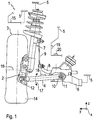
- a wheel suspension 1 of a vehicle can be seen, which comprises a vehicle wheel 3 rotatably mounted on a wheel carrier 2 and a suspension arm 4 in the form of a wishbone, by means of which the wheel carrier 2 is connected to a subframe 6 attached to a vehicle body 5, which is assigned to the vehicle body 5 becomes.
- the wheel suspension 1 further comprises a spring strut 7, by means of which the wheel carrier 2 is additionally connected to the vehicle body 5.
- a roll stabilizer 8 in the form of a torsion bar spring is mounted on the subframe 6, one end of which is connected to the spring strut 7 via a pendulum support 9.
- the suspension arm 4 is mounted on the auxiliary frame 6 at one end by means of a rubber bearing 10 so as to be pivotable about a pivot axis 11 and is mounted at the other end on the wheel carrier 2 by means of a ball joint 12.
- the vehicle wheel 3 comprises a rim 13 (see Fig. 2 ) and a tire 14 that sits on the rim 13.
- the vehicle body 5 further comprises a wheel house 15 in which the vehicle wheel 3 is arranged.
- a coordinate system x, y and z is shown, with the x-axis extending into the plane of the sheet representing a longitudinal direction of the vehicle, the y-axis representing a transverse direction of the vehicle and the z-axis representing a vertical direction of the vehicle.
- the pivot axis 11 runs in or approximately in the vehicle longitudinal direction x.
- the suspension arm 4 can thus be pivoted relative to the subframe 6 and / or to the vehicle body 5 in the direction of the arrow 17 about the pivot axis 11.
- a part of the rim 13 and part of the wheel house 15 is shown in a schematic representation, with a height h being shown, which describes the distance between the vehicle wheel 3 and the vehicle body 5 in or approximately in the vertical direction z of the vehicle.
- the height h is measured between a defined location of the vehicle wheel 3 and a defined location of the vehicle body 5.
- An acceleration sensor 18 is attached to the suspension arm 4 and is electrically connected to an evaluation device 19, which is preferably attached to the vehicle body 5.
- a reference sensor 20 designed as an acceleration sensor is attached to the vehicle body 5 and is electrically connected to the evaluation device 19.
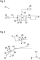
- the acceleration sensor 18, the reference sensor 20 and the evaluation device 19 are part of an in Fig. 3 schematically illustrated level measuring device 21 according to one embodiment.
- the evaluation device 19 also includes a microcontroller 22 and an electronic storage unit 23.
- the acceleration sensor 18 has a resiliently suspended seismic mass 24, which can be moved against spring force from a rest position in a measuring direction 25.
- the measuring direction 25 runs parallel to a suspension arm axis 26 assigned to the suspension arm 4, which runs perpendicular to the pivot axis 11.
- the suspension arm axis 26 runs through the kinematic center points of the rubber bearing 10 and ball joint 12. If the measuring direction 25 is not aligned perpendicular to the direction of the gravitational acceleration 27, the seismic mass 24 is deflected from its rest position due to gravity, which can be detected by the acceleration sensor 18 . It is thus possible to determine an angle of inclination which the measuring direction 25 includes with the direction of the acceleration due to gravity 27.
- the reference sensor 20 also has a resiliently suspended seismic mass 28, which can be moved in a measuring direction 29 from a rest position against spring force.
- the measuring direction 29 runs parallel to a reference axis 30 assigned to the vehicle body 5, which runs perpendicular to the pivot axis 11.
- the reference axis 30 runs in the vehicle transverse direction y and / or is parallel to a plane spanned by the vehicle longitudinal direction x and the vehicle transverse direction y. If the measuring direction 29 is not aligned perpendicular to the direction of the acceleration due to gravity 27, the seismic mass 28 is deflected from its rest position due to gravity, which can be detected by means of the reference sensor 20.
- an angle of inclination can be determined which the measuring direction 29 also includes the direction of the gravitational acceleration 27 includes. If the difference is formed from the angles of inclination, the result is the angle enclosed between the measuring directions 25 and 29, which characterizes the angle enclosed between the chassis link 4 and the vehicle body 5. Information about the position of the suspension arm 4 relative to the vehicle body 5 is thus available, from which the height h can be calculated.
- the evaluation device 19 thus calculates, in particular by means of the microcontroller 22, from a sensor signal 31 generated by the acceleration sensor 18 and a sensor signal 32 generated by the reference sensor 20, at least one angle information characterizing the angle enclosed between the chassis link 4 and the vehicle body 5 and puts this in particular into the memory unit 23.
- the evaluation device 19 calculates from the angle information, in particular by means of the microcontroller 22, height information 33 characterizing the height h and stores this in the memory unit 23.
- the evaluation device 19, in particular by means of the microcontroller 22, calculates from the sensor signals 31 and 32, preferably directly, the height information 33 characterizing the height h and stores it in the memory unit 23.
- a height level signal 34 characterizing the height level information 33 is generated and transmitted to a headlight leveling device 35, by means of which headlight leveling can be carried out by evaluating the leveling level signal 34.
- the ride height signal 34 can also be output to another control device of the vehicle.
- the ride height signal 34 is output to an active chassis control device, by means of which an active chassis control can be carried out by evaluating the ride height signal 34.
Landscapes
- Engineering & Computer Science (AREA)
- Mechanical Engineering (AREA)
- Physics & Mathematics (AREA)
- General Physics & Mathematics (AREA)
- Vehicle Body Suspensions (AREA)
Applications Claiming Priority (3)
| Application Number | Priority Date | Filing Date | Title |
|---|---|---|---|
| DE102016215418 | 2016-08-17 | ||
| DE102017207559.7A DE102017207559A1 (de) | 2016-08-17 | 2017-05-05 | Höhenstandmessvorrichtung für ein Fahrzeug |
| PCT/EP2017/067979 WO2018033321A1 (de) | 2016-08-17 | 2017-07-17 | Höhenstandmessvorrichtung für ein fahrzeug |
Publications (2)
| Publication Number | Publication Date |
|---|---|
| EP3500445A1 EP3500445A1 (de) | 2019-06-26 |
| EP3500445B1 true EP3500445B1 (de) | 2021-01-27 |
Family
ID=61082538
Family Applications (1)
| Application Number | Title | Priority Date | Filing Date |
|---|---|---|---|
| EP17762050.7A Active EP3500445B1 (de) | 2016-08-17 | 2017-07-17 | Höhenstandmessvorrichtung für ein fahrzeug |
Country Status (6)
| Country | Link |
|---|---|
| EP (1) | EP3500445B1 (enExample) |
| JP (1) | JP2019526481A (enExample) |
| KR (1) | KR102363031B1 (enExample) |
| CN (1) | CN109562666A (enExample) |
| DE (1) | DE102017207559A1 (enExample) |
| WO (1) | WO2018033321A1 (enExample) |
Families Citing this family (10)
| Publication number | Priority date | Publication date | Assignee | Title |
|---|---|---|---|---|
| DE102018210586B3 (de) * | 2018-06-28 | 2019-11-21 | Continental Automotive Gmbh | Verfahren und Vorrichtung zur automatischen Leuchtweitenregulierung einer Frontscheinwerfereinrichtung eines Fahrzeuges |
| PL3894808T3 (pl) * | 2018-12-14 | 2024-02-12 | Kistler Holding Ag | Kalibracja czujnika wim |
| US12138982B2 (en) * | 2020-09-24 | 2024-11-12 | Arnott T&P Holding, Llc | Suspension controller and sensor network for ride height control with air suspension |
| CN112248740B (zh) * | 2020-11-18 | 2025-04-29 | 石河子大学 | 自走式喷雾机悬架系统及其控制方法 |
| JP2023528115A (ja) * | 2021-04-29 | 2023-07-04 | 国志 蔡 | 角度計算システム及びその方法 |
| CN114801621A (zh) * | 2022-05-17 | 2022-07-29 | 长春市华通机械电器有限公司 | 一种底盘结构件的控制臂系统 |
| DE102022209305B3 (de) | 2022-09-07 | 2023-12-28 | Zf Friedrichshafen Ag | Messvorrichtung für ein Fahrzeug und Verfahren zum Betreiben einer solchen Messvorrichtung |
| DE102023207859A1 (de) * | 2023-08-16 | 2025-02-20 | Zf Friedrichshafen Ag | Lenkwinkelerfassungsvorrichtung |
| DE102023212217B3 (de) * | 2023-12-05 | 2025-02-27 | Zf Friedrichshafen Ag | Vorrichtung und Verfahren zur Höhenstandbestimmung |
| DE102023212211B3 (de) | 2023-12-05 | 2025-02-27 | Zf Friedrichshafen Ag | Vorrichtung und Verfahren zur Erfassung eines Neigungswinkels |
Family Cites Families (9)
| Publication number | Priority date | Publication date | Assignee | Title |
|---|---|---|---|---|
| JP3849829B2 (ja) * | 1998-04-27 | 2006-11-22 | 株式会社デンソー | 車高センサ及び車両用前照灯光軸調整装置 |
| NO322341B1 (no) * | 2002-09-25 | 2006-09-18 | Kongsberg Automotive Asa | System for avlesning av nivaendring i kjoretoy |
| DE10356402B4 (de) * | 2003-12-03 | 2005-12-15 | Zf Friedrichshafen Ag | Verfahren zur Bestimmung der Absolutposition von einem beweglichen Bauteil |
| EP1691994B1 (de) * | 2003-12-12 | 2009-07-15 | Continental Automotive GmbH | Bestimmung einer relativbewegung eines fahrwerks und eines fahrzeugaufbaus eines radfahrzeuges |
| DE102007021675A1 (de) * | 2007-05-09 | 2009-01-15 | Volkswagen Ag | Verfahren zur Steuerung der optischen Achse eines Fahrzeugscheinwerfers |
| DE102008052035A1 (de) * | 2008-10-16 | 2010-04-22 | Hella Kgaa Hueck & Co. | Verfahren und Sensoranordnung zur Erfassung der Federwege an der Vorder- und/oder Hinterachse eines Kraftfahrzeuges |
| JP2011168094A (ja) | 2010-02-16 | 2011-09-01 | Equos Research Co Ltd | 車両の制御値設定方法 |
| DE102010030406B4 (de) * | 2010-06-23 | 2017-10-26 | Zf Friedrichshafen Ag | Verbundlenkerachse für ein Fahrzeug |
| DE102015119129B4 (de) * | 2015-11-06 | 2021-06-24 | Knorr-Bremse Systeme für Nutzfahrzeuge GmbH | Vorrichtung und Verfahren zur Bestimmung der Höhe eines Fahrzeugfahrgestells |
-
2017
- 2017-05-05 DE DE102017207559.7A patent/DE102017207559A1/de not_active Ceased
- 2017-07-17 CN CN201780050189.7A patent/CN109562666A/zh active Pending
- 2017-07-17 JP JP2018567228A patent/JP2019526481A/ja not_active Withdrawn
- 2017-07-17 WO PCT/EP2017/067979 patent/WO2018033321A1/de not_active Ceased
- 2017-07-17 KR KR1020197007371A patent/KR102363031B1/ko active Active
- 2017-07-17 EP EP17762050.7A patent/EP3500445B1/de active Active
Non-Patent Citations (1)
| Title |
|---|
| None * |
Also Published As
| Publication number | Publication date |
|---|---|
| KR20190034674A (ko) | 2019-04-02 |
| JP2019526481A (ja) | 2019-09-19 |
| WO2018033321A1 (de) | 2018-02-22 |
| KR102363031B1 (ko) | 2022-02-17 |
| CN109562666A (zh) | 2019-04-02 |
| EP3500445A1 (de) | 2019-06-26 |
| DE102017207559A1 (de) | 2018-02-22 |
Similar Documents
| Publication | Publication Date | Title |
|---|---|---|
| EP3500445B1 (de) | Höhenstandmessvorrichtung für ein fahrzeug | |
| DE19904908C2 (de) | Einrichtung zur Abstandsbestimmung zwischen Fahrzeugaufbau und Fahrzeugrad | |
| DE102006001436B4 (de) | Verfahren zum Bestimmen wenigstens eines Bewegungszustands eines Fahrzeugaufbaus | |
| DE102005033237B4 (de) | Verfahren zur Bestimmung und Korrektur von Fehlorientierungen und Offsets der Sensoren einer Inertial Measurement Unit in einem Landfahrzeug | |
| DE102008040212A1 (de) | Radaufhängung für ein Fahrzeug | |
| WO2005056358A1 (de) | Bestimmung von dynamischen achsfasten und/oder radlasten eines radfahrzeuges | |
| DE102005012245B4 (de) | Radaufhängung für ein Fahrzeug | |
| DE112015006908T5 (de) | Fahrzeugbewegungsdetektionseinrichtung | |
| DE102004055856A1 (de) | Vorrichtung zur Schätzung der Schwerpunktlage eines Fahrzeugs | |
| WO2012045556A1 (de) | Verfahren zum ermitteln einer neigung eines fahrzeuges in fahrtrichtung | |
| EP1691994B1 (de) | Bestimmung einer relativbewegung eines fahrwerks und eines fahrzeugaufbaus eines radfahrzeuges | |
| DE102017001271B3 (de) | System und Verfahren zur Bestimmung eines Nickwinkels eines Fahrzeugs | |
| DE102020210979A1 (de) | Zentralgelenkvorrichtung für Fahrwerkskomponenten | |
| DE102015119129B4 (de) | Vorrichtung und Verfahren zur Bestimmung der Höhe eines Fahrzeugfahrgestells | |
| EP1592592B1 (de) | Verfahren zur erhöhung der fahrstabilität eines fahrzeugs | |
| DE102004059544B4 (de) | Radaufhängung für ein Fahrzeug | |
| DE102023212211B3 (de) | Vorrichtung und Verfahren zur Erfassung eines Neigungswinkels | |
| DE102004053236B4 (de) | Verfahren zur Ermittlung einer Längsbeschleunigung eines Kraftfahrzeuges | |
| DE102023212217B3 (de) | Vorrichtung und Verfahren zur Höhenstandbestimmung | |
| DE102017209142A1 (de) | Stabilisatoranordnung für Kraftfahrzeuge | |
| DE102024205866A1 (de) | Vorrichtung zur Erfassung eines Neigungswinkels | |
| DE102009006617A1 (de) | Verfahren zur Ermittlung eines Beladungszustandes eines Fahrzeuges | |
| DE102019218011A1 (de) | Verfahren und Vorrichtung zum situationsselektiven Stabilisieren eines Wankens eines Fahrzeugs | |
| DE102017122641A1 (de) | Verfahren zur Bestimmung eines hochfrequenten Anteils einer Fahrzeugdrehung und Verfahren zur Bestimmung des Einflusses eines hochfrequenten Anteils einer Nickbewegung sowie einer Wankbewegung eines Kraftfahrzeugs und Verfahren zur Bestimmung des Einflusses eines hochfrequenten Anteils einer Bewegung eines Kraftfahrzeugs auf die Bewegung einer Radaufhängung | |
| DE102007020594B4 (de) | Verfahren und Vorrichtung zum Ermitteln von Beschleunigungsschätzwerten in einem Fahrzeug |
Legal Events
| Date | Code | Title | Description |
|---|---|---|---|
| STAA | Information on the status of an ep patent application or granted ep patent |
Free format text: STATUS: UNKNOWN |
|
| STAA | Information on the status of an ep patent application or granted ep patent |
Free format text: STATUS: THE INTERNATIONAL PUBLICATION HAS BEEN MADE |
|
| PUAI | Public reference made under article 153(3) epc to a published international application that has entered the european phase |
Free format text: ORIGINAL CODE: 0009012 |
|
| STAA | Information on the status of an ep patent application or granted ep patent |
Free format text: STATUS: REQUEST FOR EXAMINATION WAS MADE |
|
| 17P | Request for examination filed |
Effective date: 20190115 |
|
| AK | Designated contracting states |
Kind code of ref document: A1 Designated state(s): AL AT BE BG CH CY CZ DE DK EE ES FI FR GB GR HR HU IE IS IT LI LT LU LV MC MK MT NL NO PL PT RO RS SE SI SK SM TR |
|
| AX | Request for extension of the european patent |
Extension state: BA ME |
|
| DAV | Request for validation of the european patent (deleted) | ||
| DAX | Request for extension of the european patent (deleted) | ||
| RIC1 | Information provided on ipc code assigned before grant |
Ipc: B60Q 1/12 20060101ALI20200630BHEP Ipc: B60Q 1/10 20060101ALI20200630BHEP Ipc: G01P 15/08 20060101ALI20200630BHEP Ipc: B60G 17/019 20060101AFI20200630BHEP |
|
| GRAP | Despatch of communication of intention to grant a patent |
Free format text: ORIGINAL CODE: EPIDOSNIGR1 |
|
| STAA | Information on the status of an ep patent application or granted ep patent |
Free format text: STATUS: GRANT OF PATENT IS INTENDED |
|
| INTG | Intention to grant announced |
Effective date: 20200904 |
|
| GRAS | Grant fee paid |
Free format text: ORIGINAL CODE: EPIDOSNIGR3 |
|
| GRAA | (expected) grant |
Free format text: ORIGINAL CODE: 0009210 |
|
| STAA | Information on the status of an ep patent application or granted ep patent |
Free format text: STATUS: THE PATENT HAS BEEN GRANTED |
|
| AK | Designated contracting states |
Kind code of ref document: B1 Designated state(s): AL AT BE BG CH CY CZ DE DK EE ES FI FR GB GR HR HU IE IS IT LI LT LU LV MC MK MT NL NO PL PT RO RS SE SI SK SM TR |
|
| REG | Reference to a national code |
Ref country code: GB Ref legal event code: FG4D Free format text: NOT ENGLISH |
|
| REG | Reference to a national code |
Ref country code: CH Ref legal event code: EP |
|
| REG | Reference to a national code |
Ref country code: AT Ref legal event code: REF Ref document number: 1358032 Country of ref document: AT Kind code of ref document: T Effective date: 20210215 |
|
| REG | Reference to a national code |
Ref country code: IE Ref legal event code: FG4D Free format text: LANGUAGE OF EP DOCUMENT: GERMAN |
|
| REG | Reference to a national code |
Ref country code: DE Ref legal event code: R096 Ref document number: 502017009254 Country of ref document: DE |
|
| REG | Reference to a national code |
Ref country code: NL Ref legal event code: MP Effective date: 20210127 |
|
| REG | Reference to a national code |
Ref country code: LT Ref legal event code: MG9D |
|
| PG25 | Lapsed in a contracting state [announced via postgrant information from national office to epo] |
Ref country code: LT Free format text: LAPSE BECAUSE OF FAILURE TO SUBMIT A TRANSLATION OF THE DESCRIPTION OR TO PAY THE FEE WITHIN THE PRESCRIBED TIME-LIMIT Effective date: 20210127 Ref country code: BG Free format text: LAPSE BECAUSE OF FAILURE TO SUBMIT A TRANSLATION OF THE DESCRIPTION OR TO PAY THE FEE WITHIN THE PRESCRIBED TIME-LIMIT Effective date: 20210427 Ref country code: FI Free format text: LAPSE BECAUSE OF FAILURE TO SUBMIT A TRANSLATION OF THE DESCRIPTION OR TO PAY THE FEE WITHIN THE PRESCRIBED TIME-LIMIT Effective date: 20210127 Ref country code: GR Free format text: LAPSE BECAUSE OF FAILURE TO SUBMIT A TRANSLATION OF THE DESCRIPTION OR TO PAY THE FEE WITHIN THE PRESCRIBED TIME-LIMIT Effective date: 20210428 Ref country code: HR Free format text: LAPSE BECAUSE OF FAILURE TO SUBMIT A TRANSLATION OF THE DESCRIPTION OR TO PAY THE FEE WITHIN THE PRESCRIBED TIME-LIMIT Effective date: 20210127 Ref country code: NO Free format text: LAPSE BECAUSE OF FAILURE TO SUBMIT A TRANSLATION OF THE DESCRIPTION OR TO PAY THE FEE WITHIN THE PRESCRIBED TIME-LIMIT Effective date: 20210427 Ref country code: PT Free format text: LAPSE BECAUSE OF FAILURE TO SUBMIT A TRANSLATION OF THE DESCRIPTION OR TO PAY THE FEE WITHIN THE PRESCRIBED TIME-LIMIT Effective date: 20210527 |
|
| PG25 | Lapsed in a contracting state [announced via postgrant information from national office to epo] |
Ref country code: PL Free format text: LAPSE BECAUSE OF FAILURE TO SUBMIT A TRANSLATION OF THE DESCRIPTION OR TO PAY THE FEE WITHIN THE PRESCRIBED TIME-LIMIT Effective date: 20210127 Ref country code: LV Free format text: LAPSE BECAUSE OF FAILURE TO SUBMIT A TRANSLATION OF THE DESCRIPTION OR TO PAY THE FEE WITHIN THE PRESCRIBED TIME-LIMIT Effective date: 20210127 Ref country code: RS Free format text: LAPSE BECAUSE OF FAILURE TO SUBMIT A TRANSLATION OF THE DESCRIPTION OR TO PAY THE FEE WITHIN THE PRESCRIBED TIME-LIMIT Effective date: 20210127 Ref country code: SE Free format text: LAPSE BECAUSE OF FAILURE TO SUBMIT A TRANSLATION OF THE DESCRIPTION OR TO PAY THE FEE WITHIN THE PRESCRIBED TIME-LIMIT Effective date: 20210127 |
|
| PG25 | Lapsed in a contracting state [announced via postgrant information from national office to epo] |
Ref country code: IS Free format text: LAPSE BECAUSE OF FAILURE TO SUBMIT A TRANSLATION OF THE DESCRIPTION OR TO PAY THE FEE WITHIN THE PRESCRIBED TIME-LIMIT Effective date: 20210527 |
|
| REG | Reference to a national code |
Ref country code: DE Ref legal event code: R097 Ref document number: 502017009254 Country of ref document: DE |
|
| PG25 | Lapsed in a contracting state [announced via postgrant information from national office to epo] |
Ref country code: SM Free format text: LAPSE BECAUSE OF FAILURE TO SUBMIT A TRANSLATION OF THE DESCRIPTION OR TO PAY THE FEE WITHIN THE PRESCRIBED TIME-LIMIT Effective date: 20210127 Ref country code: CZ Free format text: LAPSE BECAUSE OF FAILURE TO SUBMIT A TRANSLATION OF THE DESCRIPTION OR TO PAY THE FEE WITHIN THE PRESCRIBED TIME-LIMIT Effective date: 20210127 Ref country code: EE Free format text: LAPSE BECAUSE OF FAILURE TO SUBMIT A TRANSLATION OF THE DESCRIPTION OR TO PAY THE FEE WITHIN THE PRESCRIBED TIME-LIMIT Effective date: 20210127 |
|
| PG25 | Lapsed in a contracting state [announced via postgrant information from national office to epo] |
Ref country code: RO Free format text: LAPSE BECAUSE OF FAILURE TO SUBMIT A TRANSLATION OF THE DESCRIPTION OR TO PAY THE FEE WITHIN THE PRESCRIBED TIME-LIMIT Effective date: 20210127 Ref country code: DK Free format text: LAPSE BECAUSE OF FAILURE TO SUBMIT A TRANSLATION OF THE DESCRIPTION OR TO PAY THE FEE WITHIN THE PRESCRIBED TIME-LIMIT Effective date: 20210127 Ref country code: SK Free format text: LAPSE BECAUSE OF FAILURE TO SUBMIT A TRANSLATION OF THE DESCRIPTION OR TO PAY THE FEE WITHIN THE PRESCRIBED TIME-LIMIT Effective date: 20210127 |
|
| PLBE | No opposition filed within time limit |
Free format text: ORIGINAL CODE: 0009261 |
|
| STAA | Information on the status of an ep patent application or granted ep patent |
Free format text: STATUS: NO OPPOSITION FILED WITHIN TIME LIMIT |
|
| 26N | No opposition filed |
Effective date: 20211028 |
|
| PG25 | Lapsed in a contracting state [announced via postgrant information from national office to epo] |
Ref country code: AL Free format text: LAPSE BECAUSE OF FAILURE TO SUBMIT A TRANSLATION OF THE DESCRIPTION OR TO PAY THE FEE WITHIN THE PRESCRIBED TIME-LIMIT Effective date: 20210127 Ref country code: ES Free format text: LAPSE BECAUSE OF FAILURE TO SUBMIT A TRANSLATION OF THE DESCRIPTION OR TO PAY THE FEE WITHIN THE PRESCRIBED TIME-LIMIT Effective date: 20210127 |
|
| PG25 | Lapsed in a contracting state [announced via postgrant information from national office to epo] |
Ref country code: SI Free format text: LAPSE BECAUSE OF FAILURE TO SUBMIT A TRANSLATION OF THE DESCRIPTION OR TO PAY THE FEE WITHIN THE PRESCRIBED TIME-LIMIT Effective date: 20210127 |
|
| REG | Reference to a national code |
Ref country code: CH Ref legal event code: PL |
|
| GBPC | Gb: european patent ceased through non-payment of renewal fee |
Effective date: 20210717 |
|
| PG25 | Lapsed in a contracting state [announced via postgrant information from national office to epo] |
Ref country code: MC Free format text: LAPSE BECAUSE OF FAILURE TO SUBMIT A TRANSLATION OF THE DESCRIPTION OR TO PAY THE FEE WITHIN THE PRESCRIBED TIME-LIMIT Effective date: 20210127 |
|
| REG | Reference to a national code |
Ref country code: BE Ref legal event code: MM Effective date: 20210731 |
|
| PG25 | Lapsed in a contracting state [announced via postgrant information from national office to epo] |
Ref country code: LI Free format text: LAPSE BECAUSE OF NON-PAYMENT OF DUE FEES Effective date: 20210731 Ref country code: IT Free format text: LAPSE BECAUSE OF FAILURE TO SUBMIT A TRANSLATION OF THE DESCRIPTION OR TO PAY THE FEE WITHIN THE PRESCRIBED TIME-LIMIT Effective date: 20210127 Ref country code: GB Free format text: LAPSE BECAUSE OF NON-PAYMENT OF DUE FEES Effective date: 20210717 Ref country code: CH Free format text: LAPSE BECAUSE OF NON-PAYMENT OF DUE FEES Effective date: 20210731 |
|
| PG25 | Lapsed in a contracting state [announced via postgrant information from national office to epo] |
Ref country code: IS Free format text: LAPSE BECAUSE OF FAILURE TO SUBMIT A TRANSLATION OF THE DESCRIPTION OR TO PAY THE FEE WITHIN THE PRESCRIBED TIME-LIMIT Effective date: 20210527 Ref country code: LU Free format text: LAPSE BECAUSE OF NON-PAYMENT OF DUE FEES Effective date: 20210717 Ref country code: FR Free format text: LAPSE BECAUSE OF NON-PAYMENT OF DUE FEES Effective date: 20210731 |
|
| PG25 | Lapsed in a contracting state [announced via postgrant information from national office to epo] |
Ref country code: IE Free format text: LAPSE BECAUSE OF NON-PAYMENT OF DUE FEES Effective date: 20210717 Ref country code: BE Free format text: LAPSE BECAUSE OF NON-PAYMENT OF DUE FEES Effective date: 20210731 |
|
| PG25 | Lapsed in a contracting state [announced via postgrant information from national office to epo] |
Ref country code: CY Free format text: LAPSE BECAUSE OF FAILURE TO SUBMIT A TRANSLATION OF THE DESCRIPTION OR TO PAY THE FEE WITHIN THE PRESCRIBED TIME-LIMIT Effective date: 20210127 Ref country code: NL Free format text: LAPSE BECAUSE OF NON-PAYMENT OF DUE FEES Effective date: 20210127 |
|
| P01 | Opt-out of the competence of the unified patent court (upc) registered |
Effective date: 20230528 |
|
| PG25 | Lapsed in a contracting state [announced via postgrant information from national office to epo] |
Ref country code: HU Free format text: LAPSE BECAUSE OF FAILURE TO SUBMIT A TRANSLATION OF THE DESCRIPTION OR TO PAY THE FEE WITHIN THE PRESCRIBED TIME-LIMIT; INVALID AB INITIO Effective date: 20170717 |
|
| REG | Reference to a national code |
Ref country code: AT Ref legal event code: MM01 Ref document number: 1358032 Country of ref document: AT Kind code of ref document: T Effective date: 20220717 |
|
| PG25 | Lapsed in a contracting state [announced via postgrant information from national office to epo] |
Ref country code: AT Free format text: LAPSE BECAUSE OF NON-PAYMENT OF DUE FEES Effective date: 20220717 |
|
| PG25 | Lapsed in a contracting state [announced via postgrant information from national office to epo] |
Ref country code: MK Free format text: LAPSE BECAUSE OF FAILURE TO SUBMIT A TRANSLATION OF THE DESCRIPTION OR TO PAY THE FEE WITHIN THE PRESCRIBED TIME-LIMIT Effective date: 20210127 |
|
| PG25 | Lapsed in a contracting state [announced via postgrant information from national office to epo] |
Ref country code: TR Free format text: LAPSE BECAUSE OF FAILURE TO SUBMIT A TRANSLATION OF THE DESCRIPTION OR TO PAY THE FEE WITHIN THE PRESCRIBED TIME-LIMIT Effective date: 20210127 |
|
| PG25 | Lapsed in a contracting state [announced via postgrant information from national office to epo] |
Ref country code: MT Free format text: LAPSE BECAUSE OF FAILURE TO SUBMIT A TRANSLATION OF THE DESCRIPTION OR TO PAY THE FEE WITHIN THE PRESCRIBED TIME-LIMIT Effective date: 20210127 |
|
| PGFP | Annual fee paid to national office [announced via postgrant information from national office to epo] |
Ref country code: DE Payment date: 20250604 Year of fee payment: 9 |