EP3499089B1 - Kugelumlenkung eines kugelgewindetriebes - Google Patents
Kugelumlenkung eines kugelgewindetriebes Download PDFInfo
- Publication number
- EP3499089B1 EP3499089B1 EP17207232.4A EP17207232A EP3499089B1 EP 3499089 B1 EP3499089 B1 EP 3499089B1 EP 17207232 A EP17207232 A EP 17207232A EP 3499089 B1 EP3499089 B1 EP 3499089B1
- Authority
- EP
- European Patent Office
- Prior art keywords
- spindle nut
- upper shell
- ball
- shell
- opening
- Prior art date
- Legal status (The legal status is an assumption and is not a legal conclusion. Google has not performed a legal analysis and makes no representation as to the accuracy of the status listed.)
- Active
Links
Images


Classifications
-
- F—MECHANICAL ENGINEERING; LIGHTING; HEATING; WEAPONS; BLASTING
- F16—ENGINEERING ELEMENTS AND UNITS; GENERAL MEASURES FOR PRODUCING AND MAINTAINING EFFECTIVE FUNCTIONING OF MACHINES OR INSTALLATIONS; THERMAL INSULATION IN GENERAL
- F16H—GEARING
- F16H25/00—Gearings comprising primarily only cams, cam-followers and screw-and-nut mechanisms
- F16H25/18—Gearings comprising primarily only cams, cam-followers and screw-and-nut mechanisms for conveying or interconverting oscillating or reciprocating motions
- F16H25/20—Screw mechanisms
- F16H25/22—Screw mechanisms with balls, rollers, or similar members between the co-operating parts; Elements essential to the use of such members
- F16H25/2204—Screw mechanisms with balls, rollers, or similar members between the co-operating parts; Elements essential to the use of such members with balls
- F16H25/2214—Screw mechanisms with balls, rollers, or similar members between the co-operating parts; Elements essential to the use of such members with balls with elements for guiding the circulating balls
- F16H25/2223—Cross over deflectors between adjacent thread turns, e.g. S-form deflectors connecting neighbouring threads
-
- F—MECHANICAL ENGINEERING; LIGHTING; HEATING; WEAPONS; BLASTING
- F16—ENGINEERING ELEMENTS AND UNITS; GENERAL MEASURES FOR PRODUCING AND MAINTAINING EFFECTIVE FUNCTIONING OF MACHINES OR INSTALLATIONS; THERMAL INSULATION IN GENERAL
- F16H—GEARING
- F16H25/00—Gearings comprising primarily only cams, cam-followers and screw-and-nut mechanisms
- F16H25/18—Gearings comprising primarily only cams, cam-followers and screw-and-nut mechanisms for conveying or interconverting oscillating or reciprocating motions
- F16H25/20—Screw mechanisms
- F16H25/22—Screw mechanisms with balls, rollers, or similar members between the co-operating parts; Elements essential to the use of such members
- F16H25/2204—Screw mechanisms with balls, rollers, or similar members between the co-operating parts; Elements essential to the use of such members with balls
- F16H25/2214—Screw mechanisms with balls, rollers, or similar members between the co-operating parts; Elements essential to the use of such members with balls with elements for guiding the circulating balls
- F16H25/2228—Screw mechanisms with balls, rollers, or similar members between the co-operating parts; Elements essential to the use of such members with balls with elements for guiding the circulating balls the device for circulation forming a part of the screw member
Definitions
- the present invention relates to a ball screw drive, in particular a greatly simplified ball deflection device for a ball screw drive.
- a rolling screw drive with balls as rolling elements is usually referred to as a ball screw or ball screw drive (KGT).
- KGT ball screw or ball screw drive
- a KGT works as a helical gear, the reduction or translation of which is determined by the dimensioning of the threaded spindle, more precisely by the pitch of the thread.
- KGTs are also increasingly being used as longitudinal drives in areas where previously hydraulic systems were mostly used, e.g. in presses, injection molding machines and power steering.
- KGT also play an increasing role in electromechanical and electro-hydraulic brake systems, where KGT are used as a replacement for hydraulic brake cylinders or in parallel with known brake systems as an actuating element of a brake assistance system.
- a state-of-the-art KGT is WO 2014/184154 shown and in figure 1 pictured.
- the main components of the KGT 10 include a threaded spindle 12 and a spindle nut 14 surrounding this spindle. Balls rotate between these two components during operation, with the threads of the threaded spindle 12 and the spindle nut 14 being designed to be complementary and coordinated in such a way that they act as a Ball guides work.
- the spindle nut 14 consists of a nut body which has an opening 17 for a ball deflection device 15, 16.
- This ball deflection device 15, 16 has the task of lifting the balls out of the ball guide between the spindle nut 14 and the threaded spindle 12 at a first point and returning them to a second point.
- the ball return thus represents a bypass that bridges several threads of the nut-spindle system. This creates a closed circulation path for the balls of the KGT 10.
- the ball deflection device 15, 16 is essentially made in two parts.
- the first part 16 has a substantially U-shape and is designed in cross section at least partially semi-tubular.
- the second part 15 supplements the first part 16 in such a way that a tubular contour is formed at least at the ends of the deflection device.
- the assembly process for the ball deflection of this KGT type is such that the first part 16 of the ball deflection is inserted into the opening 17 of the spindle nut 14, then the second part 15 is added so that the second part is arranged radially further outwards than the first Part. By sliding over a sleeve 18, the first (16) and second (15) part of the ball deflection are secured.
- the ball deflection in a KGT is a very complex component, both in terms of manufacturing and assembly costs. Disadvantage of the prior art shown is therefore the design with two parts plus a locking sleeve.
- the sleeve must exert a defined force on the ball deflection device 15,16, which must not be too low, because insufficient support does not guarantee reliable ball guidance. Conversely, too much holding force can deform the ball return channel and affect the function of the KGT as a whole.
- the sleeve must be pushed over during assembly in a controlled manner so that the components 15 and 16 are not displaced or damaged.
- the document WO 2016/190 145 shows a ball deflection for a ball screw.
- the ball deflection is made in one piece and is bent in the middle in an opening of the spindle nut for assembly.
- the deflection is held in the opening by lugs that engage in a circumferential groove.
- the central kink is stiffened by fusing two components together.
- the object of the present invention is therefore to improve the state of the art with the aim of simplifying the construction while at the same time increasing the safety of assembly.
- the present invention solves this problem by replacing the sleeve 18 and simplifying the construction of the ball screw components according to claim 1.
- a spindle nut 14 as in the present invention through addressed has, as is known in the prior art, an internal thread which - together with the complementarily designed ball thread of a threaded spindle 12 - lead the balls in the ball grooves between spindle and nut.
- a ball deflection channel 28 In order to fulfill the function of a KGT, a ball deflection channel 28 must be created, which allows the balls of a KGT to return between two defined thread positions of the spindle nut. Only one or more windings can be bridged.
- KGT can have one or more ball deflection channels.
- KGT can have one or more ball deflection channels.
- it is customary and known to provide one or more openings in the nut body 19 of the spindle nut 14 .
- a slot-like opening is used for each ball deflection, at the longitudinal ends of which the nut body 19 is broken radially inwards and the ball circulation groove 20 of the spindle nut thus has two openings. Between these two openings, the opening 17 in the nut body 19 is designed as a ditch, which is worked out at least deep enough for the balls and the components of the ball deflection channel 28 to find space for this.
- a ball screw includes a threaded spindle 12 and a spindle nut 14 which encloses the threaded spindle 12 coaxially at least partially.
- a large number of balls runs in the space between the threaded spindle 12 and the spindle nut 14 .
- An opening 17 in the lateral surface of the spindle nut 14 accommodates a ball deflection device, which is designed in at least two parts and includes an upper shell 26 and a lower shell 25 .
- the lower shell 26 is arranged radially on the inside closer to the longitudinal axis of the spindle nut than the upper shell 25.
- the lower shell has an essentially half-shell contour.
- half-shell means the design as a "pipe divided lengthwise", whereby the division does not have to be in half.
- a rather flat design of the lower shell can be sufficient or preferred, similar to a channel.
- the upper shell 26 and lower shell 25 are fastened in the spindle nut 14 without further, discrete mechanical fastening means.
- the arrangement of lower shell 26 and upper shell 25 mounted in the spindle nut 14 will preferably not protrude beyond the outer contour predetermined by the spindle nut.
- discrete mechanical fasteners means that no screws, additional clamps and aids such as sleeves, brackets, etc. are required to functionally complete the ball deflection.
- connection between the upper shell 26 and the spindle nut 14 is instead made by a locking mechanism, a clip mechanism.
- a spring element 30 is provided on the upper shell 26 in the mounted state engages in a groove 32 in the side wall of the opening 17 in the spindle nut 14 and secures the upper shell 26 in a defined position in the opening 17.
- the groove or, alternatively, a longitudinal groove, wall opening or undercut can be introduced when the opening 17 is manufactured.
- the lower shell 25 is preferably designed as a molded part, as a deep-drawn part, as a stamped or embossed part or as an injection-molded part.
- the preferred choice of material is sheet steel, but high-strength plastics could also be used.
- the lower shell will have elements at the ends which, when installed, protrude into the ball circulation between the nut and spindle and enable the balls to be lifted out or returned. These can be tongue-like or spoon-like end sections that facilitate low-friction deflection of the ball.
- connection between the lower shell 25 and the spindle nut 14 could take the form of welding, caulking, clamping, spot welding or laser welding (design variant not claimed).
- the design of the upper shell can be different, both in terms of technical design and the choice of material.
- this is designed as a molded part, as a deep-drawn part, a stamped or embossed part or as an injection-molded part made of metal or plastic.
- the upper shell 26 and spindle nut 14 could preferably be connected by welding, caulking, clamping, spot welding or laser welding (design variant not claimed). This fulfills the feature "fixed without further, discrete mechanical fastening means".
- the opening 17 could have side walls which are conically inclined inwards towards the outer surface of the spindle nut 14, so that the bottom of the opening has a greater clear width than the edge of the opening 17 on the surface of the spindle nut.
- a clamping effect could thus be achieved by means of a complementary design of the upper shell, which likewise does not require any further mechanical fastening means (design variant not claimed).
- a further simplification proposed by the invention consists in not designing the ball deflection channel in such a way that the upper shell and lower shell form a closed tube or a closed tunnel.
- the upper shell and lower shell can be designed so that they only form a contoured roof and base and the side walls of the opening 17 serve directly as guide aids for the balls.
- the ball deflection channel 28 is formed at least in sections by the upper shell 26, the lower shell 25 and the side walls of the opening 17.
- the upper shell 26 can be made of plastic.
- this plastic part can be designed in such a way that it is largely modeled on a sheet metal part in terms of function and structure.
- the upper shell can also be designed or expanded in such a way that it encloses the spindle nut and thus forms the final surface of the spindle nut.
- "enclose” can mean either a partial or a complete surrounding of the spindle nut.
- This expanded upper shell 40 would be in one piece, that is, in the assembled state, the upper part of the ball deflection unit and the enclosing of the spindle nut form an inseparable unit. In this version, too, the ball deflection does not protrude beyond the final outer contour of the nut body, so this feature is retained.
- This embodiment could be implemented in such a way that an insert part, which comes close to the upper shell 26 as described above, is placed in the opening 17 . It closes off the ball deflection channel 28 and/or the opening 17 to the outside.
- the one-piece, expanded upper shell (40) is formed integrally by subsequent overmoulding of the spindle nut 14 .
- the insert would preferably be designed in such a way that the most intimate, secure connection possible with the plastic can be achieved during overmolding.
- the expanded upper shell could be manufactured in one piece as a separate component, and in this case also has the functional elements that are to be provided by the upper shell of the ball deflection unit.
- the ball circulation would be completed by pushing it onto a spindle nut 14 with the preassembled elements of the lower shell.
- the fixation in a target position can be achieved, for example, by the functional elements snapping into the opening 17 and thus ensuring a firm seat of the further upper shell 40.
- an upper shell 26 is placed in the opening 17 in a desired position. If the upper shell 26 is formed as a sheet metal part or as a corresponding plastic part, it can be attached to the spindle nut 14 by welding, caulking, clamping, spot welding or laser welding without any further discrete, mechanical fastening means.
- an extended plastic upper shell 40 can be provided which is mounted by simply sliding it onto the spindle nut 14 .
- the outer contour of the spindle nut is thus defined by the upper shell or extended upper shell.
- an upper shell 26 can have a functional element designed as a spring element 30 and a groove 32 (longitudinal groove, undercut, wall opening) can be provided in the opening 17 of the spindle nut 14 at the corresponding desired position.
- This upper shell can be pushed into the opening 17 in the spindle nut 14 until the spring element 30 engages in a locking manner in the groove 32 and the upper shell 26 is thus held in a defined position.
- the upper shell 26 can be made of plastic so that it can be deformed elastically and thus fit into the conical opening 17 in the spindle nut 14 be inserted so that a press fit is achieved in the target end position. By temporarily pressing together, the upper shell can temporarily pass through the opening that is narrower on the surface and can be mounted in this way.
- the upper shell 26 made of plastic or the insert part will be a semi-finished product and the partially assembled ball screw will be inserted into a tool of a plastic injection molding machine.
- the tool encloses the spindle nut 14 at least partially.
- the spindle nut is then overmoulded, as a result of which the upper shell 26 becomes an integral part of an extended upper shell 40 .
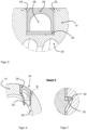
- figure 1 shows a KGT 10 according to the prior art and has already been explained above.
- figure 2 serves to define the cutting planes of the Figures 3-9 to understand better.
- the position of a cross-sectional plane and an oblique section plane are indicated.
- the oblique cutting plane S is designed to intersect a ball deflection channel running in an opening 17 lengthwise.
- figure 3 shows an embodiment of an inventive KGT with a spindle nut 14 in the oblique section S, which also shows the ball grooves 20.
- a ball deflection without a sleeve 18 is mounted in the opening 17, it forms the ball deflection channel 28.
- the lower shell 25 is a half-shell design as a relatively flat component.
- the upper shell 26 is also shown as a flat sheet metal part in FIG. The longitudinal ends are supported on projections incorporated in the opening.
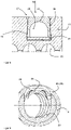
- figure 4 shows this variant in a top view from the outside.
- the upper shell(s) 26 cover the opening(s) 17. According to the invention, no further safety brackets, screw connections or safety sleeves are necessary.
- figure 5 shows the fastening type "caulking" in cross section.
- a relatively flat lower shell 15 and an upper shell 26 with a tunnel profile for the ball deflection channel 28 are arranged in the opening 17 in the spindle nut 14 .
- the staking operation has formed two projections, lugs or ridges 22, 24 at the edge of the opening which secure the ball link in place.
- FIGS. 6 and 7 show the type of attachment with a clip or spring element 30 in a groove 32.
- the direction of assembly or insertion is indicated by an arrow 34. Locking occurs when the spring element 30 can snap into the groove 32 .
- figure 8 12 illustrates the way in which a combination of lower shell 25 and upper shell 26 is fastened in an opening 17 with side walls 36, 38 tapering upwards (radially outwards). The press fit of the upper shell 26 that is achieved can be clearly seen.
- figure 9 shows a ball nut 14 overmoulded with plastic, which thus receives an expanded upper shell 40 .
- the lower shell 25 is installed as described above, while the upper half of the ball circulating channel 28 is formed in one piece by the injection molding process, in which an inserted semi-finished product or insert has specified the upper shell.
Landscapes
- Engineering & Computer Science (AREA)
- General Engineering & Computer Science (AREA)
- Mechanical Engineering (AREA)
- Transmission Devices (AREA)
- Pens And Brushes (AREA)
Priority Applications (5)
| Application Number | Priority Date | Filing Date | Title |
|---|---|---|---|
| PL17207232.4T PL3499089T3 (pl) | 2017-12-14 | 2017-12-14 | Mechanizm śrubowo-toczny z kulkami |
| ES17207232T ES2941499T3 (es) | 2017-12-14 | 2017-12-14 | Deflexión de bola de un husillo a bolas |
| EP17207232.4A EP3499089B1 (de) | 2017-12-14 | 2017-12-14 | Kugelumlenkung eines kugelgewindetriebes |
| US16/220,559 US11572937B2 (en) | 2017-12-14 | 2018-12-14 | Ball deflector for a ball screw |
| CN201811529167.1A CN109958743A (zh) | 2017-12-14 | 2018-12-14 | 滚珠丝杆传动装置的滚珠换向装置及其装配方法 |
Applications Claiming Priority (1)
| Application Number | Priority Date | Filing Date | Title |
|---|---|---|---|
| EP17207232.4A EP3499089B1 (de) | 2017-12-14 | 2017-12-14 | Kugelumlenkung eines kugelgewindetriebes |
Publications (2)
| Publication Number | Publication Date |
|---|---|
| EP3499089A1 EP3499089A1 (de) | 2019-06-19 |
| EP3499089B1 true EP3499089B1 (de) | 2023-03-08 |
Family
ID=60673545
Family Applications (1)
| Application Number | Title | Priority Date | Filing Date |
|---|---|---|---|
| EP17207232.4A Active EP3499089B1 (de) | 2017-12-14 | 2017-12-14 | Kugelumlenkung eines kugelgewindetriebes |
Country Status (5)
| Country | Link |
|---|---|
| US (1) | US11572937B2 (pl) |
| EP (1) | EP3499089B1 (pl) |
| CN (1) | CN109958743A (pl) |
| ES (1) | ES2941499T3 (pl) |
| PL (1) | PL3499089T3 (pl) |
Families Citing this family (2)
| Publication number | Priority date | Publication date | Assignee | Title |
|---|---|---|---|---|
| DE102015214856B4 (de) * | 2015-08-04 | 2017-07-06 | Schaeffler Technologies AG & Co. KG | Kugelgewindetrieb |
| PL3971448T3 (pl) * | 2020-09-22 | 2023-06-26 | SFS Group International AG | Nakrętka śruby pociągowej do napędu mechanizmu śrubowo-tocznego |
Citations (4)
| Publication number | Priority date | Publication date | Assignee | Title |
|---|---|---|---|---|
| US20120192668A1 (en) * | 2011-01-28 | 2012-08-02 | Po-Chuan Hsu | Deflector for ball screw |
| WO2014184154A1 (de) * | 2013-05-15 | 2014-11-20 | Sfs Intec Holding Ag | Kugelgewindetrieb |
| JP2015081636A (ja) * | 2013-10-22 | 2015-04-27 | 日本精工株式会社 | ボールねじ |
| EP3203117A1 (en) * | 2014-10-01 | 2017-08-09 | Kuroda Precision Industries Ltd. | Ball screw mechanism deflector and ball screw mechanism |
Family Cites Families (23)
| Publication number | Priority date | Publication date | Assignee | Title |
|---|---|---|---|---|
| GB1436693A (en) * | 1972-07-13 | 1976-05-19 | Csepeli Szerszamgepgyar | Double nut pre-loadab le screw mechanism |
| CA2035841C (en) | 1990-02-22 | 1996-02-13 | Harry B. Demopoulos | Storage-stable glucosamine sulphate oral dosage forms and methods for their manufacture |
| JP2595551Y2 (ja) * | 1993-05-31 | 1999-05-31 | 日本精工株式会社 | 内部循環式ボールねじ |
| JPH07174205A (ja) * | 1993-12-21 | 1995-07-11 | Toyota Motor Corp | ボールねじおよびボールねじ組立装置 |
| DE10011383B4 (de) * | 2000-03-09 | 2005-08-25 | Rexroth Star Gmbh | Wälzkörpergewindetrieb |
| JP3878068B2 (ja) * | 2002-06-26 | 2007-02-07 | 株式会社ジェイテクト | デフレクタ式ボールスクリュー装置及びその製造方法 |
| JP4029740B2 (ja) * | 2003-02-18 | 2008-01-09 | 日本精工株式会社 | ボールねじ用循環こまの製造方法及び循環こま並びにボールねじ |
| JP4582639B2 (ja) * | 2005-02-14 | 2010-11-17 | Ntn株式会社 | 電動リニアアクチュエータ |
| JP4730940B2 (ja) * | 2005-03-15 | 2011-07-20 | Ntn株式会社 | ボールねじ |
| JP4885691B2 (ja) * | 2006-11-28 | 2012-02-29 | 株式会社ショーワ | ボールナットのボール循環溝構造 |
| JP4941151B2 (ja) * | 2007-07-23 | 2012-05-30 | 日本精工株式会社 | ボールねじ装置 |
| DE112008003181B4 (de) * | 2007-11-30 | 2023-10-12 | Thk Co., Ltd. | Rollengewindetrieb |
| US20110303036A1 (en) * | 2009-01-06 | 2011-12-15 | Hiwin Technologies Corp. | Ball return device for ball screw device |
| DE202011001752U1 (de) * | 2011-01-20 | 2011-05-05 | Hiwin Technologies Corp. | Deflektor für einen Kugelgewindetrieb |
| JP5411313B2 (ja) * | 2012-04-27 | 2014-02-12 | 黒田精工株式会社 | ボールねじ |
| DE102013208441B4 (de) * | 2013-05-08 | 2023-08-17 | Robert Bosch Gmbh | Kugelgewindetrieb |
| JP6151161B2 (ja) * | 2013-11-29 | 2017-06-21 | 株式会社ショーワ | ボールねじおよびパワーステアリング装置 |
| JP2016017544A (ja) * | 2014-07-07 | 2016-02-01 | 日本精工株式会社 | 駒式ボールねじ |
| KR101747646B1 (ko) * | 2014-08-12 | 2017-06-14 | 구로다 세이코 가부시키가이샤 | 볼 나사 |
| JP6533663B2 (ja) * | 2015-01-19 | 2019-06-19 | 株式会社ショーワ | ボールねじおよび操舵装置 |
| JP6577195B2 (ja) * | 2015-02-04 | 2019-09-18 | Ntn株式会社 | 駒式ボールねじの製造方法 |
| JP6472330B2 (ja) * | 2015-05-28 | 2019-02-20 | 株式会社エンプラス | 駒式ボールねじの駒の固定構造 |
| CN105909745B (zh) * | 2016-06-13 | 2018-05-11 | 宁波海迈克精密机械制造有限公司 | 一种滚珠丝杠副 |
-
2017
- 2017-12-14 PL PL17207232.4T patent/PL3499089T3/pl unknown
- 2017-12-14 EP EP17207232.4A patent/EP3499089B1/de active Active
- 2017-12-14 ES ES17207232T patent/ES2941499T3/es active Active
-
2018
- 2018-12-14 US US16/220,559 patent/US11572937B2/en active Active
- 2018-12-14 CN CN201811529167.1A patent/CN109958743A/zh active Pending
Patent Citations (4)
| Publication number | Priority date | Publication date | Assignee | Title |
|---|---|---|---|---|
| US20120192668A1 (en) * | 2011-01-28 | 2012-08-02 | Po-Chuan Hsu | Deflector for ball screw |
| WO2014184154A1 (de) * | 2013-05-15 | 2014-11-20 | Sfs Intec Holding Ag | Kugelgewindetrieb |
| JP2015081636A (ja) * | 2013-10-22 | 2015-04-27 | 日本精工株式会社 | ボールねじ |
| EP3203117A1 (en) * | 2014-10-01 | 2017-08-09 | Kuroda Precision Industries Ltd. | Ball screw mechanism deflector and ball screw mechanism |
Also Published As
| Publication number | Publication date |
|---|---|
| PL3499089T3 (pl) | 2023-05-22 |
| US11572937B2 (en) | 2023-02-07 |
| ES2941499T3 (es) | 2023-05-23 |
| US20190186606A1 (en) | 2019-06-20 |
| CN109958743A (zh) | 2019-07-02 |
| EP3499089A1 (de) | 2019-06-19 |
Similar Documents
| Publication | Publication Date | Title |
|---|---|---|
| EP3698055B1 (de) | Toleranzausgleichsanordnung | |
| EP3717786B1 (de) | Toleranzausgleichsanordnung mit klemmsicherung | |
| EP1626185A1 (de) | Einstelleinheit zum Einstellen des Abstandes zwischen zwei Bauteilen | |
| DE102006004678A1 (de) | Montageeinheit für die Befestigungsöse eines Gurtschlosses | |
| EP3721097B1 (de) | Befestigungsanordnung mit winkelausgleichsfunktion | |
| EP3499089B1 (de) | Kugelumlenkung eines kugelgewindetriebes | |
| DE102005047390B4 (de) | Trägerrahmen, insbesondere für Dachsysteme im Kraftfahrzeugbereich | |
| EP3809013B1 (de) | Kugelgewindetrieb und montageverfahren | |
| DE102021118243A1 (de) | Steuerventilbaugruppe eines verstellers mit variabler nockenwellensteuerung | |
| EP2946988B1 (de) | Bauteilgruppe zum zusammenfügen von fahrzeugteilen | |
| EP1659268A1 (de) | Tassenstössel für eine Brennkraftmaschine | |
| DE102017127404B4 (de) | Kugelgewindetrieb | |
| EP1213186B1 (de) | Vorrichtung zum Befestigen von zwei Bauteilen | |
| DE10202760A1 (de) | Baugruppe bestehend aus Gehäuse und Klappeneinheit | |
| DE19841153B4 (de) | Vorrichtung zur Anbindung eines rotierend und translatorisch antreibbaren Antribsteil einer Stelleinrichtung an eine Schaltwelle | |
| DE102006022382A1 (de) | Vorrichtung und Verfahren zur Befestigung eines Wischermotors an ein Wischergestänge | |
| EP4202235B1 (de) | Befestigungsanordnung | |
| EP1576714A1 (de) | Antriebseinheit für stellantriebe im kraftfahrzeug | |
| EP2369184A2 (de) | Vorrichtung mit selbsttätigem Ausgleich von fertigungs- oder montagebedingten Toleranzen zum Abstützen eines ersten Bauteils an einem zweiten Bauteil | |
| DE102012209058A1 (de) | Scheibenwischvorrichtung | |
| EP2978564B1 (de) | Spannnest mit fixierelementen | |
| DE20215258U1 (de) | Ölmodul für eine Brennkraftmaschine | |
| DE10349878B4 (de) | Befestigungseinrichtung an einer Fahrzeugkarosserie und entsprechende Fahrzeugkarosserie | |
| DE69902610T2 (de) | Zusammenbau einer Bedieneinheit mit einer Kraftfahrzeuglenksäule | |
| EP4185493A1 (de) | Befestigungsanordnung, kraftfahrzeug |
Legal Events
| Date | Code | Title | Description |
|---|---|---|---|
| PUAI | Public reference made under article 153(3) epc to a published international application that has entered the european phase |
Free format text: ORIGINAL CODE: 0009012 |
|
| STAA | Information on the status of an ep patent application or granted ep patent |
Free format text: STATUS: THE APPLICATION HAS BEEN PUBLISHED |
|
| AK | Designated contracting states |
Kind code of ref document: A1 Designated state(s): AL AT BE BG CH CY CZ DE DK EE ES FI FR GB GR HR HU IE IS IT LI LT LU LV MC MK MT NL NO PL PT RO RS SE SI SK SM TR |
|
| AX | Request for extension of the european patent |
Extension state: BA ME |
|
| STAA | Information on the status of an ep patent application or granted ep patent |
Free format text: STATUS: REQUEST FOR EXAMINATION WAS MADE |
|
| 17P | Request for examination filed |
Effective date: 20191219 |
|
| RBV | Designated contracting states (corrected) |
Designated state(s): AL AT BE BG CH CY CZ DE DK EE ES FI FR GB GR HR HU IE IS IT LI LT LU LV MC MK MT NL NO PL PT RO RS SE SI SK SM TR |
|
| STAA | Information on the status of an ep patent application or granted ep patent |
Free format text: STATUS: EXAMINATION IS IN PROGRESS |
|
| 17Q | First examination report despatched |
Effective date: 20210527 |
|
| RAP3 | Party data changed (applicant data changed or rights of an application transferred) |
Owner name: SFS GROUP INTERNATIONAL AG |
|
| GRAP | Despatch of communication of intention to grant a patent |
Free format text: ORIGINAL CODE: EPIDOSNIGR1 |
|
| STAA | Information on the status of an ep patent application or granted ep patent |
Free format text: STATUS: GRANT OF PATENT IS INTENDED |
|
| INTG | Intention to grant announced |
Effective date: 20221213 |
|
| GRAS | Grant fee paid |
Free format text: ORIGINAL CODE: EPIDOSNIGR3 |
|
| GRAA | (expected) grant |
Free format text: ORIGINAL CODE: 0009210 |
|
| STAA | Information on the status of an ep patent application or granted ep patent |
Free format text: STATUS: THE PATENT HAS BEEN GRANTED |
|
| AK | Designated contracting states |
Kind code of ref document: B1 Designated state(s): AL AT BE BG CH CY CZ DE DK EE ES FI FR GB GR HR HU IE IS IT LI LT LU LV MC MK MT NL NO PL PT RO RS SE SI SK SM TR |
|
| REG | Reference to a national code |
Ref country code: GB Ref legal event code: FG4D Free format text: NOT ENGLISH |
|
| REG | Reference to a national code |
Ref country code: CH Ref legal event code: EP Ref country code: AT Ref legal event code: REF Ref document number: 1552758 Country of ref document: AT Kind code of ref document: T Effective date: 20230315 |
|
| REG | Reference to a national code |
Ref country code: DE Ref legal event code: R096 Ref document number: 502017014477 Country of ref document: DE |
|
| REG | Reference to a national code |
Ref country code: IE Ref legal event code: FG4D Free format text: LANGUAGE OF EP DOCUMENT: GERMAN |
|
| REG | Reference to a national code |
Ref country code: ES Ref legal event code: FG2A Ref document number: 2941499 Country of ref document: ES Kind code of ref document: T3 Effective date: 20230523 |
|
| REG | Reference to a national code |
Ref country code: SE Ref legal event code: TRGR |
|
| REG | Reference to a national code |
Ref country code: LT Ref legal event code: MG9D |
|
| REG | Reference to a national code |
Ref country code: NL Ref legal event code: MP Effective date: 20230308 |
|
| PG25 | Lapsed in a contracting state [announced via postgrant information from national office to epo] |
Ref country code: RS Free format text: LAPSE BECAUSE OF FAILURE TO SUBMIT A TRANSLATION OF THE DESCRIPTION OR TO PAY THE FEE WITHIN THE PRESCRIBED TIME-LIMIT Effective date: 20230308 Ref country code: NO Free format text: LAPSE BECAUSE OF FAILURE TO SUBMIT A TRANSLATION OF THE DESCRIPTION OR TO PAY THE FEE WITHIN THE PRESCRIBED TIME-LIMIT Effective date: 20230608 Ref country code: LV Free format text: LAPSE BECAUSE OF FAILURE TO SUBMIT A TRANSLATION OF THE DESCRIPTION OR TO PAY THE FEE WITHIN THE PRESCRIBED TIME-LIMIT Effective date: 20230308 Ref country code: LT Free format text: LAPSE BECAUSE OF FAILURE TO SUBMIT A TRANSLATION OF THE DESCRIPTION OR TO PAY THE FEE WITHIN THE PRESCRIBED TIME-LIMIT Effective date: 20230308 Ref country code: HR Free format text: LAPSE BECAUSE OF FAILURE TO SUBMIT A TRANSLATION OF THE DESCRIPTION OR TO PAY THE FEE WITHIN THE PRESCRIBED TIME-LIMIT Effective date: 20230308 |
|
| P01 | Opt-out of the competence of the unified patent court (upc) registered |
Effective date: 20230622 |
|
| PG25 | Lapsed in a contracting state [announced via postgrant information from national office to epo] |
Ref country code: NL Free format text: LAPSE BECAUSE OF FAILURE TO SUBMIT A TRANSLATION OF THE DESCRIPTION OR TO PAY THE FEE WITHIN THE PRESCRIBED TIME-LIMIT Effective date: 20230308 Ref country code: GR Free format text: LAPSE BECAUSE OF FAILURE TO SUBMIT A TRANSLATION OF THE DESCRIPTION OR TO PAY THE FEE WITHIN THE PRESCRIBED TIME-LIMIT Effective date: 20230609 Ref country code: FI Free format text: LAPSE BECAUSE OF FAILURE TO SUBMIT A TRANSLATION OF THE DESCRIPTION OR TO PAY THE FEE WITHIN THE PRESCRIBED TIME-LIMIT Effective date: 20230308 |
|
| PG25 | Lapsed in a contracting state [announced via postgrant information from national office to epo] |
Ref country code: SM Free format text: LAPSE BECAUSE OF FAILURE TO SUBMIT A TRANSLATION OF THE DESCRIPTION OR TO PAY THE FEE WITHIN THE PRESCRIBED TIME-LIMIT Effective date: 20230308 Ref country code: PT Free format text: LAPSE BECAUSE OF FAILURE TO SUBMIT A TRANSLATION OF THE DESCRIPTION OR TO PAY THE FEE WITHIN THE PRESCRIBED TIME-LIMIT Effective date: 20230710 Ref country code: EE Free format text: LAPSE BECAUSE OF FAILURE TO SUBMIT A TRANSLATION OF THE DESCRIPTION OR TO PAY THE FEE WITHIN THE PRESCRIBED TIME-LIMIT Effective date: 20230308 |
|
| PG25 | Lapsed in a contracting state [announced via postgrant information from national office to epo] |
Ref country code: SK Free format text: LAPSE BECAUSE OF FAILURE TO SUBMIT A TRANSLATION OF THE DESCRIPTION OR TO PAY THE FEE WITHIN THE PRESCRIBED TIME-LIMIT Effective date: 20230308 Ref country code: IS Free format text: LAPSE BECAUSE OF FAILURE TO SUBMIT A TRANSLATION OF THE DESCRIPTION OR TO PAY THE FEE WITHIN THE PRESCRIBED TIME-LIMIT Effective date: 20230708 |
|
| REG | Reference to a national code |
Ref country code: DE Ref legal event code: R097 Ref document number: 502017014477 Country of ref document: DE |
|
| PLBE | No opposition filed within time limit |
Free format text: ORIGINAL CODE: 0009261 |
|
| STAA | Information on the status of an ep patent application or granted ep patent |
Free format text: STATUS: NO OPPOSITION FILED WITHIN TIME LIMIT |
|
| PG25 | Lapsed in a contracting state [announced via postgrant information from national office to epo] |
Ref country code: SI Free format text: LAPSE BECAUSE OF FAILURE TO SUBMIT A TRANSLATION OF THE DESCRIPTION OR TO PAY THE FEE WITHIN THE PRESCRIBED TIME-LIMIT Effective date: 20230308 Ref country code: DK Free format text: LAPSE BECAUSE OF FAILURE TO SUBMIT A TRANSLATION OF THE DESCRIPTION OR TO PAY THE FEE WITHIN THE PRESCRIBED TIME-LIMIT Effective date: 20230308 |
|
| 26N | No opposition filed |
Effective date: 20231211 |
|
| PG25 | Lapsed in a contracting state [announced via postgrant information from national office to epo] |
Ref country code: LU Free format text: LAPSE BECAUSE OF NON-PAYMENT OF DUE FEES Effective date: 20231214 |
|
| PG25 | Lapsed in a contracting state [announced via postgrant information from national office to epo] |
Ref country code: MC Free format text: LAPSE BECAUSE OF FAILURE TO SUBMIT A TRANSLATION OF THE DESCRIPTION OR TO PAY THE FEE WITHIN THE PRESCRIBED TIME-LIMIT Effective date: 20230308 |
|
| REG | Reference to a national code |
Ref country code: BE Ref legal event code: MM Effective date: 20231231 |
|
| PG25 | Lapsed in a contracting state [announced via postgrant information from national office to epo] |
Ref country code: MC Free format text: LAPSE BECAUSE OF FAILURE TO SUBMIT A TRANSLATION OF THE DESCRIPTION OR TO PAY THE FEE WITHIN THE PRESCRIBED TIME-LIMIT Effective date: 20230308 Ref country code: LU Free format text: LAPSE BECAUSE OF NON-PAYMENT OF DUE FEES Effective date: 20231214 |
|
| REG | Reference to a national code |
Ref country code: IE Ref legal event code: MM4A |
|
| PG25 | Lapsed in a contracting state [announced via postgrant information from national office to epo] |
Ref country code: IE Free format text: LAPSE BECAUSE OF NON-PAYMENT OF DUE FEES Effective date: 20231214 |
|
| PG25 | Lapsed in a contracting state [announced via postgrant information from national office to epo] |
Ref country code: BE Free format text: LAPSE BECAUSE OF NON-PAYMENT OF DUE FEES Effective date: 20231231 |
|
| PG25 | Lapsed in a contracting state [announced via postgrant information from national office to epo] |
Ref country code: IE Free format text: LAPSE BECAUSE OF NON-PAYMENT OF DUE FEES Effective date: 20231214 Ref country code: BE Free format text: LAPSE BECAUSE OF NON-PAYMENT OF DUE FEES Effective date: 20231231 |
|
| PG25 | Lapsed in a contracting state [announced via postgrant information from national office to epo] |
Ref country code: BG Free format text: LAPSE BECAUSE OF FAILURE TO SUBMIT A TRANSLATION OF THE DESCRIPTION OR TO PAY THE FEE WITHIN THE PRESCRIBED TIME-LIMIT Effective date: 20230308 |
|
| PG25 | Lapsed in a contracting state [announced via postgrant information from national office to epo] |
Ref country code: BG Free format text: LAPSE BECAUSE OF FAILURE TO SUBMIT A TRANSLATION OF THE DESCRIPTION OR TO PAY THE FEE WITHIN THE PRESCRIBED TIME-LIMIT Effective date: 20230308 |
|
| PGFP | Annual fee paid to national office [announced via postgrant information from national office to epo] |
Ref country code: CH Payment date: 20250508 Year of fee payment: 8 |
|
| PG25 | Lapsed in a contracting state [announced via postgrant information from national office to epo] |
Ref country code: CY Free format text: LAPSE BECAUSE OF FAILURE TO SUBMIT A TRANSLATION OF THE DESCRIPTION OR TO PAY THE FEE WITHIN THE PRESCRIBED TIME-LIMIT; INVALID AB INITIO Effective date: 20171214 |
|
| PG25 | Lapsed in a contracting state [announced via postgrant information from national office to epo] |
Ref country code: HU Free format text: LAPSE BECAUSE OF FAILURE TO SUBMIT A TRANSLATION OF THE DESCRIPTION OR TO PAY THE FEE WITHIN THE PRESCRIBED TIME-LIMIT; INVALID AB INITIO Effective date: 20171214 |
|
| PG25 | Lapsed in a contracting state [announced via postgrant information from national office to epo] |
Ref country code: TR Free format text: LAPSE BECAUSE OF FAILURE TO SUBMIT A TRANSLATION OF THE DESCRIPTION OR TO PAY THE FEE WITHIN THE PRESCRIBED TIME-LIMIT Effective date: 20230308 |
|
| REG | Reference to a national code |
Ref country code: CH Ref legal event code: U11 Free format text: ST27 STATUS EVENT CODE: U-0-0-U10-U11 (AS PROVIDED BY THE NATIONAL OFFICE) Effective date: 20260101 |
|
| PGFP | Annual fee paid to national office [announced via postgrant information from national office to epo] |
Ref country code: GB Payment date: 20251218 Year of fee payment: 9 |
|
| PGFP | Annual fee paid to national office [announced via postgrant information from national office to epo] |
Ref country code: AT Payment date: 20251215 Year of fee payment: 9 |
|
| PGFP | Annual fee paid to national office [announced via postgrant information from national office to epo] |
Ref country code: FR Payment date: 20251217 Year of fee payment: 9 |
|
| PGFP | Annual fee paid to national office [announced via postgrant information from national office to epo] |
Ref country code: SE Payment date: 20251217 Year of fee payment: 9 |
|
| PGFP | Annual fee paid to national office [announced via postgrant information from national office to epo] |
Ref country code: CZ Payment date: 20251211 Year of fee payment: 9 |
|
| PGFP | Annual fee paid to national office [announced via postgrant information from national office to epo] |
Ref country code: PL Payment date: 20251211 Year of fee payment: 9 |
|
| PGFP | Annual fee paid to national office [announced via postgrant information from national office to epo] |
Ref country code: RO Payment date: 20251215 Year of fee payment: 9 |
|
| PGFP | Annual fee paid to national office [announced via postgrant information from national office to epo] |
Ref country code: ES Payment date: 20260119 Year of fee payment: 9 |
|
| PGFP | Annual fee paid to national office [announced via postgrant information from national office to epo] |
Ref country code: DE Payment date: 20251222 Year of fee payment: 9 |
|
| PGFP | Annual fee paid to national office [announced via postgrant information from national office to epo] |
Ref country code: IT Payment date: 20251231 Year of fee payment: 9 |