EP3496473A1 - Station de base, système de communication sans fil, procédé de commande de station de base, procédé de communication sans fil et programme de commande de station de base - Google Patents
Station de base, système de communication sans fil, procédé de commande de station de base, procédé de communication sans fil et programme de commande de station de base Download PDFInfo
- Publication number
- EP3496473A1 EP3496473A1 EP18210697.1A EP18210697A EP3496473A1 EP 3496473 A1 EP3496473 A1 EP 3496473A1 EP 18210697 A EP18210697 A EP 18210697A EP 3496473 A1 EP3496473 A1 EP 3496473A1
- Authority
- EP
- European Patent Office
- Prior art keywords
- base station
- mobile station
- station
- mobile
- communication
- Prior art date
- Legal status (The legal status is an assumption and is not a legal conclusion. Google has not performed a legal analysis and makes no representation as to the accuracy of the status listed.)
- Pending
Links
Images


Classifications
-
- H—ELECTRICITY
- H04—ELECTRIC COMMUNICATION TECHNIQUE
- H04W—WIRELESS COMMUNICATION NETWORKS
- H04W52/00—Power management, e.g. TPC [Transmission Power Control], power saving or power classes
- H04W52/02—Power saving arrangements
- H04W52/0203—Power saving arrangements in the radio access network or backbone network of wireless communication networks
- H04W52/0206—Power saving arrangements in the radio access network or backbone network of wireless communication networks in access points, e.g. base stations
-
- H—ELECTRICITY
- H04—ELECTRIC COMMUNICATION TECHNIQUE
- H04W—WIRELESS COMMUNICATION NETWORKS
- H04W24/00—Supervisory, monitoring or testing arrangements
- H04W24/02—Arrangements for optimising operational condition
-
- H—ELECTRICITY
- H04—ELECTRIC COMMUNICATION TECHNIQUE
- H04W—WIRELESS COMMUNICATION NETWORKS
- H04W52/00—Power management, e.g. TPC [Transmission Power Control], power saving or power classes
- H04W52/02—Power saving arrangements
- H04W52/0209—Power saving arrangements in terminal devices
- H04W52/0261—Power saving arrangements in terminal devices managing power supply demand, e.g. depending on battery level
- H04W52/0274—Power saving arrangements in terminal devices managing power supply demand, e.g. depending on battery level by switching on or off the equipment or parts thereof
-
- H—ELECTRICITY
- H04—ELECTRIC COMMUNICATION TECHNIQUE
- H04W—WIRELESS COMMUNICATION NETWORKS
- H04W52/00—Power management, e.g. TPC [Transmission Power Control], power saving or power classes
- H04W52/04—TPC
-
- H—ELECTRICITY
- H04—ELECTRIC COMMUNICATION TECHNIQUE
- H04W—WIRELESS COMMUNICATION NETWORKS
- H04W52/00—Power management, e.g. TPC [Transmission Power Control], power saving or power classes
- H04W52/04—TPC
- H04W52/30—TPC using constraints in the total amount of available transmission power
- H04W52/32—TPC of broadcast or control channels
- H04W52/325—Power control of control or pilot channels
-
- H—ELECTRICITY
- H04—ELECTRIC COMMUNICATION TECHNIQUE
- H04W—WIRELESS COMMUNICATION NETWORKS
- H04W72/00—Local resource management
- H04W72/20—Control channels or signalling for resource management
-
- H—ELECTRICITY
- H04—ELECTRIC COMMUNICATION TECHNIQUE
- H04W—WIRELESS COMMUNICATION NETWORKS
- H04W28/00—Network traffic management; Network resource management
- H04W28/02—Traffic management, e.g. flow control or congestion control
- H04W28/0289—Congestion control
-
- H—ELECTRICITY
- H04—ELECTRIC COMMUNICATION TECHNIQUE
- H04W—WIRELESS COMMUNICATION NETWORKS
- H04W52/00—Power management, e.g. TPC [Transmission Power Control], power saving or power classes
- H04W52/02—Power saving arrangements
- H04W52/0203—Power saving arrangements in the radio access network or backbone network of wireless communication networks
-
- H—ELECTRICITY
- H04—ELECTRIC COMMUNICATION TECHNIQUE
- H04W—WIRELESS COMMUNICATION NETWORKS
- H04W88/00—Devices specially adapted for wireless communication networks, e.g. terminals, base stations or access point devices
- H04W88/08—Access point devices
-
- Y—GENERAL TAGGING OF NEW TECHNOLOGICAL DEVELOPMENTS; GENERAL TAGGING OF CROSS-SECTIONAL TECHNOLOGIES SPANNING OVER SEVERAL SECTIONS OF THE IPC; TECHNICAL SUBJECTS COVERED BY FORMER USPC CROSS-REFERENCE ART COLLECTIONS [XRACs] AND DIGESTS
- Y02—TECHNOLOGIES OR APPLICATIONS FOR MITIGATION OR ADAPTATION AGAINST CLIMATE CHANGE
- Y02D—CLIMATE CHANGE MITIGATION TECHNOLOGIES IN INFORMATION AND COMMUNICATION TECHNOLOGIES [ICT], I.E. INFORMATION AND COMMUNICATION TECHNOLOGIES AIMING AT THE REDUCTION OF THEIR OWN ENERGY USE
- Y02D30/00—Reducing energy consumption in communication networks
- Y02D30/70—Reducing energy consumption in communication networks in wireless communication networks
Definitions
- the present invention relates to a base station, a radio communications system, a base station control method, a radio communications method and a base station control program.
- a cellular system is a system to secure a communication range of a service area for a wide range by laying out cells (communication area of base stations which cover from several hundreds meters to several kilometers).
- cells communication area of base stations which cover from several hundreds meters to several kilometers.
- Japanese Patent Application Laid-Open No. 2003-37555 describes a technology in which a certain radio base station monitors a transmission signal transmitted from other radio base stations, and by considering traffic status and received power of other radio base stations, suspends transmission or starts transmission of own base station.
- the publication mentions that the number of base stations operating in low traffic and the interference in surrounding base stations are decreased.
- the publication discloses a base station which, when traffic of other base stations is heavy, makes own base station return from a sleep state to a normal state, and covers at least one mobile station which cannot be accommodated by other stations in heavy traffic.
- own base station returns from the sleep state to the normal state only on the condition that traffic of an adjacent base station becomes heavy.
- a mobile station which should be handed over from the adjacent base station to own base station may not exist actually.
- the base station of the publication has a concern that it returns to the normal state wastefully even though there does not exist a mobile station which should be handed over from the adjacent base station to own base station and as a result, consumes electric power wastefully. That is, the technology of the publication cannot reduce sufficiently the number of base stations which has been started wastefully in spite of the low traffic state. In consequence, the decreases of interference between adjacent cells and power consumption are insufficient.
- An object of the present invention is to provide a base station, a radio communications system, a base station control method, a radio communications method and a base station control program capable of suppressing consumption of electric power of a base station and avoiding radio interference between base stations.
- a base station of the present invention starts transmission of a control signal with predetermined power when communication between other base station and a mobile station is started and a first predetermined condition is satisfied.
- a radio communications system of the present invention includes a first base station, a second base station, and at least one mobile station which can communicate with the first base station and the second base station; and the second base station starts transmission of a control signal with predetermined power when communication between the first base station and the mobile station is started and a predetermined condition is satisfied.
- a base station around the other base station starts transmission of a control signal with predetermined power when communication between other base station and a mobile station is started and a predetermined condition is satisfied.
- a second base station starts transmission of a control signal with predetermined power when communication between a first base station and a mobile station is started and a predetermined condition is satisfied.
- a base station control program of the present invention makes a computer of base station around other base station execute processing which starts transmission of a control signal with predetermined power, when communication between the other base station and a mobile station is started and a predetermined condition is satisfied.
- a mobile station of the present invention is the mobile station which can communicate with a first base station and a second base station, and receives a control signal transmitted from the second base station with predetermined power when communication between the first base station and the mobile station is started and a predetermined condition is satisfied.
- a second base station starts transmission of a control signal (in particular, a common control signal which will be broadcasted to the whole area of the cell) based on a start request which is transmitted from a predetermined equipment (for example, a radio network controller or a first base station), when communication between the first base station and a mobile station is started and a predetermined condition is satisfied.
- a control signal in particular, a common control signal which will be broadcasted to the whole area of the cell
- a predetermined equipment for example, a radio network controller or a first base station
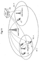
- Fig. 1 is a block diagram showing an example of a radio communications system according to the first exemplary embodiment of the present invention.
- This radio communications system includes a base station 1 (a first base station), a base station 2 (a second base station), a mobile station 100, a mobile station 101 and a Radio Network Controller 200 (hereinafter, referred to as "RNC").
- the base station 1 transmits the pilot signal to the mobile station in a cell 11.
- the mobile station 100 and the mobile station 101 which received the pilot signal form a radio link 1100 and a radio link 1101 respectively and communicate with the base station 1.
- the base station 2 can transmit the pilot signal to the mobile station in a cell 12.
- the mobile station 100 which received the pilot signal can form a radio link 1200 and communicate with the base station 2.
- the RNC 200 is connected with the base station 1 through a line 2001 and is also connected with the base station 2 through a line 2002.
- the RNC 200 manages the base station 1 and the base station 2.
- the line 2001 and the line 2002 may be either a cable line or a wireless line, and is described as the cable line in the following description.
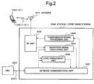
- Fig. 2 is a block diagram showing an example of the base station 1 as the first base station shown in Fig. 1 .
- the base station 1 includes a network communication unit 300, a RF (Radio Frequency) unit 302, a reception signal processing unit 304, a transmission signal processing unit 306, a load management unit 308 and an antenna 310.
- the network communication unit 300 performs cable communication with the RNC 200.
- the RF unit 302 performs radio communication with the mobile station 100.
- the reception signal processing unit 304 processes a signal received from the mobile station 100 via the RF unit 302.
- the transmission signal processing unit 306 processes a signal for transmitting to the mobile station 100 and transmits the signal to the RF unit 302.
- the load management unit 308 acquires communication traffic of the mobile station 100 which the base station 1 supports and number of the mobile stations 100 in the cell 11 from the reception signal processing unit 304 and the network communication unit 350 as load data.
- Fig. 3 is a block diagram showing an example of the base station 2 as the second base station shown in Fig. 1 .
- the base station 2 includes a network communication unit 350, a RF unit 352, a reception signal processing unit 354, a transmission signal processing unit 356, a state change control unit 358, a power control unit 360, an antenna 362 and a load management unit 364.
- the network communication unit 350 performs cable communication with the RNC 200.
- the RF unit 352 performs radio communication with the mobile station 100.
- the reception signal processing unit 354 processes a signal received from the mobile station 100 via the RF unit 352.
- the transmission signal processing unit 356 processes a signal for transmitting to the mobile station 100 and transmits the signal to the RF unit 352.
- the load management unit 364 acquires communication traffic of a mobile station which the base station 2 supports and number of the mobile stations in the cell 12 from the reception signal processing unit 356 and the network communication unit 350 as load data, and determines a presence of load in the base station 2. Also, the load management unit 364 inquires of the RNC 200 via the network communication unit 350 a received power status (whether the received power concerned exceeds a threshold value) of a pilot signal of the base station 2 in a mobile station (for example, mobile station 101 in Fig. 1 ) which exists around cell 12.
- the state change control unit 358 controls a change of operation states of the base station 2 according to the instructions or the information from the network communication unit 350, the reception signal processing unit 354 or the load management unit 364.
- the power control unit 360 executes electrical power control (for example, control of power ON/OFF) of the transmission signal processing unit 356, according to the instructions from the state change control unit 358. Besides, the power control unit 360 executes transmission power control and electrical power control (for example, control of power ON/OFF) of the RF unit 352, according to the instructions from the state change control unit 358.
- Fig. 4 is an explanatory drawing about state change of the base station 2 as the second base station.
- the base station 2 has two operation states as shown in Fig. 4 .
- the first operation state is an active state St_11 in which the base station 2 can form the radio link 1200 with the mobile station 100 which resides in the cell 12.
- the second operation state is a radio transmission suspension state St_12. In the radio transmission suspension state St_12, radio signal transmitted from the base station 2 to the mobile station 100 is suspended and radio communication between the base station 2 and the mobile station 100 in the cell 12 becomes impossible.
- the base station 2 executes the change from a certain operation state to another operation state whenever conditions like Fig. 4 are satisfied.
- a condition on which the base station 2 changes from the active state St_11 to the radio transmission suspension state St_12 is, for example, a condition that communication of the mobile station 100 in the base station 2 is disconnected and a mobile station which connects with the base station 2 does not exist any more.
- a start request that is, request for change from the radio transmission suspension state St_12 to the active state St_11
- the operation state of the base station 2 changes from the radio transmission suspension state St_12 to the active state St_11.
- the "radio transmission suspension state” means, specifically, for example, a state in which electrical power or transmission function of the transmission signal processing unit 356 or the RF unit 352 are turned off by the power control unit 360, and transmission from the base station 2 to the mobile station 100 is suspended.
- Fig. 5 is a sequence chart showing an example of operation of the radio communications system, when the base station 2 changes from the active state St_11 to the radio transmission suspension state St_12.
- Fig.5 explains operation sequence among the mobile station 100, the base station 2 and the RNC 200.
- the base station 2 is in communication with the mobile station 100 in the cell 12 (Step S1).
- a mobile station measures received power in the mobile station of the pilot signal of the base station (for example, the base station 1 and the base station 2 in Fig. 1 ) which is registered within a measurement cell set which is information reported from the base station in communication, and report the measurement result concerned to the RNC 200 periodically via the base station in communication.
- the measurement cell set is a set which includes cells (base stations) which become a target for which the mobile station measures received power of the pilot signal transmitted from the base station.
- the measurement cell set is prepared for in each base station.
- the measurement cell set is reported to the mobile station under the communication. In general, own base station and the base stations around it are registered in the measurement cell set.
- the mobile station 100 carries out communication disconnect processing to the base station 2 (Step S2).
- the base station 2 which received the communication disconnect request from the mobile station 100 confirms whether a mobile station in communication exists other than the mobile station 100 in the cell 12 of own base station (Step S3).
- the base station 2 transmits a received power status confirmation request to the RNC 200 (Step S4).
- the received power status confirmation request issued from the base station 2 is described.
- the RNC 200 has a result which compared received power information of the pilot signal of the base station 2 in a mobile station (for example, the mobile station 101 in communication with the base station 1 in Fig. 1 ) in communication with other base station in the neighborhood of the cell 12 with a predetermined threshold value.
- the received power status confirmation request means processing in which the base station 2 requests this comparison result to the RNC 200.
- the RNC 200 which received the request concerned compares a measurement result of a mobile station (here, the mobile station 101) which received the pilot signal of the base station 2 and performed measurement with the threshold value (Step S5). Next, the RNC 200 transmits the comparison result (received power status in the mobile station) to the base station 2 (Step S6).
- the base station 2 lowers transmission power of a transmission signal including the pilot signal gradually (for example, 1 dB per 0.1 second) (Step S7). Further, while the base station 2 is performing lowering processing of transmission power, the RNC 200 keeps comparing the measurement result of the received power of the pilot signal in the mobile station with the threshold value and keeps transmitting the comparison result to the base station 2. However, when a state change report of Step S11 described below is received, transmission of the comparison result is suspended. Next, while the base station 2 is lowering transmission power, whether a connection request from a new mobile station exists is confirmed (Step S8).
- Step S9 whether the received power in the mobile station transmitted from the RNC 200 does not exceed the threshold value is confirmed.
- the base station 2 performs processing from Step S5 to Step S9 repeatedly until transmission power goes down for fixed quantity (20 dB, for example) (that is, until transmission power becomes 1/100 of power in the active state St_11).
- Step S10 In case transmission power of the base station 2 goes below the predetermined threshold value (Step S10), the base station 2 notifies the RNC 200 of change to the radio transmission suspension state St_12 (Step S11). And the base station 2 which transmitted a state change report suspends radio transmission to the mobile station and changes to the radio transmission suspension state St_12 (Step S12).
- the RNC 200 which received the report concerned transmits a notification to the effect that the change report of the base station 2 was received by the RNC 200 to the base station 2 (Step S13). Also, together with transmitting the reception notification concerned, the RNC 200 directs the base station 1 to delete the base station 2 from the measurement cell set (Step 14). And the base station 1 which received the direction concerned updates the measurement cell set of the base station 1 and deletes the base station 2 (Step S15).
- the first condition (1) is, when communication of the mobile station 100 in communication in the cell 12 ended (in other words, in case a mobile station which communicates with the base station 2 does not exist any more).
- the second condition (2) is, when received power of the pilot signal of the base station 2 in the mobile station 100 which is in communication with other base station goes below a threshold value and fixed time has passed.
- the third condition (3) is, when starting of communication after change from the radio transmission suspension state St_12 to the active state St_11 cannot be performed, which is described below.
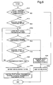
- the load management unit 364 of the base station 2 judges, as load data of the base station 2, a presence of a mobile station in communication (whether number of a mobile station is 0, or whether communication traffic is 0) (Step S20). In case a mobile station in communication with the base station 2 is judged "to exist" (in case judged as No in Step S20), the load management unit 364 issues a direction to the state change control unit 358 to keep an operation state of the base station 2 in the active state St_11 (Step S29). As a result, the state change control unit 358 directs the power control unit 360 to keep transmission power in a usual operation state, and as a result, the active state which is a usual communication state is kept.
- the load management unit 364 inquires of the RNC 200 via the network communication unit 350 a received power status (whether the received power concerned exceeds a threshold value) of the pilot signal of the base station 2 in a mobile station (the mobile station 101 in Fig. 1 , for example) which exists around the cell 12 (Step S21).
- the received power concerned exceeds the threshold value (in case judged as Yes in Step S21)
- the network communication unit 350 receives from the RNC 200 a notice to the effect that received power of the pilot signal of the base station 2 in the mobile station exceeds the threshold value, it outputs the notification to the state change control unit 358.
- the state change control unit 358 issues a direction to keep an operation state of base station 2 in the active state St_11 (Step S29).
- the network communication unit 350 receives from the RNC 200 a notice to the effect that received power of the pilot signal of the base station 2 in the mobile station does not exceed the threshold value, it outputs the notification to the state change control unit 358.
- the state change control unit 358 issues a direction to the power control unit 360 to lower gradually transmission power of a control signal including the pilot signal.
- the power control unit 360 which received the direction to lower transmission power outputs a direction to lower gradually transmission power of the transmission signal processing unit 356 (Step S22).
- the transmission signal processing unit 356 is lowering transmission power by control of the power control unit 360, the base station 2 carries out processing described in Step S23 and Step S24 repeatedly.
- the reception signal processing unit 354 confirms whether a new connection request from the mobile station in the cell 12 of own base station exists (Step S23).
- the network communication unit 350 receives from the RNC 200 periodically received power status of the base station 2 in the mobile station, and confirms it (Step S24). In case a new connection request exists from the mobile station in the cell 12 while lowering transmission power (in case judged as Yes in Step S23) or a notification is received from the RNC 200 to the effect that received power of the pilot signal of the base station 2 in the mobile station which is in communication with other base station (the mobile station 101 in Fig.
- Step S24 At least one of the reception signal processing unit 354 and the network communication unit 350 outputs to the state change control unit 358 control information or a direction to make transmission power rise to a prescribed value.
- the state change control unit 358 issues a direction to the power control unit 360 to make transmission power of a control signal including the pilot signal in the transmission signal processing unit 356 rise to a prescribed value.
- the power control unit 360 controls the transmission signal processing unit 356, makes transmission power rise (Step S28), and keeps an operation state of the base station 2 in the active state St_11 (Step S29).
- the transmission signal processing unit 356 judges whether transmission power is lowered to a predetermined threshold value (Step S25).
- the transmission signal processing unit 356 notifies the state change control unit 358 and further, the state change control unit 358 reports to the RNC 200 via the network communication unit 350 to the effect that the base station 2 changes to the radio transmission suspension state St_12 (Step S26).
- the state change control unit 358 issues a direction to the power control unit 360 to suspend transmission of the pilot signal of the transmission signal processing unit 356 (Step S27). As a result, an operation state of the base station 2 becomes the radio transmission suspension state St_12.
- transmission power lowering processing of the base station 2 is not limited to the above.
- the power control unit 360 or the transmission signal processing unit 356 of the base station 2 can lower transmission power to a predetermined value not gradually but quickly.
- at least processing of Step S23, and depending on the case, processing of Step S24 in Fig. 6 can also be omitted.
- "predetermined value" mentioned above includes a state when a signal is not outputted at all, that is, power "0" ("0" watt, for example).
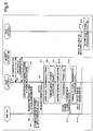
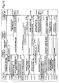
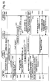
- Fig. 7 is a sequence chart showing an example of operation of the radio communications system in the first exemplary embodiment on the occasion when the second base station changes from a radio transmission suspension state to an active state and hands over a mobile station which are accommodated in the first base station to the second base station.
- the mobile station 100 is supposed to communicate first with the base station 1 newly.
- the mobile station 100 transmits a connection request concerning an outgoing call and so on to the base station 1 in the neighborhood of the base station 2 (Step S30).
- the base station 1 which received the connection request of the mobile station 100 notifies the RNC 200 that the mobile station 100 issued the connection request (Step S31).
- the base station 1 measures load based on traffic amount and so on of own base station (Step S32).
- the base station 1 transmits measured load data to the RNC 200 (Step S33).
- the RNC 200 compares the load data of the base station 1 with a predetermined threshold value (Step S34).
- the RNC 200 transmits a start request to the base station 2 (Step S35).
- the base station 2 which received the start request from the RNC 200 makes an operation state change from the radio transmission suspension state St_12 to the active state St_11 (Step S36).
- the base station 2 which changed to the active state St_11 starts transmission of a control signal including the pilot signal with prescribed transmission power (Step S37).
- the base station 2 which started transmission of the pilot signal reports (start report) to the RNC 200 that it changed to active (Step S38).
- the RNC 200 which received the start report from the base station 2 issues a connection permission notification to the base station 1 to the effect that the base station 1 and the mobile station 100 are permitted to connect (Step S39).
- the base station 1 which received the connection permission notification from the RNC 200 issues the connection permission notification to the mobile station 100 (Step S40).
- the mobile station 100 which obtained the connection permission from the base station 1 starts communication of user data (main information of communication (sound or data, for example)) with the base station 1 (Step S41).
- the RNC 200 directs to add the cell 12 of the base station 2 to the measurement cell set of the base station 1 concurrently with Step S39 (Step S42).
- the base station 1 which received from the RNC 200 the addition direction to the measurement cell set adds the base station 2 to the measurement cell set (Step S43) and notifies the mobile station which is in communication of update of the measurement cell set (Step S44).
- the mobile station 100 which received from the base station 1 the update notification of the measurement cell set measures received power of the pilot signal which is transmitted from the base stations (the base station 1 and the base station 2 in Fig. 1 , for example) registered within the new measurement cell set (Step S45). And the measurement result is transmitted to the base station 1 (Step S46).
- the base station 1 transmits the measurement result received from the mobile station 100 to the RNC 200 (Step S47).
- the RNC 200 which received the measurement result compares received power of the base station 2 in the mobile station 100 with a threshold value (Step S48).
- the RNC 200 notifies the base station 1 and the base station 2 respectively, of a command to the effect that the mobile station 100 is handed over from the base station 1 to the base station 2 (Step S49 and Step S50).
- the base station 1 which received the handover command concerned from the RNC 200 issues to the mobile station 100 a command to the effect that communication is handed over to the base station 2 (Step S51).
- the base station 2 hands over communication of the mobile station 100 from the base station 1, and starts user data communication with the mobile station 100 (Step S52).
- the base station 2 reports to the RNC 200 to the effect that a connection is established with the mobile station 100 (Step S53).
- the RNC 200 notifies the base station 2 to the effect that the connection establishment is confirmed (Step S54).
- the RNC 200 commands the base station 1 to disconnect communication with the mobile station 100 (Step S55).
- the base station 1 which received the communication disconnect command disconnects communication with the mobile station 100 (Step S56).
- handover processing of the mobile station 100 from the base station 1 to the base station 2 ends.
- Step S48 in case received power of the base station 2 is lower than the threshold value, the RNC 200 commands the base station 2 to call a flow (shown in Fig. 6 ) which changes to the radio transmission suspension state St_12.
- the base station 2 which received the command concerned operates based on the calling condition (3) of a flow to change from the active state St_11 to the radio transmission suspension state St_12 mentioned above.
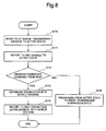
- Fig. 8 is a flow chart showing an example of operation of the second base station in the first exemplary embodiment on the occasion when the second base station changes from a radio transmission suspension state to an active state and hands over a mobile station which are accommodated the first base station to the second base station.
- the base station 2 in the radio transmission suspension state St_12 starts change from the radio transmission suspension state St_12 to the active state St_11 by receiving a start request from the RNC 200 after the mobile station 100 transmitted a connection request to the base station 1.
- the network communication unit 350 of the base station 2 which received the start request from the RNC 200 outputs the start request to the state change control unit 358.
- the state change control unit 358 issues a direction to make an operation state of the base station 2 change from the radio transmission suspension state St_12 to the active state St_11.
- the power control unit 360 issues a direction to make transmission power of a control signal including the pilot signal in the transmission signal processing unit 356 increase to a prescribed value.
- transmission of the pilot signal from the base station 2 starts (Step S70).
- the transmission signal processing unit 356 of the base station 2 reports (start report) to the RNC 200 via the network communication unit 300 that it changed to the active state (Step 71).
- the transmission signal processing unit 356 of the base station 2 confirms with the network communication unit 350 whether a handover command is received from the RNC 200 (Step S72).
- the transmission signal processing unit 356 and the reception signal processing unit 354 establish a connection with the mobile station 100 and start user data communication (Step S73).
- the transmission signal processing unit 356 reports to the RNC 200 via the network communication unit 350 to the effect that the connection between the base station 2 and the mobile station 100 is established (Step S74).
- processing shown in this flow that is, processing to make change from the radio transmission suspension state St_12 to the active state St_11, and to handover a mobile station which the base station 1 accommodates to the base station 2 ends.
- the state change control unit of the base station 2 judges that the base station 2 and the mobile station 100 cannot communicate or enough quality cannot be secured even if they can communicate. Accordingly, because the meaning is lost to keep the active state St_11 concerning communication with this mobile station 100, the base station 2 carries out processing to return the operation state of the base station 2 from the active state St_11 to the radio transmission suspension state St_12 (Step S75). Because this change processing is already described using Fig. 6 , its description will be omitted.
- the base station 2 is characterized by, in the radio transmission suspension state, when communication between the base station 1 and the mobile station 100 is started (specifically, when the mobile station 100 performs a connection request to the base station 1) and a predetermined condition is satisfied, starting transmission of the pilot signal with predetermined power.
- the base station 2 as the second base station starts transmission of the pilot signal to the mobile station 100 (that is, it changes from the radio transmission suspension state St_12 to the active state St_11).
- the base station 2 includes: a means (the network communication unit 350, for example) which receives a start request transmitted from other equipment when communication between the base station 1 and the mobile station 100 is started and a predetermined condition is satisfied, and a means (the state change control unit 358 and the power control unit 360, for example) which starts transmission of the pilot signal with predetermined power based on the start request.
- a means the network communication unit 350, for example
- the state change control unit 358 and the power control unit 360 for example
- own base station can be set to the active state St_11. Accordingly, for example, returning to an active state wastefully like Japanese Patent Application Laid-Open No. 2003-37555 is avoided, and as a result, it becomes possible, with more certainty, to suppress consumption of electric power of the base station and avoid radio interference between the base stations.
- the base station 2 of the radio communications system judges, in case there are no handover commands from the RNC 200 after changing to the active state St_11, that a mobile station which communicates with the base station 2 does not exist, the base station 2 and the mobile station 100 cannot communicate, or enough quality cannot be secured even if they can communicate. And in that case, the base station 2 judges that the meaning to keep the active state St_11 concerning communication with this mobile station 100 is lost and carries out processing to return the operation state of the base station 2 from the active state St_11 to the radio transmission suspension state St_12.
- the base station 2 includes a means to suspend transmission of the pilot signal (the state change control unit 358 and the power control unit 360, for example) after it has started transmission of the pilot signal, in case a mobile station which communicates with the base station 2 does not exist, the base station 2 and a mobile station cannot communicate, or enough quality cannot be secured even if they can communicate.
- the pilot signal the state change control unit 358 and the power control unit 360, for example
- a case for one second base station (that is, a base station which changes between the radio transmission suspension state St_12 and the active state St_11 appropriately, specifically the base station 2 in Fig. 1 ) is given as an example.
- number of second base stations may be plural.
- all second base stations return to the active state St_11 and those other than the base station which is in communication with a mobile station keep the active state wastefully.
- the load data is not limited to communication traffic.
- the load data can, for example, be made as "number of mobile stations in connection" of the base station 1. It is also possible to adopt both "communication traffic information" and "information of number of mobile stations in connection” as load data.
- sequence of processing in which the mobile station 100 which obtained connection permission from the base station 1 (the first base station) starts communication of user data with the base station 1 is not limited to the sequence shown in Fig. 7 .
- the user data communication start processing concerned may be performed before processing in which the base station 2 (the second base station) changes to the active state St_11 (Step S36) or may be performed after processing in which the base station 1 adds the base station 2 to the measurement cell set (Step S43).
- Step S32 a case to perform starting of the user data communication concerned before load measurement of the base station 1 (Step S32) is performed can be given as an example.
- the base station 1 can perform more correct load measurement.
- starting of the user data communication concerned may be performed after processing to transmit a start request from the RNC 200 to the base station 2 (Step S35). As a result, it becomes possible to reduce connection delay.
- a case to perform it after update notification processing (Step S44) of the measurement cell set from the base station 1 to the mobile station (for example, the mobile station 101 in Fig. 1 ) in communication with the base station 1 concerned can be given as an example.
- a radio communications system according to the second exemplary embodiment of the present invention is described.
- the entire structure of this radio communications system is identical with the radio communications system of the first exemplary embodiment shown in Fig. 1 .
- the base station 1 as the first base station is replaced by the base station 4 described below.
- the difference of the second exemplary embodiment from the first exemplary embodiment exists in a structure of the first base station.
- a base station as the first base station in the radio communications system of the second exemplary embodiment is newly referred to as a base station 4.
- a base station corresponding to the second base station in this radio communications system remains as the base station 2 of the first exemplary embodiment (refer to Fig. 3 ).
- Fig. 9 is a block diagram showing an example of the base station 4 as the first base station of the second exemplary embodiment.
- the base station 4 further includes a location information acquisition unit 450 in addition to a structure included in the base station 1 as the first base station in the first exemplary embodiment shown in Fig. 2 . Because a structure and an operation of other components (that is, a network communication unit 300, a RF unit 302, a reception signal processing unit 304, a transmission signal processing unit 306, a load management unit 308 and an antenna 310) are the same as the base station 1, their description will be omitted.
- the location information acquisition unit 450 acquires or detects location of a mobile station residing in the cell 11 of the base station 4 based on information obtained from the reception signal processing unit 304.
- operation sequence of the radio communications system in case the second base station changes from the active state to the radio transmission suspension state is the same as operation sequence of the radio communications system in the first exemplary embodiment (refer to Fig. 5 ).
- an operation flow of the second base station in case of change from the active state to the radio transmission suspension state is the same as the operation flow of the second base station (refer to Fig. 6 ). Accordingly, hereinafter, description about the operation sequence mentioned above and the operation flow mentioned above will be omitted.
- Fig. 10 is a sequence chart showing an example of operation of the radio communications system in the second exemplary embodiment on the occasion when the second base station changes from a radio transmission suspension state to an active state and hands over a mobile station which are accommodated in the first base station to the second base station.
- load data between the mobile station 100 and the base station 4 and location information of the mobile station are used as a condition to change state of the base station 2 from the radio transmission suspension state St_12 to the active state St_11.
- the mobile station 100 transmits a connection request to the base station 4 (though described as the base station 1 in Fig. 1 , hereinafter, considered as the base station 4 as mentioned above) in the neighborhood of the base station 2 (Step S149).
- the base station 4 which received the connection request of the mobile station 100 notifies the RNC 200 that the mobile station 100 issued the connection request (Step S150).
- the base station 4 measures load data of own base station (Step S151).
- the base station 1 transmits measured load data to the RNC 200 (Step S152).
- the RNC 200 compares the load data of the base station 4 with a predetermined threshold value (Step S153).
- the base station 4 requests location information of the mobile station 100 to the mobile station 100 (Step S154).
- the mobile station 100 which received the location information request from the base station 4 acquires location information using a location information acquisition means (GPS (Global Positioning System), for example) (Step S155).
- the mobile station 100 which acquired the location information transmits the location information to the base station 4 (Step S156).
- the base station 4 which acquired the location information of the mobile station transmits the location information of the mobile station 100 to the RNC 200 (Step S157).
- Step S153 processing in case load data of the base station 4 is judged in Step S153 to be higher than a threshold value is described.
- the RNC 200 compares, using location information of the mobile station 100, location relationship between the mobile station 100 and an area possible to communicate with the base station 2 (the cell 12 in Fig. 1 ) which is at present in the radio transmission suspension state St_12 and, when it becomes the active state St_11, is to be registered within the measurement cell set of the base station 4 (Step S158).
- the RNC 200 determines this base station 2 as a base station to start (Step S159). Accordingly, the RNC 200 transmits a start request to the base station 2 (Step S160).
- the base station 2 which received the start request from the RNC 200 makes an operation state change from the radio transmission suspension state St_12 to the active state St_11 (Step S161).
- the base station 2 which changed to the active state St_11 starts transmission of a control signal including the pilot signal with prescribed power (Step S162).
- the base station 2 which changed to the active state reports (start report) to the RNC 200 that it changed to the active state (Step S163).
- the RNC 200 which received information to the effect that the base station 2 changed to the active state issues a connection permission notification to the base station 4 to the effect that the base station 4 and the mobile station 100 are permitted to connect (Step S164).
- the base station 4 which received the connection permission notification from the RNC 200 issues the connection permission notification to the mobile station 100 (Step S165).
- user data communication is started between the base station 4 and the mobile station 100 (Step S166).
- the RNC 200 After transmitting user data communication permission with the mobile station 100 to base station 4, the RNC 200 directs the base station 4 to add the cell 12 of the base station 2 to a measurement cell set of the base station 4 (Step S167).
- the base station 4 which received the direction adds the cell 12 to the measurement cell set (Step S168) and notifies the mobile station which is in communication of update of the measurement cell set (Step S169).
- the mobile station 100 which received the update notification of the measurement cell set from the base station 4 measures the pilot signal received power which is transmitted from the base stations (for example, the base station 4 and the base station 2 in Fig. 1 ) registered within the new measurement cell set (Step 170).
- the measurement result is transmitted to the base station 4 (Step S171).
- the base station 4 transmits the measurement result received from the mobile station 100 to the RNC 200 (Step S172).
- the RNC 200 which received the measurement result compares received power of the base station 2 in the mobile station 100 with the threshold value (Step S173).
- the RNC 200 In case the received power of the base station 2 is higher than the threshold value, the RNC 200 notifies the base station 4 and the base station 2 respectively, of a command to the effect that the mobile station 100 is handed over from the base station 4 to the base station 2 (Step S174 and Step S175).
- the base station 4 which received the handover command concerned from the RNC 200 issues to the mobile station 100 a command to the effect that communication is handed over to the base station 2 (Step S176).
- the base station 2 hands over communication of the mobile station 100 from the base station 4, and starts user data communication with the mobile station 100 (Step S177).
- the base station 2 reports on the RNC 200 about connection establishment with the mobile station 100 (Step S178).
- the RNC200 notifies the base station 2 a confirmation of connection establishment based on this report (step S179).
- the RNC 200 commands the base station 4 to disconnect communication with the mobile station 100 (Step S180).
- the base station 4 which received communication disconnect command disconnects communication with the mobile station 100 (Step S181).
- handover processing of the mobile station 100 from the base station 4 to the base station 2 ends.
- the second exemplary embodiment can, by using load data of the base station 4 and location information of the mobile station, select the base station to start (that is, to change from the radio transmission suspension state St_12 to the active state St_11) without waste and efficiently. That is, when load of the base station 4 as the first base station is light, the base station 2 as the second base station can keep the radio transmission suspension state St_12, and also by using location information of the mobile station, not only leveling of traffic between the base stations is achieved but also radio interference to other communication and wasteful power consumption are suppressed. In this case, a base station which accommodates a lot of mobile stations can be started by priority around the base station in the radio transmission suspension state regardless of order of a connection request or connection of a mobile station.
- the mobile station 100 resides in the cell 12 which is within a range possible to communicate with the base station 2. Accordingly, by starting the base station 2, the mobile station 100 can be accommodated by the base station 2. However, the mobile station 101 is located in a place where the base station 2 can not be used. Accordingly, even if the mobile station 101 enters newly cell 11 of the base station 4 and requests connection, and load of the base station 4 increases as a result, it is not possible to handover to the base station 2 and to accommodate the mobile station 101. That is, load of the base station 4 can not be reduced.
- This exemplary embodiment may resolve this problem as follows.
- the RNC 200 detects location of all mobile stations which are in connection with the base station 4 and searches out a mobile station that exists in the cell 12 of the base station 2 from among those mobile stations. In case no smaller than one mobile station which is in connection with the base station 4 and resides in the cell 12 exists, the RNC 200 starts the base station 2, and hands over at least one mobile station which is in connection with the base station 4 and resides in the cell 12 from the base station 4 to the base station 2. Thus, load of the base station 4 can be reduced.
- GPS Global Positioning System
- AGPS Assisted GPS
- AFLT Advanced Forward Link Trilateration
- a base station 2-1 and a base station 2-2 as the second base station are at present in the radio transmission suspension state St_12. And for example, suppose a case where three mobile stations 104-106 located in a cell 15 of the base station 2-1 issue a connection request to the base station 4 as the first base station and one mobile station 107 located in a cell 16 of the base station 2-2 issues a connection request to the base station 4.
- the RNC 200 detects location of all mobile stations which are in connection with the base station 4 and finds a mobile station among those mobile stations which resides in the cell 15 of the base station 2-1 and in the cell 16 of the base station 2-2. In this case, as mentioned above, three mobile stations 104-106 reside in the cell 15 of the base station 2-1, and one mobile station 107 resides in the cell 16 of the base station 2-2. In this case, it is possible for the RNC 200, for example, in selection of base station to start in Step S159 of Fig.
- sequence of processing in which the mobile station 100 which obtained connection permission from the base station 4 (first base station) starts communication of user data with the base station 4 is not limited to the sequence shown in Fig. 10 .
- the user data communication start processing concerned may be performed before processing in which the base station 2 (second base station) changes to the active state St_11 (Step S161) or may be performed after processing in which the base station 4 adds the base station 2 to the measurement cell set (Step S168).
- Step S151 a case to perform starting of the user data communication concerned before load measurement of the base station 4 (Step S151) is performed can be given as an example.
- the base station 4 can perform more correct load measurement.
- starting of the user data communication concerned may be performed after processing to transmit a start request from the RNC 200 to the base station 2 (Step S160). As a result, it becomes possible to reduce connection delay.
- a case to perform it after update notification processing (Step S169) of the measurement cell set from the base station 4 to a mobile station (for example, the mobile station 101 in Fig. 1 ) in communication with the base station 4 concerned can be given as an example.
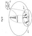
- Fig. 12 is a block diagram showing an example of a radio communications system according to the third exemplary embodiment of the present invention.
- the radio communications system installs the base station 2 as the second base station which performs a radio transmission suspension, in the cell 11 in which a base station 5 as the first base station can communicate, as an adjacent base station of the base station 5.
- a cell in which base station 2 can communicate is a cell 17. In this case, at least part of the cell 17 and the cell 11 overlap.
- the base station 5 as the first base station has the identical structure with the base station 4 of the second exemplary embodiment
- the base station 2 as the second base station has the identical structure with the base station 2 of the first and second exemplary embodiment. Accordingly, description will be made hereafter, for the base station 5, by using a configuration of the base station 4 of Fig. 9 , while for the base station 2, by using a configuration of the base station 2 shown in Fig. 3 .
- the RNC 200 includes a relation table (not shown) which relates unique ID of a mobile station and a start target base station.
- a relation table (not shown) which relates unique ID of a mobile station and a start target base station.
- the RNC 200 refers to the relation table and sets an adjacent base station (for example, the base station 2 in Fig. 12 ) related to the unique ID of the mobile station concerned as a base station of start target. And the mobile station concerned performs user data communication with the related adjacent base station.
- Fig. 13 is a sequence chart showing an example of operation of the radio communications system in the third exemplary embodiment on the occasion when the second base station changes from a radio transmission suspension state to an active state and hands over a mobile station which are accommodated in the first base station to the second base station.
- a mobile station 108 transmits a connection request to the base station 5 in the neighborhood of the base station 2 (Step S200).
- the base station 5 which received the connection request of the mobile station 108 notifies the RNC 200 that the mobile station 108 issued the connection request (Step S201).
- the RNC 200 receives the connection request of the mobile station 108 from the base station 5 and extracts unique ID of the mobile station 108 from the received connection request. By referring to a relation table and a table of all base stations registered within a measurement cell set of the base station 5, the RNC 200 confirms a presence of a base station which is related to the extracted unique ID and is in the radio transmission suspension state (Step S202).
- the base station 5 requests location information of the mobile station 108 to the mobile station 108 (Step S203).
- the mobile station 108 which received the request for location information acquires location information by using a location information acquisition means (Step S204).
- the mobile station 108 which acquired the location information transmits the location information to the base station 5 (Step S205).
- the base station 5 which acquired the location information of the mobile station 108 transmits the location information of the mobile station 108 to the RNC 200 (Step S206).
- Step S207 when a base station to which unique ID of the mobile station 108 is related exists in base stations registered within a measurement cell set of the base station 5 in Step S202, locations of the related base station and the mobile station are compared (Step S207). And the RNC 200 determines whether the base station is started based on unique ID of the mobile station and location information of the base station related to the ID (Step S208). Specifically, the RNC 200 judges whether the mobile station 108 resides in the cell 17 of a base station (in this case, the base station 2) which is related to unique ID of the mobile station 108 and is in a radio transmission suspension state by using location information of the mobile station 108.
- a base station in this case, the base station 2
- the RNC 200 determines to start the base station 2. Accordingly, the RNC 200 transmits a start request to the base station 2 (Step S209).
- the base station 2 which received the start request from the RNC 200 changes an operation state from the radio transmission suspension state St_12 to the active state St_11 (Step S210).
- the base station 2 which changed to the active state St_11 starts transmission of a control signal including the pilot signal according to prescribed transmission power (Step S211).
- the base station 2 which started transmission of the pilot signal reports (start report) to the RNC 200 that it changed to the active state (Step S212).
- the RNC 200 which received the start report from the base station 2 issues a connection permission notification which the base station 5 and the mobile station 108 are permitted to connect, to the base station 5 (Step S213).
- the base station 1 which received the connection permission notification from the RNC 200 issues connection permission to the mobile station 108 (Step S214).
- the mobile station 108 which obtained the connection permission from the base station 5 starts user data communication with the base station 5 (Step S215).
- the RNC 200 directs to add the cell 17 of the base station 2 to a measurement cell set of the base station 5 concurrently with Step S210 (Step S216).
- the base station 5 which received from the RNC 200 the addition direction to the measurement cell set adds the base station 2 to the measurement cell set (Step S217) and notifies the mobile station which is in communication of update of the measurement cell set (Step S218).
- the mobile station 108 which received the update notification of the measurement cell set from the base station 5 measures received power of the pilot signal which is transmitted from base stations (the base station 5 and the base station 2 in Fig. 12 , for example) registered within the new measurement cell set (Step S219). And the measurement result is transmitted to the base station 5 (Step S220).
- the base station 5 transmits the measurement result received from the mobile station 108 to the RNC 200 (Step S221).
- the RNC 200 which received the measurement result compares received power of the base station 2 in the mobile station 108 with a threshold value (Step S222).
- the RNC 200 In case the received power of the base station 2 is higher than the threshold value, the RNC 200 notifies the base station 5 and the base station 2 respectively, of a command to the effect that mobile station 108 is handed over from the base station 5 to the base station 2 (Step S223 and Step S224).
- the base station 5 which received the handover command concerned from the RNC 200 issues to the mobile station 108 a command to the effect that communication is handed over to the base station 2 (Step S225).
- the base station 2 hands over communication of mobile station 108 from base station 5, and starts user data communication with mobile station 108 (Step S226).
- the base station 2 reports on a notification that a communication is established between the mobile station 108 to the RNC200 (step S227).
- the RNC 200 sends a notification that the connection establishment is confirmed, to the base station 2 (Step S228). Further, the RNC 200 commands the base station 5 to disconnect communication with the mobile station 108 (Step S229). The base station 5 which received the communication disconnect command disconnects communication with the mobile station 108 (Step S230).
- the RNC 200 gives connection permission to the base station 5, and the mobile station 109 and the base station 5 start to communicate.
- the mobile station 109 which is not related to the base station 2 communicates with the base station 5 without communicating with the base station 2.
- the first base station may inquire location information to a mobile station, for example, after receiving a direction from the RNC 200. Also, in case location information can be acquired from a signal of a mobile station which performed a connection request, location information does not need to be inquired newly to the mobile station.
- sequence of acquiring load data and location information of the first base station is not limited to examples of Fig. 10 (the second exemplary embodiment) or Fig. 13 (the third exemplary embodiment), and it may be replaced.
- respective threshold values may be changed depending on load data and location information. For example, even in case load of the first base station is light, in case a mobile station exists in the neighborhood of the second base station (for example, in case of the second exemplary embodiment, the base station 2), the second base station may be started. On the other hand, even in case load of the first base station is heavy, in case the mobile station is within a communication range of the second base station, the second base station may be started.
- the base station related to the mobile station by providing the base station related to the mobile station, the base station which communicates only with the specific mobile station can be set. That is, an emergency call and so on can be connected with priority compared with other mobile stations.
- information used to relate the mobile station and the base station is not limited to unique ID of the mobile station necessarily.
- calling information kinds of outgoing calls, for example
- the outgoing call concerned can be connected with priority compared with other general outgoing calls or communication quality of the outgoing call concerned can be made of high quality compared with other general outgoing calls.
- the base station 2 related to unique ID of a mobile station is installed, in case another base station 2 which is not related to unique ID exists, it is possible to operate similar to the third exemplary embodiment mentioned above.
- sequence of processing in which the mobile station 108 which obtained connection permission from the base station 5 (first base station) starts communication of user data with the base station 5 is not limited to the sequence shown in Fig. 13 .
- the user data communication start processing concerned may be performed before processing in which the base station 2 (second base station) changes to the active state St_11 (Step S210) or may be performed after processing in which the base station 5 adds the base station 2 to the measurement cell set (Step S217).
- Step S202 a case to perform starting of the user data communication concerned before confirmation processing by the RNC 200 about a presence of a base station which is related to extracted unique ID and is in a radio transmission suspension state
- Step S209 starting of the user data communication concerned may be performed after processing which transmits a start request from the RNC 200 to the base station 2. In this case, it becomes possible to reduce connection delay.
- a case to perform it after update notification processing (Step S218) of the measurement cell set from the base station 5 to the mobile station (for example, the mobile station 109 in Fig. 12 ) in communication with the base station 5 concerned can be given as an example.
- the handover of the mobile station from the first base station to the second base station is performed after starting "user data" communication between the first base station and the mobile station.
- the handover mentioned above can also be performed at a communication stage of "control signal" in which user data is not communicated.
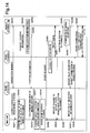
- Fig. 14 is a figure describing a first method for carrying out handover processing of a control signal at a communication stage, and a sequence chart showing an example of operation of a radio communications system on the occasion when the second base station changes from a radio transmission suspension state to an active state and hands over a mobile station which are accommodated in the first base station to the second base station in the third exemplary embodiment.
- Step S250 (the mobile station 108 transmits a connection request to the base station 5) ⁇ Step S262 (the base station 2 changes to the active state) are common with Steps S200 ⁇ S212 shown in Fig. 13 , their description will be omitted.
- the RNC 200 which received a start report from the base station 2 directs the mobile station 108 via the base station 5 to connect to the base station 2 (Step S263 and Step S264).
- the mobile station 108 which received the direction to connect to the base station 2 confirms whether the pilot signal of the base station 2 can be received (Step S265).
- the mobile station 108 which could confirm that the pilot signal could be received reports via the base station 5 that the pilot signal of the base station 2 could be received (Step S266 and Step S267).
- the RNC 200 which confirmed that the mobile station 108 could receive the pilot signal of the base station 2 transmits to the base station 2 permission to connect with the mobile station 108 (Step S268).
- the base station 2 which received the connection permission with the mobile station 108 transmits connection permission to the mobile station 108 (Step S269).
- the mobile station 108 which obtained the connection permission from the base station 5 starts user data communication with the base station 2 (Step S270).
- the mobile station 108 which received Step S264 may transmit a connection request to the base station 2 newly.
- the connection request which the mobile station 108 transmitted to the base station 5 is discarded after the RNC 200 transmits a connection base station direction.
- Fig. 15 is a figure describing a second method for carrying out handover processing of a control signal at a communication stage, and a sequence chart showing an example of operation of a radio communications system on the occasion when the second base station changes from a radio transmission suspension state to an active state and hands over a mobile station which are accommodated in the first base station to the second base station in the first exemplary embodiment.
- processing identical with processing shown in Fig. 7 is given a step number identical with Fig. 7 , and in the following description, a description of a step identical with Fig. 7 may be partly omitted.
- the mobile station 100 transmits a connection request (that is, "control signal") which concerns an outgoing call and so on to the base station 1 in the neighborhoods of the base station 2 (Step S30).
- the base station 1 notifies the RNC 200 that the mobile station 100 issued the connection request (Step S31).
- the base station 1 measures load based on traffic amount and so on of own base station (Step S32).
- the base station 1 transmits measured load data to the RNC 200 (Step S33).
- the RNC 200 compares the load data of the base station 1 with a predetermined threshold value (Step S34).
- the RNC 200 transmits a start request to the base station 2 (Step S35).
- the base station 2 makes an operation state change from the radio transmission suspension state St_12 to the active state St_11 (Step S36).
- the base station 2 which changed to the active state St_11 starts transmission of the control signal including the pilot signal with prescribed transmission power (Step S37).
- the base station 2 which started transmission of the pilot signal reports (start report) to the RNC 200 that it changed to active (Step S38). Processing of Steps S30-S38 described above is completely the same as Fig. 7 .
- processing required to start user data communication (that is, processing shown by Steps S39-S41 in Fig. 7 ) is omitted. That is, at this stage, only communication of the control signal alone is performed and communication of user data has not been started yet.
- the RNC 200 which received the start report from the base station 2 directs to add the cell 12 of the base station 2 to the measurement cell set of the base station 1 (Step S42).
- the base station 1 adds the base station 2 to the measurement cell set (Step S43) and notifies the mobile station 100 in communication (communication of a control signal only) of update of the measurement cell set (Step S44).
- the mobile station 100 measures received power of the pilot signal which is transmitted from the base stations (the base station 1 and the base station 2 in Fig. 1 , for example) registered within the new measurement cell set (Step 45). And the measurement result is transmitted to the base station 1 (Step S46).
- the base station 1 transmits the measurement result received from the mobile station 100 to the RNC 200 (Step S47).
- the RNC 200 which received the measurement result compares received power of the base station 2 in the mobile station 100 with a threshold value (Step S48).
- the RNC 200 determines a base station to connect based on the comparison result mentioned above (Step S500). For example, in case the received power of the pilot signal of the base station 2 is higher than the threshold value, the RNC 200 determines the base station 2 as a base station to connect. In this case, the RNC 200 notifies the base station 1 to which the mobile station 100 performed a connection request of a notification (hereinafter, referred to as a connection base station notification) which concerns this connection base station (Step S501), and the base station 1 notifies the mobile station 100 of this connection base station notification (Step S502).
- a connection base station notification which concerns this connection base station
- the RNC 200 notifies the base station 2 determined as the connection base station of connection permission with the mobile station (Step 503), and the base station 2 notifies the mobile station 100 of the connection permission (Step S504).
- the base station 2 starts user data communication with the mobile station 100 (Step S505).
- Fig. 16 is a figure describing a third method for carrying out handover processing of a control signal at a communication stage, and a sequence chart showing an example of operation of a radio communications system on the occasion when the second base station changes from a radio transmission suspension state to an active state and hands over a mobile station which are accommodated the first base station to the second base station in the first exemplary embodiment.
- processing identical with processing shown in Fig. 15 is given a step number identical with Fig. 15 , and in the following description, a description of a step identical with Fig. 15 may be partly omitted.
- Step S30 processing in which mobile station 100 transmits a connection request which concerns an outgoing call and so on (that is, "control signal") to the base station 1 in the neighborhood of the base station 2) to Step S43 (processing in which the base station 1 adds the base station 2 to the measurement cell set) is identical with the second method shown in Fig. 15 .
- the difference between the third method shown in Fig. 16 and the second method shown in Fig. 15 exists in a point that there are differences in the processing thereafter.
- the base station 1 resets a connection request (that is, connection request of Step S30 in Fig.
- Step S600 the mobile station 100 which received a reset command of the connection request performs a reception measurement of the pilot signal of each of the base station 1 and the base station 2 (Step S601).
- the mobile station 100 determines a base station to which transmits a connection request from the reception measurement result of the pilot signal (Step S602). For example, in case the received power of the pilot signal of the base station 2 is higher than a threshold value, the mobile station 100 determines the base station 2 as the base station to which transmits the connection request.
- the mobile station 100 transmits the connection request to the base station 2 (Step S603).
- the base station 2 transmits the connection request from the mobile station 100 to the RNC 200 (Step S604).
- the RNC 200 notifies the base station 2 of connection permission with the mobile station 100 (Step S605).
- the base station 2 notifies the mobile station 100 of the connection permission (Step S606).
- the base station 2 starts user data communication with the mobile station 100 (Step S607).
- the RNC 200 does not need to request a received power report (result report of power measurement using the measurement cell set) of the base stations 1 and 2 to the mobile station 100. And this can be realized in such a way as, after the base station 1 receives a direction (Step S42) from the RNC 200 to the effect that it adds the base station 2 to the measurement cell set of the base station 1, and adds the base station 2 to the measurement cell set (Step S43), to re-perform acquisition of the pilot signal (Step S45) for the second time to the mobile station 100, and to perform a connection request once again to a base station with high received power.
- each of the first to third methods for carrying out handover processing of a control signal at a communication stage described above can be applied to all of the first to third exemplary embodiments.
- a part which adds a cell of a base station which became the active state to the measurement cell set and gives a direction to a mobile station to measure the cell may be omitted;
- a mobile station may, by receiving the pilot signal autonomously, measuring its power, and receiving an identification signal of a cell from a control signal of the cell and so on, report the pilot received power together with an identification number of the cell.
- control to perform changes to the active state and the radio transmission suspension state may be performed by a cell unit.
- the RNC 200 is not necessarily an indispensable component.
- the first base station from which handover originates (for example, in case of the first exemplary embodiment, the base station 1) can be made to function as the RNC 200.
- the base station 1 and the base station 2 are connected directly, for example, via a cable communication network.
- the base station 2 as the second base station can receive, for example, "start request" (for example, in case of the first exemplary embodiment, Step S35 of Fig. 7 ) which is a direction for own base station to change to the active state St_11, directly from other equipment than the RNC 200, for example, from the base station 1 as the first base station.
- the first base station (for example, in case of the first exemplary embodiment, the base station 1) may include a function (for example, in case of the first exemplary embodiment, Step S5 in Fig. 5 ) in which the RNC 200 compares received power with a threshold value.
- the base station 1 may notify the base station 2 via the RNC 200 of received power status.
- a function to compare load data with a threshold value of Step S34 in Fig. 7 may be included in the base station 1.
- the base station 1 may request via the RNC 200 to start the base station 2.
- the RNC 200 compares a measurement result of the mobile station (for example, the mobile station 101 in Fig. 1 ) which received the pilot signal of the base station 2 and performed measurement with a threshold value (Step S5) and transmits the comparison result concerned to the base station 2 (Step S6).
- the comparison processing mentioned above can be performed by the base station 2, not by the RNC 200.
- the RNC 200 which received a received power status confirmation request from the base station 2 does not perform comparison processing and transmits the measurement result itself mentioned above (that is, received power information of the pilot signal of the base station 2 in a mobile station in communication with other base station in the neighborhood of the cell 12, for example, the mobile station 101 in communication with the base station 1 in Fig. 1 ) to the base station 2.
- the base station 2 compares the measurement result concerned with a predetermined threshold value.
- the predetermined threshold value may be stored in advance before the comparison processing concerned, for example, in a predetermined storage means of the base station 2. Also, the threshold value can be changed dynamically depending on a predetermined condition.
- the RNC 200 compares a measurement result of a mobile station (for example, mobile station 101 in Fig. 1 ) which received the pilot signal of the base station 2 and performed measurement with a threshold value (Step S5), transmits the comparison result concerned to the base station 2 (Step S6), and in case the measurement result mentioned above is below the threshold value, the base station 2 changes to the radio transmission suspension state St_12 (corresponds to processing of Steps S7-S12 of Fig. 5 ).
- a condition on which the second base station changes to the radio transmission suspension state St_12 is not limited to the above.
- the RNC 200 which received (Step S4 of Fig. 5 ) a received power status confirmation request from the base station 2 in case judged that a mobile station (a mobile station to which a control signal of a second base station is transmitted) in communication with the base station 1 does not exist, sets a comparison result to "measurement result is no more than a threshold value" forcibly and transmits it to the base station 2 (corresponds to Step S6 of Fig. 5 ).
- the base station 2 which received the comparison result concerned changes to the radio transmission suspension state St_12 by performing Steps S7-S12 of Fig. 5 .
- a mobile station which performed a connection request newly to the first base station is handed over from the first base station to the second base station
- a mobile station which was handed over to the cell 11 from a cell other than the cell 11 can be handed over from the first base station to the second base station.
- the threshold value may be changed depending on load data of the first base station. For example, by setting up the threshold value so that handover tends to take place easier when load is heavy, it becomes easier to get the effect of load balancing.
- processing of Step 5 shown in Fig. 5 may be performed in the second base station.
- the second base station 2 requesting received power information to the RNC 200
- the RNC 200 which received the request transmitting a measurement result of a mobile station to the second base station, and by the second base station comparing the transmitted measurement result of a mobile station with a threshold value
- similar operation can be possible.
- the RNC 200 may transmit from a result with high numerical value among measurement results in a mobile station. By transmitting from a high result, it becomes possible to complete comparison processing in the second base station (processing equivalent to step S5 which shifted to a second base station) quickly.
- Step S13 that is, processing in which the RNC 200 notifies the second base station of receiving state change information
- the RNC 200 it is possible for the RNC 200 to inquire load data of the first base station (the base station 1), and in order to restrict state change of the second base station (the base station 2) and keep the active state based on the load state concerned, to reply before Step S12.
- sequence of a start request for example, in case of the first exemplary embodiment, processing of Step S35 in Fig. 7 : transmission processing of a start request from the RNC 200 to the base station 2 and connection permission (for example, in case of the first exemplary embodiment, processing of Step S39 in Fig. 7 : transmission processing of a connection permission notification with the mobile station 100 from the RNC 200 to the base station 1)
- the RNC 200 issues to the base station 1 connection permission with a mobile station, and after the base station 1 and the mobile station 100 start to communicate, the base station 2 may change to the active state St_11.
- sequence of the connection permission and an addition direction of the measurement cell set (Step S42 in Fig. 7 : transmission processing of a direction to add the base station 2 to the measurement cell set of the base station 1) does not matter. That is, the direction to add the base station 2 to the measurement cell set may be before the base station 1 and the mobile station 100 start to communicate.
- Handover when a handover is performed, although only received power of the pilot signal of the base station 2 in a mobile station was used for decision criteria of handover (for example, in case of the first exemplary embodiment, Step S48 in Fig. 7 ), it is not limited to that. Handover may be carried out after comparison with received power of the pilot signal of the base station 1 in communication is performed. By comparing with the received power of the pilot signal of the base station 1, it becomes possible to prevent communication quality to degrade with handover.
- the first base station (the base station 1 and the base station 4) and the second base station (the base station 2) are loaded with exclusive functions respectively, and are special purpose machines conforming to each purpose.
- the function of the first base station and the second base station is to be shared. Accordingly, by so doing, it is possible for the second base station to carry a function of the first base station which was described above, and oppositely, for the first base station to carry a function of the second base station which was described above.
- the first base station and the second base station are controlled by special purpose hardware.
- a control program by a computer circuit (CPU (Central Processing Unit), for example) which is not shown, and operate.
- these control programs are stored in a storage medium (such as ROM (Read Only Memory) or hard disk, for example) inside each of base station mentioned above or in an external storage medium (such as removable media or removable disk, for example), and are read out by the computer circuit mentioned above and carried out.
- the second base station makes an operation state of own base station change to the active state St_11 (in other words, start transmission of the pilot signal with predetermined power) by a start request received from other equipment (for example, the RNC 200 or the first base station).
- the start request is a start request to the second base station based on a connection request by a mobile station to the first base station.
- the base station 2 can change to the active state St_11 autonomously not based on a direction from other equipment.
- the second base station receives a transmission signal from a mobile station to the first base station, and depending on a reception condition of the transmission signal concerned, can also recognize starting of communication between the first base station and the mobile station.
- the second base station can recognize starting of communication between the first base station and the mobile station by measuring a received power of the transmission signal of the mobile station in upstream band to the first base station.
- the second base station can recognize starting of communication between the first base station and a mobile station by detecting an outgoing call of the mobile station to the first base station.
- the second base station can recognize starting of communication between the first base station and a mobile station by judging, using radio resources allocation information which the first base station uses, whether a transmission signal of the mobile station to the first base station is included in a signal which the second base station received.
- radio resources allocation information is either of time slot information assigned to each mobile station, spreading code information assigned to each mobile station, or frequency band information assigned to each mobile station; or a combination of two or more of the information.
- the second base station is characterized by including a means which receives a transmission signal from a mobile station, and a means which, depending on a reception condition of the transmission signal concerned, starts transmission of the pilot signal with predetermined power when the predetermined condition is satisfied.
- a cell configuration of the first and the second base station of the radio communications system of the first to third exemplary embodiments described above can be made a hierarchy cell (also referred to as an overlap cell) structure.
- a hierarchy cell also referred to as an overlap cell
- the first base station a macro cell
- the second base station a small cell (micro cell, nano cell or femto cell, for example) whose entire cover area is included in the cover area of the macro cell.
- the soft handover is not indispensable.
- Form of handover which changes a base station of a connection destination of a mobile station does not matter.
- a method, where timing to change connection is estimated at base stations of a handover source and a handover destination, and handover is performed without waiting for a time to connect concurrently can be used.
Applications Claiming Priority (3)
| Application Number | Priority Date | Filing Date | Title |
|---|---|---|---|
| JP2008275915 | 2008-10-27 | ||
| PCT/JP2009/066569 WO2010050320A1 (fr) | 2008-10-27 | 2009-09-15 | Station de base, système de communication sans fil, procédé de commande de station de base, procédé de communication sans fil, et programme de commande de station de base |
| EP09823433.9A EP2341740B1 (fr) | 2008-10-27 | 2009-09-15 | Station de base, système de communication sans fil, procédé de commande de station de base, procédé de communication sans fil, et programme de commande de station de base |
Related Parent Applications (1)
| Application Number | Title | Priority Date | Filing Date |
|---|---|---|---|
| EP09823433.9A Division EP2341740B1 (fr) | 2008-10-27 | 2009-09-15 | Station de base, système de communication sans fil, procédé de commande de station de base, procédé de communication sans fil, et programme de commande de station de base |
Publications (1)
| Publication Number | Publication Date |
|---|---|
| EP3496473A1 true EP3496473A1 (fr) | 2019-06-12 |
Family
ID=42128688
Family Applications (2)
| Application Number | Title | Priority Date | Filing Date |
|---|---|---|---|
| EP18210697.1A Pending EP3496473A1 (fr) | 2008-10-27 | 2009-09-15 | Station de base, système de communication sans fil, procédé de commande de station de base, procédé de communication sans fil et programme de commande de station de base |
| EP09823433.9A Active EP2341740B1 (fr) | 2008-10-27 | 2009-09-15 | Station de base, système de communication sans fil, procédé de commande de station de base, procédé de communication sans fil, et programme de commande de station de base |
Family Applications After (1)
| Application Number | Title | Priority Date | Filing Date |
|---|---|---|---|
| EP09823433.9A Active EP2341740B1 (fr) | 2008-10-27 | 2009-09-15 | Station de base, système de communication sans fil, procédé de commande de station de base, procédé de communication sans fil, et programme de commande de station de base |
Country Status (7)
| Country | Link |
|---|---|
| US (7) | US8620374B2 (fr) |
| EP (2) | EP3496473A1 (fr) |
| JP (5) | JP5589847B2 (fr) |
| CN (2) | CN104469909B (fr) |
| ES (1) | ES2713298T3 (fr) |
| TR (1) | TR201901438T4 (fr) |
| WO (1) | WO2010050320A1 (fr) |
Families Citing this family (31)
| Publication number | Priority date | Publication date | Assignee | Title |
|---|---|---|---|---|
| EP3496473A1 (fr) | 2008-10-27 | 2019-06-12 | NEC Corporation | Station de base, système de communication sans fil, procédé de commande de station de base, procédé de communication sans fil et programme de commande de station de base |
| JP5293199B2 (ja) * | 2009-01-08 | 2013-09-18 | 富士通株式会社 | 無線通信装置、制御装置、移動通信システムおよび無線通信方法 |
| WO2011085546A1 (fr) * | 2010-01-13 | 2011-07-21 | 上海贝尔股份有限公司 | Procédé et dispositif de terminal d'utilisateur pour sélection de station de base d'accès |
| JP2012004999A (ja) * | 2010-06-18 | 2012-01-05 | Kyocera Corp | 無線通信システム、無線基地局、及び通信制御方法 |
| CN102083179B (zh) * | 2010-08-11 | 2014-04-02 | 电信科学技术研究院 | 一种节能小区的控制处理方法及基站 |
| EP2613587B1 (fr) * | 2010-09-01 | 2017-04-26 | Fujitsu Limited | Dispositif de commande, procédé de commande, et système de communications mobiles |
| JP5938896B2 (ja) * | 2011-02-14 | 2016-06-22 | ソニー株式会社 | 情報処理方法、情報処理装置および通信システム |
| EP2512171B1 (fr) * | 2011-04-14 | 2014-08-13 | Alcatel Lucent | Procédé de gestion de l'état de micro-stations de base en suivant les variations des exigences de trafic et dispositif contrôleur correspondant |
| EP2538713B1 (fr) * | 2011-06-24 | 2014-08-06 | Alcatel Lucent | Réalisation de mesures dans un réseau de télécommunication sans fil cellulaire numérique |
| KR20140046045A (ko) * | 2011-08-16 | 2014-04-17 | 후지쯔 가부시끼가이샤 | 전력 제어 방법, 기지국 및 단말 장비 |
| CN103209136A (zh) * | 2012-01-11 | 2013-07-17 | 中兴通讯股份有限公司 | 一种网络负荷控制方法及登记服务器 |
| JP5839109B2 (ja) | 2012-03-19 | 2016-01-06 | 富士通株式会社 | 移動通信システム及び電力制御方法及び小セルの基地局装置 |
| CN102800177B (zh) * | 2012-07-18 | 2016-04-06 | 宁波尚泰电子有限公司 | 用于报警器的无线互联通信模块的控制方法 |
| CN104584506B (zh) * | 2012-08-29 | 2018-04-27 | 索尼公司 | 通信装置、通信控制装置、程序和通信控制方法 |
| WO2014065273A1 (fr) * | 2012-10-22 | 2014-05-01 | 株式会社Nttドコモ | Système de communications, dispositif de communications mobiles, dispositif de commande de transition, procédé de commande de transition et programme de commande de transition |
| KR20140059598A (ko) * | 2012-11-08 | 2014-05-16 | 삼성전자주식회사 | 무선 통신 시스템에서 기지국 지원 탐색 방법 및 장치 |
| DE102013205486A1 (de) * | 2013-03-27 | 2014-10-02 | Deere & Company | Anordnung und Verfahren zur Positionserfassung mit einem Handgerät |
| EP3099134B1 (fr) * | 2014-02-18 | 2018-06-06 | Huawei Technologies Co., Ltd. | Système, dispositif et procédé d'accès |
| JP6298329B2 (ja) * | 2014-03-20 | 2018-03-20 | 株式会社Nttドコモ | ユーザ端末、無線基地局および無線通信方法 |
| EP3123806B1 (fr) * | 2014-03-26 | 2019-12-11 | Telefonaktiebolaget LM Ericsson (publ) | Configuration de connexion entre un terminal mobile et une station de base mobile sur la base d'une détection de mouvement conjoint |
| US10159037B2 (en) * | 2014-03-26 | 2018-12-18 | Telefonaktiebolaget Lm Ericsson (Publ) | Cell selection depending on relative speed between terminal and access point |
| WO2015163013A1 (fr) * | 2014-04-25 | 2015-10-29 | ソニー株式会社 | Dispositif de communication sans fil, procédé de communication sans fil, et système de communication sans fil |
| KR20160075995A (ko) * | 2014-12-19 | 2016-06-30 | 한국전자통신연구원 | 물리 채널 전송 방법 및 장치 |
| CA2976412A1 (fr) * | 2015-02-20 | 2016-08-25 | Nec Corporation | Systeme de communications sans fil, dispositif de station de base, dispositif de station mobile et procede de commande de communications sans fil |
| US9838290B2 (en) * | 2015-06-30 | 2017-12-05 | Ciena Corporation | Flexible ethernet operations, administration, and maintenance systems and methods |
| CN106714197B (zh) * | 2015-07-16 | 2020-01-31 | 普天信息技术有限公司 | 改善小区间干扰抖动的方法及系统 |
| US10085206B2 (en) * | 2016-03-08 | 2018-09-25 | Wipro Limited | Methods and systems for optimization of cell selection in TD-SCDMA networks |
| US11061999B2 (en) | 2018-11-06 | 2021-07-13 | Citrix Systems, Inc. | Systems and methods for dynamically enforcing digital rights management via embedded browser |
| JP7332380B2 (ja) * | 2019-07-29 | 2023-08-23 | 日本無線株式会社 | 移動型無線通信ユニット |
| CN116848936A (zh) * | 2021-02-22 | 2023-10-03 | 株式会社Ntt都科摩 | 通信装置和通信方法 |
| WO2024023931A1 (fr) * | 2022-07-26 | 2024-02-01 | 日本電信電話株式会社 | Système de communication sans fil, dispositif et procédé de commande, et programme associé |
Citations (5)
| Publication number | Priority date | Publication date | Assignee | Title |
|---|---|---|---|---|
| JPH10145842A (ja) * | 1996-11-08 | 1998-05-29 | Nec Corp | 無線基地局パワーセーブ移動通信システム |
| WO1998057516A2 (fr) * | 1997-05-28 | 1998-12-17 | Nokia Networks Oy | Commande d'unites emetteur-recepteur dans un systeme de radiocommunication cellulaire |
| WO2002007464A1 (fr) * | 2000-07-18 | 2002-01-24 | Telefonaktiebolaget Lm Ericsson (Publ) | Gestion de puissance adaptative d'un noeud d'un reseau cellulaire de telecommunications |
| JP2003037555A (ja) | 2001-07-23 | 2003-02-07 | Ntt Docomo Inc | 移動通信システムにおける無線基地局での送信電力制御方法及び移動通信システム並びに無線基地局 |
| JP2008275915A (ja) | 2007-04-27 | 2008-11-13 | Pioneer Electronic Corp | 駆動装置およびプラズマディスプレイ装置 |
Family Cites Families (30)
| Publication number | Priority date | Publication date | Assignee | Title |
|---|---|---|---|---|
| JPH031905A (ja) | 1989-05-31 | 1991-01-08 | Maeda Road Constr Co Ltd | 建築物、構築物用石材の加工方法 |
| JP2851494B2 (ja) * | 1992-08-05 | 1999-01-27 | 三菱電機株式会社 | 列車無線システム |
| JPH0847029A (ja) * | 1994-07-29 | 1996-02-16 | Hitachi Ltd | 移動通信システムおよびハンドオーバ方法 |
| GB2343330A (en) * | 1998-10-29 | 2000-05-03 | Fujitsu Ltd | Soft handoff method using a backup link |
| JP2002204478A (ja) * | 2000-12-28 | 2002-07-19 | Ntt Docomo Inc | 基地局制御装置、基地局制御方法及び移動通信システム |
| JP2003032264A (ja) | 2001-07-19 | 2003-01-31 | Fujitsu General Ltd | 無線lanシステム |
| JP2003174456A (ja) | 2001-12-06 | 2003-06-20 | Matsushita Electric Ind Co Ltd | 無線lanシステム |
| CN1324554C (zh) * | 2003-07-04 | 2007-07-04 | 财团法人工业技术研究院 | 单一型态晶体管扫描驱动电路 |
| JP2005354549A (ja) | 2004-06-14 | 2005-12-22 | Mitsubishi Electric Corp | 通信装置及び通信システム及び通信装置管理方法及びプログラム |
| CA2574052A1 (fr) * | 2004-07-16 | 2006-02-23 | Bridgeport Networks, Inc. | Detection de presence et transfert pour telephonie cellulaire et telephonie ip |
| EP3179775B1 (fr) * | 2004-07-30 | 2019-01-30 | Commscope Technologies LLC | Procédé et système de réglage des niveaux de puissance d'émetteur |
| JP2006217051A (ja) * | 2005-02-01 | 2006-08-17 | Hitachi Communication Technologies Ltd | 無線通信システム及び無線基地局制御装置 |
| EP2247136B1 (fr) | 2005-10-13 | 2016-04-27 | Mitsubishi Electric R&D Centre Europe B.V. | Détermination de la domaine d'operation d'une station de base dans un réseau cellulaire |
| CN101072391A (zh) * | 2006-05-08 | 2007-11-14 | 华为技术有限公司 | 无线演进网络中的基站及基站间交互负载信息的方法 |
| JP2008109423A (ja) * | 2006-10-26 | 2008-05-08 | Fujitsu Ltd | 無線基地局装置及びその省電力制御方法 |
| JP4916920B2 (ja) * | 2007-03-06 | 2012-04-18 | 三菱電機株式会社 | 移動体通信システム、隣接セルリスト管理方法および基地局 |
| CN102113384B (zh) * | 2008-07-30 | 2015-09-30 | 株式会社日立制作所 | 无线电通信系统和无线电通信方法 |
| US20100069073A1 (en) * | 2008-09-12 | 2010-03-18 | Industrial Technology Research Institute | System and method for system switch and handover between wireless communication systems |
| JP5365640B2 (ja) * | 2008-10-27 | 2013-12-11 | 日本電気株式会社 | 基地局、無線通信システム、基地局の制御方法、無線通信方法、および制御プログラム |
| EP3496473A1 (fr) * | 2008-10-27 | 2019-06-12 | NEC Corporation | Station de base, système de communication sans fil, procédé de commande de station de base, procédé de communication sans fil et programme de commande de station de base |
| US9144077B2 (en) * | 2009-09-17 | 2015-09-22 | Intel Mobile Communications GmbH | Radio resource manager devices and radio communication devices |
| US8902791B2 (en) * | 2010-10-01 | 2014-12-02 | Qualcomm Incorporated | Configuration control of inter-cell signaling based on power state |
| JP5938896B2 (ja) * | 2011-02-14 | 2016-06-22 | ソニー株式会社 | 情報処理方法、情報処理装置および通信システム |
| TW201330569A (zh) * | 2011-10-07 | 2013-07-16 | Interdigital Patent Holdings | 整合使用載波聚集不同無線電存取技術方法及裝置 |
| US20130250908A1 (en) * | 2012-03-23 | 2013-09-26 | Nokia Siemens Networks Oy | Base station power savings and control thereof |
| EP2883394A4 (fr) * | 2012-08-08 | 2016-07-13 | Nokia Solutions & Networks Oy | Procédés de réduction des interférences par activation de cellules dans des réseaux hétérogènes |
| US9445319B2 (en) * | 2013-02-14 | 2016-09-13 | Lg Electronics Inc. | Method and apparatus for controlling and resolving a handover failure when a dynamic cell off is occurred in wireless access system |
| WO2015046911A1 (fr) * | 2013-09-26 | 2015-04-02 | Lg Electronics Inc. | Procédé et appareil de signalisation entre des enb dans un système de communication sans fil prenant en charge la double connectivité |
| US9462117B2 (en) * | 2014-04-04 | 2016-10-04 | Apple Inc. | OAM system for LTE-U and Wi-Fi operation and coexistence deployment |
| US20160119969A1 (en) * | 2014-10-24 | 2016-04-28 | Qualcomm Incorporated | Mac enhancements for concurrent legacy and ecc operation |
-
2009
- 2009-09-15 EP EP18210697.1A patent/EP3496473A1/fr active Pending
- 2009-09-15 JP JP2010535732A patent/JP5589847B2/ja active Active
- 2009-09-15 CN CN201410681719.6A patent/CN104469909B/zh active Active
- 2009-09-15 TR TR2019/01438T patent/TR201901438T4/tr unknown
- 2009-09-15 US US13/126,325 patent/US8620374B2/en active Active
- 2009-09-15 CN CN200980142915.3A patent/CN102197690B/zh active Active
- 2009-09-15 WO PCT/JP2009/066569 patent/WO2010050320A1/fr active Application Filing
- 2009-09-15 EP EP09823433.9A patent/EP2341740B1/fr active Active
- 2009-09-15 ES ES09823433T patent/ES2713298T3/es active Active
-
2012
- 2012-10-26 US US13/661,896 patent/US8838126B2/en active Active
- 2012-10-26 US US13/661,874 patent/US8880085B2/en active Active
-
2014
- 2014-07-28 JP JP2014153111A patent/JP6068400B2/ja active Active
- 2014-08-22 US US14/465,896 patent/US9301166B2/en active Active
-
2016
- 2016-02-11 US US15/041,767 patent/US9693301B2/en active Active
- 2016-05-31 JP JP2016108599A patent/JP6274256B2/ja active Active
-
2017
- 2017-05-03 US US15/585,614 patent/US10123267B2/en active Active
- 2017-12-27 JP JP2017251551A patent/JP6421872B2/ja active Active
-
2018
- 2018-09-28 US US16/145,934 patent/US10499331B2/en active Active
- 2018-10-18 JP JP2018196301A patent/JP6787380B2/ja active Active
Patent Citations (5)
| Publication number | Priority date | Publication date | Assignee | Title |
|---|---|---|---|---|
| JPH10145842A (ja) * | 1996-11-08 | 1998-05-29 | Nec Corp | 無線基地局パワーセーブ移動通信システム |
| WO1998057516A2 (fr) * | 1997-05-28 | 1998-12-17 | Nokia Networks Oy | Commande d'unites emetteur-recepteur dans un systeme de radiocommunication cellulaire |
| WO2002007464A1 (fr) * | 2000-07-18 | 2002-01-24 | Telefonaktiebolaget Lm Ericsson (Publ) | Gestion de puissance adaptative d'un noeud d'un reseau cellulaire de telecommunications |
| JP2003037555A (ja) | 2001-07-23 | 2003-02-07 | Ntt Docomo Inc | 移動通信システムにおける無線基地局での送信電力制御方法及び移動通信システム並びに無線基地局 |
| JP2008275915A (ja) | 2007-04-27 | 2008-11-13 | Pioneer Electronic Corp | 駆動装置およびプラズマディスプレイ装置 |
Also Published As
Similar Documents
| Publication | Publication Date | Title |
|---|---|---|
| EP2341740B1 (fr) | Station de base, système de communication sans fil, procédé de commande de station de base, procédé de communication sans fil, et programme de commande de station de base | |
| US10219165B2 (en) | Radio communication system, radio communication method, radio base station and control station | |
| US9155099B2 (en) | Base station, radio communications system, control method of base station, radio communications method and control program | |
| CN107113639A (zh) | 用于在无线通信系统中控制接入点操作的方法 | |
| US8538431B2 (en) | Radio channel controller and radio channel controlling method | |
| US9094815B2 (en) | Base station in mobile communication system and wave stopping method | |
| JP2012105203A (ja) | 隣接セル処理装置、隣接セル処理方法およびデータ構造 | |
| KR20130056933A (ko) | 통신 시스템에서 기지국의 동작 제어 방법 및 장치 |
Legal Events
| Date | Code | Title | Description |
|---|---|---|---|
| PUAI | Public reference made under article 153(3) epc to a published international application that has entered the european phase |
Free format text: ORIGINAL CODE: 0009012 |
|
| STAA | Information on the status of an ep patent application or granted ep patent |
Free format text: STATUS: REQUEST FOR EXAMINATION WAS MADE |
|
| 17P | Request for examination filed |
Effective date: 20181206 |
|
| AC | Divisional application: reference to earlier application |
Ref document number: 2341740 Country of ref document: EP Kind code of ref document: P |
|
| AK | Designated contracting states |
Kind code of ref document: A1 Designated state(s): AT BE BG CH CY CZ DE DK EE ES FI FR GB GR HR HU IE IS IT LI LT LU LV MC MK MT NL NO PL PT RO SE SI SK SM TR |
|
| RBV | Designated contracting states (corrected) |
Designated state(s): AT BE BG CH CY CZ DE DK EE ES FI FR GB GR HR HU IE IS IT LI LT LU LV MC MK MT NL NO PL PT RO SE SI SK SM TR |