EP3491360B1 - Electron microscopy - Google Patents
Electron microscopy Download PDFInfo
- Publication number
- EP3491360B1 EP3491360B1 EP17745722.3A EP17745722A EP3491360B1 EP 3491360 B1 EP3491360 B1 EP 3491360B1 EP 17745722 A EP17745722 A EP 17745722A EP 3491360 B1 EP3491360 B1 EP 3491360B1
- Authority
- EP
- European Patent Office
- Prior art keywords
- sample
- fluid
- gas
- sample support
- support
- Prior art date
- Legal status (The legal status is an assumption and is not a legal conclusion. Google has not performed a legal analysis and makes no representation as to the accuracy of the status listed.)
- Active
Links
Images


Classifications
-
- G—PHYSICS
- G01—MEASURING; TESTING
- G01N—INVESTIGATING OR ANALYSING MATERIALS BY DETERMINING THEIR CHEMICAL OR PHYSICAL PROPERTIES
- G01N1/00—Sampling; Preparing specimens for investigation
- G01N1/28—Preparing specimens for investigation including physical details of (bio-)chemical methods covered elsewhere, e.g. G01N33/50, C12Q
- G01N1/30—Staining; Impregnating ; Fixation; Dehydration; Multistep processes for preparing samples of tissue, cell or nucleic acid material and the like for analysis
- G01N1/31—Apparatus therefor
- G01N1/312—Apparatus therefor for samples mounted on planar substrates
-
- B—PERFORMING OPERATIONS; TRANSPORTING
- B01—PHYSICAL OR CHEMICAL PROCESSES OR APPARATUS IN GENERAL
- B01L—CHEMICAL OR PHYSICAL LABORATORY APPARATUS FOR GENERAL USE
- B01L3/00—Containers or dishes for laboratory use, e.g. laboratory glassware; Droppers
- B01L3/50—Containers for the purpose of retaining a material to be analysed, e.g. test tubes
- B01L3/508—Rigid containers without fluid transport within
- B01L3/5085—Rigid containers without fluid transport within for multiple samples, e.g. microtitration plates
-
- B—PERFORMING OPERATIONS; TRANSPORTING
- B01—PHYSICAL OR CHEMICAL PROCESSES OR APPARATUS IN GENERAL
- B01L—CHEMICAL OR PHYSICAL LABORATORY APPARATUS FOR GENERAL USE
- B01L7/00—Heating or cooling apparatus; Heat insulating devices
- B01L7/50—Cryostats
-
- B—PERFORMING OPERATIONS; TRANSPORTING
- B01—PHYSICAL OR CHEMICAL PROCESSES OR APPARATUS IN GENERAL
- B01L—CHEMICAL OR PHYSICAL LABORATORY APPARATUS FOR GENERAL USE
- B01L9/00—Supporting devices; Holding devices
- B01L9/52—Supports specially adapted for flat sample carriers, e.g. for plates, slides, chips
- B01L9/523—Supports specially adapted for flat sample carriers, e.g. for plates, slides, chips for multisample carriers, e.g. used for microtitration plates
-
- G—PHYSICS
- G01—MEASURING; TESTING
- G01N—INVESTIGATING OR ANALYSING MATERIALS BY DETERMINING THEIR CHEMICAL OR PHYSICAL PROPERTIES
- G01N1/00—Sampling; Preparing specimens for investigation
- G01N1/28—Preparing specimens for investigation including physical details of (bio-)chemical methods covered elsewhere, e.g. G01N33/50, C12Q
- G01N1/2813—Producing thin layers of samples on a substrate, e.g. smearing, spinning-on
-
- G—PHYSICS
- G01—MEASURING; TESTING
- G01N—INVESTIGATING OR ANALYSING MATERIALS BY DETERMINING THEIR CHEMICAL OR PHYSICAL PROPERTIES
- G01N30/00—Investigating or analysing materials by separation into components using adsorption, absorption or similar phenomena or using ion-exchange, e.g. chromatography or field flow fractionation
- G01N30/02—Column chromatography
- G01N30/04—Preparation or injection of sample to be analysed
- G01N30/06—Preparation
- G01N30/12—Preparation by evaporation
-
- H—ELECTRICITY
- H01—ELECTRIC ELEMENTS
- H01J—ELECTRIC DISCHARGE TUBES OR DISCHARGE LAMPS
- H01J37/00—Discharge tubes with provision for introducing objects or material to be exposed to the discharge, e.g. for the purpose of examination or processing thereof
- H01J37/02—Details
- H01J37/023—Means for mechanically adjusting components not otherwise provided for
-
- H—ELECTRICITY
- H01—ELECTRIC ELEMENTS
- H01J—ELECTRIC DISCHARGE TUBES OR DISCHARGE LAMPS
- H01J37/00—Discharge tubes with provision for introducing objects or material to be exposed to the discharge, e.g. for the purpose of examination or processing thereof
- H01J37/02—Details
- H01J37/20—Means for supporting or positioning the object or the material; Means for adjusting diaphragms or lenses associated with the support
-
- B—PERFORMING OPERATIONS; TRANSPORTING
- B01—PHYSICAL OR CHEMICAL PROCESSES OR APPARATUS IN GENERAL
- B01L—CHEMICAL OR PHYSICAL LABORATORY APPARATUS FOR GENERAL USE
- B01L2300/00—Additional constructional details
- B01L2300/18—Means for temperature control
- B01L2300/1894—Cooling means; Cryo cooling
-
- H—ELECTRICITY
- H01—ELECTRIC ELEMENTS
- H01J—ELECTRIC DISCHARGE TUBES OR DISCHARGE LAMPS
- H01J2237/00—Discharge tubes exposing object to beam, e.g. for analysis treatment, etching, imaging
- H01J2237/002—Cooling arrangements
Definitions
- the present invention relates to electron microscopy sample preparation apparatus; and a method of preparing an electron microscopy sample.
- Microscopy techniques can be used to image a specimen.
- Microscopy techniques include electron microscopy. According to such techniques, a beam of electrons is used to "illuminate" a specimen. The presence of the specimen in the electron beam results in changes to that beam. The changes to the beam induced by the sample can be examined to create a magnified image of the specimen.
- a specimen In order to be successfully imaged, a specimen must be adequately prepared for imaging. Successful and reproducible preparation of a sample or specimen may be key to obtaining useful results from microscopy techniques. It will be appreciated that incorrect or unsuccessful preparation of a specimen for examination, may result in damage to a specimen, poor and/or irreproducible results.
- EP 3 260 839 A1 discloses a method of and apparatus for preparing a sample for imaging or diffraction experiments under cryogenic conditions, comprising the steps of applying a sample to a film on a support, in particular a grid comprising such a film on a support, or removing residual medium, typically liquid, from an incubated sample on a film on a support, and vitrifying the sample.
- US 2015/221470 A1 discloses a charged particle beam apparatus having the function of permitting observation of a sample in a gas atmosphere or in a liquid state.
- US 2007/145268 A1 discloses an ultra-thin liquid control plate and a combination of a box-like member, the control plate including a plate-like member having at least one view hole.
- a first aspect of the invention provides an electron microscopy sample preparation apparatus as claimed in claim 1.
- the apparatus and method described may be of use in relation to various microscopy sample preparation methods, but may have particular relevance in relation to electron microscopy, in particular cryo-microscopy, also known as cryo-electron microscopy or cryo-EM, in which transmission electron microscopy is used to study specimens at cryogenic temperatures.
- Electron cryomicroscopy techniques can be particularly useful in the study of vitrified, hydrated biological specimens.
- the significance of reproducible and reliable preparation techniques may be of particular significance to users of cryo- electron microscopy since a sample may be prepared weeks in advance of a scheduled slot to use an electron microscope and, if the samples prepared are not usable, time may be lost preparing further samples (which may also be unusable) and waiting for a further scheduled slot to use the electron microscope.
- the first aspect may provide electron microscopy sample preparation apparatus.
- the electron microscopy sample preparation apparatus may comprise cryo-electron microscopy sample preparation apparatus.
- Said apparatus may comprise stand-alone apparatus, or may form part of a larger preparation machine.
- the apparatus of the first aspect may comprise: a support holder configured to receive an electron microscopy sample support.
- the electron microscopy sample support may be configured to receive a fluid sample.
- the fluid sample may comprise a solution containing a biological specimen.
- the sample support may comprise an electron microscopy sample support grid.
- the apparatus may comprise a gas outlet configured to direct a flow of gas towards a surface of the electron microscopy sample support to adjust fluid supported by the electron microscopy sample support.
- the gas may comprise compressed air, nitrogen or another similar inert gas which does not detrimentally interact with a specimen within the fluid.
- configuration of the gas outlet may be selected in dependence upon the desired properties of the resulting directable flow of gas.
- the gas flow rate may be adjustable, the gas flow may be initiated and ceased as appropriate.
- the gas flow rate may be adjusted during gas flow, that is to say, while the gas is flowing from the outlet.
- the gas flow may be substantially laminar.
- the outlet may be arranged or configured such that the resulting gas flow is substantially uniform across the width of a sample support when that sample support is in place within the sample support holder.
- the first aspect recognises that use of a flow of gas to adjust a fluid sample placed upon a sample support may allow for reproducible sample preparation. Furthermore, use of a flow of gas to adjust a fluid sample placed upon a sample support may allow for fine adjustment of parameters of the gas flow and thus fine adjustment of various properties of a sample provided on the sample support.
- a gas flow which is substantially parallel to the support surface may act to create a gradient within the fluid across the support surface.
- the gas outlet is configured such that the flow of gas is directable towards the surface at an angle of incidence selected such that the flow of the gas is operable to create a gradient within the fluid across the support surface.
- Creation of a gradient may allow for an optimum thickness of fluid for electron microscopy imaging to occur at some point across the support surface. That optimum thickness may occur in a plurality of positions across the support surface. If the support is, for example, a grid, that optimum thickness may occur at a plurality of grid squares which occur on the support sample surface. The optimum thickness may depend upon the specimen to be imaged by electron microscopy and which is suspended within the fluid placed upon the sample support.
- the gas outlet is configured such that the flow of gas is directable towards the surface which results in a flow of gas which is substantially perpendicular to the surface. In some embodiments, the gas outlet is configured such that the resulting flow of gas is directed towards the surface at an angle of incidence selected such that a cross-section of the flow of gas is configured to pass across the surface area of the electron microscopy sample support surface substantially uniformly. Such gas flows may result in even evaporation occurring across the surface area of a sample support. Some embodiments recognise that if the direction of the gas flow is substantially perpendicular to the sample support surface, it may be possible to avoid creation of a fluid gradient across the sample support, and achieve a more uniform sample for subsequent imaging.
- a substantially perpendicular gas flow may also, for example, in some embodiments, be used to spread a "droplet" of sample fluid across a sample support.
- the gas outlet is configured such that the flow of gas is directable towards the surface at an angle of incidence selected such that the flow of the gas is operable to spread a "droplet" of sample fluid across a sample support.
- an appropriately chosen perpendicular, parallel, and/or transverse gas flow having an appropriately selected angle of incidence, cross sectional area and/or flow rate may be used, with an appropriate gas, to implement various actions in relation to preparation of a sample.
- a gas flow may be used to adjust the fluid provided on the sample support. That adjustment may comprise one or more of: removal of excess fluid, spread fluid, evaporate fluid from the sample support, cool a sample fluid, and/or vitrify a sample fluid.
- the same gas flow may be used to perform more than one action or adjustment.
- one or more physical properties of the gas flow may be altered to achieve the various actions. For example, the flow rate, gas, humidity, temperature, angle of incidence and/or similar properties of the gas flow may be changed appropriately.
- a gas flow may be used to cool, cryogenically cool, or vitrify a fluid sample on a sample support.
- cryogenic cooling may comprise cooling the fluid sample and sample support to approximately -175 degrees Centigrade. That cooling, or vitrifying may, if the "flow front" of a gas flow is configured to impact a sample support surface evenly and uniformly, be configured such that even cooling, cryogenic cooling or vitrifying across the sample support is achieved.
- "Even cooling” in this context means that the cooling process may be such that no significant temperature differentials are induced by application of the gas flow between areas of fluid on the support. Temperature differentials can result in physical detriment to the fluid sample on the support and cause issues in subsequent electron microscopy imaging.
- some apparatus arrangements may comprise a fixed-position gas outlet, other arrangements may provide for a moveable gas outlet.
- the angle of incidence of the gas flow may, in some embodiments, be adjustable during application of a gas flow to a sample support.
- one angle of incidence may be used to perform removal of excess fluid, and evaporation of sample fluid from the sample support.
- the same angle of gas flow incidence may be used to perform both actions.
- Other physical properties of the gas flow may be adjusted, or remain the same.
- one angle of incidence may be used to perform removal of excess fluid, and another angle of incidence may be used to implement evaporation of the fluid on the sample support.
- the angle of incidence of the gas flow may, in some embodiments, be adjustable between applications of a gas flow to a sample support.
- the gas flow may be used, according to various embodiments, to achieve a range of adjustments to fluid placed on a sample support.
- the adjustment achieved may depend, in some embodiments, upon the nature of the gas flow. For example, the direction of application of the gas flow, the cross sectional area of the gas flow, the gas used for the gas flow, the humidity of the gas flow, the temperature of the gas flow and other similar physical properties and characteristics of the gas flow.
- the properties of the gas flow may depend upon the configuration of the gas outlet.
- the gas outlet may comprise a nozzle shaped to create a gas flow having particular physical characteristics.
- adjusting the fluid sample supported by the electron microscopy sample support comprises removing excess fluid supported by the electron microscopy sample support.
- adjusting the fluid sample supported by the electron microscopy sample support comprises causing cooling of the fluid sample supported by the electron microscopy sample support. In some embodiments, adjusting the fluid sample supported by the electron microscopy sample support comprises causing cryogenic cooling of the fluid sample supported by the electron microscopy sample support. In some embodiments, adjusting the fluid sample supported by the electron microscopy sample support comprises vitrifying the fluid sample supported by the electron microscopy sample support.
- the apparatus comprises: a single gas outlet configured to direct the flow of gas substantially symmetrically towards opposing surfaces of the electron microscopy sample support to adjust fluid supported by the electron microscopy sample support. Such an arrangement may ensure that a sample support is not warped or otherwise physically damaged upon application of the gas flow to the sample support.
- a single gas outlet may be used to create a gas flow directed towards only one surface of the sample support, and adjust the fluid on the sample support from only one side or surface thereof.
- the apparatus comprises: at least one gas outlet configured to direct the flow of gas substantially symmetrically towards opposing surfaces of the electron microscopy sample support to adjust the fluid sample supported by the electron microscopy sample support. In some embodiments, the apparatus comprises: at least two gas outlets configured to direct the flow of gas substantially symmetrically and simultaneously towards opposing surfaces of the electron microscopy sample support to adjust fluid supported by the electron microscopy sample support. In some embodiments, the apparatus comprises: two gas outlets configured to direct the flow of gas substantially symmetrically and simultaneously towards opposing surfaces of the electron microscopy sample support to adjust fluid supported by the electron microscopy sample support.
- the apparatus comprises: a gas humidifier configured to adjust the humidity of the gas flow. Accordingly, the humidity of the gas flow may have an impact upon the rate of evaporation induced by a gas flow upon fluid supported by a sample support.
- the apparatus may comprise a gas flow temperature regulation device, configured to control or adjust the temperature of the gas flow.
- the apparatus may further comprise a housing. Temperature within said housing may be monitored and controllable to control evaporation of a fluid from a sample support.
- the apparatus comprises: a fluid source configured to introduce the fluid sample to the sample support.
- a fluid may be manually introduced onto a sample support held in the apparatus sample support holder.
- a dispenser for example a robotic dispenser arm, may be provided configured such that it is operable to introduce a fluid onto a sample support held in the apparatus sample support holder. Provision of a fluid dispenser may allow for more full automation of electron microscopy sample preparation and may lead to more reproducible electron microscopy samples, and/or use of less sample fluid. Where a specimen may be limited, it may be beneficial to use less of the sample fluid when preparing electron microscopy samples.
- the apparatus comprises: a cooling, cryogenic cooling and/or vitrifying device. That device may be configured to cool, cryogenically cool, and/or vitrify a sample fluid on the sample support. The device may be configured to receive the sample support and sample fluid and cool, cryogenically cool and/or vitrify the fluid on the sample support. Accordingly, the apparatus may include a means to vitrify the sample fluid before the sample supports are stored before final imaging.
- the cooling device comprises: a liquid ethane bath configured to receive the sample support.
- the cooling device comprises: a gas outlet configured to direct a flow of cooling, cryogenic cooling or vitrifying gas towards a surface of the electron microscopy sample support to cool, cryogenically cool and/or vitrify fluid supported by the electron microscopy sample support.
- a gas outlet configured to direct a flow of cooling, cryogenic cooling or vitrifying gas towards a surface of the electron microscopy sample support to cool, cryogenically cool and/or vitrify fluid supported by the electron microscopy sample support.
- liquid nitrogen or similar may be used to create a cooling nitrogen gas flow.
- the gas outlet and the cooling gas outlet comprise the same gas outlet. Accordingly, the gas source may be changed between creation of a gas flow for adjusting the position of a fluid on the sample support and creation of a gas flow for cooling or vitrifying a fluid on the sample support.
- the apparatus comprises: imaging apparatus configured to image the electron microscopy sample support in the sample holder.
- That imaging apparatus may comprise visual, real-time imaging apparatus. Provision of such imaging apparatus may allow the sample preparation process to be monitored and adjusted in real time.
- the fluid sample comprises a plurality of specimens suspended in a fluid.
- the fluid sample may have one or more individual specimens or samples such as, for example, one or more macromolecules suspended in or contained by a fluid.
- the plurality of specimens have a specimen concentration per unit volume within the fluid. Accordingly, the specimens may be provided within the fluid at a particular concentration or density. For example, a particular number of specimens may be provided per unit volume of the fluid.
- the specimen concentration provides a selected number of the specimens within each imaging aperture of the sample support. Accordingly, the density or concentration of the specimens within the fluid may be selected to give a number of specimens within each aperture on the sample support. For example, the density may be selected to provide fewer than five specimens within each imaging aperture.
- the gas outlet is configured to direct the flow of gas to cleave the fluid sample received on the sample support with the retained portion having the specimen concentration. Accordingly, the retained portion may keep the same specimen concentration or density. That is to say, the specimen concentration or density may not increase during the removal of the removed portion.
- the removed portion comprises specimens. Accordingly, the removed portion may contain specimens as well as fluid.
- the removed portion has the specimen concentration. Accordingly, the removed portion may also maintain the same specimen concentration as the original fluid sample.
- the time period minimises evaporation of the fluid. Accordingly, the time period may be such that evaporation of the fluid is minimised or substantially eliminated.
- the time period is less than around 1 s.
- the time period is less than around 100 ms.
- the time period comprises a sample depositing period, a cleaving period and a vitrifying period.
- the sample depositing period is between around 10ms and 30 ms.
- a second aspect of the invention provides a method of preparing an electron microscopy sample preparation as claimed in claim 4.
- the method comprises: configuring at least one gas outlet to direct the flow of gas substantially symmetrically towards opposing surfaces of the electron microscopy sample support to adjust fluid supported by the electron microscopy sample support.
- the method comprises: configuring a cooling device to receive the sample support and fluid and cooling, cryogenically cooling and/or vitrifying the fluid on the sample support.
- the method comprises: imaging the electron microscopy sample support in the sample holder.
- the method comprises providing the fluid sample with a plurality of specimens suspended in a fluid.
- the method comprises providing the plurality of specimens with a specimen concentration per unit volume within the fluid.
- the method comprises selecting the specimen concentration to provide a selected number of the specimens within each imaging aperture of the sample support.
- the method comprises cleaving the fluid sample received on the sample support into a retained portion of the fluid sample retained on the sample support and a removed portion of the fluid sample removed from the sample support.
- the removed portion comprises specimens.
- the method comprises controlling the fluid sample depositor to deposit the fluid sample, the gas outlet to cleave the fluid sample and the cooling device to vitrify the retained portion all within a selected processing period.
- the time period is less than around 100 ms.
- Microscopy techniques can be used to image a specimen.
- Microscopy techniques include electron microscopy. According to such techniques, a beam of electrons is used to "illuminate" a specimen. The presence of the specimen in the electron beam results in changes to that beam. The changes to the beam induced by the sample can be examined to create a magnified image of the specimen.
- cryo-EM cryo-electron microscopy
- FIG 1a and Figure 1b illustrate schematically a typical microscopy sample support.
- a sample support may typically comprise a metallic grid having a grid spacing of, for example, tens of micrometres.
- the grid may comprise a grid having square grid holes.
- the support may further comprise a porous film, for example, a holey carbon film, having pores of between 0.5 and 10 micrometres in diameter, suspended across the square grid holes.
- a fluid including proteins to be imaged may be placed on the porous film and grid (which together form the sample support).
- the fluid, including the protein specimen enters the pores of the holey carbon.
- Figure 1b shows, in more detail, the structure of a typical sample support. Several grid members can be seen, across which a film of holey carbon is arranged.
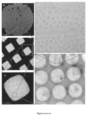
- Figures 2a to 2e illustrate imaging of a specimen prepared on a sample support such as that shown in Figure 1 at various level of magnification.
- Figure 2a shows the macroscopic structure of a grid forming part of a sample support. It can be seen in Figure 2a that there may be some damage or inconsistency across the grid. There are, as can be seen, some darkened grid squares.
- Figure 2b is an image of a few of the grid squares of the sample support of Figure 2a , in which the structure of the porous film can begin to be seen.
- Figure 2c shows the structure of the holey carbon within a single grid square.
- Figure 2d shows a plurality of pores of the holey carbon.
- Figure 2e shows an image of proteins within a single pore of the holey carbon.
- an electron microscopy sample or specimen is prepared for imaging in the following manner: a fluid, which includes the sample or specimen to be imaged, is manually placed upon a metal grid sample support, for example, by means of a pipette.
- the fluid wets and saturates the grid, filling the grid squares and, more particularly, the pores within the holey carbon within the grid holes.
- Excess fluid is removed and the sample support is cooled such that the fluid containing the sample is vitrified.
- the sample support, including the sample fluid is then stored until an imaging slot is available at an electron microscope.
- Typical success rate for a "good" grid (ie one in which a sample can be clearly imaged) prepared in accordance with a blotting method is 1-2 in every 10 grids prepared. Furthermore, it will be appreciated that the final results of the sample preparation according to the blotting technique for removal of excess sample fluid may only be evaluated in the electron microscope, an instrument that is not suitable for high throughput analysis. In other words, no quality control of prepared grids occurs until the grids reach the electron microscope for actual imaging. Consequently, sample grid preparation is currently one of the most significant bottlenecks in cryo-EM structure determination.
- samples may comprise, for example, samples for single particle or single protein cryo-EM.
- Devices may implement methods which use a controlled flow of gas, perhaps in a short burst, or "puff", to remove, for example, excess liquid from a sample grid.
- Use of a flow of gas may provide for several advantages in comparison to a method which uses filter paper for blotting. In particular: because it is possible to accurately define physical characteristics of the gas flow, for example, the pressure and the time of the puff of gas, it is possible to obtain more reproducible results from sample preparation.
- the directionality of the gas stream may result in a fine gradient in the thickness of the sample layer being created over the width of the grid, therefore increasing the chances of getting the right thickness of fluid supporting the sample at some point on each and every grid which is prepared.
- a high resolution camera may monitor and record a grid and sample during a preparation process. Such monitoring may enable users to connect the visible properties of a grid during preparation to the final quality of the grid as observed in the cryo-electron microscope. This way, if it is found that suboptimal conditions are used during the preparation of a sample grid, it may be clearer which preparation parameters to change.
- Such an option may make grid preparation methods less of a "hit-and-miss" procedure, and instead provide an accurately defined technique that takes the uncertainty out of the sample preparation for microscopy techniques, including cryo-EM techniques.
- the gas flow sample preparation technique also has several further advantages including the possibility of requiring a smaller sample volume, the possibility, in some embodiments, to use an alternative freezing/vitrification technique (one not reliant on plunging into liquid ethane) and incorporation of the preparation device into the microscope such that sample preparation and sample imaging become one and the same process. Ultimately, it may be possible that a user will only have to provide a sample, after which the subsequent steps can be performed without user intervention.
- the gas flow sample preparation technique may, in one implementation, comprise part of a sample preparation device which utilises a plunge-freezing/vitrification arrangement to vitrify a sample grid for cryo-EM.
- the sample preparation device may be configured to use a short burst or "puff" of compressed gas to remove excess sample fluid from a sample grid, leaving only a thin layer suitable for cryo-EM imaging.
- sample preparation devices use filter paper to remove the excess of sample via a blotting method and are notoriously irreproducible. It has been recognised that using a gas stream in relation to sample preparation may give better control over various factors that may affect the quality of the sample which, in turn, may offer more reliable microscopy results.
- Some implementations of a device may include imaging apparatus, such as a video camera, configured to monitor and record the sample grid during a preparation process. Such a recording may provide immediate feedback to a user regarding the likely quality of the sample.
- imaging apparatus such as a video camera
- Such a recording may provide immediate feedback to a user regarding the likely quality of the sample.
- Traditional methods which use filter paper to "blot" cannot be similarly directly monitored since the filter paper blocks any view of the sample grid and therefore the quality of the resulting sample grid can only be properly monitored once mounted into a cryo electron microscope, hours or even days after preparation of the sample grid.
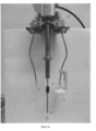
- FIG. 3 illustrates main components of a device according to one arrangement.
- the device shown comprises an electron microscopy sample preparation apparatus 1.
- the apparatus comprises: a support holder configured to receive an electron microscopy sample support 80.
- the electron microscopy sample support (not shown in Figure 3 ) may comprise a sample support such as those shown in Figures 1 and 2 .
- the sample support is configured to receive a fluid sample.
- the fluid sample may comprise, for example, a protein to be studied suspended in the fluid.
- the apparatus further comprises a gas outlet 20 configured to direct a flow of gas towards a surface of said electron microscopy sample support.
- the gas outlet 20 may comprise a nozzle which is configured to produce a flow of gas which adjusts the fluid sample supported by the electron microscopy sample support.
- the apparatus comprises two gas outlets 20, arranged substantially symmetrically about the support holder 10.
- the apparatus shown in Figure 3 comprises a plunge-freeze device for vitrificaton of a sample support including a fluid sample after preparation according to gas flow arrangements described herein.
- the arrangement shown is such that the apparatus further comprises a shield 30 arranged to receive any fluid removed from a sample support by a short burst of gas from a nozzle 20.
- the shield is movable such that when the sample (not shown) is plunged into liquid ethane (also not shown) in order to vitrify the fluid containing a specimen to be imaged in situ on the sample support, the shield does not impede movement of the sample support from the region of the gas outlets to the liquid ethane.
- the apparatus shown in Figure 3 further comprises camera 40 configured to record one or more images of a support located in the sample support holder 10.
- Operation of an arrangement such as the one shown in Figure 3 is such that a sample grid is placed in the sample support holder 10.
- a user may use a pipette to transfer or dispense a fluid sample onto the sample support.
- Two compressed gas streams are expelled from gas outlets 20 placed, in the example apparatus shown, at a slight angle (around 20 degrees) with respect to a surface of the sample grid supported by the support holder.
- the incident gas streams are used to remove excess fluid sample from the sample support. Removal of excess fluid may help to create a thin layer of sample fluid being supported on the support grid.
- the outlets 20 are configured to dispense a flow of compressed nitrogen gas, but it will be appreciated that other generally inert gases may be used as appropriate.
- some arrangements and implementations may allow for control of the humidity of a gas stream, to control the rate of evaporation of fluid from the sample support on continued exposure to the gas flow after removal of excess fluid.
- two gas nozzles deliver a flow of gas (one on each side) to the surfaces of the grid simultaneously to ensure the sample support remains in a desired position and that sample fluid adjustment by the gas flows is substantially symmetrical.
- the sample grid may be released or moved into liquid ethane.
- the two gas nozzles 20 are connected to the plunge-trigger and are configured so that they, and the shield 30 move out of the way when the sample plunges towards liquid ethane (not shown).
- Provision of imaging apparatus 40 in the arrangement shown in Figure 3 comprises provision of video recording apparatus.
- Video recordal of the EM sample grid can allow for continuous real-time monitoring of the sample, giving direct feedback about the likely resulting quality of the fluid sample supported by the grid.
- FIGs 4a to 4c illustrate schematically operation of main components of the device of Figure 3 when preparing a microscopy sample.
- two gas nozzles 20 are located in close proximity to the tip of tweezers forming the sample holder 10 in the example apparatus illustrated in Figure 3 .
- the sample holder will, when the apparatus is in use, hold a sample grid (not shown, but located in the region annotated A throughout Figure 4 .
- a shield 30 is provided below the grid and prevents the removed sample fluid from ending up in a bath of liquid ethane (not shown) typically located beneath the sample support holder.
- a mechanism 50 is provided to move the gas outlets 20 and shield 30 with respect to the sample holder 10, thus ensuring that the gas nozzles and shield are moved out of place and the tweezers can plunge down into liquid ethane (not shown) without obstruction.
- Figure 4a shows the device in a closed state, as it would be during fluid sample adjustment, such as removal of the excess of the sample and subsequent adjustment of the fluid on the sample support using a controlled flow of gas.
- Figure 4b shows the device in an open state in which the gas nozzles 20 and shield 30 are displaced by mechanism 50 such that the tweezers 10 holding the sample grid can move freely in a vertical or horizontal direction.
- Figure 4c shows the device in an open state in which the tweezers 10 have been moved downwards by mechanism 50 so that a sample support can be moved towards and into a bath of liquid ethane to achieve rapid sample support vitrification (not shown).
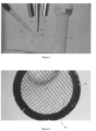
- Figure 5 illustrates introduction of a sample or specimen fluid to a sample support received by a device such as that shown in Figure 3 .
- a pipette 60 is used to place a sample fluid 70 on support grid 80. It will be appreciated that some arrangements may allow for automatic dispensing of a sample onto a grid.
- FIG 6 is a view of a sample support as recorded by imaging apparatus included in a device such as that shown in Figure 3 .
- the sample support 80 comprises a grid onto which sample fluid 70 has been dispensed. Provision of an imaging device 40 allows for analysis of the behaviour of the sample fluid 70 after it has been dispensed onto the grid 80, through a wait period, during which the fluid sample can be seen to "wet" the grid, through an active period, during which a gas flow is applied to the surface of the sample support and excess fluid is removed, and evaporation may occur, until cessation of an applied gas flow and through a relaxation period, between cessation of the gas flow and vitrification of a fluid sample on a sample support, during which the fluid may "relax" and redistribute itself upon the sample support.
- figures 7a to 7c show behaviour of a sample on a sample support used in a device such as that shown in Figure 3 based on images captured, using imaging apparatus 40, of a sample fluid 70 after it has been dispensed onto the grid 80 and exposed to a gas flow from nozzles 20.
- Figures 7a to 7c provide an example of images captured using video which show movement of a wavefront across the grid when the fluid placed on the grid is subjected to a gas flow.
- Video analysis of operation of an apparatus similar to that shown in Figure 3 indicates that various stages occur in relation to the interaction between fluid placed on to a support and a flow of gas directed toward the sample support.
- the flow of gas initially operates to remove excess sample fluid. That is to say, any residual bead of fluid sample which is present on the surface of the support is removed. Fluid sample which has wet/entered the grid spaces is typically not removed, provided the direction of the flow of gas is selected appropriately.
- FIG. 8a illustrates schematically in cross section the typical behaviour of a fluid sample 70 between grid support bars 90.
- Such a gradient achieved across a sample support may be beneficial since it may ensure that somewhere on the support it is likely that an optimum fluid thickness for imaging a specimen within the fluid may be achieved.
- FIG. 8b illustrates schematically in cross section the typical behaviour of a fluid sample 70 between grid support bars 90 after removal of a gas flow.
- a sample support including fluid sample may be vitrified.
- vitrification is achieved by plunging the sample support into a bath of liquid ethane. It is recognised that in some arrangements it may be possible to use an appropriately selected further gas flow to achieve vitrification.
- Figure 9 illustrates a component of a device such as that shown in Figure 3 .
- apparatus may be provided with a means to implement different variable time settings in relation to the different steps which occur during sample preparation process.
- Figure 9 shows an electronic switch allows for the setting of different times for: i) a wait time ("wait period") between application of a fluid sample to a support and initiation of a gas flow, such that the fluid sample can, for example, interact with a grid; ii) the duration of an applied gas flow ("active period”); and iii) a "relaxation” wait time (“relaxation period”) between cessation of gas flow and a time at which the sample support is vitrified, for example by plunging the grid into liquid ethane.
- wait period a wait time
- active period the duration of an applied gas flow
- relaxation period a "relaxation" wait time
- the direction of the flow may be of significance.
- a gas flow substantially parallel to the surface of the sample support may achieve efficient removal of excess fluid sample.
- Application of a gas flow substantially perpendicular to the surface of the sample support may allow for a droplet of sample to be uniformly spread across the sample, and/or may allow for more uniform evaporation or cooling, as desired.
- the angle of incidence of a gas flow upon a sample support surface may be fixed or may be adjustable.
- the direction of gas flow applied to a sample may be adjusted during different phases of preparation.
- the rate of gas flow, width of gas flow and nature of gas flow may influence operation of a device.
- the rate of gas flow may be adjustable.
- the nozzle or outlet may, in some arrangements, be shaped to ensure a uniform laminar gas flow is incident across the surface of the sample support.
- the type of gas used may be controlled.
- the humidity of the gas flow may be adjusted to control, for example, sample fluid evaporation.
- the temperature of the device and ambient surroundings may be controlled, again to ensure reproducibility of electron microscopy sample preparation.
- symmetrical gas flows may be applied to opposing surfaces of a sample support (such as in the arrangement of Figure 3 ).
- a single gas outlet may be provided.
- the single gas outlet may, for example, also be arranged to apply a gas flow symmetrically to opposing surfaces of a sample support.
- a single gas flow outlet may be configured to supply a gas flow to a single surface of the sample support to adjust the fluid sample.
- a single gas flow outlet may be configured to supply a gas flow to a single surface of the sample support to cool the fluid sample.
- a cold nitrogen gas stream at 100 Kelvin may be applied to a sample support surface to vitrify the sample grid and fluid supported on the grid.
- Some arrangements may allow for automatic fluid sample application to a sample support, rather than requiring a user to manually pipette a sample fluid into position on a sample support. Automation of the fluid application may allow for use of smaller sample volumes. Manual application of the sample requires a volume of ⁇ 3 microlitres be deposited onto the grid. The majority of that sample will typically be removed during the puff of gas. Using nanolitre deposition techniques such as those used in protein crystallization robotics may allow for reduction of required sample volume approximately 10-fold, thereby saving precious sample.
- the fluid sample comprises those specimens mentioned above and, in particular, ribosome small subunits, polymerase-DNA complexes, transcription factor-DNA complexes, protein samples, biological specimens, macromolecules, etc.
- the specimens are provided within a suspension fluid typically at around a 3 - 10 micromolar concentration.
- the specimen concentration is selected to provide typically a few specimens (such as macromolecules) present in each aperture in the sample support.
- Embodiments recognise that in order to be able to construct an accurate image of a specimen (such as a macromolecule), the specimens need to be cryogenically suspended in a near-natural form and in multiple orientations in order to be able to build up a 3-dimensional image from imaging multiple specimens.
- a specimen such as a macromolecule
- embodiments recognise that disassociation of macromolecular complexes, subcomplexes, ligands, co-factors, etc, once the sample fluid has been received on the sample support, can occur. Also, evaporation of fluid, once the fluid sample is received by the support holder, can change buffer conditions that may be detrimental to the macro-molecule (such as increasing in salt concentration, changes in pH, etc).
- the macro-molecules can interact with the air-liquid interface and become bound in a preferred orientation.
- embodiments seek to complete all processes between the fluid sample being deposited on the sample support and then being vitrified within a processing time period which eliminates or minimises the degree of disassociation and/or evaporation of fluid and/or reorientation to the preferred orientation.
- processing of the fluid sample on the sample support seeks to minimise change in concentration of the specimen within the sample.
- concentration of specimens within the fluid is selected in order that a suitable number of specimens are present in each aperture of the sample support.
- an automated arrangement for rapidly depositing, cleaving and vitrifying the fluid sample.
- the time from deposition onto the grid to vitrification should be in the sub-second range and typically less than around 100 ms.
- the automated arrangement is similar to that described above; however, an electromechanical injector (such as a small volume (25-100 microlitre) syringe) is used in place of the pipette 60 at a position of around 10mm from the support grid to inject the sample fluid 70 onto the support grid 80.
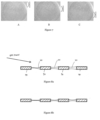
- Figure 10 is a timing diagram showing the timing of the automated arrangement.
- a 3 microlitre sample fluid is deposited by the electromechanical injector over a depositing period of between around 20 to 30 ms and more typically between around 10 to 15 ms.
- An optional delay of up to 10 ms may occur following this deposition.
- the gas flow is applied from the gas nozzles 20 at a typical pressure of around between around 2 to 4 bar for a cleaving period around 10 to 20 ms. This cleaves the sample fluid, with excess sample fluid being separated or split from the remainder of the sample fluid which remains on the support grid 80. Once the cleaving has finished then the support grid 80 is translated so that it is received within the cooling bath within a vitrifying period of less than around 50 ms during which virtification occurs.
- embodiments shorten the time between sample application (the injection), the sample cleaving (the 'puff') and sample vitrifying (the plunge) to the millisecond time scale.
- the total handling time approaches the frequency by which the macro-molecules under study interact with the air-liquid interface and remain bound in a preferred orientation.
- the number of air-water interface interactions are minimised which minimises the number of molecules bound in that preferred orientation.
- the contribution of evaporation of the sample is strongly reduced. This prevents changes in buffer conditions that may be detrimental to the macro-molecule (such as increase of salt concentration, changes in pH).
- This approach also allows for higher starting concentrations of the sample to be used (as it is no longer being concentrated during the grid preparation process), which is beneficial to weakly binding complexes that fall apart at lower concentrations.
- the timing may need to be varied based on the viscosity of the fluid sample; more viscous samples may need a longer puff of the gas nozzles 20.
- the support grid 80 can be made less hydrophylic by shortening the treatment time in the plasma chamber (i.e. glow discharge).
- the characteristics of the gas flow to achieve cleaving may be adjusted based on the physical arrangement of the apparatus and properties of the fluid sample.
- the support grid 80 is monitored by high resolution / high speed cameras which follow the sample deposition and sample cleaving.
- the final quality of the sample grid 80 is monitored by cryo-electron microscopy.
- the gas valves are located to be immediately in front of the gas nozzles 20.
- a strong (2-4 MBar) blast (puff) of gas is used to remove the excess of sample by force (not evaporation) from a cryo-EM grid.
- the gas stream may be parallel, under an angle, or perpendicular to the surface of the cryo-EM grid.
- Sample deposition, excess sample removal and vitrifying of sample occurs in such a manner that the whole procedure takes place at the sub-second time frame in order to: 1) prevent/reduce preferential orientation of the sample/macromolecule under investigation and/or 2) prevent/reduce dissociation of macromolecular complex, sub-complexes, ligands, co-factors etc. and/or 3) prevent/reduce evaporation of the sample.
Landscapes
- Chemical & Material Sciences (AREA)
- Health & Medical Sciences (AREA)
- Analytical Chemistry (AREA)
- General Health & Medical Sciences (AREA)
- Life Sciences & Earth Sciences (AREA)
- Biochemistry (AREA)
- Physics & Mathematics (AREA)
- General Physics & Mathematics (AREA)
- Immunology (AREA)
- Pathology (AREA)
- Chemical Kinetics & Catalysis (AREA)
- Clinical Laboratory Science (AREA)
- Hematology (AREA)
- Engineering & Computer Science (AREA)
- Biomedical Technology (AREA)
- Molecular Biology (AREA)
- Sampling And Sample Adjustment (AREA)
- Analysing Materials By The Use Of Radiation (AREA)
Applications Claiming Priority (2)
| Application Number | Priority Date | Filing Date | Title |
|---|---|---|---|
| GBGB1613173.2A GB201613173D0 (en) | 2016-07-29 | 2016-07-29 | Electron microscopy |
| PCT/EP2017/069240 WO2018020036A1 (en) | 2016-07-29 | 2017-07-28 | Electron microscopy |
Publications (2)
| Publication Number | Publication Date |
|---|---|
| EP3491360A1 EP3491360A1 (en) | 2019-06-05 |
| EP3491360B1 true EP3491360B1 (en) | 2025-03-19 |
Family
ID=56936668
Family Applications (1)
| Application Number | Title | Priority Date | Filing Date |
|---|---|---|---|
| EP17745722.3A Active EP3491360B1 (en) | 2016-07-29 | 2017-07-28 | Electron microscopy |
Country Status (10)
| Country | Link |
|---|---|
| US (1) | US11067486B2 (enExample) |
| EP (1) | EP3491360B1 (enExample) |
| JP (1) | JP6997757B2 (enExample) |
| CN (1) | CN109891208A (enExample) |
| AU (1) | AU2017302126B2 (enExample) |
| CA (1) | CA3032234C (enExample) |
| DK (1) | DK3491360T3 (enExample) |
| ES (1) | ES3026360T3 (enExample) |
| GB (1) | GB201613173D0 (enExample) |
| WO (1) | WO2018020036A1 (enExample) |
Families Citing this family (7)
| Publication number | Priority date | Publication date | Assignee | Title |
|---|---|---|---|---|
| EP3647763B1 (en) | 2018-10-29 | 2021-07-14 | FEI Company | A method of preparing a biological sample for study in an analysis device |
| CN111389478B (zh) * | 2020-03-23 | 2023-07-25 | 西安医学院 | 一种组织切片的实验处理装置及其使用方法 |
| GB2593491A (en) * | 2020-03-24 | 2021-09-29 | Res & Innovation Uk | Electron microscopy support |
| EP4109069A1 (en) | 2021-06-25 | 2022-12-28 | FEI Company | Blotting material with profiled region, method of manufacturing same, and uses thereof |
| WO2023220061A1 (en) * | 2022-05-13 | 2023-11-16 | The Board Of Trustees Of The Leland Stanford Junior University | Cold gas stream method for cryoem sample grid vitrification |
| NL2033291B1 (en) | 2022-10-12 | 2024-04-26 | Academisch Ziekenhuis Leiden | Device and Method for Cryogenic Electron Microscopy Sample Preparation |
| EP4711738A1 (en) * | 2024-09-17 | 2026-03-18 | European Molecular Biology Laboratory | Sample preparation method and device for preparing a vitrified sample layer on a sample holder grid for subsequent cryo electron microscopy |
Citations (1)
| Publication number | Priority date | Publication date | Assignee | Title |
|---|---|---|---|---|
| EP3260839A1 (en) * | 2016-06-22 | 2017-12-27 | Universiteit Maastricht | Method of and apparatus for preparing samples for imaging or diffraction experiments under cryogenic conditions |
Family Cites Families (21)
| Publication number | Priority date | Publication date | Assignee | Title |
|---|---|---|---|---|
| JPS59109840A (ja) | 1982-12-16 | 1984-06-25 | Hitachi Koki Co Ltd | 走査形電子顕微鏡用生物試料の前処理方法 |
| US7112790B1 (en) * | 2003-08-13 | 2006-09-26 | Cypress Semiconductor Corp. | Method to prepare TEM samples |
| JP2007163447A (ja) * | 2005-12-09 | 2007-06-28 | Lee Bing Huan | 電子顕微鏡用の超薄液体制御板 |
| JP4891830B2 (ja) * | 2007-04-18 | 2012-03-07 | 日本電子株式会社 | 電子顕微鏡用試料ホルダおよび観察方法 |
| WO2009065585A2 (en) * | 2007-11-20 | 2009-05-28 | MAX-PLANCK-Gesellschaft zur Förderung der Wissenschaften e.V. | Ultra-rapid freezing device and method |
| GB0724736D0 (en) * | 2007-12-19 | 2008-01-30 | Oxford Nanolabs Ltd | Formation of layers of amphiphilic molecules |
| GB2461708A (en) * | 2008-07-08 | 2010-01-13 | Silson Ltd | Sample holder |
| JP2010054272A (ja) | 2008-08-27 | 2010-03-11 | National Institute Of Advanced Industrial Science & Technology | スピン偏極走査電子顕微鏡 |
| AT507079B1 (de) * | 2009-01-22 | 2010-02-15 | Leica Mikrosysteme Gmbh | Vorrichtung und verfahren zum präparieren von proben |
| JP5550262B2 (ja) * | 2009-05-29 | 2014-07-16 | キヤノン株式会社 | 試料観察システム及び試料観察方法 |
| US9312095B2 (en) * | 2010-03-24 | 2016-04-12 | Brown University | Method and system for automating sample preparation for microfluidic cryo TEM |
| GB201118282D0 (en) | 2011-10-21 | 2011-12-07 | Cancer Rec Tech Ltd | Sample slide preparation method and device |
| JP5930922B2 (ja) * | 2012-09-14 | 2016-06-08 | 株式会社日立ハイテクノロジーズ | 荷電粒子線装置及び試料観察方法 |
| JP6239246B2 (ja) * | 2013-03-13 | 2017-11-29 | 株式会社日立ハイテクノロジーズ | 荷電粒子線装置、試料観察方法、試料台、観察システム、および発光部材 |
| US10157725B2 (en) * | 2013-08-13 | 2018-12-18 | United Kingdom Research And Innovation | Electron microscopy sample support including porous metal foil |
| GB201318463D0 (en) * | 2013-08-13 | 2013-12-04 | Medical Res Council | Graphene Modification |
| EP2853847B1 (en) * | 2013-09-30 | 2016-02-03 | Fei Company | Preparation of cryogenic sample for charged-particle microscopy |
| WO2015086485A1 (en) | 2013-12-13 | 2015-06-18 | Ventana Medical Systems, Inc. | Thermal management in the context of automated histological processing of biological specimens and associated technology |
| GB2537579A (en) | 2014-11-07 | 2016-10-26 | Linkam Scient Instr Ltd | Microscopic sample preparation |
| WO2016170008A1 (en) * | 2015-04-20 | 2016-10-27 | Ventana Medical Systems, Inc. | Inkjet deposition of reagents for histological samples |
| EP3647763B1 (en) * | 2018-10-29 | 2021-07-14 | FEI Company | A method of preparing a biological sample for study in an analysis device |
-
2016
- 2016-07-29 GB GBGB1613173.2A patent/GB201613173D0/en not_active Ceased
-
2017
- 2017-07-28 EP EP17745722.3A patent/EP3491360B1/en active Active
- 2017-07-28 CA CA3032234A patent/CA3032234C/en active Active
- 2017-07-28 AU AU2017302126A patent/AU2017302126B2/en active Active
- 2017-07-28 DK DK17745722.3T patent/DK3491360T3/da active
- 2017-07-28 ES ES17745722T patent/ES3026360T3/es active Active
- 2017-07-28 WO PCT/EP2017/069240 patent/WO2018020036A1/en not_active Ceased
- 2017-07-28 CN CN201780047251.7A patent/CN109891208A/zh active Pending
- 2017-07-28 JP JP2019503570A patent/JP6997757B2/ja active Active
- 2017-07-28 US US16/320,961 patent/US11067486B2/en active Active
Patent Citations (1)
| Publication number | Priority date | Publication date | Assignee | Title |
|---|---|---|---|---|
| EP3260839A1 (en) * | 2016-06-22 | 2017-12-27 | Universiteit Maastricht | Method of and apparatus for preparing samples for imaging or diffraction experiments under cryogenic conditions |
Also Published As
| Publication number | Publication date |
|---|---|
| CN109891208A (zh) | 2019-06-14 |
| US20190170618A1 (en) | 2019-06-06 |
| JP2019528435A (ja) | 2019-10-10 |
| EP3491360A1 (en) | 2019-06-05 |
| JP6997757B2 (ja) | 2022-02-04 |
| ES3026360T3 (en) | 2025-06-11 |
| AU2017302126B2 (en) | 2022-07-07 |
| GB201613173D0 (en) | 2016-09-14 |
| WO2018020036A1 (en) | 2018-02-01 |
| AU2017302126A1 (en) | 2019-02-07 |
| CA3032234C (en) | 2024-02-13 |
| US11067486B2 (en) | 2021-07-20 |
| DK3491360T3 (da) | 2025-06-10 |
| CA3032234A1 (en) | 2018-02-01 |
Similar Documents
| Publication | Publication Date | Title |
|---|---|---|
| EP3491360B1 (en) | Electron microscopy | |
| CN109690281B (zh) | 制备用于低温条件下成像或衍射实验的样本的方法和设备 | |
| US20140360286A1 (en) | Apparatus and Method for Producing Specimens for Electron Microscopy | |
| US7531797B2 (en) | Probe-holding apparatus, sample-obtaining apparatus, sample-processing apparatus, sample-processing method and sample-evaluating method | |
| CN110062880A (zh) | 通过受控样品蒸发制备无损冷冻载网 | |
| EP2853847B1 (en) | Preparation of cryogenic sample for charged-particle microscopy | |
| EP2878008B1 (en) | Ion beam sample preparation apparatus and methods | |
| CN100495634C (zh) | 信息获取装置、截面评估装置、以及截面评估方法 | |
| JPWO2014175074A1 (ja) | 荷電粒子線装置及び当該装置を用いる試料作製方法 | |
| EP3023762B1 (en) | Specimen holder and specimen preparation device | |
| JP2007333682A (ja) | イオンビームを用いた断面試料作製装置 | |
| JP3715956B2 (ja) | 情報取得装置、試料評価装置および試料評価方法 | |
| JP2019528435A5 (enExample) | ||
| JP2008544240A (ja) | レーザ顕微解剖方法及びレーザ顕微解剖用の装置 | |
| WO2021217274A1 (en) | High-speed cryoem specimen preparation using through-grid wicking | |
| WO2024080868A1 (en) | Device and method for cryogenic electron microscopy sample preparation | |
| JP2002150984A (ja) | 試料ホルダー | |
| EP3885756B1 (en) | Soaking machine and soaking method of sample for single-crystal x-ray structure analysis | |
| JP2002144298A (ja) | マニピュレータ、物体接続・分離方法及び物体接続・分離装置 |
Legal Events
| Date | Code | Title | Description |
|---|---|---|---|
| STAA | Information on the status of an ep patent application or granted ep patent |
Free format text: STATUS: UNKNOWN |
|
| STAA | Information on the status of an ep patent application or granted ep patent |
Free format text: STATUS: THE INTERNATIONAL PUBLICATION HAS BEEN MADE |
|
| PUAI | Public reference made under article 153(3) epc to a published international application that has entered the european phase |
Free format text: ORIGINAL CODE: 0009012 |
|
| STAA | Information on the status of an ep patent application or granted ep patent |
Free format text: STATUS: REQUEST FOR EXAMINATION WAS MADE |
|
| 17P | Request for examination filed |
Effective date: 20190226 |
|
| AK | Designated contracting states |
Kind code of ref document: A1 Designated state(s): AL AT BE BG CH CY CZ DE DK EE ES FI FR GB GR HR HU IE IS IT LI LT LU LV MC MK MT NL NO PL PT RO RS SE SI SK SM TR |
|
| AX | Request for extension of the european patent |
Extension state: BA ME |
|
| DAV | Request for validation of the european patent (deleted) | ||
| DAX | Request for extension of the european patent (deleted) | ||
| RIN1 | Information on inventor provided before grant (corrected) |
Inventor name: FERNANDEZ-LEIRO, RAFAEL Inventor name: FIRMAN, JOSHUA Inventor name: LAMERS, MEINDERT, HUGO |
|
| REG | Reference to a national code |
Ref country code: HK Ref legal event code: DE Ref document number: 40009609 Country of ref document: HK |
|
| STAA | Information on the status of an ep patent application or granted ep patent |
Free format text: STATUS: EXAMINATION IS IN PROGRESS |
|
| 17Q | First examination report despatched |
Effective date: 20211001 |
|
| GRAP | Despatch of communication of intention to grant a patent |
Free format text: ORIGINAL CODE: EPIDOSNIGR1 |
|
| STAA | Information on the status of an ep patent application or granted ep patent |
Free format text: STATUS: GRANT OF PATENT IS INTENDED |
|
| INTG | Intention to grant announced |
Effective date: 20241015 |
|
| RIN1 | Information on inventor provided before grant (corrected) |
Inventor name: FIRMAN, JOSHUA Inventor name: FERNANDEZ-LEIRO, RAFAEL Inventor name: LAMERS, MEINDERT, HUGO |
|
| GRAS | Grant fee paid |
Free format text: ORIGINAL CODE: EPIDOSNIGR3 |
|
| GRAA | (expected) grant |
Free format text: ORIGINAL CODE: 0009210 |
|
| STAA | Information on the status of an ep patent application or granted ep patent |
Free format text: STATUS: THE PATENT HAS BEEN GRANTED |
|
| AK | Designated contracting states |
Kind code of ref document: B1 Designated state(s): AL AT BE BG CH CY CZ DE DK EE ES FI FR GB GR HR HU IE IS IT LI LT LU LV MC MK MT NL NO PL PT RO RS SE SI SK SM TR |
|
| REG | Reference to a national code |
Ref country code: GB Ref legal event code: FG4D |
|
| REG | Reference to a national code |
Ref country code: CH Ref legal event code: EP |
|
| REG | Reference to a national code |
Ref country code: DE Ref legal event code: R096 Ref document number: 602017088399 Country of ref document: DE |
|
| P01 | Opt-out of the competence of the unified patent court (upc) registered |
Free format text: CASE NUMBER: APP_10517/2025 Effective date: 20250303 |
|
| REG | Reference to a national code |
Ref country code: IE Ref legal event code: FG4D |
|
| REG | Reference to a national code |
Ref country code: NL Ref legal event code: FP |
|
| REG | Reference to a national code |
Ref country code: DK Ref legal event code: T3 Effective date: 20250606 |
|
| REG | Reference to a national code |
Ref country code: ES Ref legal event code: FG2A Ref document number: 3026360 Country of ref document: ES Kind code of ref document: T3 Effective date: 20250611 |
|
| REG | Reference to a national code |
Ref country code: SE Ref legal event code: TRGR |
|
| PG25 | Lapsed in a contracting state [announced via postgrant information from national office to epo] |
Ref country code: RS Free format text: LAPSE BECAUSE OF FAILURE TO SUBMIT A TRANSLATION OF THE DESCRIPTION OR TO PAY THE FEE WITHIN THE PRESCRIBED TIME-LIMIT Effective date: 20250619 |
|
| PG25 | Lapsed in a contracting state [announced via postgrant information from national office to epo] |
Ref country code: FI Free format text: LAPSE BECAUSE OF FAILURE TO SUBMIT A TRANSLATION OF THE DESCRIPTION OR TO PAY THE FEE WITHIN THE PRESCRIBED TIME-LIMIT Effective date: 20250319 |
|
| REG | Reference to a national code |
Ref country code: LT Ref legal event code: MG9D |
|
| PG25 | Lapsed in a contracting state [announced via postgrant information from national office to epo] |
Ref country code: NO Free format text: LAPSE BECAUSE OF FAILURE TO SUBMIT A TRANSLATION OF THE DESCRIPTION OR TO PAY THE FEE WITHIN THE PRESCRIBED TIME-LIMIT Effective date: 20250619 |
|
| PG25 | Lapsed in a contracting state [announced via postgrant information from national office to epo] |
Ref country code: HR Free format text: LAPSE BECAUSE OF FAILURE TO SUBMIT A TRANSLATION OF THE DESCRIPTION OR TO PAY THE FEE WITHIN THE PRESCRIBED TIME-LIMIT Effective date: 20250319 |
|
| PG25 | Lapsed in a contracting state [announced via postgrant information from national office to epo] |
Ref country code: LV Free format text: LAPSE BECAUSE OF FAILURE TO SUBMIT A TRANSLATION OF THE DESCRIPTION OR TO PAY THE FEE WITHIN THE PRESCRIBED TIME-LIMIT Effective date: 20250319 |
|
| PG25 | Lapsed in a contracting state [announced via postgrant information from national office to epo] |
Ref country code: GR Free format text: LAPSE BECAUSE OF FAILURE TO SUBMIT A TRANSLATION OF THE DESCRIPTION OR TO PAY THE FEE WITHIN THE PRESCRIBED TIME-LIMIT Effective date: 20250620 Ref country code: BG Free format text: LAPSE BECAUSE OF FAILURE TO SUBMIT A TRANSLATION OF THE DESCRIPTION OR TO PAY THE FEE WITHIN THE PRESCRIBED TIME-LIMIT Effective date: 20250319 |
|
| REG | Reference to a national code |
Ref country code: AT Ref legal event code: MK05 Ref document number: 1777307 Country of ref document: AT Kind code of ref document: T Effective date: 20250319 |
|
| PGFP | Annual fee paid to national office [announced via postgrant information from national office to epo] |
Ref country code: NL Payment date: 20250722 Year of fee payment: 9 |
|
| PG25 | Lapsed in a contracting state [announced via postgrant information from national office to epo] |
Ref country code: SM Free format text: LAPSE BECAUSE OF FAILURE TO SUBMIT A TRANSLATION OF THE DESCRIPTION OR TO PAY THE FEE WITHIN THE PRESCRIBED TIME-LIMIT Effective date: 20250319 |
|
| PG25 | Lapsed in a contracting state [announced via postgrant information from national office to epo] |
Ref country code: PT Free format text: LAPSE BECAUSE OF FAILURE TO SUBMIT A TRANSLATION OF THE DESCRIPTION OR TO PAY THE FEE WITHIN THE PRESCRIBED TIME-LIMIT Effective date: 20250721 |
|
| PGFP | Annual fee paid to national office [announced via postgrant information from national office to epo] |
Ref country code: ES Payment date: 20250801 Year of fee payment: 9 |
|
| PGFP | Annual fee paid to national office [announced via postgrant information from national office to epo] |
Ref country code: DK Payment date: 20250721 Year of fee payment: 9 Ref country code: DE Payment date: 20250724 Year of fee payment: 9 |
|
| PG25 | Lapsed in a contracting state [announced via postgrant information from national office to epo] |
Ref country code: PL Free format text: LAPSE BECAUSE OF FAILURE TO SUBMIT A TRANSLATION OF THE DESCRIPTION OR TO PAY THE FEE WITHIN THE PRESCRIBED TIME-LIMIT Effective date: 20250319 |
|
| PGFP | Annual fee paid to national office [announced via postgrant information from national office to epo] |
Ref country code: IT Payment date: 20250722 Year of fee payment: 9 |
|
| PGFP | Annual fee paid to national office [announced via postgrant information from national office to epo] |
Ref country code: GB Payment date: 20250722 Year of fee payment: 9 |
|
| PG25 | Lapsed in a contracting state [announced via postgrant information from national office to epo] |
Ref country code: AT Free format text: LAPSE BECAUSE OF FAILURE TO SUBMIT A TRANSLATION OF THE DESCRIPTION OR TO PAY THE FEE WITHIN THE PRESCRIBED TIME-LIMIT Effective date: 20250319 |
|
| PGFP | Annual fee paid to national office [announced via postgrant information from national office to epo] |
Ref country code: FR Payment date: 20250722 Year of fee payment: 9 |
|
| PGFP | Annual fee paid to national office [announced via postgrant information from national office to epo] |
Ref country code: CH Payment date: 20250801 Year of fee payment: 9 Ref country code: SE Payment date: 20250721 Year of fee payment: 9 |
|
| PG25 | Lapsed in a contracting state [announced via postgrant information from national office to epo] |
Ref country code: EE Free format text: LAPSE BECAUSE OF FAILURE TO SUBMIT A TRANSLATION OF THE DESCRIPTION OR TO PAY THE FEE WITHIN THE PRESCRIBED TIME-LIMIT Effective date: 20250319 Ref country code: CZ Free format text: LAPSE BECAUSE OF FAILURE TO SUBMIT A TRANSLATION OF THE DESCRIPTION OR TO PAY THE FEE WITHIN THE PRESCRIBED TIME-LIMIT Effective date: 20250319 |
|
| PGFP | Annual fee paid to national office [announced via postgrant information from national office to epo] |
Ref country code: IE Payment date: 20250724 Year of fee payment: 9 |
|
| PG25 | Lapsed in a contracting state [announced via postgrant information from national office to epo] |
Ref country code: RO Free format text: LAPSE BECAUSE OF FAILURE TO SUBMIT A TRANSLATION OF THE DESCRIPTION OR TO PAY THE FEE WITHIN THE PRESCRIBED TIME-LIMIT Effective date: 20250319 |
|
| PG25 | Lapsed in a contracting state [announced via postgrant information from national office to epo] |
Ref country code: SK Free format text: LAPSE BECAUSE OF FAILURE TO SUBMIT A TRANSLATION OF THE DESCRIPTION OR TO PAY THE FEE WITHIN THE PRESCRIBED TIME-LIMIT Effective date: 20250319 |
|
| PG25 | Lapsed in a contracting state [announced via postgrant information from national office to epo] |
Ref country code: IS Free format text: LAPSE BECAUSE OF FAILURE TO SUBMIT A TRANSLATION OF THE DESCRIPTION OR TO PAY THE FEE WITHIN THE PRESCRIBED TIME-LIMIT Effective date: 20250719 |
|
| REG | Reference to a national code |
Ref country code: DE Ref legal event code: R097 Ref document number: 602017088399 Country of ref document: DE |
|
| PLBE | No opposition filed within time limit |
Free format text: ORIGINAL CODE: 0009261 |
|
| STAA | Information on the status of an ep patent application or granted ep patent |
Free format text: STATUS: NO OPPOSITION FILED WITHIN TIME LIMIT |
|
| REG | Reference to a national code |
Ref country code: CH Ref legal event code: L10 Free format text: ST27 STATUS EVENT CODE: U-0-0-L10-L00 (AS PROVIDED BY THE NATIONAL OFFICE) Effective date: 20260128 |
|
| 26N | No opposition filed |
Effective date: 20251222 |
|
| PG25 | Lapsed in a contracting state [announced via postgrant information from national office to epo] |
Ref country code: LU Free format text: LAPSE BECAUSE OF NON-PAYMENT OF DUE FEES Effective date: 20250728 |
|
| REG | Reference to a national code |
Ref country code: BE Ref legal event code: MM Effective date: 20250731 |
|
| PG25 | Lapsed in a contracting state [announced via postgrant information from national office to epo] |
Ref country code: BE Free format text: LAPSE BECAUSE OF NON-PAYMENT OF DUE FEES Effective date: 20250731 |