EP3490236B1 - Abtastvorrichtung, bildgebungsvorrichtung und abtastverfahren - Google Patents
Abtastvorrichtung, bildgebungsvorrichtung und abtastverfahren Download PDFInfo
- Publication number
- EP3490236B1 EP3490236B1 EP17842731.6A EP17842731A EP3490236B1 EP 3490236 B1 EP3490236 B1 EP 3490236B1 EP 17842731 A EP17842731 A EP 17842731A EP 3490236 B1 EP3490236 B1 EP 3490236B1
- Authority
- EP
- European Patent Office
- Prior art keywords
- image data
- data
- image
- sensor
- channel
- Prior art date
- Legal status (The legal status is an assumption and is not a legal conclusion. Google has not performed a legal analysis and makes no representation as to the accuracy of the status listed.)
- Active
Links
Images


Classifications
-
- H—ELECTRICITY
- H04—ELECTRIC COMMUNICATION TECHNIQUE
- H04N—PICTORIAL COMMUNICATION, e.g. TELEVISION
- H04N1/00—Scanning, transmission or reproduction of documents or the like, e.g. facsimile transmission; Details thereof
- H04N1/00795—Reading arrangements
-
- H—ELECTRICITY
- H04—ELECTRIC COMMUNICATION TECHNIQUE
- H04N—PICTORIAL COMMUNICATION, e.g. TELEVISION
- H04N1/00—Scanning, transmission or reproduction of documents or the like, e.g. facsimile transmission; Details thereof
- H04N1/04—Scanning arrangements, i.e. arrangements for the displacement of active reading or reproducing elements relative to the original or reproducing medium, or vice versa
- H04N1/203—Simultaneous scanning of two or more separate pictures, e.g. two sides of the same sheet
- H04N1/2032—Simultaneous scanning of two or more separate pictures, e.g. two sides of the same sheet of two pictures corresponding to two sides of a single medium
-
- H—ELECTRICITY
- H04—ELECTRIC COMMUNICATION TECHNIQUE
- H04N—PICTORIAL COMMUNICATION, e.g. TELEVISION
- H04N1/00—Scanning, transmission or reproduction of documents or the like, e.g. facsimile transmission; Details thereof
- H04N1/00976—Arrangements for regulating environment, e.g. removing static electricity
-
- H—ELECTRICITY
- H04—ELECTRIC COMMUNICATION TECHNIQUE
- H04N—PICTORIAL COMMUNICATION, e.g. TELEVISION
- H04N1/00—Scanning, transmission or reproduction of documents or the like, e.g. facsimile transmission; Details thereof
- H04N1/024—Details of scanning heads ; Means for illuminating the original
- H04N1/02418—Details of scanning heads ; Means for illuminating the original for picture information pick up and reproduction
-
- H—ELECTRICITY
- H04—ELECTRIC COMMUNICATION TECHNIQUE
- H04N—PICTORIAL COMMUNICATION, e.g. TELEVISION
- H04N1/00—Scanning, transmission or reproduction of documents or the like, e.g. facsimile transmission; Details thereof
- H04N1/04—Scanning arrangements, i.e. arrangements for the displacement of active reading or reproducing elements relative to the original or reproducing medium, or vice versa
- H04N1/203—Simultaneous scanning of two or more separate pictures, e.g. two sides of the same sheet
-
- H—ELECTRICITY
- H04—ELECTRIC COMMUNICATION TECHNIQUE
- H04N—PICTORIAL COMMUNICATION, e.g. TELEVISION
- H04N1/00—Scanning, transmission or reproduction of documents or the like, e.g. facsimile transmission; Details thereof
- H04N1/23—Reproducing arrangements
- H04N1/2307—Circuits or arrangements for the control thereof, e.g. using a programmed control device, according to a measured quantity
- H04N1/233—Circuits or arrangements for the control thereof, e.g. using a programmed control device, according to a measured quantity according to characteristics of the data to be reproduced, e.g. number of lines
-
- H—ELECTRICITY
- H04—ELECTRIC COMMUNICATION TECHNIQUE
- H04N—PICTORIAL COMMUNICATION, e.g. TELEVISION
- H04N1/00—Scanning, transmission or reproduction of documents or the like, e.g. facsimile transmission; Details thereof
- H04N1/40—Picture signal circuits
Definitions
- the present invention relates to the field of image processing technologies, and in particular, to a scanning device, an image-forming apparatus, and a scanning method.
- the duplex document scanning apparatus includes a first image sensor, a second image sensor, a switch module, a data conversion unit, and a scanning control device.
- the first image sensor senses the first analog image signal
- the second image sensor senses the second analog image signal.
- the switch module switches the first image sensor and the second image sensor to select the first analog image signal and the second analog image signal.
- the data conversion unit converts the first and second analog image signals to generate first and second digital image signals.
- the switch control module of scanning control device generates a switch signal to control the switch module.
- the scanning control device has a switch control unit and processes the first digital image signal and a second digital image signal.
- the switch control unit generates a switch signal for controlling the switch module and the switch module simultaneously outputs the first analog image signal and the second analog image signal to the data conversion unit during a signal period of the switch signal.
- a scanning device having a double-sided scanning function is employed in existing technologies.
- FIG. 1 is a schematic structural diagram of a scanning device used for double-sided scanning in the existing technology.
- a scanning device of the existing technology needs to separately configure a corresponding set of hardware modules for each side of the to-be-scanned document.
- Each set of hardware modules includes a sensor, a convertor, an image processing unit, a boundary processing unit, a frame memory, a selector, an interface. Therefore, in the existing technology, the hardware cost is relatively high when implementing double-sided scanning.
- the present invention provides a scanning device, an image-forming apparatus, and a scanning method for solving the problems of high hardware cost of the scanning device for realizing double-sided scanning in the existing technology.
- the present invention provides a scanning device according to claim 1 attached.
- the scanning device provided by the present invention acquires images by scanning the document simultaneously by two sensors, and processes the images collected by the two sensors through a selector, thereby saving hardware costs and solving the problems of high hardware costs of the scanning device to realize double-sided scanning device in the existing technology.
- the present invention further provides an image-forming apparatus according to claim 7 attached.
- the image-forming apparatus acquires images by scanning the document simultaneously by two sensors, and processes the images collected by the two sensors through a selector, thereby saving hardware costs and solving the problems of high hardware costs of the scanning device to realize double-sided scanning device.
- the application further provides a scanning method according to claim 8 attached.
- the scanning method provided by the present invention acquires images by scanning the document simultaneously by two sensors, and processes the images collected by the two sensors through a selector, thereby saving hardware costs and solving the problems of high hardware costs of the scanning device to realize double-sided scanning device.
- FIG. 2(a) is a first schematic structural diagram of a scanning device provided by the present invention.
- FIG. 2(b) is a second schematic structural diagram of the scanning device provided by the present invention.
- the scanning device includes a first sensor 201, a second sensor 202, a first channel 203 corresponding to the first sensor 201, and a second channel 204 corresponding to the second sensor 202, and selector 205;
- the scanning device provided by the present invention may include, but is not limited to, two channels including the first channel 203 and the second channel 204.
- the two channels may be arbitrarily selected by the selector 205 from at least two channels in the scanning device as the first channel 203 and the second channel 204, to acquire the first image data through the first channel 203 and acquire the second image data through the second channel 204. This invention does not specifically limit this.
- the selector 205 uses the pixel-by-pixel acquisition mode to acquire image data alternately from the first channel and the second channel, that is, the selector 205 can utilize the time interval of the first sensor 201 outputting two first image-data pixels to acquire the pixel of the second image data output by the second sensor 202, and similarly, also can utilize the time interval of the second sensor 202 outputting two second image-data pixels, to acquire the pixel of the first image data output by the first sensor 201, thereby improving the efficiency of the selector to acquire pixel points of image data.
- the selection frequency when the selector 205 selects a channel is greater than or equal to twice the output frequency of the first sensor 201; and/or, the selection frequency when the selector 205 selects the channel is greater than or equal to twice the output frequency of the second sensor 202.
- the selection frequency when the selector 205 selects the channel is greater than or equal to twice the output frequency of the first sensor 201.
- the output frequency of the data output by the first sensor 201 and the second sensor 202 is f1; and the selection frequency when the selector 205 selects the channel is greater than twice the output frequency when the first sensor 201 outputs data, that is, the selection frequency when the selector 205 selects the channel is greater than 2 ⁇ f1.
- the scanning speed of the double-sided scanning of the to-be-scanned document is the same as the scanning speed of the single-sided scanning, which greatly saves the scanning time and improves the scanning efficiency.
- the image data is acquired alternately from the first channel 203 and the second channel 204, and the selection frequency f2 of the DATA CLK signal may be twice or more of the signal frequency f1 of the VSMP signal, that is, the selection frequency f2 when the selector 205 selects a channel needs to be greater than or equal to 2f1.
- the first sensor after receiving the control signal sent by the sensor control unit, acquires first image data of the color indicated by the control signal, and after receiving the control signal sent by the sensor control unit, accordingly the second sensor acquires the second image data of the color indicated by the control signal.
- control signals received by the first sensor and the second sensor may include, but are not limited to, at least one of a clock control signal or a lighting control signal.
- the first sensor may acquire the first image data at a specified time point according to the received clock control signal, or acquire the first image data immediately after receiving the clock control signal.
- the second sensor may acquire the second image data at a specified time point according to the received clock control signal, or acquire the second image data immediately after receiving the clock control signal.
- the first sensor may collect the first image data of the color indicated by the lighting control signal according to the received lighting control signal
- the second sensor may collect the second image data of the color indicated by the lighting control signal according to the received lighting control signal
- control signals sent by the sensor control unit to the first sensor and the second sensor may be the same and may be different, which is not specifically limited in the present invention.
- FIG. 4 is a schematic diagram of a control signal in the present invention.
- TR is a clock control signal sent by the sensor control unit to the first sensor 201 and the second sensor 202
- Sig1 is a signal diagram of the pixel of the first image data acquired by the selector 205 through the first channel 203
- Sig2 is a signal diagram of the pixel of the second image data acquired by the selector 205 through the second channel 204, where R represents a red image data signal when the red light is turned on, G represents a green image data signal when the green light is turned on, and B represents a blue image data signal when the blue light is turned on.
- the selector acquiring the image data through the first channel and the second channel is one cycle later after the lighting control signal is sent out.
- the sensor control unit transmits the clock control signal and the lighting control signal of the red light at the time point Ta
- the R signal changes from the low level to the high level when the TR is at the time point Ta, and the red light is turned on.
- the first sensor collects the first image data of red color according to the received clock control signal and the lighting control signal of the red light
- the second sensor collects the second image data of red color according to the received clock control signal and the lighting control signal of the red light.
- the Sig1 signal is represented as R at the time point Tb, that is, the selector acquires the first image data of red color through the first channel at the time point Tb
- the Sig2 signal is represented as R at the time point Tb, that is the selector acquires the second image data of red color through the second channel at the time point Tb.
- the selector uses the pixel-by-pixel acquisition mode to acquire image data alternately from the first channel and the second channel, after acquiring the first image-data pixel B-1-1 through the first channel, acquires a second image-data pixel B-2-1 through the second channel, and then acquires the image data alternately through the first channel and the second channel. Further, the selector uses the pixel-by-pixel acquisition mode, to acquire the image data B-1-1, B-2-1, B-1-2, B-2-2, B-1-3, and B-2-3 alternately through the first channel and the second channel.
- the image data is the intersection data of the first image data collected by the first sensor and the second image data collected by the second sensor.
- the scanning device further includes a data remapping unit 206, and it should be noted that the data remapping unit 206 can be not only configured as belonging to a portion of the scanning device, but also can be configured as belonging to a portion of a computer connected to the scanning device.
- the data remapping unit 206 is configured to remap the acquired image data according to an acquisition sequence to acquire a first image-data series and a second image-data series.
- the first image-data series includes first image data arranged in the sequence of acquisition of the selector 205
- the second image-data series includes second image data arranged in the sequence of acquisition of the selector 205.
- FIG. 6 is a schematic diagram of a process of processing image data in the present invention.
- the selector uses the pixel-by-pixel acquisition mode, to acquire the image data G-1-1, G-2-1, G-1-2, G-2-2, G-1-3, G-2-3 alternately through the first channel and the second channel.
- the data remapping unit remaps the image data according to the acquisition sequence of the selector, so as to acquire the first image-data series and the second image-data series, where, the first image-data series includes the first image-data pixels G-1-1, G-1-2, and G-1-3 acquired according to the acquisition sequence of the selector; and the second image-data series includes the second image-data pixels G-2-1, G-2-2, and G-2-3 acquired according to the acquisition sequence of the selector.
- the data remapping unit remaps the acquired image data according to the acquisition sequence, which may include, but is not limited to, the following implementation manners.
- the data remapping unit extracts by interval form the image-data pixels in the image data according to the acquisition sequence, arranges the image-data pixels extracted by interval whose sequence numbers are odd numbers according to the acquisition sequence of the selector to acquire the first image-data series, and arranges the image-data pixels extracted by interval whose sequence numbers are even values according to the acquisition sequence of the selector to acquire the second image-data series. It can be understood that the example is only used to explain how to acquire the image data in the order of acquisition, and is not used to limit the solution.
- the type of image data acquired by the selector is not particularly limited.
- the image data acquired through the first channel and the second channel by the selector using the pixel-by-pixel acquisition mode may be an analog signal, or the image data acquired through the first channel and the second channel by the selector using the pixel-by-pixel acquisition mode may be digital signal.
- the position of the converters for performing analog-to-digital conversion in the scanning device varies as the type of image data acquired by the selector varies.
- the scanning device further includes a first converter 207 configured between the selector 205 and the data remapping unit 206;
- the first converter 207 when the first converter 207 is configured between the selector 205 and the data remapping unit 206, the format of the image data acquired by the selector 205 is analog signal, and the format of the image data sent by the selector 205 to the first convertor 207 is analog signal. After the analog-to-digital conversion by the first converter 207 the first converter 207 acquires image data in a digital signal format, and the first converter 207 sends the digital signal formatted image data to the data remapping unit 206.
- the second converter 208 when the second converter 208 is configured between the first sensor 201 and the first channel 203, the format of the image data collected by the first sensor 201 is analog signal. After the second converter 208 performs the analog-to-digital conversion, the selector 205 acquires image data in a digital signal format through the first channel 203, and the selector 205 sends the image data in the digital signal format to the data remapping unit 206.
- the location of the first image data collected by the first sensor and the location of the second image data collected by the second sensor are not particularly limited.
- the locations of the first image data and the second image may include, but is not limited to, the following three types.
- the scanning device provided by the present invention can be used for double-sided scanning.
- the first sensor and the second sensor can be located on the upper and lower sides of the to-be-scanned document.
- the first image data is the front-side image data of the to-be-scanned document
- the second image data is the back-side image data of the to-be-scanned document.
- a third type the first image data and the second image data are the back-side image data of the to-be-scanned document.
- application scenarios for the second type and third type may include, but are not limited to, a combination of two A4 format sensors to implement A3 format scanning; or, in flatbed scanning, two sensors are scanned simultaneously from both ends of the to-be-scanned document; or, in the case of flatbed scanning, two sensors are simultaneously scanned from the middle of the to-be-scanned document to both ends; or: in the case of flatbed scanning, one sensor is at the end and the other sensor is in the middle, in this way scanning simultaneously in the same direction.
- the first sensor and the second sensor may be in a positional relationship that is not exactly facing up and down, so as to avoid the first sensor and the second sensor the interference with each other while collecting image data and in the lighting process.
- the design of staggering the position of the two sensors can allow the timing of the first sensor collecting the first image data of the to-be-scanned document to be different from the timing of the second senor collecting the second image data of the to-be-scanned document.
- the scanning device may further include a data filtering unit 210.
- the data filtering unit may use the following but not limited to two methods to remove useless data.
- a first type a first time point and a second time point are determined; and the first image data in the first image-data series collected by the first sensor after the first time point is deleted, and the second image data in the second image-data series collected by the second sensor before the second time point is deleted.
- the first time point is the time when the to-be-scanned document leaves the first sensor
- the second time point is the time when the to-be-scanned document reaches the second sensor
- one or more pixels of the first image data collected by the first sensor after the first time point is useless data, which can be performed with a removal processing can be performed; and one or more pixels of the second image data collected by the second sensor before the second time point is useless data, which can be performed with the removal processing.
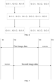
- FIG. 7 is a schematic diagram of a process for removing useless data in the present invention.
- the first sensor and the second sensor simultaneously perform image acquisition, and in the scanning device, the first sensor first scans the front-side data of the to-be-scanned document, so that the first image data collected by the first sensor at the time point T1 is the front-side data of the to-be-scanned document.
- the to-be-scanned document has not reached the second sensor, thus, the second image data collected by the second sensor at the time point T1 is useless data.
- the to-be-scanned document reaches the second sensor, the second image data collected by the second sensor beginning from the time point T2 is the reverse-sided data of the to-be-scanned document.
- the to-be-scanned document leaves the first sensor, and the first image data collected by the first sensor after the time point T3 is useless data.
- the to-be-scanned document leaves the second sensor, the first sensor and the second sensor stop the acquisition of the image data.
- xxxxx represents useless data, and the useless data needs to be removed.
- a second type one or more pixels of the first image data at the end of the first image-data series is deleted according to the first specified value, and one or more pixels of the second image data at the start of the second image-data series is deleted according to the second specified value.
- the first specified value and the second specified value may be preset according to actual needs, and the present invention does not specifically limit this.
- the acquired first image-data series and the second image-data series are stored separately.
- the scanning device may further include at least one memory.
- the first image-data series and the second image-data series may be separately stored by two memories, that is, the first image-data series are stored by a first memory, and the second image-data series are stored by a second memory.
- FIG. 8 is a schematic diagram of storing a first image-data series and a second image-data series in the present invention.
- the first image-data series acquired by the data remapping unit 206 are: R-1-1, G-1-1, and B-1-1; the acquired second image-data series are: R-2-1, G-2-1, and B-2-1.
- the first image-data series may be stored by the first memory on the left side in FIG. 8
- the second image-data series may be stored by the second memory on the right side in FIG. 8 to acquire the separately stored first image-data series and the first two image-data series.
- first image-data series and the second image-data series separately by two memories is only a specific implementation manner and is only used to indicate how to separately store the acquired first image-data series and second image-data series and is not intended to limit the present invention.
- the first image-data series and the second image-data series may be separately stored in different locations through a memory to acquire the separately stored first image-data series and second image-data series.
- the specific implementation of the present invention for separately storing the first image-data series and the second image-data series is not particularly limited.
- the acquired first image-data series and the second image-data series may further perform image processing, such as image edge sharpening processing, background removal processing, etc., and the first image-data series and the second image-data series after processed can be stored, which is not limited by the present invention.
- the scanning device in the existing technology includes two sensors and an image acquiring unit, where the two sensors respectively collect the front-side image data and the back-side image data of the to-be-scanned document, so as to acquire the image data collected by the two sensors through an image acquisition unit using an alternate line-by-line manner. Therefore, the scanning device must acquire the data collected by the other sensor after acquiring one line of data of one sensor. Therefore, when the scanning device is used for double-sided scanning of the to-be-scanned document, the scanning speed is half of the scanning speed of a single-sided scanning, the scanning time is long, and the scanning efficiency is low.
- the selector in the present invention acquires image data alternately from the first channel 203 and the second channel 204 by the pixel-by-pixel acquisition mode.
- the selector 205 may acquire a second image-data pixel output by the second sensor 202 by using a time interval after the first sensor 201 outputs a first image-data pixel, acquire a first image-data pixel output by the first sensor 201 by using the time interval after the first sensor 202 outputs a second image-data pixel.
- the length of the data that the selector 205 can collect in one acquisition cycle is smaller than the data length output by the sensors, so that the selector 205 can uninterruptedly and continuously acquire the image data collected by the first sensor 201 and the image data collected by the second sensor 202 alternately.
- the scanning speed of the double-sided scanning is the same as the scanning speed of the single-sided scanning, which greatly saves the scanning time and improves the scanning efficiency.
- the image-forming device 92 is configured to form an image on the image-forming medium based on the image data processed by the scanning device 91.
- the process of performing double-sided scanning by the scanning device shown in FIG. 9(b) is: after the to-be-scanned document passes through the paper feeding port 901, the paper-pickup roller assembly 909 transports the to-be-scanned document along the predetermined paper path in the A/DF to pass through the first sensor 904 and the second sensor 906.
- the first sensor 904 and the second sensor 906 respectively collect the first image data and the second image data of the to-be-scanned document. After the first sensor 904 collects the first image data and the second sensor 906 collects the second image data, after the completing scanning, the to-be-scanned document is discharged to the paper-discharge tray through the paper-discharge roller assembly 905.
- a sensor control unit 1011 is configured to send control signal such as clock control signal, lighting control signal, etc., to the first sensor 1006 and the second sensor 1007.
- the scanning device is also configured with a register bus 1003 connected to the scanning interface 1010.
- the CPU1002 of the scanning device is connected to the scanning interface 1010 through the register bus 1003.
- the CPU1002 can share data with external memory and the USB interface, etc. though the data bus 1001.
- the CPU1002 can send control instruction to the motor controller 1004 though the register bus 1003.
- the motor controller 1004 can send clock signal to the motor 1005 according to the received control instruction.
- the scanning interface 1010, the data acquisition unit 1020, the register bus 1003, and the CPU 1002 and the data bus 1001 in the dashed-line frame in FIG. 10 can be integrated into one controller, so there is no need to add additional image acquisition unit hardware circuit, reducing the cost.
- the image-forming apparatus acquires images by scanning the document simultaneously by two sensors, and processes the images collected by the two sensors through a selector, thereby saving hardware costs and solving the problems of high hardware costs of the scanning device to realize double-sided scanning device.
- FIG. 11 is a schematic flowchart of a scanning method provided by the present invention. As shown in FIG. 11 , the method includes:
- the method further includes: the data remapping unit remapping the acquired image data according to an acquisition sequence of the selector, to acquire a first image-data series and a second-image-data series, where the first image-data series includes the first image data arranged in the acquisition sequence of the selector, and the second image-data series includes the second image data arranged in the acquisition sequence of the selector.
- the scanning method provided by the present invention acquires images by scanning the document simultaneously by two sensors, and processes the images collected by the two sensors through a selector, thereby saving hardware costs and solving the problems of high hardware costs of the scanning device to realize double-sided scanning device.
- the disclosed system, apparatus, and method may be implemented in other manners.
- the device embodiments described above are merely illustrative.
- the division of the unit is only a logical function division, and the actual implementation may have another division manner.
- multiple units or components may be combined or it can be integrated into another system, or some features can be ignored or not executed.
- the coupling or direct coupling or communication connection shown or discussed herein may be an indirect coupling or communication connection through some interface, device or unit, and may be electrical, mechanical or other forms.
- the units described as separate components may or may not be physically separated, and the components displayed as units may or may not be physical units, that is, may be located in one place, or may be distributed to multiple network units. Some or all of the units may be selected according to actual needs to achieve the purpose of the solution of the embodiment.
- each functional unit in each embodiment of the present invention may be integrated into one processing unit, or each unit may exist physically separately, or two or more units may be integrated into one unit.
- the above integrated unit can be implemented in the form of hardware or in the form of hardware and software functional units.
- the above-described integrated unit implemented in the form of a software functional unit can be stored in a computer readable storage medium.
- the software functional unit described above is stored in a storage medium and includes instructions for causing a computer device (which may be a personal computer, a server, or a network device, etc.) or a processor to perform partial steps of the methods of the various embodiments of the present invention.
- the foregoing storage medium may be various medium can store program codes including: a U disk, a mobile hard disk, a read-only memory (ROM), a random access memory (RAM), a magnetic disk, or an optical disk, etc., which can store program codes.
Landscapes
- Engineering & Computer Science (AREA)
- Multimedia (AREA)
- Signal Processing (AREA)
- Environmental & Geological Engineering (AREA)
- Facsimile Scanning Arrangements (AREA)
- Image Input (AREA)
Claims (13)
- Eine Abtastvorrichtung (91), umfassend: einen ersten Sensor (201), einen zweiten Sensor (202), einen ersten Kanal (203), der dem ersten Sensor entspricht, einen zweiten Kanal (204), der dem zweiten Sensor entspricht, und einen Selektor (205);der erste Sensor, der konfiguriert ist, um erste Bilddaten eines zu scannenden Dokuments zu erfassen;der zweite Sensor, der konfiguriert ist, um zweite Bilddaten des zu scannenden Dokuments zu erfassen; undder Selektor ist konfiguriert, um die von dem ersten Sensor erfassten Bilddaten und die von dem zweiten Sensor erfassten Bilddaten in einer ununterbrochenen, kontinuierlichen und überkreuzten Flussweise zu erfassen;der Selektor ist konfiguriert, um Bilddaten abwechselnd aus dem ersten Kanal und dem zweiten Kanal zu erfassen, um erste Bilddaten aus dem ersten Kanal und zweite Bilddaten aus dem zweiten Kanal mittels eines pixelweisen Erfassungsmodus in einem Erfassungszyklus zu gewinnen;dadurch gekennzeichnet, dass eine Auswahlfrequenz des Selektors zur Auswahl des ersten Kanals oder des zweiten Kanals größer oder gleich dem Zweifachen einer Ausgangsfrequenz des ersten Sensors ist; und/oder die Auswahlfrequenz des Selektors zur Auswahl des ersten Kanals oder des zweiten Kanals größer oder gleich dem Zweifachen einer Ausgangsfrequenz des zweiten Sensors ist.
- Die Abtastvorrichtung nach Anspruch 1, wobei die Abtastvorrichtung ferner eine Datenzuordnungseinheit (206) umfasst;
die Datenzuordnungseinheit ist konfiguriert, um die von dem ersten Sensor und dem zweiten Sensor erfassten Bilddaten gemäß einer Erfassungssequenz des Selektors neu zuzuordnen, um eine erste Bilddatensequenz und eine zweite Bilddatensequenz zu erhalten; die erste Bilddatensequenz umfasst die ersten Bilddaten, die gemäß der Erfassungssequenz des Selektors angeordnet sind, und die zweite Bilddatensequenz umfasst die zweiten Bilddaten, die gemäß der Erfassungssequenz des Selektors angeordnet sind. - Die Abtastvorrichtung nach Anspruch 2, wobei die Abtastvorrichtung ferner einen ersten Wandler (207) umfasst, der zwischen dem Selektor und der Datenzuordnungseinheit angeordnet ist;der erste Wandler ist konfiguriert, um eine Analog-Digital-Umwandlung der von dem Selektor erfassten Bilddaten durchzuführen; undder erste Wandler ist ferner konfiguriert, um die durch die Analog-Digital-Umwandlung gewonnenen Bilddaten entsprechend der Erfassungssequenz des Selektors an die Datenzuordnungseinheit zu senden.
- Die Abtastvorrichtung nach Anspruch 2, wobei die Abtastvorrichtung ferner einen zweiten Wandler (208) umfasst, der zwischen dem ersten Sensor und dem ersten Kanal angeordnet ist, sowie einen dritten Wandler (209), der zwischen dem zweiten Sensor und dem zweiten Kanal angeordnet ist;der zweite Wandler ist konfiguriert, um eine Analog-Digital-Umwandlung der von dem ersten Sensor erfassten ersten Bilddaten durchzuführen; undder dritte Wandler ist konfiguriert, um eine Analog-Digital-Umwandlung der von dem zweiten Sensor erfassten zweiten Bilddaten durchzuführen.
- Die Abtastvorrichtung nach Anspruch 2, wobei die Abtastvorrichtung ferner eine Datenfiltereinheit (210) umfasst, die konfiguriert ist, um:einen ersten Zeitpunkt und einen zweiten Zeitpunkt zu bestimmen; undein oder mehrere Pixel der ersten Bilddaten in der ersten Bilddatensequenz, die von dem ersten Sensor nach dem ersten Zeitpunkt erfasst wurden, zu löschen, sowie ein oder mehrere Pixel der zweiten Bilddaten in der zweiten Bilddatensequenz, die von dem zweiten Sensor vor dem zweiten Zeitpunkt erfasst wurden, zu löschen; oderein oder mehrere Pixel der ersten Bilddaten am Ende der ersten Bilddatensequenz gemäß einem ersten spezifizierten Wert zu löschen und ein oder mehrere Pixel der zweiten Bilddaten am Anfang der zweiten Bilddatensequenz gemäß einem zweiten spezifizierten Wert zu löschen.
- Die Abtastvorrichtung nach einem der Ansprüche 1 bis 5, wobeidie ersten Bilddaten Bilddaten der Vorderseite des zu scannenden Dokuments sind, und die zweiten Bilddaten Bilddaten der Rückseite des zu scannenden Dokuments sind; oderdie ersten Bilddaten und die zweiten Bilddaten Bilddaten der Vorderseite des zu scannenden Dokuments sind; oderdie ersten Bilddaten und die zweiten Bilddaten Bilddaten der Rückseite des zu scannenden Dokuments sind.
- Eine Bilderzeugungsvorrichtung, wobei die Vorrichtung die Abtastvorrichtung nach einem der Ansprüche 1 bis 6 und eine Bilderzeugungseinrichtung (92) umfasst; und
die Bilderzeugungseinrichtung ist konfiguriert, um ein Bild auf einem Bilderzeugungsmedium gemäß den von der Abtastvorrichtung verarbeiteten Bilddaten zu erzeugen. - Ein Abtastverfahren, umfassend:das Erfassen erster Bilddaten eines zu scannenden Dokuments durch einen ersten Sensor (201);das Erfassen zweiter Bilddaten des zu scannenden Dokuments durch einen zweiten Sensor (202);die Verwendung eines Selektors (205) im pixelweisen Erfassungsmodus zur alternierenden Erfassung von Bilddaten aus einem ersten Kanal (203) und einem zweiten Kanal (204), um in einem Erfassungszyklus erste Bilddaten aus dem ersten Kanal und zweite Bilddaten aus dem zweiten Kanal zu gewinnen, wobei der Selektor die von dem ersten Sensor erfassten Bilddaten und die von dem zweiten Sensor erfassten Bilddaten in einer ununterbrochenen, kontinuierlichen und überkreuzten Flussweise erfasst,dadurch gekennzeichnet, dasseine Auswahlfrequenz des Selektors zur Auswahl des ersten Kanals oder des zweiten Kanals größer oder gleich dem Zweifachen einer Ausgangsfrequenz des ersten Sensors ist; und/oder die Auswahlfrequenz, wenn der Selektor den ersten Kanal oder den zweiten Kanal auswählt, größer oder gleich dem Zweifachen einer Ausgangsfrequenz des zweiten Sensors ist.
- Das Verfahren nach Anspruch 8, wobei das Verfahren ferner umfasst:
die Neuordnung der erfassten Bilddaten gemäß einer Erfassungssequenz des Selektors durch eine Datenzuordnungseinheit (206), um eine erste Bilddatensequenz und eine zweite Bilddatensequenz zu erhalten, wobei die erste Bilddatensequenz die ersten Bilddaten umfasst, die in der Erfassungssequenz des Selektors angeordnet sind, und die zweite Bilddatensequenz die zweiten Bilddaten umfasst, die in der Erfassungssequenz des Selektors angeordnet sind. - Das Verfahren nach Anspruch 9, wobei vor der Neuordnung der erfassten Bilddaten durch die Datenzuordnungseinheit gemäß der Erfassungssequenz des Selektors das Verfahren ferner umfasst:
die Durchführung einer Analog-Digital-Umwandlung der von dem ersten Sensor und dem zweiten Sensor erfassten Bilddaten durch einen ersten Wandler (207) und die Übermittlung der durch die Analog-Digital-Umwandlung gewonnenen Bilddaten an die Datenzuordnungseinheit gemäß der Erfassungssequenz des Selektors. - Das Verfahren nach Anspruch 9, wobei vor der alternierenden Erfassung der Bilddaten aus dem ersten Kanal und dem zweiten Kanal durch den pixelweisen Erfassungsmodus das Verfahren ferner umfasst:die Durchführung einer Analog-Digital-Umwandlung der von dem ersten Sensor erfassten ersten Bilddaten durch einen zweiten Wandler (208); unddie Durchführung einer Analog-Digital-Umwandlung der von dem zweiten Sensor erfassten zweiten Bilddaten durch einen dritten Wandler (209).
- Das Verfahren nach Anspruch 9, wobei nach der Neuordnung der erfassten Bilddaten gemäß der Erfassungssequenz des Selektors zur Gewinnung der ersten Bilddatensequenz und der zweiten Bilddatensequenz das Verfahren ferner umfasst:das Bestimmen eines ersten Zeitpunkts und eines zweiten Zeitpunkts durch eine Datenfiltereinheit (210); und das Löschen eines oder mehrerer Pixel der ersten Bilddaten in der ersten Bilddatensequenz, die von dem ersten Sensor nach dem ersten Zeitpunkt erfasst wurden, sowie das Löschen eines oder mehrerer Pixel der zweiten Bilddaten in der zweiten Bilddatensequenz, die von dem zweiten Sensor vor dem zweiten Zeitpunkt erfasst wurden, durch die Datenfiltereinheit; oderdas Löschen eines oder mehrerer Pixel der ersten Bilddaten am Ende der ersten Bilddatensequenz gemäß einem ersten spezifizierten Wert und das Löschen eines oder mehrerer Pixel der zweiten Bilddaten am Anfang der zweiten Bilddatensequenz gemäß einem zweiten spezifizierten Wert durch die Datenfiltereinheit.
- Das Verfahren nach einem der Ansprüche 8 bis 12, wobeidie ersten Bilddaten Bilddaten der Vorderseite des zu scannenden Dokuments sind, und die zweiten Bilddaten Bilddaten der Rückseite des zu scannenden Dokuments sind; oderdie ersten Bilddaten und die zweiten Bilddaten Bilddaten der Vorderseite des zu scannenden Dokuments sind; oderdie ersten Bilddaten und die zweiten Bilddaten Bilddaten der Rückseite des zu scannenden Dokuments sind.
Applications Claiming Priority (2)
| Application Number | Priority Date | Filing Date | Title |
|---|---|---|---|
| CN201610736117.5A CN106357949B (zh) | 2016-08-26 | 2016-08-26 | 一种扫描装置、图像形成设备和扫描方法 |
| PCT/CN2017/093524 WO2018036308A1 (zh) | 2016-08-26 | 2017-07-19 | 一种扫描装置、图像形成设备和扫描方法 |
Publications (4)
| Publication Number | Publication Date |
|---|---|
| EP3490236A1 EP3490236A1 (de) | 2019-05-29 |
| EP3490236A4 EP3490236A4 (de) | 2019-07-03 |
| EP3490236C0 EP3490236C0 (de) | 2025-03-26 |
| EP3490236B1 true EP3490236B1 (de) | 2025-03-26 |
Family
ID=57855095
Family Applications (1)
| Application Number | Title | Priority Date | Filing Date |
|---|---|---|---|
| EP17842731.6A Active EP3490236B1 (de) | 2016-08-26 | 2017-07-19 | Abtastvorrichtung, bildgebungsvorrichtung und abtastverfahren |
Country Status (5)
| Country | Link |
|---|---|
| US (1) | US10477060B2 (de) |
| EP (1) | EP3490236B1 (de) |
| CN (1) | CN106357949B (de) |
| RU (1) | RU2735942C2 (de) |
| WO (1) | WO2018036308A1 (de) |
Families Citing this family (5)
| Publication number | Priority date | Publication date | Assignee | Title |
|---|---|---|---|---|
| CN106357949B (zh) | 2016-08-26 | 2019-08-06 | 珠海赛纳打印科技股份有限公司 | 一种扫描装置、图像形成设备和扫描方法 |
| CN110233948B (zh) * | 2019-07-15 | 2024-10-29 | 珠海奔图电子有限公司 | 扫描设备、图像形成装置、扫描方法及存储介质 |
| CN112100424B (zh) * | 2020-08-28 | 2024-06-18 | 中保车服科技服务股份有限公司 | 证件图像分类采集方法、装置、设备和介质 |
| JP7513954B2 (ja) * | 2020-10-16 | 2024-07-10 | セイコーエプソン株式会社 | 画像読取装置 |
| CN120499521B (zh) * | 2025-07-15 | 2025-09-23 | 杭州海康微影传感科技有限公司 | 一种图像数据传输方法、装置及设备 |
Family Cites Families (26)
| Publication number | Priority date | Publication date | Assignee | Title |
|---|---|---|---|---|
| US4908719A (en) * | 1987-12-26 | 1990-03-13 | Kabushiki Kaisha Toshiba | Scanning apparatus with a mechanism to scan both sides of an original |
| US5280545A (en) * | 1988-12-29 | 1994-01-18 | Canon Kabushiki Kaisha | Image information processing apparatus capable of synthesizing front- and back-surface information |
| JP2821161B2 (ja) * | 1989-03-07 | 1998-11-05 | キヤノン株式会社 | 画像情報処理装置 |
| US5023711A (en) * | 1989-10-16 | 1991-06-11 | Eastman Kodak Company | Line scanning apparatus using staggered linear segments with adjoining overlap regions |
| JP3428764B2 (ja) * | 1995-03-03 | 2003-07-22 | キヤノン株式会社 | 信号処理装置 |
| US5760919A (en) * | 1995-12-01 | 1998-06-02 | Xerox Corporation | Duplex documents scanner with alternating scan lines from dual imaging stations |
| DE19605938B4 (de) * | 1996-02-17 | 2004-09-16 | Fachhochschule Wiesbaden | Bildabtaster |
| JP3353220B2 (ja) * | 1996-03-25 | 2002-12-03 | ミノルタ株式会社 | 画像処理装置 |
| US6075622A (en) * | 1997-10-14 | 2000-06-13 | Eastman Kodak Company | Duplex document scanner for processing multiplexed images with a single data path |
| US6160578A (en) * | 1998-06-18 | 2000-12-12 | Redlake Imaging Corporation | High speed, increased bandwidth camera |
| US6512546B1 (en) * | 1998-07-17 | 2003-01-28 | Analog Devices, Inc. | Image sensor using multiple array readout lines |
| CN1395217A (zh) * | 2001-07-06 | 2003-02-05 | 力捷电脑股份有限公司 | 一步两曝光的扫描方法 |
| CN1614985A (zh) * | 2003-11-07 | 2005-05-11 | 虹光精密工业(苏州)有限公司 | 图像撷取装置及其方法 |
| US7394632B2 (en) * | 2004-09-30 | 2008-07-01 | Rockwell Automation Technologies, Inc. | Line interface module |
| US8929688B2 (en) * | 2004-10-01 | 2015-01-06 | University Of Washington | Remapping methods to reduce distortions in images |
| CN100397860C (zh) * | 2004-12-13 | 2008-06-25 | 崴强科技股份有限公司 | 影像信号合成模组及方法 |
| CN100496081C (zh) * | 2005-02-03 | 2009-06-03 | 虹光精密工业(苏州)有限公司 | 双面扫描装置 |
| JP4636246B2 (ja) * | 2005-06-30 | 2011-02-23 | ブラザー工業株式会社 | 画像読取装置 |
| JP4692115B2 (ja) * | 2005-07-11 | 2011-06-01 | ソニー株式会社 | 画像処理装置および撮像装置 |
| JP5084677B2 (ja) * | 2008-09-12 | 2012-11-28 | キヤノン株式会社 | 原稿サイズ検知装置 |
| TWI389548B (zh) * | 2008-11-14 | 2013-03-11 | Genesys Logic Inc | 雙面文件掃描系統及其方法 |
| JP5532992B2 (ja) * | 2010-02-10 | 2014-06-25 | セイコーエプソン株式会社 | 書画カメラ、書画カメラの制御方法およびプログラム |
| US9143696B2 (en) * | 2012-10-13 | 2015-09-22 | Hewlett-Packard Development Company, L.P. | Imaging using offsetting accumulations |
| JP6324176B2 (ja) * | 2014-04-07 | 2018-05-16 | キヤノン株式会社 | 画像読取装置、制御方法、プログラム、システム |
| CN104104825B (zh) * | 2014-07-03 | 2017-03-29 | 宁波术有电子科技有限公司 | 基于fpga的双面扫描仪采集系统的校正方法 |
| CN106357949B (zh) * | 2016-08-26 | 2019-08-06 | 珠海赛纳打印科技股份有限公司 | 一种扫描装置、图像形成设备和扫描方法 |
-
2016
- 2016-08-26 CN CN201610736117.5A patent/CN106357949B/zh active Active
-
2017
- 2017-07-19 RU RU2019103342A patent/RU2735942C2/ru active
- 2017-07-19 EP EP17842731.6A patent/EP3490236B1/de active Active
- 2017-07-19 WO PCT/CN2017/093524 patent/WO2018036308A1/zh not_active Ceased
-
2019
- 2019-02-15 US US16/276,989 patent/US10477060B2/en active Active
Also Published As
| Publication number | Publication date |
|---|---|
| EP3490236A1 (de) | 2019-05-29 |
| EP3490236A4 (de) | 2019-07-03 |
| CN106357949A (zh) | 2017-01-25 |
| WO2018036308A1 (zh) | 2018-03-01 |
| CN106357949B (zh) | 2019-08-06 |
| EP3490236C0 (de) | 2025-03-26 |
| US20190182403A1 (en) | 2019-06-13 |
| RU2019103342A (ru) | 2020-09-28 |
| RU2019103342A3 (de) | 2020-09-28 |
| US10477060B2 (en) | 2019-11-12 |
| RU2735942C2 (ru) | 2020-11-11 |
Similar Documents
| Publication | Publication Date | Title |
|---|---|---|
| US10477060B2 (en) | Scanning device, image-forming apparatus, and scanning method | |
| JP6103918B2 (ja) | 画像処理装置および画像処理方法 | |
| CN102196134B (zh) | 图像处理设备及图像处理方法 | |
| CN101355619B (zh) | 成像设备以及控制该成像设备的方法 | |
| US6236759B1 (en) | Image processing apparatus | |
| CN210640937U (zh) | 扫描设备及图像形成装置 | |
| US7710613B2 (en) | Image information apparatus | |
| US10200559B2 (en) | Image scanning apparatus with two-sided scanning, control method therefor, and multifunction apparatus | |
| JP2011077875A (ja) | 画像読取装置及びプログラム | |
| EP2180689B1 (de) | Dokumentenlesevorrichtung | |
| US20130176591A1 (en) | Signal processing circuit, image processing apparatus, and signal processing method | |
| CN112600988B (zh) | 图像形成装置及扫描方法 | |
| US7522321B2 (en) | Image capturing apparatus and method | |
| US8792144B2 (en) | Image reading device and image reading method | |
| JP2007013742A (ja) | 画像読取装置 | |
| JP2009060463A (ja) | 画像読取装置 | |
| JPH09205524A (ja) | ファクシミリ装置 | |
| JP3596839B2 (ja) | ファクシミリ機能付ディジタル複写機 | |
| JP3224385B2 (ja) | 画像処理装置 | |
| JP4977672B2 (ja) | 網点検出回路、及びこれを備えた画像処理装置 | |
| JP2016116171A (ja) | 画像処理装置、制御方法およびプログラム | |
| JP2010183367A (ja) | 画像読取システムおよび画像読取装置 | |
| JP6179144B2 (ja) | 画像処理装置及び画像形成装置 | |
| JPH09200462A (ja) | 画像信号分割装置 | |
| JP2003320716A (ja) | 印刷装置 |
Legal Events
| Date | Code | Title | Description |
|---|---|---|---|
| STAA | Information on the status of an ep patent application or granted ep patent |
Free format text: STATUS: THE INTERNATIONAL PUBLICATION HAS BEEN MADE |
|
| PUAI | Public reference made under article 153(3) epc to a published international application that has entered the european phase |
Free format text: ORIGINAL CODE: 0009012 |
|
| STAA | Information on the status of an ep patent application or granted ep patent |
Free format text: STATUS: REQUEST FOR EXAMINATION WAS MADE |
|
| 17P | Request for examination filed |
Effective date: 20190219 |
|
| AK | Designated contracting states |
Kind code of ref document: A1 Designated state(s): AL AT BE BG CH CY CZ DE DK EE ES FI FR GB GR HR HU IE IS IT LI LT LU LV MC MK MT NL NO PL PT RO RS SE SI SK SM TR |
|
| AX | Request for extension of the european patent |
Extension state: BA ME |
|
| A4 | Supplementary search report drawn up and despatched |
Effective date: 20190531 |
|
| RIC1 | Information provided on ipc code assigned before grant |
Ipc: H04N 1/203 20060101ALI20190524BHEP Ipc: H04N 1/00 20060101AFI20190524BHEP Ipc: H04N 1/024 20060101ALI20190524BHEP Ipc: H04N 1/04 20060101ALI20190524BHEP |
|
| DAV | Request for validation of the european patent (deleted) | ||
| DAX | Request for extension of the european patent (deleted) | ||
| STAA | Information on the status of an ep patent application or granted ep patent |
Free format text: STATUS: EXAMINATION IS IN PROGRESS |
|
| 17Q | First examination report despatched |
Effective date: 20210604 |
|
| GRAP | Despatch of communication of intention to grant a patent |
Free format text: ORIGINAL CODE: EPIDOSNIGR1 |
|
| STAA | Information on the status of an ep patent application or granted ep patent |
Free format text: STATUS: GRANT OF PATENT IS INTENDED |
|
| INTG | Intention to grant announced |
Effective date: 20241107 |
|
| GRAS | Grant fee paid |
Free format text: ORIGINAL CODE: EPIDOSNIGR3 |
|
| GRAA | (expected) grant |
Free format text: ORIGINAL CODE: 0009210 |
|
| STAA | Information on the status of an ep patent application or granted ep patent |
Free format text: STATUS: THE PATENT HAS BEEN GRANTED |
|
| AK | Designated contracting states |
Kind code of ref document: B1 Designated state(s): AL AT BE BG CH CY CZ DE DK EE ES FI FR GB GR HR HU IE IS IT LI LT LU LV MC MK MT NL NO PL PT RO RS SE SI SK SM TR |
|
| REG | Reference to a national code |
Ref country code: GB Ref legal event code: FG4D |
|
| REG | Reference to a national code |
Ref country code: CH Ref legal event code: EP |
|
| REG | Reference to a national code |
Ref country code: DE Ref legal event code: R096 Ref document number: 602017088573 Country of ref document: DE |
|
| REG | Reference to a national code |
Ref country code: IE Ref legal event code: FG4D |
|
| U01 | Request for unitary effect filed |
Effective date: 20250421 |
|
| U07 | Unitary effect registered |
Designated state(s): AT BE BG DE DK EE FI FR IT LT LU LV MT NL PT RO SE SI Effective date: 20250428 |
|
| PG25 | Lapsed in a contracting state [announced via postgrant information from national office to epo] |
Ref country code: RS Free format text: LAPSE BECAUSE OF FAILURE TO SUBMIT A TRANSLATION OF THE DESCRIPTION OR TO PAY THE FEE WITHIN THE PRESCRIBED TIME-LIMIT Effective date: 20250626 |
|
| PG25 | Lapsed in a contracting state [announced via postgrant information from national office to epo] |
Ref country code: NO Free format text: LAPSE BECAUSE OF FAILURE TO SUBMIT A TRANSLATION OF THE DESCRIPTION OR TO PAY THE FEE WITHIN THE PRESCRIBED TIME-LIMIT Effective date: 20250626 |
|
| PG25 | Lapsed in a contracting state [announced via postgrant information from national office to epo] |
Ref country code: HR Free format text: LAPSE BECAUSE OF FAILURE TO SUBMIT A TRANSLATION OF THE DESCRIPTION OR TO PAY THE FEE WITHIN THE PRESCRIBED TIME-LIMIT Effective date: 20250326 |
|
| PG25 | Lapsed in a contracting state [announced via postgrant information from national office to epo] |
Ref country code: GR Free format text: LAPSE BECAUSE OF FAILURE TO SUBMIT A TRANSLATION OF THE DESCRIPTION OR TO PAY THE FEE WITHIN THE PRESCRIBED TIME-LIMIT Effective date: 20250627 |
|
| U20 | Renewal fee for the european patent with unitary effect paid |
Year of fee payment: 9 Effective date: 20250728 |
|
| PG25 | Lapsed in a contracting state [announced via postgrant information from national office to epo] |
Ref country code: SM Free format text: LAPSE BECAUSE OF FAILURE TO SUBMIT A TRANSLATION OF THE DESCRIPTION OR TO PAY THE FEE WITHIN THE PRESCRIBED TIME-LIMIT Effective date: 20250326 |
|
| PG25 | Lapsed in a contracting state [announced via postgrant information from national office to epo] |
Ref country code: ES Free format text: LAPSE BECAUSE OF FAILURE TO SUBMIT A TRANSLATION OF THE DESCRIPTION OR TO PAY THE FEE WITHIN THE PRESCRIBED TIME-LIMIT Effective date: 20250326 |
|
| PG25 | Lapsed in a contracting state [announced via postgrant information from national office to epo] |
Ref country code: PL Free format text: LAPSE BECAUSE OF FAILURE TO SUBMIT A TRANSLATION OF THE DESCRIPTION OR TO PAY THE FEE WITHIN THE PRESCRIBED TIME-LIMIT Effective date: 20250326 |
|
| PG25 | Lapsed in a contracting state [announced via postgrant information from national office to epo] |
Ref country code: SK Free format text: LAPSE BECAUSE OF FAILURE TO SUBMIT A TRANSLATION OF THE DESCRIPTION OR TO PAY THE FEE WITHIN THE PRESCRIBED TIME-LIMIT Effective date: 20250326 |
|
| PG25 | Lapsed in a contracting state [announced via postgrant information from national office to epo] |
Ref country code: IS Free format text: LAPSE BECAUSE OF FAILURE TO SUBMIT A TRANSLATION OF THE DESCRIPTION OR TO PAY THE FEE WITHIN THE PRESCRIBED TIME-LIMIT Effective date: 20250726 |
|
| PG25 | Lapsed in a contracting state [announced via postgrant information from national office to epo] |
Ref country code: CZ Free format text: LAPSE BECAUSE OF FAILURE TO SUBMIT A TRANSLATION OF THE DESCRIPTION OR TO PAY THE FEE WITHIN THE PRESCRIBED TIME-LIMIT Effective date: 20250326 |
|
| PLBE | No opposition filed within time limit |
Free format text: ORIGINAL CODE: 0009261 |
|
| STAA | Information on the status of an ep patent application or granted ep patent |
Free format text: STATUS: NO OPPOSITION FILED WITHIN TIME LIMIT |
|
| REG | Reference to a national code |
Ref country code: CH Ref legal event code: L10 Free format text: ST27 STATUS EVENT CODE: U-0-0-L10-L00 (AS PROVIDED BY THE NATIONAL OFFICE) Effective date: 20260211 |