EP3489447B1 - Door entrapment detector and door opening-closing device - Google Patents
Door entrapment detector and door opening-closing device Download PDFInfo
- Publication number
- EP3489447B1 EP3489447B1 EP18207192.8A EP18207192A EP3489447B1 EP 3489447 B1 EP3489447 B1 EP 3489447B1 EP 18207192 A EP18207192 A EP 18207192A EP 3489447 B1 EP3489447 B1 EP 3489447B1
- Authority
- EP
- European Patent Office
- Prior art keywords
- door
- vehicle
- entrapment
- threshold value
- detection signal
- Prior art date
- Legal status (The legal status is an assumption and is not a legal conclusion. Google has not performed a legal analysis and makes no representation as to the accuracy of the status listed.)
- Active
Links
- 238000001514 detection method Methods 0.000 claims description 211
- 230000007274 generation of a signal involved in cell-cell signaling Effects 0.000 claims description 43
- 238000000034 method Methods 0.000 claims description 33
- 230000008569 process Effects 0.000 claims description 33
- 230000000694 effects Effects 0.000 claims description 10
- 230000008901 benefit Effects 0.000 description 10
- 238000010586 diagram Methods 0.000 description 5
- 230000009467 reduction Effects 0.000 description 4
- 230000007423 decrease Effects 0.000 description 3
- 230000004913 activation Effects 0.000 description 2
- 230000009849 deactivation Effects 0.000 description 2
- 239000013013 elastic material Substances 0.000 description 2
- 230000008859 change Effects 0.000 description 1
- 230000003247 decreasing effect Effects 0.000 description 1
- 238000001914 filtration Methods 0.000 description 1
- 230000035945 sensitivity Effects 0.000 description 1
- 230000001960 triggered effect Effects 0.000 description 1
Images


Classifications
-
- E—FIXED CONSTRUCTIONS
- E05—LOCKS; KEYS; WINDOW OR DOOR FITTINGS; SAFES
- E05F—DEVICES FOR MOVING WINGS INTO OPEN OR CLOSED POSITION; CHECKS FOR WINGS; WING FITTINGS NOT OTHERWISE PROVIDED FOR, CONCERNED WITH THE FUNCTIONING OF THE WING
- E05F15/00—Power-operated mechanisms for wings
- E05F15/40—Safety devices, e.g. detection of obstructions or end positions
- E05F15/42—Detection using safety edges
- E05F15/47—Detection using safety edges responsive to changes in fluid pressure
-
- E—FIXED CONSTRUCTIONS
- E05—LOCKS; KEYS; WINDOW OR DOOR FITTINGS; SAFES
- E05Y—INDEXING SCHEME ASSOCIATED WITH SUBCLASSES E05D AND E05F, RELATING TO CONSTRUCTION ELEMENTS, ELECTRIC CONTROL, POWER SUPPLY, POWER SIGNAL OR TRANSMISSION, USER INTERFACES, MOUNTING OR COUPLING, DETAILS, ACCESSORIES, AUXILIARY OPERATIONS NOT OTHERWISE PROVIDED FOR, APPLICATION THEREOF
- E05Y2400/00—Electronic control; Electrical power; Power supply; Power or signal transmission; User interfaces
- E05Y2400/10—Electronic control
- E05Y2400/44—Sensors not directly associated with the wing movement
-
- E—FIXED CONSTRUCTIONS
- E05—LOCKS; KEYS; WINDOW OR DOOR FITTINGS; SAFES
- E05Y—INDEXING SCHEME ASSOCIATED WITH SUBCLASSES E05D AND E05F, RELATING TO CONSTRUCTION ELEMENTS, ELECTRIC CONTROL, POWER SUPPLY, POWER SIGNAL OR TRANSMISSION, USER INTERFACES, MOUNTING OR COUPLING, DETAILS, ACCESSORIES, AUXILIARY OPERATIONS NOT OTHERWISE PROVIDED FOR, APPLICATION THEREOF
- E05Y2400/00—Electronic control; Electrical power; Power supply; Power or signal transmission; User interfaces
- E05Y2400/10—Electronic control
- E05Y2400/50—Fault detection
- E05Y2400/508—Fault detection of detection
-
- E—FIXED CONSTRUCTIONS
- E05—LOCKS; KEYS; WINDOW OR DOOR FITTINGS; SAFES
- E05Y—INDEXING SCHEME ASSOCIATED WITH SUBCLASSES E05D AND E05F, RELATING TO CONSTRUCTION ELEMENTS, ELECTRIC CONTROL, POWER SUPPLY, POWER SIGNAL OR TRANSMISSION, USER INTERFACES, MOUNTING OR COUPLING, DETAILS, ACCESSORIES, AUXILIARY OPERATIONS NOT OTHERWISE PROVIDED FOR, APPLICATION THEREOF
- E05Y2400/00—Electronic control; Electrical power; Power supply; Power or signal transmission; User interfaces
- E05Y2400/10—Electronic control
- E05Y2400/52—Safety arrangements associated with the wing motor
- E05Y2400/53—Wing impact prevention or reduction
- E05Y2400/54—Obstruction or resistance detection
-
- E—FIXED CONSTRUCTIONS
- E05—LOCKS; KEYS; WINDOW OR DOOR FITTINGS; SAFES
- E05Y—INDEXING SCHEME ASSOCIATED WITH SUBCLASSES E05D AND E05F, RELATING TO CONSTRUCTION ELEMENTS, ELECTRIC CONTROL, POWER SUPPLY, POWER SIGNAL OR TRANSMISSION, USER INTERFACES, MOUNTING OR COUPLING, DETAILS, ACCESSORIES, AUXILIARY OPERATIONS NOT OTHERWISE PROVIDED FOR, APPLICATION THEREOF
- E05Y2900/00—Application of doors, windows, wings or fittings thereof
- E05Y2900/50—Application of doors, windows, wings or fittings thereof for vehicles
- E05Y2900/506—Application of doors, windows, wings or fittings thereof for vehicles for buses
-
- E—FIXED CONSTRUCTIONS
- E05—LOCKS; KEYS; WINDOW OR DOOR FITTINGS; SAFES
- E05Y—INDEXING SCHEME ASSOCIATED WITH SUBCLASSES E05D AND E05F, RELATING TO CONSTRUCTION ELEMENTS, ELECTRIC CONTROL, POWER SUPPLY, POWER SIGNAL OR TRANSMISSION, USER INTERFACES, MOUNTING OR COUPLING, DETAILS, ACCESSORIES, AUXILIARY OPERATIONS NOT OTHERWISE PROVIDED FOR, APPLICATION THEREOF
- E05Y2900/00—Application of doors, windows, wings or fittings thereof
- E05Y2900/50—Application of doors, windows, wings or fittings thereof for vehicles
- E05Y2900/51—Application of doors, windows, wings or fittings thereof for vehicles for railway cars or mass transit vehicles
-
- E—FIXED CONSTRUCTIONS
- E05—LOCKS; KEYS; WINDOW OR DOOR FITTINGS; SAFES
- E05Y—INDEXING SCHEME ASSOCIATED WITH SUBCLASSES E05D AND E05F, RELATING TO CONSTRUCTION ELEMENTS, ELECTRIC CONTROL, POWER SUPPLY, POWER SIGNAL OR TRANSMISSION, USER INTERFACES, MOUNTING OR COUPLING, DETAILS, ACCESSORIES, AUXILIARY OPERATIONS NOT OTHERWISE PROVIDED FOR, APPLICATION THEREOF
- E05Y2900/00—Application of doors, windows, wings or fittings thereof
- E05Y2900/50—Application of doors, windows, wings or fittings thereof for vehicles
- E05Y2900/53—Type of wing
- E05Y2900/531—Doors
Definitions
- the present invention relates to a door entrapment detector and a door opening-closing device for a door that opens and closes an entrance of a vehicle.
- WO 2004/090273 A1 describes a moving device and an open/close control device for a moving body.
- An object detecting means for detecting a contact of an object is provided on the moving body.
- a driving means drives the moving body and a control means controls the driving means.
- the control means stops the movement of the moving body or controls the driving means in such a manner as to reverse the moving direction of the moving body when the object detecting means detects a contact of an object or detects a removal of the object that has been in contact.
- a filter having a filtering property is provided to extract only a specific frequency component to an output signal of the object detecting means that is generated when the object detecting means is deformed by the contact with the object by removing unnecessary signals attributed to vibrations of the moving body from the output signal.
- a control device for an opening/closing body of a vehicle is known from US 7 646 158 B2 .
- This known control device comprises a pinching detecting means detecting pinching of an obstacle during an opening and closing operation of an opening/closing body.
- a control means stops the operation of the opening/closing body or actuates the opening/closing body in a reverse direction.
- the control means decreases the pinching detecting sensitivity of the pinching detecting means when the vehicle braking state is cancelled during the operation of the opening/closing body.
- door entrapment detector for detecting door entrapment, that is, entrapment of an object by a door that opens and closes an entrance of a vehicle (for example, refer to JP 2016 159847 A ).
- JP 2016 159847 A describes a door entrapment detector that includes a pressure switch.
- the pressure switch outputs a signal in accordance with deformation of an elastic member attached to the leading edge of a door.
- the door entrapment detector detects entrapment by the door based on the output result of the pressure switch.
- this object is achieved by a door entrapment detection having the features of claim 1 and by a door entrapment detection having the features of claim 2. Furthermore, this object is achieved by a door opening-closing device having the features of claim 4 and by a door opening-closing device having the features of claim 5.
- a door entrapment detector configured to detect whether or not a door for opening and closing an entrance of a vehicle is in an entrapment state.
- the door entrapment detector includes an obtainment unit, a detection signal generation unit, and a determination unit.
- the obtainment unit obtains an output signal from a detection sensor detecting deformation of an elastic member attached to a leading edge of the door.
- the detection signal generation unit performs a process for reducing an effect of vibration that is caused by traveling of the vehicle and included in the output signal obtained by the obtainment unit to generate a detection signal.
- the determination unit determines whether or not the door is in an entrapment state based on the detection signal generated by the detection signal generation unit.
- the process for reducing the effect of vibration caused by the traveling of the vehicle is performed, and whether or not the door is in an entrapment state is determined. This limits erroneous detection of door entrapment caused by vibration of the vehicle. As a result, the accuracy for detecting door entrapment is increased.
- generation of the detection signal with the detection signal generation unit includes reduction of a frequency component of vibration caused by the traveling of the vehicle from the output signal obtained by the obtainment unit.
- the output signal from the detection sensor includes a frequency component of vibration of the vehicle.
- the frequency component of vibration of the vehicle included in the output signal is reduced. This limits erroneous detection of door entrapment caused by vibration of the vehicle.
- the detection signal generated by reducing a frequency component of vibration caused by the traveling of the vehicle may be a signal including only a specified frequency band other than the frequency of vibration caused by the traveling of the vehicle.
- generation of the detection signal with the detection signal generation unit includes reduction of different frequency components depending on the travel state of the vehicle.
- Frequency components of vibration of the vehicle may differ depending on the travel state of the vehicle. With the configuration described above, frequency components are reduced in accordance with the travel state of the vehicle. Thus, the accuracy for detecting door entrapment is further increased.
- determination with the determination unit is performed by comparing the detection signal with a determination value that differs depending on the travel state of the vehicle.
- Vibration of the vehicle may differ depending on the travel state of the vehicle. With the configuration described above, the accuracy for detecting door entrapment is further increased.
- the output signal is one of output signals obtained by the obtainment unit in a predetermined period
- the detection signal generation unit counts the number of output signals that are included in the output signals and exceed a predetermined reference value
- the detection signal generation unit uses the counted number as the detection signal, and when the counted number is greater than or equal to a threshold value, the determination unit determines that the door is in an entrapment state.
- the detection member may detect vibration of the vehicle.
- output signals that are included in the output signals obtained by the obtainment unit in the predetermined period and exceed the predetermined reference value are counted.
- the counted number is greater than or equal to the threshold value, it is determined that the door is in an entrapment state. This limits detection of vibration caused by the traveling of the vehicle.
- the determination unit changes the threshold value in accordance with the speed of the vehicle.
- the threshold value is changed in accordance with the speed of the vehicle.
- the accuracy for detecting door entrapment is further increased.
- the determination unit changes the threshold value when receiving a drive start signal of the vehicle.
- the vehicle When the drive start signal of the vehicle is received, the vehicle receives driving force and starts to travel. Thus, with the configuration described above, when it is determined that the vehicle is traveling, the door entrapment detection process is performed.
- the determination unit changes the threshold value when receiving a brake release signal of the vehicle.
- the vehicle When the brake release signal of the vehicle is received, the vehicle is released from the braking and may travel freely depending on the geography. Thus, with the configuration described above, when it is determined that the vehicle is traveling, the door entrapment detection process is performed.
- the door entrapment detector further includes the detection sensor that may be a pressure sensor detecting pressure of a hollow portion in the elastic member.
- the detection sensor may be a pressure sensor detecting pressure of a hollow portion in the elastic member.
- a door opening-closing device includes a door controller controlling opening and closing of the door.
- the door controller includes an obtainment unit, a detection signal generation unit, and a determination unit.
- the obtainment unit obtains an output signal from a detection sensor detecting deformation of an elastic member attached to a leading edge of the door.
- the detection signal generation unit performs a process for reducing an effect of vibration that is caused by traveling of the vehicle and included in the output signal obtained by the obtainment unit to generate a detection signal.
- the determination unit determines whether or not the door is in an entrapment state based on the detection signal generated by the detection signal generation unit.
- the process for reducing the effect of vibration caused by the traveling of the vehicle and included in the output signal is performed, and whether or not the door is in an entrapment state is determined. This limits erroneous detection of door entrapment caused by vibration of the vehicle. As a result, the accuracy for detecting door entrapment is increased.
- the accuracy for detecting door entrapment is increased.
- the door entrapment detector is arranged on a door that opens and closes an entrance of a vehicle, such as a train, to detect door entrapment, that is, entrapment of an object by the door.
- a door 30 of a vehicle is a double door and includes a first door 31 and a second door 32 respectively located at the left side and the right side in the drawing.
- the door 30 opens and closes in accordance with operation of a pneumatic cylinder.
- the door 30 is driven and controlled by a door controller 2.
- the door controller 2 controls the pneumatic cylinder to open and close the door 30.
- the device for driving the door 30 is not limited to a pneumatic cylinder and may be, for example, an electric motor.
- the door 30 is provided with a door entrapment detector 1 detecting entrapment of an object by the door 30.
- the door entrapment detector 1 is electrically connected to the door controller 2 to intercommunicate with the door controller 2 using signals.
- the door controller 2 is electrically connected to a vehicle control board 4, which is installed in, for example, an operation cab to control the vehicle, to intercommunicate with the vehicle control board 4 using signals.
- a device including the door controller 2 and the door entrapment detector 1 is referred to as a door opening-closing device 3.
- the door controller 2 includes a door opening-closing unit 21 controlling the opening and closing of the door 30 and a door depressurization unit 22 performing depressurization control when the door is fully closed.
- the door opening-closing unit 21 controls the driving of the pneumatic cylinder using pneumatic pressure of a compressor (not shown) to move the door 30 between a fully-open state and a fully-closed state.
- the door depressurization unit 22 attenuates the driving of the pneumatic cylinder in the closing direction for a predetermined time from when the door 30 becomes the fully-closed state.
- the configuration of the door depressurization unit 22 may be omitted.
- the vehicle control board 4 includes an opening-closing instruction unit 41 instructing the door controller 2 to open and close the door 30, a detection permission unit 42 permitting detection of door entrapment, and a door entrapment notification unit 43 issuing a notification of door entrapment.
- the opening-closing instruction unit 41 is operated by an operator of the vehicle to send an opening instruction or a closing instruction to the door controller 2.
- the opening instruction is input to the door controller 2
- the door opening-closing unit 21 moves the door 30 to an open state.
- the closing instruction is input to the door controller 2
- the door opening-closing unit 21 moves the door 30 to a closed state.
- the detection permission unit 42 is operated by the operator to output a detection instruction when a door entrapment detection process is performed.
- the detection permission unit 42 does not output the detection instruction when the door entrapment detection process is not performed.
- the door entrapment notification unit 43 illuminates a lamp arranged on the vehicle control board 4 or otherwise shows information related to the door entrapment detection.
- a first elastic member 51 which is formed from an elastic material such as rubber, is attached to the leading edge of the first door 31.
- the first elastic member 51 is tubular and has an empty space 51A inside the first elastic member 51.
- a second elastic member 52 which is formed from an elastic material such as rubber, is attached to the leading edge of the second door 32.
- the second elastic member 52 is tubular and has an empty space 52A inside the second elastic member 52.
- the empty spaces 51A and 52A correspond to a hollow portion of an elastic member.
- a first detection sensor 53 is arranged on the first door 31 to detect deformation of the first elastic member 51.
- the first detection sensor 53 is a pressure sensor detecting pressure of the empty space 51A in the first elastic member 51.
- the pressure obtained when the door 30 is closed is referred to as a reference pressure.
- the first detection sensor 53 outputs a variation pressure with respect to the reference pressure as an output signal.
- the first detection sensor 53 is attached to the upper portion of the first door 31 and is connected to the upper end of the empty space 51A of the first elastic member 51 via a tube 53A.
- the first detection sensor 53 may be a component of the door entrapment detector 1. Further, the first detection sensor 53 and the first elastic member 51 may be components of the door entrapment detector 1.
- a second detection sensor 54 is arranged on the second door 32 to detect deformation of the second elastic member 52.
- the second detection sensor 54 is a pressure sensor detecting pressure of the empty space 52A in the second elastic member 52.
- the second detection sensor 54 outputs a variation pressure with respect to the reference pressure, which is the pressure obtained when the door 30 is closed, as an output signal.
- the second detection sensor 54 is attached to the upper portion of the second door 32 and is connected to the upper end of the empty space 52A in the second elastic member 52 via a tube 54A.
- the second detection sensor 54 may be a component of the door entrapment detector 1. Further, the second detection sensor 54 and the second elastic member 52 may be components of the door entrapment detector 1.
- the door 30 includes a door closing switch 23 detecting that the door 30 is closed.
- the door closing switch 23 is installed on the second door 32 so that when the door 30 is closed and the second door 32 reaches a predetermined position, the door closing switch 23 comes into contact with a contact portion 60 attached to the body of the vehicle.
- the door closing switch 23 When in contact with the contact portion 60, the door closing switch 23 outputs a door closing signal to the door controller 2 to indicate that the door 30 is closed.
- the door closing signal is transmitted to the vehicle control board 4 via the door controller 2.
- the door closing switch 23 may be installed on the first door 31.
- the door entrapment detector 1 includes an obtainment unit 11 obtaining the output signals from the first detection sensor 53 and the second detection sensor 54, a detection signal generation unit 12 generating a detection signal used for determination, and a determination unit 13 determining whether or not the door 30 is in an entrapment state.
- the obtainment unit 11 obtains a first output signal, which is the output signal from the first detection sensor 53.
- the detection signal generation unit 12 performs a process for reducing an effect of vibration caused by traveling of the vehicle and included in the output signal obtained by the obtainment unit 11 to generate a detection signal. More specifically, the detection signal generation unit 12 causes the first output signal obtained by the obtainment unit 11 to pass through a filter 12A to generate a first detection signal in which frequency components of vibration of the vehicle are reduced, and transmits the first detection signal to the determination unit 13.
- the detection signal generation unit 12 includes the filter 12A. Since frequency components of vibration of the vehicle tend to be a high frequency, a low-pass filter is effectively used as the filter 12A.
- the filter 12A removes signals having frequencies that are, for example, 6 Hz or higher.
- the detection signal generation unit 12 obtains a second output signal, which is the output signal from the second detection sensor 54, causes the second output signal to pass through the filter 12A to generate a second detection signal in which frequency components of vibration of the vehicle are reduced, and transmits the second detection signal to the determination unit 13.
- the determination unit 13 determines whether or not the door 30 is in an entrapment state based on the detection signal generated by the detection signal generation unit 12. The determination unit 13 determines whether or not the door 30 is in an entrapment state by comparing the detection signal received from the detection signal generation unit 12 with a determination value. When the detection signal is greater than the determination value, the determination unit 13 determines that the door 30 is in an entrapment state. More specifically, when at least one of the first detection signal and the second detection signal received from the detection signal generation unit 12 is greater than the determination value, the determination unit 13 determines that the door 30 is in an entrapment state.
- Determination that the door 30 is in an entrapment state when just one of the first detection signal and the second detection signal is greater than the determination value increases the possibility of quickly detecting the door entrapment. If it is determined that the door 30 is in an entrapment state when the first detection signal and the second detection signal are both greater than the determination value, the possibility of accurately detecting door entrapment is increased.
- Fig. 2 shows output signals output from the detection sensors 53 and 54.
- the left side in Fig. 2 shows an output signal X1 when the vehicle is at a standstill and the door 30 is in an entrapment state.
- the output signal X1 has a low frequency.
- the right side in Fig. 2 shows an output signal X2 when the vehicle is traveling with travel vibration.
- the output signal X2 has a high frequency.
- the amplitude of the output signal X2 including travel vibration is referred to as a first amplitude W1.
- the determination value for determination of whether or not the door 30 is in an entrapment state needs to be a first determination value T1 that is greater than the first amplitude W1.
- a left peak M1 of the door entrapment cannot be detected, and values that are greater than the left peak M1 such as a right peak M2 of the door entrapment can only be detected.
- output signals output from the detection sensors 53 and 54 are passed through the filter 12A to obtain the detection signals shown in Fig. 3 .
- Fig. 3 shows detection signals obtained by passing the output signals through the filter 12A.
- the left side in Fig. 3 shows a detection signal Y1 when the vehicle is at a standstill and the door 30 is in an entrapment state.
- the right side in Fig. 3 shows a detection signal Y2 when the vehicle is traveling with travel vibration.
- the amplitude of the detection signal Y2 including travel vibration is smaller than the first amplitude W1 and is referred to as a second amplitude W2.
- the determination value for determination of whether or not the door 30 is in an entrapment state may be a second determination value T2 that is smaller than the first determination value T1.
- the left peak M1 which is smaller than the right peak M2, of the door entrapment is detected.
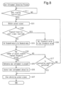
- the door entrapment detector 1 determines whether or not a door closing instruction is received (step S11). More specifically, when a door closing instruction output from the vehicle control board 4 is received via the door controller 2, the door 30 will be closed. Thus, the door entrapment detector 1 starts to detect whether or not the door 30 is in an entrapment state. If the door closing instruction is not received (step S11: NO), the door entrapment detector 1 waits for a door closing instruction.
- the door entrapment detector 1 obtains a detection signal (step S12). More specifically, when the first output signal is received from the first detection sensor 53, the obtainment unit 11 causes the first output signal to pass through the filter 12A to generate the first detection signal in which frequency components of vibration of the vehicle are reduced. When the second output signal is received from the second detection sensor 54, the obtainment unit 11 causes the second output signal to pass through the filter 12A to generate the second detection signal in which frequency components of vibration of the vehicle are reduced. The obtainment unit 11 transmits the first detection signal and the second detection signal to the determination unit 13.
- the door entrapment detector 1 determines whether or not the detection signal is greater than the determination value (step S13). More specifically, if the determination unit 13 determines that the detection signal is less than or equal to the determination value T2 (step S13: NO), the determination unit 13 determines whether or not a termination condition is satisfied (step S17). If the termination condition is not satisfied (step S17: NO), the determination unit 13 proceeds to step S12 and continues the process. If the termination condition is satisfied (step S17: YES), the determination unit 13 proceeds to step S16.
- the termination condition is a condition that does not require the door entrapment detection process, such as a condition in which a predetermined time has elapsed since the vehicle started traveling, a condition in which the rear end of the vehicle has passed the end of a platform, or a condition in which the speed of the vehicle exceeds a predetermined speed.
- step S13 determines that the detection signal is greater than the determination value T2 (step S13: YES)
- the determination unit 13 determines that the door 30 is in an entrapment state (step S14). More specifically, even when the output signal includes travel vibration of the vehicle, the determination unit 13 makes a determination based on the detection signal obtained by causing the output signal to pass through the filter 12A. Thus, the determination is made using the second determination value T2, which is smaller than the first determination value T1 used for determination of the output signal.
- the determination unit 13 continues to obtain detection signals and continues to make determinations until the detection value exceeds greater than the determination value T2 or the termination condition is satisfied.
- the door entrapment detector 1 outputs a door entrapment detection (step S15). If the determination unit 13 determines that the door 30 is in an entrapment state, the determination unit 13 reports the door entrapment detection to the door controller 2 to output the door entrapment detection to the vehicle control board 4 via the door controller 2.
- the door entrapment detector 1 stops obtaining detection signals (step S16) and ends the door entrapment detection process. More specifically, the obtainment unit 11 stops receiving output signals. Alternatively, the obtainment unit 11 may cause the first detection sensor 53 and the second detection sensor 54 to stop outputting output signals or may cause the first detection sensor 53 and the second detection sensor 54 to stop detecting pressure.
- the door entrapment detector 1 uses the detection sensors 53 and 54 and thus differs from a typical detector that uses a detection switch to detect door entrapment.
- the door entrapment detector 1 uses pressure variations caused by deformation of the elastic members 51 and 52 to reduce frequency components of vibration of the vehicle.
- the present embodiment has the advantages described below.
- a door entrapment detector according to a second embodiment will now be described with reference to Fig. 5 .
- the door entrapment detection process of the second embodiment differs from that of the first embodiment in that the travel state of the vehicle is taken into consideration when determination is made. The description will focus on the differences from the first embodiment.
- the door entrapment detector 1 obtains travel state information indicating the travel state of the vehicle from the vehicle control board 4 via the door controller 2.
- the travel state information indicates, for example, states of the vehicle including a standstill, traveling (powered-traveling), and braking (brake) and speed of the vehicle.
- the filter 12A of the detection signal generation unit 12 of the door entrapment detector 1 removes different frequency components depending on the travel state of the vehicle. As the speed of the vehicle increases, the lower limit of a frequency that is removed by the filter 12A is raised because the frequency of an output signal caused by the travel vibration increases. Additionally, when the speed of the vehicle is assumed to increase based on the state of the vehicle, the lower limit of a frequency that is removed by the filter 12A is raised. When the speed of the vehicle is assumed to decrease based on the state of the vehicle, the lower limit of a frequency that is removed by the filter 12A is lowered.
- the determination unit 13 of the door entrapment detector 1 makes a determination using different determination values depending on the travel state of the vehicle. As the speed of the vehicle increases, the determination value is increased because door entrapment is less likely to occur. Additionally, when the speed of the vehicle is assumed to increase based on the state of the vehicle, the determination value is increased. When the speed of the vehicle is assumed to decrease based on the state of the vehicle, the determination value is decreased.
- the door entrapment detector 1 obtains the travel state information (step S21). More specifically, the door entrapment detector 1 obtains the travel state information from the vehicle control board 4 via the door controller 2.
- the door entrapment detector 1 sets the filter 12A in accordance with the travel state (step S22). More specifically, the detection signal generation unit 12 changes the lower limit of a frequency that is removed by the filter 12A in accordance with the travel state.
- the door entrapment detector 1 obtains a detection signal (step S23). More specifically, the obtainment unit 11 obtains output signals from the first detection sensor 53 and the second detection sensor 54.
- the detection signal generation unit 12 causes the output signals to pass through the filter 12A to generate a detection signal in which frequency components of vibration of the vehicle are reduced, and transmits the detection signal to the determination unit 13.
- the door entrapment detector 1 sets the determination value in accordance with the travel state (step S24). More specifically, the determination unit 13 changes the determination value in accordance with the travel state.
- the door entrapment detector 1 determines whether or not the door 30 is in an entrapment state by comparing the detection signal that has passed through the filter 12A, which is set in accordance with the travel state, with the determination value that is set in accordance with the travel state (step S13).
- steps S14 to S17 is performed in the same manner as the first embodiment, and the door entrapment detection process is ended.
- the second embodiment has the advantages described below in addition to the advantages (1) and (2) of the first embodiment.
- Frequency components of vibration of the vehicle may differ depending on the travel state of the vehicle. Reduction of frequency components in accordance with the travel state of the vehicle further increases the accuracy for detecting door entrapment.
- a door entrapment detector according to a third embodiment will now be described with reference to Figs. 6 to 8 .
- the door entrapment detector of the third embodiment differs from that of the first embodiment in the determination of whether or not the door 30 is in an entrapment state. The description will focus on the differences from the first embodiment.
- a first detection sensor 73 which is arranged on the first door 31, is a pressure switch outputting an output signal when variation pressure of the empty space 51A in the first elastic member 51 exceeds a determination value.
- the first detection sensor 73 is connected to the empty space 51A by a tube 73A.
- a second detection sensor 74 which is arranged on the second door 32, is a pressure switch outputting an output signal when variation pressure of the empty space 52A in the second elastic member 52 exceeds a determination value.
- the second detection sensor 74 is connected to the empty space 52A by a tube 74A.
- the detection signal generation unit 12 of the door entrapment detector 1 does not include the filter 12A.
- the detection signal generation unit 12 counts the number of output signals included in first output signals output from the first detection sensor 73 and second output signals output from the second detection sensor 74 and exceeding a predetermined reference value (determination value).
- the detection signal generation unit 12 transmits the counted number to the determination unit 13 as a detection signal.
- the door entrapment detector 1 receives a powered-traveling start signal from the vehicle control board 4 via the door controller 2.
- the powered-traveling start signal is output in a powered-traveling state, for example, when speed X km/hour reaches 5 km/hour.
- the detection signal generation unit 12 counts the number of output signals that are included in output signals obtained by the obtainment unit 11 in a predetermined period and exceed the predetermined reference value (determination value) and uses the counted number as a detection signal.
- the determination unit 13 determines that the door 30 is in an entrapment state. More specifically, when the number of output signals that are included in at least one of the first output signals and the second output signals received from the obtainment unit 11 and exceed the predetermined reference value (determination value) is greater than or equal to the threshold value, the determination unit 13 determines that the door 30 is in an entrapment state.
- the door 30 being in an entrapment state is determined when the number of output signals that are included in just one of the first output signals and the second output signals and exceeding the predetermined reference value (determination value) is greater than or equal to the threshold value, the possibility of quickly detecting door entrapment increases. If the door 30 being in an entrapment state is determined when the number of output signals that are included in both of the first output signals and the second output signals and exceed the predetermined reference value (determination value) is greater than or equal to the threshold value, the possibility of accurately detecting door entrapment increases.
- the determination unit 13 reduces the effect of vibration caused by the traveling of the vehicle by changing the threshold value in accordance with whether the vehicle is traveling or at a standstill and determines whether or not the door 30 is in an entrapment state.
- the determination unit 13 obtains the powered-traveling start signal from the vehicle control board 4 via the door controller 2 as a drive start signal.
- the determination unit 13 determines that the vehicle is traveling and sets the threshold value to a second threshold value.
- the second threshold value is, for example, two.
- the determination unit 13 determines that the door 30 is in an entrapment state.
- the travel vibration may cause the first detection sensor 73 and/or the second detection sensor 74 to output an output signal.
- the threshold value for the vehicle being traveling is set to a greater number than the threshold value for the vehicle at a standstill.
- the determination unit 13 determines that the vehicle is at a standstill and sets the threshold value to a first threshold value.
- the first threshold value is, for example, one.
- the determination unit 13 determines that the door 30 is in an entrapment state.
- the door entrapment detector 1 obtains an output signal (step S31). More specifically, the obtainment unit 11 obtains output signals from the first detection sensor 73 and the second detection sensor 74. The detection signal generation unit 12 counts the number of output signals that are included in the output signals obtained by the obtainment unit 11 in a predetermined period and exceed the predetermined reference value (determination value). The detection signal generation unit 12 transmits the counted number to the determination unit 13 as a detection signal.
- the door entrapment detector 1 determines whether or not the powered-traveling start signal is received (step S32). More specifically, the determination unit 13 determines whether or not the vehicle is traveling based on whether or not the powered-traveling start signal is received. If the determination unit 13 determines that the powered-traveling start signal is received (step S32: YES), the determination unit 13 sets the threshold value to the second threshold value (step S38).
- step S32 determines that the powered-traveling start signal is not received (step S32: NO)
- the determination unit 13 sets the threshold value to the first threshold value (step S33).
- the door entrapment detector 1 determines whether or not the number of output signals included in the output signals and exceeding the predetermined reference value (determination value) has reached the threshold value (step S34). More specifically, if the determination unit 13 determines that the number of output signals included in the output signals and exceeding the predetermined reference value (determination value) has not reached the threshold value (step S34: NO), the determination unit 13 determines whether or not the termination condition is satisfied (step S17). If the termination condition is not satisfied (step S17: NO), the determination unit 13 proceeds to step S31 and continues the process. If the termination condition is satisfied (step S17: YES), the determination unit 13 proceeds to step S37.
- step S34 determines that the number of output signals included in the output signals and exceeding the predetermined reference value (determination value) has reached the threshold value (step S34: YES). More specifically, the determination unit 13 sets a threshold value different in accordance with whether the vehicle is traveling or at a standstill and makes a determination. Thus, even when output signals are output due to the travel vibration of the vehicle, the determination unit 13 reduces the effect of vibration caused by the traveling of the vehicle. As shown in Figs.
- the determination unit 13 determines that the door 30 is in an entrapment state. After it is determined that the door 30 is not in an entrapment state at a standstill, when the vehicle is traveling and two of the output signals exceed the predetermined reference value (determination value), the number of output signals reaches the second threshold value, or two. Thus, the determination unit 13 determines that the door 30 is in an entrapment state.
- the determination unit 13 continues to obtain output signals and continues to make determinations until the number of output signals included in the output signals and exceeding the predetermined reference value (determination value) reaches the threshold value or the termination condition is satisfied.
- the door entrapment detector 1 stops obtaining detection signals (step S37) and ends the door entrapment detection process. More specifically, the obtainment unit 11 may stop receiving output signals. Alternatively, the obtainment unit 11 may cause the first detection sensor 73 and the second detection sensor 74 to stop outputting output signals or may cause the first detection sensor 73 and the second detection sensor 74 to stop detecting pressure.
- the third embodiment has the advantages described below in addition to the advantage (1) of the first embodiment.
- the vehicle When the powered-traveling start signal of the vehicle is received, the vehicle receives driving force and starts to travel. Thus, when it is determined that the vehicle is traveling, the door entrapment detection process is performed.
- a door entrapment detector according to a fourth embodiment will now be described with reference to Figs. 9 and 10 .
- the door entrapment detector of the fourth embodiment differs from that of the third embodiment in the determination of whether the vehicle is traveling or at a standstill. The description will focus on the differences from the third embodiment.
- the door entrapment detector 1 receives a brake release signal from the vehicle control board 4 via the door controller 2.
- the determination unit 13 determines whether the vehicle is traveling or at a standstill based on whether or not the brake release signal is received.
- the determination unit 13 determines that the vehicle is traveling and sets the threshold value to the second threshold value.
- the second threshold value is, for example, two.
- the determination unit 13 determines that the door 30 is in an entrapment state.
- the travel vibration may cause the first detection sensor 73 and/or the second detection sensor 74 to output an output signal.
- the threshold value for the vehicle being traveling is set to a greater number than the threshold value for the vehicle at a standstill.
- the determination unit 13 determines that the vehicle is at a standstill and sets the threshold value to the first threshold value.
- the first threshold value is, for example, one.
- the determination unit 13 determines that the door 30 is in an entrapment state.
- the door entrapment detector 1 obtains an output signal (step S31). More specifically, the obtainment unit 11 obtains output signals from the first detection sensor 73 and the second detection sensor 74. The detection signal generation unit 12 counts the number of output signals that are included in the output signals obtained by the obtainment unit 11 in a predetermined period and exceed the predetermined reference value (determination value). The detection signal generation unit 12 transmits the counted number to the determination unit 13 as a detection signal.
- the door entrapment detector 1 determines whether or not the vehicle is at a standstill (step S42). More specifically, the determination unit 13 determines whether or not the vehicle is at a standstill based on whether or not the brake release signal is received. If the determination unit 13 determines that the brake release signal is not received, that is, the vehicle is at a standstill (step S42: YES), the determination unit 13 sets the threshold value to the first threshold value (step S33).
- step S42 determines that the brake release signal is received, that is, the vehicle is traveling (step S42: NO)
- the determination unit 13 sets the threshold value to the second threshold value (step S38).
- steps S34 to S37 and S17 is performed in the same manner as the third embodiment, and the door entrapment detection process is ended.
- the fourth embodiment has the advantage described below in addition to the advantage (1) of the first embodiment and the advantage (5) of the third embodiment.
- the first detection sensors 53 and 73 and the second detection sensors 54 and 74 are attached to the upper portion of the corresponding door.
- the first detection sensors 53 and 73 and the second detection sensors 54 and 74 may be attached to any position.
- the output signals of both the first detection sensor 53 and the second detection sensor 54 are used to determine whether or not the door 30 is in an entrapment state. Instead, the output signal of only one of the first detection sensor 53 and the second detection sensor 54 may be used to determine whether or not the door 30 is in an entrapment state.
- the detection signals of both the first detection sensor 73 and the second detection sensor 74 are used to determine whether or not the door 30 is in an entrapment state. Instead, the detection signal of only one of the first detection sensor 73 and the second detection sensor 74 may be used to determine whether or not the door 30 is in an entrapment state.
- the filter 12A removes different frequency components depending on the travel state of the vehicle, and different determination values are used depending on the travel state of the vehicle. However, only one of the filter 12A that removes different frequency components depending on the travel state of the vehicle and the determination values that differ depending on the travel state of the vehicle may be used.
- the filter 12A of the detection signal generation unit 12 removes signals having a frequency including frequency components of vibration of the vehicle or higher. Instead, the filter 12A of the detection signal generation unit 12 may remove signals having a frequency including only frequency components of vibration of the vehicle.
- the threshold value for a determination when the vehicle is traveling, the threshold value for a determination is set to the second threshold value.
- the threshold value is changed in accordance with the speed of the vehicle. More specifically, as the speed of the vehicle increases, the threshold value is set from the second threshold value to a third threshold value and then a fourth threshold value. The threshold value is set so that the first threshold value ⁇ the second threshold value ⁇ the third threshold value ⁇ the fourth threshold value. With such a setting, the threshold value is changed in accordance with the speed of the vehicle, and the accuracy for detecting door entrapment is further increased.
- the phrase "the threshold value is changed in accordance with the speed of the vehicle” includes the threshold value being changed in accordance with the vehicle is traveling or at a standstill.
- the door entrapment detector 1 includes the detection signal generation unit 12 and the determination unit 13.
- the determination unit 13 may perform the function of the detection signal generation unit 12. More specifically, the determination unit 13 may count the number of output signals included in the output signals obtained by the obtainment unit 11 in the predetermined period and exceeding the predetermined reference value (determination value) and determine that the door 30 is in an entrapment state when the counted number is greater than or equal to the threshold value.
- a pressure sensor is used as the detection sensor.
- a pressure switch is used as the detection sensor.
- a strain sensor may be used to directly measure a deformation amount of the elastic members 51 and 52. More specifically, the phrase "detecting deformation of an elastic member" includes not only a mode indirectly detecting deformation of the elastic member by detecting a change in the pressure of the hollow portion in the elastic member but also a mode directly detecting deformation of the elastic member.
- the door controller 2 may perform the function of the door entrapment detector 1. More specifically, the door controller 2 includes the obtainment unit 11, the detection signal generation unit 12, and the determination unit 13 in addition to the door opening-closing unit 21 and the door depressurization unit 22.
Landscapes
- Physics & Mathematics (AREA)
- Fluid Mechanics (AREA)
- Power-Operated Mechanisms For Wings (AREA)
- Automobile Manufacture Line, Endless Track Vehicle, Trailer (AREA)
Applications Claiming Priority (1)
| Application Number | Priority Date | Filing Date | Title |
|---|---|---|---|
| JP2017224882A JP6990567B2 (ja) | 2017-11-22 | 2017-11-22 | 戸挟み検知装置及びドア開閉装置 |
Publications (2)
| Publication Number | Publication Date |
|---|---|
| EP3489447A1 EP3489447A1 (en) | 2019-05-29 |
| EP3489447B1 true EP3489447B1 (en) | 2023-05-31 |
Family
ID=64402045
Family Applications (1)
| Application Number | Title | Priority Date | Filing Date |
|---|---|---|---|
| EP18207192.8A Active EP3489447B1 (en) | 2017-11-22 | 2018-11-20 | Door entrapment detector and door opening-closing device |
Country Status (4)
| Country | Link |
|---|---|
| EP (1) | EP3489447B1 (ja) |
| JP (1) | JP6990567B2 (ja) |
| CN (1) | CN109812166B (ja) |
| TW (1) | TWI695792B (ja) |
Families Citing this family (2)
| Publication number | Priority date | Publication date | Assignee | Title |
|---|---|---|---|---|
| FR3097637B1 (fr) * | 2019-06-18 | 2021-05-28 | Psa Automobiles Sa | Procédé de gestion d’un mécanisme d’assistance motorisée à l’ouverture d’un ouvrant de véhicule automobile |
| CN110566075B (zh) * | 2019-09-29 | 2020-11-03 | 白云帆 | 一种自动防护屏蔽门 |
Family Cites Families (12)
| Publication number | Priority date | Publication date | Assignee | Title |
|---|---|---|---|---|
| JPH09317322A (ja) * | 1996-05-31 | 1997-12-09 | Sensor Technol Kk | 車両等の自動開閉式ドア又は窓等の挟み込み防止装置 |
| CN1152187C (zh) * | 1999-05-13 | 2004-06-02 | 松下电器产业株式会社 | 压敏传感器、目标检测装置和开闭装置 |
| JP3182411B2 (ja) * | 1999-08-11 | 2001-07-03 | 川崎重工業株式会社 | 戸挟み検知装置 |
| GB2358220B (en) * | 1999-10-05 | 2003-05-28 | Manganese Bronze Components Lt | Detection of obstruction of doors |
| JP3931732B2 (ja) * | 2002-05-31 | 2007-06-20 | アイシン精機株式会社 | 開閉体の挟み込み検知装置 |
| EP1612361A1 (en) * | 2003-04-09 | 2006-01-04 | Matsushita Electric Industrial Co., Ltd. | Moving device and open/close control device for moving body |
| JP2004308304A (ja) * | 2003-04-09 | 2004-11-04 | Matsushita Electric Ind Co Ltd | 移動体開閉制御装置 |
| JP2006064594A (ja) * | 2004-08-27 | 2006-03-09 | Aisin Seiki Co Ltd | 挟み込み検出装置 |
| WO2007000797A1 (ja) * | 2005-06-27 | 2007-01-04 | Aisin Seiki Kabushiki Kaisha | 車両用開閉体制御装置 |
| JP4914131B2 (ja) * | 2006-06-30 | 2012-04-11 | パナソニック電工Sunx株式会社 | 戸挟み検出装置 |
| JP2012076566A (ja) * | 2010-09-30 | 2012-04-19 | Panasonic Electric Works Sunx Co Ltd | 戸挟み検出装置 |
| JP6548410B2 (ja) * | 2015-03-04 | 2019-07-24 | 西日本旅客鉄道株式会社 | 戸挟み検出装置 |
-
2017
- 2017-11-22 JP JP2017224882A patent/JP6990567B2/ja active Active
-
2018
- 2018-11-20 CN CN201811386388.8A patent/CN109812166B/zh active Active
- 2018-11-20 TW TW107141280A patent/TWI695792B/zh active
- 2018-11-20 EP EP18207192.8A patent/EP3489447B1/en active Active
Also Published As
| Publication number | Publication date |
|---|---|
| EP3489447A1 (en) | 2019-05-29 |
| JP2019093900A (ja) | 2019-06-20 |
| CN109812166A (zh) | 2019-05-28 |
| TWI695792B (zh) | 2020-06-11 |
| JP6990567B2 (ja) | 2022-01-12 |
| TW201927612A (zh) | 2019-07-16 |
| CN109812166B (zh) | 2021-10-22 |
Similar Documents
| Publication | Publication Date | Title |
|---|---|---|
| EP2261092B1 (en) | Controller of industrial vehicle and industrial vehicle mounting the same | |
| JP2013002110A (ja) | 開閉体制御装置 | |
| EP3489447B1 (en) | Door entrapment detector and door opening-closing device | |
| US10464399B2 (en) | Vehicle window opening device | |
| US11365580B2 (en) | Method and adjusting device for adjusting a vehicle adjusting part with output status information | |
| KR101106475B1 (ko) | 모터 작동식 폐쇄 시스템용 끼임 방지 방법 및 장치 | |
| CN104340129A (zh) | 车辆的侧梯的操作装置和操作控制方法 | |
| JP2007315069A (ja) | 車両用自動開閉装置 | |
| KR101323028B1 (ko) | 안티-핀치 시스템 제어 방법 및 이러한 방법을 사용하는 장치 | |
| US6924614B2 (en) | Opening and closing control device for opening and closing member of vehicle | |
| US7295909B2 (en) | Method for the detection of an impact | |
| EP3489446B1 (en) | Door entrapment detector and door opening-closing device | |
| EP1112897B1 (en) | Device for controlling expansion of an air bag apparatus | |
| JP2016159847A (ja) | 戸挟み検出装置 | |
| CN107327243A (zh) | 一种电动尾门控制方法 | |
| JP7181788B2 (ja) | 鉄道車両の戸挟み検出装置 | |
| KR101856866B1 (ko) | 엘리베이터 도어의 광학 안전 센서 진단 시스템 | |
| JP2014076777A (ja) | 車両用ドア制御装置 | |
| KR101261777B1 (ko) | 차량용 후방인식 안전장치 | |
| JP3092487B2 (ja) | サンルーフの開閉駆動制御装置 | |
| KR102014447B1 (ko) | 오토트렁크 잠금장치 제어 시스템 및 잠금장치 동작 방법 | |
| KR20170072665A (ko) | 차량용 도어 제어 방법 및 장치 | |
| KR0180438B1 (ko) | 커브길에서 주행속도 제어장치 및 방법 | |
| JPH0783952A (ja) | 加速度検出装置 | |
| KR20100042143A (ko) | 차량 도어 제어 장치 및 방법 |
Legal Events
| Date | Code | Title | Description |
|---|---|---|---|
| PUAI | Public reference made under article 153(3) epc to a published international application that has entered the european phase |
Free format text: ORIGINAL CODE: 0009012 |
|
| STAA | Information on the status of an ep patent application or granted ep patent |
Free format text: STATUS: REQUEST FOR EXAMINATION WAS MADE |
|
| 17P | Request for examination filed |
Effective date: 20181120 |
|
| AK | Designated contracting states |
Kind code of ref document: A1 Designated state(s): AL AT BE BG CH CY CZ DE DK EE ES FI FR GB GR HR HU IE IS IT LI LT LU LV MC MK MT NL NO PL PT RO RS SE SI SK SM TR |
|
| AX | Request for extension of the european patent |
Extension state: BA ME |
|
| STAA | Information on the status of an ep patent application or granted ep patent |
Free format text: STATUS: EXAMINATION IS IN PROGRESS |
|
| 17Q | First examination report despatched |
Effective date: 20200324 |
|
| STAA | Information on the status of an ep patent application or granted ep patent |
Free format text: STATUS: EXAMINATION IS IN PROGRESS |
|
| STAA | Information on the status of an ep patent application or granted ep patent |
Free format text: STATUS: EXAMINATION IS IN PROGRESS |
|
| GRAP | Despatch of communication of intention to grant a patent |
Free format text: ORIGINAL CODE: EPIDOSNIGR1 |
|
| STAA | Information on the status of an ep patent application or granted ep patent |
Free format text: STATUS: GRANT OF PATENT IS INTENDED |
|
| INTG | Intention to grant announced |
Effective date: 20221206 |
|
| GRAS | Grant fee paid |
Free format text: ORIGINAL CODE: EPIDOSNIGR3 |
|
| GRAA | (expected) grant |
Free format text: ORIGINAL CODE: 0009210 |
|
| STAA | Information on the status of an ep patent application or granted ep patent |
Free format text: STATUS: THE PATENT HAS BEEN GRANTED |
|
| AK | Designated contracting states |
Kind code of ref document: B1 Designated state(s): AL AT BE BG CH CY CZ DE DK EE ES FI FR GB GR HR HU IE IS IT LI LT LU LV MC MK MT NL NO PL PT RO RS SE SI SK SM TR |
|
| REG | Reference to a national code |
Ref country code: GB Ref legal event code: FG4D Ref country code: CH Ref legal event code: EP |
|
| REG | Reference to a national code |
Ref country code: DE Ref legal event code: R096 Ref document number: 602018050397 Country of ref document: DE |
|
| REG | Reference to a national code |
Ref country code: AT Ref legal event code: REF Ref document number: 1571002 Country of ref document: AT Kind code of ref document: T Effective date: 20230615 |
|
| REG | Reference to a national code |
Ref country code: IE Ref legal event code: FG4D |
|
| P01 | Opt-out of the competence of the unified patent court (upc) registered |
Effective date: 20230523 |
|
| REG | Reference to a national code |
Ref country code: LT Ref legal event code: MG9D |
|
| REG | Reference to a national code |
Ref country code: NL Ref legal event code: MP Effective date: 20230531 |
|
| REG | Reference to a national code |
Ref country code: AT Ref legal event code: MK05 Ref document number: 1571002 Country of ref document: AT Kind code of ref document: T Effective date: 20230531 |
|
| PG25 | Lapsed in a contracting state [announced via postgrant information from national office to epo] |
Ref country code: SE Free format text: LAPSE BECAUSE OF FAILURE TO SUBMIT A TRANSLATION OF THE DESCRIPTION OR TO PAY THE FEE WITHIN THE PRESCRIBED TIME-LIMIT Effective date: 20230531 Ref country code: NO Free format text: LAPSE BECAUSE OF FAILURE TO SUBMIT A TRANSLATION OF THE DESCRIPTION OR TO PAY THE FEE WITHIN THE PRESCRIBED TIME-LIMIT Effective date: 20230831 Ref country code: ES Free format text: LAPSE BECAUSE OF FAILURE TO SUBMIT A TRANSLATION OF THE DESCRIPTION OR TO PAY THE FEE WITHIN THE PRESCRIBED TIME-LIMIT Effective date: 20230531 Ref country code: AT Free format text: LAPSE BECAUSE OF FAILURE TO SUBMIT A TRANSLATION OF THE DESCRIPTION OR TO PAY THE FEE WITHIN THE PRESCRIBED TIME-LIMIT Effective date: 20230531 |
|
| PG25 | Lapsed in a contracting state [announced via postgrant information from national office to epo] |
Ref country code: RS Free format text: LAPSE BECAUSE OF FAILURE TO SUBMIT A TRANSLATION OF THE DESCRIPTION OR TO PAY THE FEE WITHIN THE PRESCRIBED TIME-LIMIT Effective date: 20230531 Ref country code: PL Free format text: LAPSE BECAUSE OF FAILURE TO SUBMIT A TRANSLATION OF THE DESCRIPTION OR TO PAY THE FEE WITHIN THE PRESCRIBED TIME-LIMIT Effective date: 20230531 Ref country code: NL Free format text: LAPSE BECAUSE OF FAILURE TO SUBMIT A TRANSLATION OF THE DESCRIPTION OR TO PAY THE FEE WITHIN THE PRESCRIBED TIME-LIMIT Effective date: 20230531 Ref country code: LV Free format text: LAPSE BECAUSE OF FAILURE TO SUBMIT A TRANSLATION OF THE DESCRIPTION OR TO PAY THE FEE WITHIN THE PRESCRIBED TIME-LIMIT Effective date: 20230531 Ref country code: LT Free format text: LAPSE BECAUSE OF FAILURE TO SUBMIT A TRANSLATION OF THE DESCRIPTION OR TO PAY THE FEE WITHIN THE PRESCRIBED TIME-LIMIT Effective date: 20230531 Ref country code: IS Free format text: LAPSE BECAUSE OF FAILURE TO SUBMIT A TRANSLATION OF THE DESCRIPTION OR TO PAY THE FEE WITHIN THE PRESCRIBED TIME-LIMIT Effective date: 20230930 Ref country code: HR Free format text: LAPSE BECAUSE OF FAILURE TO SUBMIT A TRANSLATION OF THE DESCRIPTION OR TO PAY THE FEE WITHIN THE PRESCRIBED TIME-LIMIT Effective date: 20230531 Ref country code: GR Free format text: LAPSE BECAUSE OF FAILURE TO SUBMIT A TRANSLATION OF THE DESCRIPTION OR TO PAY THE FEE WITHIN THE PRESCRIBED TIME-LIMIT Effective date: 20230901 |
|
| PG25 | Lapsed in a contracting state [announced via postgrant information from national office to epo] |
Ref country code: FI Free format text: LAPSE BECAUSE OF FAILURE TO SUBMIT A TRANSLATION OF THE DESCRIPTION OR TO PAY THE FEE WITHIN THE PRESCRIBED TIME-LIMIT Effective date: 20230531 |
|
| PG25 | Lapsed in a contracting state [announced via postgrant information from national office to epo] |
Ref country code: SK Free format text: LAPSE BECAUSE OF FAILURE TO SUBMIT A TRANSLATION OF THE DESCRIPTION OR TO PAY THE FEE WITHIN THE PRESCRIBED TIME-LIMIT Effective date: 20230531 |
|
| PGFP | Annual fee paid to national office [announced via postgrant information from national office to epo] |
Ref country code: GB Payment date: 20231123 Year of fee payment: 6 |
|
| PG25 | Lapsed in a contracting state [announced via postgrant information from national office to epo] |
Ref country code: SM Free format text: LAPSE BECAUSE OF FAILURE TO SUBMIT A TRANSLATION OF THE DESCRIPTION OR TO PAY THE FEE WITHIN THE PRESCRIBED TIME-LIMIT Effective date: 20230531 Ref country code: SK Free format text: LAPSE BECAUSE OF FAILURE TO SUBMIT A TRANSLATION OF THE DESCRIPTION OR TO PAY THE FEE WITHIN THE PRESCRIBED TIME-LIMIT Effective date: 20230531 Ref country code: RO Free format text: LAPSE BECAUSE OF FAILURE TO SUBMIT A TRANSLATION OF THE DESCRIPTION OR TO PAY THE FEE WITHIN THE PRESCRIBED TIME-LIMIT Effective date: 20230531 Ref country code: PT Free format text: LAPSE BECAUSE OF FAILURE TO SUBMIT A TRANSLATION OF THE DESCRIPTION OR TO PAY THE FEE WITHIN THE PRESCRIBED TIME-LIMIT Effective date: 20231002 Ref country code: EE Free format text: LAPSE BECAUSE OF FAILURE TO SUBMIT A TRANSLATION OF THE DESCRIPTION OR TO PAY THE FEE WITHIN THE PRESCRIBED TIME-LIMIT Effective date: 20230531 Ref country code: DK Free format text: LAPSE BECAUSE OF FAILURE TO SUBMIT A TRANSLATION OF THE DESCRIPTION OR TO PAY THE FEE WITHIN THE PRESCRIBED TIME-LIMIT Effective date: 20230531 Ref country code: CZ Free format text: LAPSE BECAUSE OF FAILURE TO SUBMIT A TRANSLATION OF THE DESCRIPTION OR TO PAY THE FEE WITHIN THE PRESCRIBED TIME-LIMIT Effective date: 20230531 |
|
| REG | Reference to a national code |
Ref country code: DE Ref legal event code: R097 Ref document number: 602018050397 Country of ref document: DE |
|
| PLBE | No opposition filed within time limit |
Free format text: ORIGINAL CODE: 0009261 |
|
| STAA | Information on the status of an ep patent application or granted ep patent |
Free format text: STATUS: NO OPPOSITION FILED WITHIN TIME LIMIT |
|
| PG25 | Lapsed in a contracting state [announced via postgrant information from national office to epo] |
Ref country code: SI Free format text: LAPSE BECAUSE OF FAILURE TO SUBMIT A TRANSLATION OF THE DESCRIPTION OR TO PAY THE FEE WITHIN THE PRESCRIBED TIME-LIMIT Effective date: 20230531 |
|
| 26N | No opposition filed |
Effective date: 20240301 |