EP3488719A1 - Einrichtung zur partiellen verkürzung der länge flexibler flächen in deren randbereich - Google Patents
Einrichtung zur partiellen verkürzung der länge flexibler flächen in deren randbereich Download PDFInfo
- Publication number
- EP3488719A1 EP3488719A1 EP18000867.4A EP18000867A EP3488719A1 EP 3488719 A1 EP3488719 A1 EP 3488719A1 EP 18000867 A EP18000867 A EP 18000867A EP 3488719 A1 EP3488719 A1 EP 3488719A1
- Authority
- EP
- European Patent Office
- Prior art keywords
- bend
- skirt
- length
- waistband
- edge area
- Prior art date
- Legal status (The legal status is an assumption and is not a legal conclusion. Google has not performed a legal analysis and makes no representation as to the accuracy of the status listed.)
- Granted
Links
Images

Classifications
-
- A—HUMAN NECESSITIES
- A41—WEARING APPAREL
- A41F—GARMENT FASTENINGS; SUSPENDERS
- A41F1/00—Fastening devices specially adapted for garments
-
- A—HUMAN NECESSITIES
- A41—WEARING APPAREL
- A41F—GARMENT FASTENINGS; SUSPENDERS
- A41F9/00—Belts, girdles, or waistbands for trousers or skirts
- A41F9/02—Expansible or adjustable belts or girdles ; Adjustable fasteners comprising a track and a slide member
- A41F9/025—Adjustable belts or girdles
Definitions
- a firm pants or waistband should fix the respective garment on the hips of the respective wearer. If the width dimensions of the hips and the diameter of the tight waistband are not matched, the respective garment slips down. This is particularly problematic when the wearer of the respective garment gradually reduces his body measurements for whatever reason.
- DE-Gbm 297 09 261 U1 describes a U-shaped bent sheet metal part, which is pushed from the top of the belt whose outer leg has unilaterally open recesses in the loop-like shortened a trouser or skirt or belt can be inserted, the characterized in its length is shortened. Due to the multiple slits, a gradual shortening is possible, on the one hand, the power consumption of the unilaterally set tines is very limited and on the other hand at Movements of the wearer resulting forces are not negligible. As a result, a skewing of the tines occurs quite quickly, so that the garment provided with it slips off. Thus, the proposed solution is permanently unusable.
- the object of the invention was therefore to find a solution by means of which a rapid and permanent partial shortening of the longitudinal extent of the edge region of a flexible surface, such as a trouser or skirt waistband is given.
- the object is achieved by a piece of suitable profile material, usually round spring steel wire of sufficient static strength, so U-shaped undergoes a first turn, that the two resulting unilaterally connected legs on the other side have an equal length. Based on their length both are bent in one half of their length on one side by 180 degrees, so that in the side view second turns are visible, which are substantially at right angles to the first turn and insofar further U-shaped configurations are given.
- suitable profile material usually round spring steel wire of sufficient static strength
- the free ends of the two legs press on the pants or skirt or the like and thus can lead there to unwanted wear. Both ends are therefore preferably opposite to the sides bent so that the specific burden on the underlying tissue of the trousers relationship skirt skirt or the like or a (lower) garment decreases and thus improves the wear behavior. The reduction is then maximum when the two ends each at right angles are bent.
- the trouser or skirt waistband or the like does not slip down and dissolves from the proposed device or this is pushed away by movements upwards, in an expedient embodiment above the first turn outwardly pointing kink executed, so there from the inside the specific pressure on the trouser or skirt waistband or the like increases and this is fixed in its position and does not slip downwards.
- the proposed device With the help of the proposed device, it is possible to reduce the diameter of a trouser or skirt waistband or the like reliable and sustainable means of a spatially small inconspicuous device without having to take the services of a tailor, as quasi a so-called darts is replaced and easy can be carried. It is also possible to use several proposed devices on a garment. By lying above the first turn and before the second turn outward kink, a relative captive is given.
- a profile material preferably round spring steel, is cut to about 2.5 to 3 times the expected width of a skirt waistband 4. In half this piece is over bent about 180 degrees, so that both formed on a first turn 2 unilaterally connected leg 1 have an equal length after the first turn 2. Based on their length both are bent in one half of their length on one side by 180 degrees, so again in the side view second turns 3 are visible and thus are given a further U-shaped designs.
- the first bend 2 and the second turns 3 are at an angle of about 90 degrees to each other.
- the proposed device With the visible in the side view second bends 3, the proposed device is placed with its open side down on a skirt collar 4 that the first turn 2 on the outside of the same and pointing down to lie and the free leg 1 the skirt waistband 4th are facing. At the moment of Aufsteckens on the skirt collar 4 of the skirt collar 4 has been placed in an outwardly visible visible fold 5 in such a way that the fold 5 between the two spaced from each other free ends 6 of the device lying facing outwards and related to the skirt 4 outer first turn 2 is threaded umschlingend. About the second turns 3, the proposed device is thus on the top of the skirt collar 4 and slipping down is not possible.
Landscapes
- Engineering & Computer Science (AREA)
- Textile Engineering (AREA)
- Details Of Garments (AREA)
- Professional, Industrial, Or Sporting Protective Garments (AREA)
Abstract
Description
- Die Erfindung betrifft eine Einrichtung zur partiellen Verkürzung der Länge von flexiblen Flächen in deren Randbereich oder bei deren streifenartiger Ausbildung, wie das bei flexiblen Gürteln, einem festen Hosen- oder Rockbund und dergleichen der Fall ist.
- Ein fester Hosen- oder Rockbund soll das jeweilige Kleidungsstück auf den Hüften des jeweiligen Trägers fixieren. Sind die Breitenmaße der Hüften und der Durchmesser des festen Rockbundes nicht aufeinander abgestimmt, rutscht das jeweilige Kleidungsstück nach unten. Das ist insbesondere auch dann problematisch, wenn der Träger des jeweiligen Kleidungsstückes seine Körpermaße aus welchen Gründen auch immer sukzessive verringert.
- In derartigen Fällen ist es üblich, in der jeweiligen Fläche eine sogenannten Abnäher einzuarbeiten, um die weitere Tragefähigkeit zu gewährleisten. Das ist nicht möglich, wenn nahezu zeitnah die Möglichkeit der Inanspruchnahme einer geeigneten Einrichtung zur Realisierung der Veränderung und / oder Fachkraft nicht gegeben ist.
- Es hat deshalb nicht an Vorschlägen zur Abhilfe derartiger Situationen gefehlt.
- So wird nach
DE 6903392U im Hüftbereich eine Art verkürzter Hosenträger verwandt, der im Achselbereich eines Trägers eines Hemdes verdeckt befestigt ist, sodass er vom Arm des Trägers verdeckt und somit unauffällig wird. Diese Lösung ist nicht ohne spezifische Gestaltung des jeweiligen Hemdes realisierbar und bedeutet das vorsorgliche Mitführen eines verändert gestalteten relativ großen Hosenträgers. - DE-Gbm 297 09 261 U1 beschreibt ein U-förmig gebogenes Blechteil, das von oben auf den Gürtel geschoben wird dessen äußerer Schenkel einseitig offene Aussparungen aufweist, in die schlingenartig verkürzt ein Hosen- beziehungsweise Rockbund oder ein Gürtel eingelegt werden kann, der dadurch in seiner Länge verkürzt wird. Durch die Mehrfachschlitzung ist eine stufenweise Verkürzung möglich, wobei einerseits die Kraftaufnahme der einseitig festgelegten Zinken sehr begrenzt ist und andererseits die bei Bewegungen des Trägers entstehenden Kräfte nicht unerheblich sind. Demzufolge tritt recht schnell ein Schiefziehen der Zinken ein, sodass das damit versehene Kleidungsstück abrutscht. Damit ist die vorgeschlagene Lösung dauerhaft unbrauchbar.
- Aufgabe der Erfindung war es deshalb, eine Lösung zu finden, mit deren Hilfe schnell und dauerhaft eine partielle Verkürzung der Längsausdehnung des Randbereiches einer flexiblen Fläche, wie das ein Hosen- oder Rockbund ist, gegeben ist.
- Die Aufgabe wird gelöst, indem ein Stück geeignetes Profilmaterial, im Regelfall runder Federstahldraht hinreichender statischer Festigkeit, so U-förmig eine erste Abbiegung erfährt, dass die beiden entstehenden einseitig verbundenen Schenkel andersseitig eine gleiche Länge aufweisen. Bezogen auf deren Länge werden beide in der Hälfte ihrer Länge gemeinsam einseitig um 180 Winkelgrad abgebogen, sodass in der Seitenansicht zweite Abbiegungen sichtbar werden, die sich im wesentlichen in einem rechten Winkel zur ersten Abbiegung befinden und insoweit weitere U-förmige Gestaltungen gegeben sind.
- Diese in der Seitenansicht weiteren zweiten Abbiegungen werden mit ihrer offenen Seite so nach unten auf den Hosen- beziehungsweise Rockbund oder dergleichen gesteckt, dass die zuerst erfolgte Abbiegung auf der Außenseite desselben und nach unten zeigend zu liegen kommt und die freien Schenkel dem Hosen- beziehungsweise Rockbund oder dergleichen zugewandt sind. Im Moment des Aufsteckens auf den Rock- beziehungsweise Hosenbund oder dergleichen ist der Hosen- beziehungsweise Rockbund oder dergleichen in eine nach außen sichtbare Falte zu legen, so, dass die Falte zwischen die beiden beabstandet zueinander freien Enden der Einrichtung liegend nach außen zeigend ist und die bezogen auf den Hosen- beziehungsweise Rockbund oder dergleichen außenliegende Abbiegung umschlingend eingefädelt ist.
- Die freien Enden der beiden Schenkel drücken dabei auf den Hosen- beziehungsweise Rockbund oder dergleichen und können demzufolge dort zum unerwünschten Verschleiß führen. Beide Enden sind vorzugsweise deshalb entgegengesetzt nach den Seiten hin abgebogen, damit sich die spezifische Belastung für das darunter befindliche Gewebe des Hosen- beziehungs-weise Rockbundes oder dergleichen oder eines (Unter-)Bekleidungsstückes verringert und sich damit das Verschleißverhalten verbessert. Die Verringerung ist dann maximal, wenn die beiden Enden jeweils im rechten Winkel abgebogen sind.
- Damit der Hosen- beziehungsweise Rockbund oder dergleichen nicht nach unten abrutscht und sich aus der vorgeschlagenen Einrichtung löst beziehungsweise diese durch Bewegungen nach oben weggedrückt wird, ist in einer zweckmäßigen Ausgestaltung oberhalb der ersten Abbiegung ein nach außen hin zeigender Knick ausgeführt, sodass sich dort von innen her der spezifische Druck auf den Hosen- beziehungsweise Rockbund oder dergleichen erhöht und dieser in seiner Lage fixiert ist und nicht nach unten abrutscht.
- Es versteht sich von selbst, dass hinsichtlich der Einrichtung besondere ästhetische Anforderungen realisierbar sind, auch was eine eventuell gewünschte von oben her aufschiebbare Abdeckkappe betrifft.
- Mit Hilfe der vorgeschlagenen Einrichtung ist es möglich, den Durchmesser eines Hosen- beziehungsweise Rockbundes oder dergleichen zuverlässig und nachhaltig mittels einer räumlich kleinen unauffälligen Einrichtung zu verringern ohne die Leistungen eines Schneiders in Anspruch nehmen zu müssen, da quasi ein sogenannter Abnäher ersetzt wird und die leicht mitgeführt werden kann. Es ist ebenso möglich, mehrere vorgeschlagene Einrichtungen an einem Kleidungsstück einzusetzen. Durch den oberhalb der ersten Abbiegung und vor der zweiten Abbiegung liegenden nach außen gerichteten Knick ist eine relative Unverlierbarkeit gegeben.
- Die Erfindung soll nachfolgend an einem Ausführungsbeispiel näher erläutert werden. In der zugehörigen Zeichnung zeigen
- Fig. 1
- die Grundform mit der ersten und der zweiten Abbiegung,
- Fig. 2
- die Idealform in der Vorderansicht, der Seitenansicht und der Draufsicht,
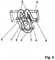
- Fig. 3
- die Einrichtung in der Perspektive mit einem eingelegten Hosenbund.
- Ein Profilmaterial, vorzugsweise runder Federstahl, ist auf etwa die 2,5- bis 3-fache zu erwartende Breite eines Rockbundes 4 zugeschnitten. In der Hälfte ist dieses Stück um etwa 180 Winkelgrad abgebogen, sodass beiden über eine erste Abbiegung 2 entstandenen einseitig verbundenen Schenkel 1 eine gleiche Länge nach der ersten Abbiegung 2 aufweisen. Bezogen auf deren Länge werden beide in der Hälfte ihrer Länge gemeinsam einseitig um 180 Winkelgrad abgebogen, sodass in der Seitenansicht erneut zweite Abbiegungen 3 sichtbar werden und somit eine weitere U-förmige Gestaltungen gegeben sind. Die erste Abbiegung 2 und die zweiten Abbiegungen 3 befinden sich dabei in einem Winkel von etwa 90 Winkelgrad zueinander.
- Mit den in der Seitenansicht sichtbaren zweiten Abbiegungen 3 wird die vorgeschlagene Einrichtung mit ihrer offenen Seite so nach unten auf einen Rockbund 4 gesteckt, dass die erste Abbiegung 2 auf der Außenseite desselben und nach unten zeigend zu liegen kommt und die freien Schenkel 1 dem Rockbund 4 zugewandt sind. Im Moment des Aufsteckens auf den Rockbund 4 ist der Rockbund 4 in eine nach außen entstehende sichtbare Falte 5 gelegt worden und zwar so, dass die Falte 5 zwischen die beiden beabstandet zueinander freien Enden 6 der Einrichtung liegend nach außen zeigend und die bezogen auf den Rockbund 4 außenliegende erste Abbiegung 2 umschlingend eingefädelt ist. Über die zweiten Abbiegungen 3 liegt die vorgeschlagene Einrichtung damit auf der Oberkante des Rockbundes 4 auf und ein Abrutschen nach unten ist nicht möglich.
- Die freien Enden der beiden Schenkel 1 drücken dabei auf den unteren Teil des Rockbundes 4 oder des angenähten Gewebes und können dort zum unerwünschten Verschleiß führen. Beide Enden 6 sind deshalb beispielhaft entgegengesetzt nach den Seiten hin abgebogen, damit sich die spezifische Belastung für das darunter befindliche Gewebe des Rockbundes 4 oder eines getragenen Unterbekleidungsstückes verringert.
- Damit der Rockbund 4 nicht nach unten abrutscht und sich aus der vorgeschlagenen Einrichtung löst beziehungsweise diese nach oben weggedrückt wird, ist oberhalb der ersten Abbiegung 2 und vor der zweiten Abbiegung 3 liegend der beiden Schenkel 1 vom Körper des Trägers wegführend ein leichter Knick 7 ausgeführt, sodass sich dort von innen her der spezifische Druck auf den Rockbund 4 erhöht und nach unten hin ein Abrutschen verhindert wird.
- Aufstellung der verwendeten Bezugszeichen:
Schenkel 1 erste Abbiegung 2 zweite Abbiegungen 3 Rockbund 4 Falte 5 Enden 6 Knick 7
Claims (3)
- Einrichtung zur partiellen Verkürzung der Länge von flexiblen Flächen in deren Randbereich oder bei deren streifenartiger Ausbildung dadurch gekennzeichnet, dass Profilmaterial U-förmig hälftig eine erste Abbiegung (2) aufweist, die beiden entstandenen einseitig verbundenen Schenkel (1) andersseitig eine gleiche Länge aufweisen, beide in der Hälfte ihrer Länge gemeinsam einseitig um 180 Winkelgrad abgebogen werden, sodass jeder eine zweite Abbiegung (3) aufweist, beide zweiten Abbiegungen (3) mit der ersten Abbiegung (2) einen im wesentlichen rechten Winkel bildend ausgestaltet sind, sodass in der Seitenansicht diese zweiten Abbiegungen (3) sichtbar werden und eine weitere U-förmige Gestaltung gegeben ist, die erfindungsgemäße Einrichtung mit ihrer offenen Seite so nach unten auf einen Hosen- beziehungsweise Rockbund (4) oder dergleichen aufgesteckt ist, dass die erste Abbiegung (2) auf der Außenseite desselben und nach unten zeigend zu liegen kommt und die freien Schenkel dem Hosenbeziehungsweise Rockbund (4) oder dergleichen zugewandt sind, der zu sichernde Hosen- beziehungsweise Rockbund (4) oder dergleichen so in eine nach außen sichtbare Falte (5) gelegt ist, dass die Falte (5) zwischen die beiden beabstandet zueinander freien Enden (6) der Einrichtung liegend nach außen zeigend und die bezogen auf den Hosen- beziehungsweise Rockbund (4) oder dergleichen außenliegende erste Abbiegung (2) umschlingend eingefädelt ist.
- Einrichtung nach Patentanspruch 1 dadurch gekennzeichnet, dass die freien Enden (6) der beiden Schenkel (1) entgegengesetzt nach den Seiten hin abgebogen sind.
- Einrichtung nach einem der Patentansprüche 1 oder 2 dadurch gekennzeichnet, dass oberhalb der ersten Abbiegung (2) und vor der jeweils zweiten Abbiegung (3) liegend beide Schenkel (1) einen nach außen hin weisenden Knick (7) aufweisend ausgeführt sind.
Applications Claiming Priority (1)
| Application Number | Priority Date | Filing Date | Title |
|---|---|---|---|
| DE102017010967.2A DE102017010967B3 (de) | 2017-11-27 | 2017-11-27 | Einrichtung zur partiellen Verkürzung der Länge flexibler Flächen in deren Randbereich |
Publications (2)
| Publication Number | Publication Date |
|---|---|
| EP3488719A1 true EP3488719A1 (de) | 2019-05-29 |
| EP3488719B1 EP3488719B1 (de) | 2022-10-26 |
Family
ID=64267419
Family Applications (1)
| Application Number | Title | Priority Date | Filing Date |
|---|---|---|---|
| EP18000867.4A Active EP3488719B1 (de) | 2017-11-27 | 2018-11-05 | Verwendung einer einrichtung zur partiellen verkürzung der länge flexibler flächen in deren randbereich |
Country Status (2)
| Country | Link |
|---|---|
| EP (1) | EP3488719B1 (de) |
| DE (1) | DE102017010967B3 (de) |
Families Citing this family (1)
| Publication number | Priority date | Publication date | Assignee | Title |
|---|---|---|---|---|
| AT525656B1 (de) * | 2023-01-10 | 2023-06-15 | Ursula Duerr | Vorrichtung zum verkürzen einer randkante von textilien |
Citations (4)
| Publication number | Priority date | Publication date | Assignee | Title |
|---|---|---|---|---|
| US550604A (en) * | 1895-12-03 | Island | ||
| DE29709261U1 (de) * | 1997-05-27 | 1997-07-31 | Hübner, Thomas, 97900 Külsheim | Hosenbundhalter |
| JP2016033272A (ja) * | 2014-07-31 | 2016-03-10 | 渡辺 秀夫 | ウエストサイズ調節具 |
| US20170290396A1 (en) * | 2016-04-06 | 2017-10-12 | Robin Darnell Hough | Circumference or length decreasing device |
Family Cites Families (3)
| Publication number | Priority date | Publication date | Assignee | Title |
|---|---|---|---|---|
| US2903724A (en) | 1958-02-19 | 1959-09-15 | Us Rubber Co | Device for forming a-pleat in thermoplastic materials |
| DE6903392U (de) | 1969-01-29 | 1969-09-18 | Walter Poppe | Hosenhalter |
| GB2512076A (en) | 2013-03-19 | 2014-09-24 | Lixxi Co Ltd | Waistband reducer clip |
-
2017
- 2017-11-27 DE DE102017010967.2A patent/DE102017010967B3/de not_active Expired - Fee Related
-
2018
- 2018-11-05 EP EP18000867.4A patent/EP3488719B1/de active Active
Patent Citations (4)
| Publication number | Priority date | Publication date | Assignee | Title |
|---|---|---|---|---|
| US550604A (en) * | 1895-12-03 | Island | ||
| DE29709261U1 (de) * | 1997-05-27 | 1997-07-31 | Hübner, Thomas, 97900 Külsheim | Hosenbundhalter |
| JP2016033272A (ja) * | 2014-07-31 | 2016-03-10 | 渡辺 秀夫 | ウエストサイズ調節具 |
| US20170290396A1 (en) * | 2016-04-06 | 2017-10-12 | Robin Darnell Hough | Circumference or length decreasing device |
Also Published As
| Publication number | Publication date |
|---|---|
| EP3488719B1 (de) | 2022-10-26 |
| DE102017010967B3 (de) | 2019-02-14 |
Similar Documents
| Publication | Publication Date | Title |
|---|---|---|
| EP2329800B1 (de) | Kniegelenkorthese | |
| DE202011050261U1 (de) | Sportbekleidungsstück | |
| EP3972539B1 (de) | Vorrichtung zum unterstützen wenigstens eines armes | |
| EP2779964B1 (de) | Schulterorthese | |
| DE102017108839B4 (de) | Rückenorthese | |
| EP3488719A1 (de) | Einrichtung zur partiellen verkürzung der länge flexibler flächen in deren randbereich | |
| DE102014014631A1 (de) | Untergürtel, welcher das Hemd in der Hose hält | |
| DE202017004368U1 (de) | Vorrichtung zur Fixierung eines Hemdes oder einer Bluse in einer Hose oder einem Rock | |
| DE202014104784U1 (de) | Hose aus demselben Stoffmaterial | |
| DE202015105668U1 (de) | Bandage für ein Gelenk des menschlichen Körpers und Pelottenelement | |
| DE202013105928U1 (de) | Stützeinrichtung zur Anhebung eines Fußes | |
| DE855381C (de) | Strumpfhalter | |
| DE19920483C2 (de) | Elastisches Band und Verfahren zu dessen Herstellung | |
| DE102010055879B3 (de) | Bandage | |
| AT125912B (de) | Stützapparat für das männliche Glied. | |
| DE681791C (de) | Schmuckstueck mit einer einen oder mehrere Schenkel aufweisenden Klemmvorrichtung | |
| AT148175B (de) | Vorrichtung zur Befestigung von Zier- und Schmuckstücken od. dgl. an schlauchförmigen Bekleidungsstücken. | |
| EP4566474A1 (de) | Grössenverstellbares bekleidungsstück für den oberkörper | |
| AT210758B (de) | Arbeits- und Sicherungsgurt | |
| DE196949C (de) | ||
| AT54199B (de) | Elastisches Verbindungsstück für Hosenträger und andere Gurte. | |
| DE102005031358B4 (de) | Gürtelbefestigungs- und Gleiteinrichtung | |
| AT93358B (de) | Stoffhalter. | |
| DE102016108760B3 (de) | Schließmechanismus | |
| DE102015116931A1 (de) | Orthese mit Schulter- und Armbereich |
Legal Events
| Date | Code | Title | Description |
|---|---|---|---|
| PUAI | Public reference made under article 153(3) epc to a published international application that has entered the european phase |
Free format text: ORIGINAL CODE: 0009012 |
|
| STAA | Information on the status of an ep patent application or granted ep patent |
Free format text: STATUS: REQUEST FOR EXAMINATION WAS MADE |
|
| 17P | Request for examination filed |
Effective date: 20181109 |
|
| AK | Designated contracting states |
Kind code of ref document: A1 Designated state(s): AL AT BE BG CH CY CZ DE DK EE ES FI FR GB GR HR HU IE IS IT LI LT LU LV MC MK MT NL NO PL PT RO RS SE SI SK SM TR |
|
| AX | Request for extension of the european patent |
Extension state: BA ME |
|
| GRAP | Despatch of communication of intention to grant a patent |
Free format text: ORIGINAL CODE: EPIDOSNIGR1 |
|
| STAA | Information on the status of an ep patent application or granted ep patent |
Free format text: STATUS: GRANT OF PATENT IS INTENDED |
|
| GRAJ | Information related to disapproval of communication of intention to grant by the applicant or resumption of examination proceedings by the epo deleted |
Free format text: ORIGINAL CODE: EPIDOSDIGR1 |
|
| GRAP | Despatch of communication of intention to grant a patent |
Free format text: ORIGINAL CODE: EPIDOSNIGR1 |
|
| INTG | Intention to grant announced |
Effective date: 20220318 |
|
| STAA | Information on the status of an ep patent application or granted ep patent |
Free format text: STATUS: REQUEST FOR EXAMINATION WAS MADE |
|
| GRAP | Despatch of communication of intention to grant a patent |
Free format text: ORIGINAL CODE: EPIDOSNIGR1 |
|
| STAA | Information on the status of an ep patent application or granted ep patent |
Free format text: STATUS: GRANT OF PATENT IS INTENDED |
|
| INTC | Intention to grant announced (deleted) | ||
| INTG | Intention to grant announced |
Effective date: 20220511 |
|
| GRAS | Grant fee paid |
Free format text: ORIGINAL CODE: EPIDOSNIGR3 |
|
| GRAA | (expected) grant |
Free format text: ORIGINAL CODE: 0009210 |
|
| STAA | Information on the status of an ep patent application or granted ep patent |
Free format text: STATUS: THE PATENT HAS BEEN GRANTED |
|
| AK | Designated contracting states |
Kind code of ref document: B1 Designated state(s): AL AT BE BG CH CY CZ DE DK EE ES FI FR GB GR HR HU IE IS IT LI LT LU LV MC MK MT NL NO PL PT RO RS SE SI SK SM TR |
|
| REG | Reference to a national code |
Ref country code: GB Ref legal event code: FG4D Free format text: NOT ENGLISH |
|
| REG | Reference to a national code |
Ref country code: CH Ref legal event code: EP |
|
| REG | Reference to a national code |
Ref country code: DE Ref legal event code: R096 Ref document number: 502018010888 Country of ref document: DE |
|
| REG | Reference to a national code |
Ref country code: AT Ref legal event code: REF Ref document number: 1526415 Country of ref document: AT Kind code of ref document: T Effective date: 20221115 |
|
| REG | Reference to a national code |
Ref country code: IE Ref legal event code: FG4D Free format text: LANGUAGE OF EP DOCUMENT: GERMAN |
|
| REG | Reference to a national code |
Ref country code: LT Ref legal event code: MG9D |
|
| REG | Reference to a national code |
Ref country code: NL Ref legal event code: MP Effective date: 20221026 |
|
| PG25 | Lapsed in a contracting state [announced via postgrant information from national office to epo] |
Ref country code: NL Free format text: LAPSE BECAUSE OF FAILURE TO SUBMIT A TRANSLATION OF THE DESCRIPTION OR TO PAY THE FEE WITHIN THE PRESCRIBED TIME-LIMIT Effective date: 20221026 |
|
| PG25 | Lapsed in a contracting state [announced via postgrant information from national office to epo] |
Ref country code: SE Free format text: LAPSE BECAUSE OF FAILURE TO SUBMIT A TRANSLATION OF THE DESCRIPTION OR TO PAY THE FEE WITHIN THE PRESCRIBED TIME-LIMIT Effective date: 20221026 Ref country code: PT Free format text: LAPSE BECAUSE OF FAILURE TO SUBMIT A TRANSLATION OF THE DESCRIPTION OR TO PAY THE FEE WITHIN THE PRESCRIBED TIME-LIMIT Effective date: 20230227 Ref country code: NO Free format text: LAPSE BECAUSE OF FAILURE TO SUBMIT A TRANSLATION OF THE DESCRIPTION OR TO PAY THE FEE WITHIN THE PRESCRIBED TIME-LIMIT Effective date: 20230126 Ref country code: LT Free format text: LAPSE BECAUSE OF FAILURE TO SUBMIT A TRANSLATION OF THE DESCRIPTION OR TO PAY THE FEE WITHIN THE PRESCRIBED TIME-LIMIT Effective date: 20221026 Ref country code: FI Free format text: LAPSE BECAUSE OF FAILURE TO SUBMIT A TRANSLATION OF THE DESCRIPTION OR TO PAY THE FEE WITHIN THE PRESCRIBED TIME-LIMIT Effective date: 20221026 Ref country code: ES Free format text: LAPSE BECAUSE OF FAILURE TO SUBMIT A TRANSLATION OF THE DESCRIPTION OR TO PAY THE FEE WITHIN THE PRESCRIBED TIME-LIMIT Effective date: 20221026 |
|
| PG25 | Lapsed in a contracting state [announced via postgrant information from national office to epo] |
Ref country code: RS Free format text: LAPSE BECAUSE OF FAILURE TO SUBMIT A TRANSLATION OF THE DESCRIPTION OR TO PAY THE FEE WITHIN THE PRESCRIBED TIME-LIMIT Effective date: 20221026 Ref country code: PL Free format text: LAPSE BECAUSE OF FAILURE TO SUBMIT A TRANSLATION OF THE DESCRIPTION OR TO PAY THE FEE WITHIN THE PRESCRIBED TIME-LIMIT Effective date: 20221026 Ref country code: LV Free format text: LAPSE BECAUSE OF FAILURE TO SUBMIT A TRANSLATION OF THE DESCRIPTION OR TO PAY THE FEE WITHIN THE PRESCRIBED TIME-LIMIT Effective date: 20221026 Ref country code: IS Free format text: LAPSE BECAUSE OF FAILURE TO SUBMIT A TRANSLATION OF THE DESCRIPTION OR TO PAY THE FEE WITHIN THE PRESCRIBED TIME-LIMIT Effective date: 20230226 Ref country code: HR Free format text: LAPSE BECAUSE OF FAILURE TO SUBMIT A TRANSLATION OF THE DESCRIPTION OR TO PAY THE FEE WITHIN THE PRESCRIBED TIME-LIMIT Effective date: 20221026 Ref country code: GR Free format text: LAPSE BECAUSE OF FAILURE TO SUBMIT A TRANSLATION OF THE DESCRIPTION OR TO PAY THE FEE WITHIN THE PRESCRIBED TIME-LIMIT Effective date: 20230127 |
|
| REG | Reference to a national code |
Ref country code: CH Ref legal event code: PL |
|
| REG | Reference to a national code |
Ref country code: DE Ref legal event code: R097 Ref document number: 502018010888 Country of ref document: DE Ref country code: BE Ref legal event code: MM Effective date: 20221130 |
|
| PG25 | Lapsed in a contracting state [announced via postgrant information from national office to epo] |
Ref country code: SM Free format text: LAPSE BECAUSE OF FAILURE TO SUBMIT A TRANSLATION OF THE DESCRIPTION OR TO PAY THE FEE WITHIN THE PRESCRIBED TIME-LIMIT Effective date: 20221026 Ref country code: RO Free format text: LAPSE BECAUSE OF FAILURE TO SUBMIT A TRANSLATION OF THE DESCRIPTION OR TO PAY THE FEE WITHIN THE PRESCRIBED TIME-LIMIT Effective date: 20221026 Ref country code: MC Free format text: LAPSE BECAUSE OF FAILURE TO SUBMIT A TRANSLATION OF THE DESCRIPTION OR TO PAY THE FEE WITHIN THE PRESCRIBED TIME-LIMIT Effective date: 20221026 Ref country code: LI Free format text: LAPSE BECAUSE OF NON-PAYMENT OF DUE FEES Effective date: 20221130 Ref country code: EE Free format text: LAPSE BECAUSE OF FAILURE TO SUBMIT A TRANSLATION OF THE DESCRIPTION OR TO PAY THE FEE WITHIN THE PRESCRIBED TIME-LIMIT Effective date: 20221026 Ref country code: DK Free format text: LAPSE BECAUSE OF FAILURE TO SUBMIT A TRANSLATION OF THE DESCRIPTION OR TO PAY THE FEE WITHIN THE PRESCRIBED TIME-LIMIT Effective date: 20221026 Ref country code: CZ Free format text: LAPSE BECAUSE OF FAILURE TO SUBMIT A TRANSLATION OF THE DESCRIPTION OR TO PAY THE FEE WITHIN THE PRESCRIBED TIME-LIMIT Effective date: 20221026 Ref country code: CH Free format text: LAPSE BECAUSE OF NON-PAYMENT OF DUE FEES Effective date: 20221130 |
|
| PG25 | Lapsed in a contracting state [announced via postgrant information from national office to epo] |
Ref country code: SK Free format text: LAPSE BECAUSE OF FAILURE TO SUBMIT A TRANSLATION OF THE DESCRIPTION OR TO PAY THE FEE WITHIN THE PRESCRIBED TIME-LIMIT Effective date: 20221026 Ref country code: LU Free format text: LAPSE BECAUSE OF NON-PAYMENT OF DUE FEES Effective date: 20221105 Ref country code: AL Free format text: LAPSE BECAUSE OF FAILURE TO SUBMIT A TRANSLATION OF THE DESCRIPTION OR TO PAY THE FEE WITHIN THE PRESCRIBED TIME-LIMIT Effective date: 20221026 |
|
| PLBE | No opposition filed within time limit |
Free format text: ORIGINAL CODE: 0009261 |
|
| STAA | Information on the status of an ep patent application or granted ep patent |
Free format text: STATUS: NO OPPOSITION FILED WITHIN TIME LIMIT |
|
| GBPC | Gb: european patent ceased through non-payment of renewal fee |
Effective date: 20230126 |
|
| 26N | No opposition filed |
Effective date: 20230727 |
|
| PG25 | Lapsed in a contracting state [announced via postgrant information from national office to epo] |
Ref country code: IE Free format text: LAPSE BECAUSE OF NON-PAYMENT OF DUE FEES Effective date: 20221105 Ref country code: GB Free format text: LAPSE BECAUSE OF NON-PAYMENT OF DUE FEES Effective date: 20230126 |
|
| PG25 | Lapsed in a contracting state [announced via postgrant information from national office to epo] |
Ref country code: SI Free format text: LAPSE BECAUSE OF FAILURE TO SUBMIT A TRANSLATION OF THE DESCRIPTION OR TO PAY THE FEE WITHIN THE PRESCRIBED TIME-LIMIT Effective date: 20221026 Ref country code: FR Free format text: LAPSE BECAUSE OF NON-PAYMENT OF DUE FEES Effective date: 20221226 Ref country code: BE Free format text: LAPSE BECAUSE OF NON-PAYMENT OF DUE FEES Effective date: 20221130 |
|
| PGFP | Annual fee paid to national office [announced via postgrant information from national office to epo] |
Ref country code: AT Payment date: 20231117 Year of fee payment: 6 |
|
| PG25 | Lapsed in a contracting state [announced via postgrant information from national office to epo] |
Ref country code: HU Free format text: LAPSE BECAUSE OF FAILURE TO SUBMIT A TRANSLATION OF THE DESCRIPTION OR TO PAY THE FEE WITHIN THE PRESCRIBED TIME-LIMIT; INVALID AB INITIO Effective date: 20181105 |
|
| PG25 | Lapsed in a contracting state [announced via postgrant information from national office to epo] |
Ref country code: CY Free format text: LAPSE BECAUSE OF FAILURE TO SUBMIT A TRANSLATION OF THE DESCRIPTION OR TO PAY THE FEE WITHIN THE PRESCRIBED TIME-LIMIT Effective date: 20221026 |
|
| PG25 | Lapsed in a contracting state [announced via postgrant information from national office to epo] |
Ref country code: MK Free format text: LAPSE BECAUSE OF FAILURE TO SUBMIT A TRANSLATION OF THE DESCRIPTION OR TO PAY THE FEE WITHIN THE PRESCRIBED TIME-LIMIT Effective date: 20221026 Ref country code: IT Free format text: LAPSE BECAUSE OF FAILURE TO SUBMIT A TRANSLATION OF THE DESCRIPTION OR TO PAY THE FEE WITHIN THE PRESCRIBED TIME-LIMIT Effective date: 20221026 |
|
| PG25 | Lapsed in a contracting state [announced via postgrant information from national office to epo] |
Ref country code: TR Free format text: LAPSE BECAUSE OF FAILURE TO SUBMIT A TRANSLATION OF THE DESCRIPTION OR TO PAY THE FEE WITHIN THE PRESCRIBED TIME-LIMIT Effective date: 20221026 |
|
| PG25 | Lapsed in a contracting state [announced via postgrant information from national office to epo] |
Ref country code: BG Free format text: LAPSE BECAUSE OF FAILURE TO SUBMIT A TRANSLATION OF THE DESCRIPTION OR TO PAY THE FEE WITHIN THE PRESCRIBED TIME-LIMIT Effective date: 20221026 |
|
| PG25 | Lapsed in a contracting state [announced via postgrant information from national office to epo] |
Ref country code: MT Free format text: LAPSE BECAUSE OF FAILURE TO SUBMIT A TRANSLATION OF THE DESCRIPTION OR TO PAY THE FEE WITHIN THE PRESCRIBED TIME-LIMIT Effective date: 20221026 |
|
| REG | Reference to a national code |
Ref country code: AT Ref legal event code: MM01 Ref document number: 1526415 Country of ref document: AT Kind code of ref document: T Effective date: 20241105 |
|
| PG25 | Lapsed in a contracting state [announced via postgrant information from national office to epo] |
Ref country code: AT Free format text: LAPSE BECAUSE OF NON-PAYMENT OF DUE FEES Effective date: 20241105 |
|
| PGFP | Annual fee paid to national office [announced via postgrant information from national office to epo] |
Ref country code: DE Payment date: 20251002 Year of fee payment: 8 |