EP3486982B1 - Structure - Google Patents
Structure Download PDFInfo
- Publication number
- EP3486982B1 EP3486982B1 EP18767599.6A EP18767599A EP3486982B1 EP 3486982 B1 EP3486982 B1 EP 3486982B1 EP 18767599 A EP18767599 A EP 18767599A EP 3486982 B1 EP3486982 B1 EP 3486982B1
- Authority
- EP
- European Patent Office
- Prior art keywords
- tube
- metal
- lithium
- active material
- lithium metal
- Prior art date
- Legal status (The legal status is an assumption and is not a legal conclusion. Google has not performed a legal analysis and makes no representation as to the accuracy of the status listed.)
- Active
Links
Images


Classifications
-
- H—ELECTRICITY
- H01—ELECTRIC ELEMENTS
- H01M—PROCESSES OR MEANS, e.g. BATTERIES, FOR THE DIRECT CONVERSION OF CHEMICAL ENERGY INTO ELECTRICAL ENERGY
- H01M4/00—Electrodes
- H01M4/02—Electrodes composed of, or comprising, active material
- H01M4/64—Carriers or collectors
- H01M4/70—Carriers or collectors characterised by shape or form
- H01M4/76—Containers for holding the active material, e.g. tubes, capsules
-
- H—ELECTRICITY
- H01—ELECTRIC ELEMENTS
- H01M—PROCESSES OR MEANS, e.g. BATTERIES, FOR THE DIRECT CONVERSION OF CHEMICAL ENERGY INTO ELECTRICAL ENERGY
- H01M10/00—Secondary cells; Manufacture thereof
- H01M10/05—Accumulators with non-aqueous electrolyte
- H01M10/052—Li-accumulators
-
- H—ELECTRICITY
- H01—ELECTRIC ELEMENTS
- H01M—PROCESSES OR MEANS, e.g. BATTERIES, FOR THE DIRECT CONVERSION OF CHEMICAL ENERGY INTO ELECTRICAL ENERGY
- H01M4/00—Electrodes
- H01M4/02—Electrodes composed of, or comprising, active material
- H01M4/13—Electrodes for accumulators with non-aqueous electrolyte, e.g. for lithium-accumulators; Processes of manufacture thereof
- H01M4/134—Electrodes based on metals, Si or alloys
-
- H—ELECTRICITY
- H01—ELECTRIC ELEMENTS
- H01M—PROCESSES OR MEANS, e.g. BATTERIES, FOR THE DIRECT CONVERSION OF CHEMICAL ENERGY INTO ELECTRICAL ENERGY
- H01M4/00—Electrodes
- H01M4/02—Electrodes composed of, or comprising, active material
- H01M4/36—Selection of substances as active materials, active masses, active liquids
- H01M4/38—Selection of substances as active materials, active masses, active liquids of elements or alloys
- H01M4/381—Alkaline or alkaline earth metals elements
- H01M4/382—Lithium
-
- H—ELECTRICITY
- H01—ELECTRIC ELEMENTS
- H01M—PROCESSES OR MEANS, e.g. BATTERIES, FOR THE DIRECT CONVERSION OF CHEMICAL ENERGY INTO ELECTRICAL ENERGY
- H01M4/00—Electrodes
- H01M4/02—Electrodes composed of, or comprising, active material
- H01M4/64—Carriers or collectors
- H01M4/66—Selection of materials
- H01M4/661—Metal or alloys, e.g. alloy coatings
-
- H—ELECTRICITY
- H01—ELECTRIC ELEMENTS
- H01M—PROCESSES OR MEANS, e.g. BATTERIES, FOR THE DIRECT CONVERSION OF CHEMICAL ENERGY INTO ELECTRICAL ENERGY
- H01M4/00—Electrodes
- H01M4/02—Electrodes composed of, or comprising, active material
- H01M4/64—Carriers or collectors
- H01M4/66—Selection of materials
- H01M4/663—Selection of materials containing carbon or carbonaceous materials as conductive part, e.g. graphite, carbon fibres
-
- H—ELECTRICITY
- H01—ELECTRIC ELEMENTS
- H01M—PROCESSES OR MEANS, e.g. BATTERIES, FOR THE DIRECT CONVERSION OF CHEMICAL ENERGY INTO ELECTRICAL ENERGY
- H01M4/00—Electrodes
- H01M4/02—Electrodes composed of, or comprising, active material
- H01M4/64—Carriers or collectors
- H01M4/66—Selection of materials
- H01M4/664—Ceramic materials
-
- H—ELECTRICITY
- H01—ELECTRIC ELEMENTS
- H01M—PROCESSES OR MEANS, e.g. BATTERIES, FOR THE DIRECT CONVERSION OF CHEMICAL ENERGY INTO ELECTRICAL ENERGY
- H01M4/00—Electrodes
- H01M4/02—Electrodes composed of, or comprising, active material
- H01M4/64—Carriers or collectors
- H01M4/66—Selection of materials
- H01M4/665—Composites
- H01M4/666—Composites in the form of mixed materials
-
- H—ELECTRICITY
- H01—ELECTRIC ELEMENTS
- H01M—PROCESSES OR MEANS, e.g. BATTERIES, FOR THE DIRECT CONVERSION OF CHEMICAL ENERGY INTO ELECTRICAL ENERGY
- H01M4/00—Electrodes
- H01M4/02—Electrodes composed of, or comprising, active material
- H01M4/64—Carriers or collectors
- H01M4/70—Carriers or collectors characterised by shape or form
- H01M4/76—Containers for holding the active material, e.g. tubes, capsules
- H01M4/765—Tubular type or pencil type electrodes; tubular or multitubular sheaths or covers of insulating material for said tubular-type electrodes
-
- H—ELECTRICITY
- H01—ELECTRIC ELEMENTS
- H01M—PROCESSES OR MEANS, e.g. BATTERIES, FOR THE DIRECT CONVERSION OF CHEMICAL ENERGY INTO ELECTRICAL ENERGY
- H01M10/00—Secondary cells; Manufacture thereof
- H01M10/05—Accumulators with non-aqueous electrolyte
- H01M10/052—Li-accumulators
- H01M10/0525—Rocking-chair batteries, i.e. batteries with lithium insertion or intercalation in both electrodes; Lithium-ion batteries
-
- H—ELECTRICITY
- H01—ELECTRIC ELEMENTS
- H01M—PROCESSES OR MEANS, e.g. BATTERIES, FOR THE DIRECT CONVERSION OF CHEMICAL ENERGY INTO ELECTRICAL ENERGY
- H01M2220/00—Batteries for particular applications
- H01M2220/20—Batteries in motive systems, e.g. vehicle, ship, plane
-
- Y—GENERAL TAGGING OF NEW TECHNOLOGICAL DEVELOPMENTS; GENERAL TAGGING OF CROSS-SECTIONAL TECHNOLOGIES SPANNING OVER SEVERAL SECTIONS OF THE IPC; TECHNICAL SUBJECTS COVERED BY FORMER USPC CROSS-REFERENCE ART COLLECTIONS [XRACs] AND DIGESTS
- Y02—TECHNOLOGIES OR APPLICATIONS FOR MITIGATION OR ADAPTATION AGAINST CLIMATE CHANGE
- Y02E—REDUCTION OF GREENHOUSE GAS [GHG] EMISSIONS, RELATED TO ENERGY GENERATION, TRANSMISSION OR DISTRIBUTION
- Y02E60/00—Enabling technologies; Technologies with a potential or indirect contribution to GHG emissions mitigation
- Y02E60/10—Energy storage using batteries
-
- Y—GENERAL TAGGING OF NEW TECHNOLOGICAL DEVELOPMENTS; GENERAL TAGGING OF CROSS-SECTIONAL TECHNOLOGIES SPANNING OVER SEVERAL SECTIONS OF THE IPC; TECHNICAL SUBJECTS COVERED BY FORMER USPC CROSS-REFERENCE ART COLLECTIONS [XRACs] AND DIGESTS
- Y02—TECHNOLOGIES OR APPLICATIONS FOR MITIGATION OR ADAPTATION AGAINST CLIMATE CHANGE
- Y02T—CLIMATE CHANGE MITIGATION TECHNOLOGIES RELATED TO TRANSPORTATION
- Y02T10/00—Road transport of goods or passengers
- Y02T10/60—Other road transportation technologies with climate change mitigation effect
- Y02T10/70—Energy storage systems for electromobility, e.g. batteries
Definitions
- the present invention relates to a structure capable of being used for supporting an electrode active material.
- Lithium metal has a high theoretical capacity of 3,862 mAh/g, and a low standard electrode potential (-3.04 vs SHE), which makes it an ideal material as a negative electrode of high energy density lithium secondary batteries.
- lithium metal has not been commercialized as a negative electrode material of lithium batteries due to safety problems occurring from internal short circuit of the batteries caused by lithium dendrite growth and the like.
- lithium metal produces a side reaction with an active material or an electrolyte greatly affecting short circuitS and lifespan of batteries. Accordingly, lithium metal electrode stabilization and dendrite suppression technologies are core technologies that need to precede the development of next-generation lithium secondary batteries.
- a negative electrode active material in which Au is deposited on an inner surface of a cavity-shaped capsule, and with the Au as a seed, inside the cavity-shaped capsule is filled with lithium metal has been developed ( Nature Energy 1, Article number: 16010 (2016), "Selective deposition and stable encapsulation of lithium through heterogeneous seeded growth ").
- the cavity-shaped capsule-formed negative electrode active material is capable of securing stability in a liquid electrolyte due to its closed shape, however, the volume of lithium metal filling inside the cavity-shaped capsule is not readily controlled, and a problem of reducing electrical conductivity may occur when forming an electrode due to its spherical shape.
- Patent Document 2 relates to an electrode catalyst for use in an electrode catalyst layer including catalytic metal particulates carried on a conductive carrier with electrolytic polymer.
- the conductive carrier has a hollow structure, and the catalytic metal particulates are carried on the inner surface and the outer surface of the conductive carrier.
- Patent Document 3 generally relates to lithium ion batteries, electrodes, nanofibers, and methods for producing them.
- the documents aims at providing batteries having (a) increased energy density; (b) decreased pulverization (structural disruption due to volume expansion during lithiation/de-lithiation processes); and/or (c) increased lifetime.
- nanofibers of high energy capacity materials e.g., ceramic
- nanostructures such as discrete crystal domains, mesopores, hollow cores, and the like are prepared.
- Patent Document 4 describes a fuel cell membrane electrode assembly that includes two electrodes and a proton exchange membrane sandwiched between the two electrodes.
- Each electrode includes a catalyst layer.
- the catalyst layer includes a number of tube carriers having electron conductibility, a number of catalyst particles uniformly adsorbed on inner wall of each of the plurality of tube carriers, and proton conductor filled in each of the plurality of tube carriers.
- the tube carriers jointly define a plurality of reaction gas passages for transferring reaction gas to surfaces of the plurality of catalyst particles. One end of each of the tube carriers is connected with the proton exchange membrane.
- Non-Patent Document 001 Yan, et al., Nature Energy 1, Article number: 16010 (2016), "Selective deposition and stable encapsulation of lithium through heterogeneous seeded growth"
- the present invention relates to a structure capable of supporting an electrode active material, such structure having a tube having an inner surface forming a cavity in the tube and two ends, wherein one or both ends are open, and a metal, for instance a metal having favorable reactivity with an electrode active material, is formed on the inner surface of the tube.
- a structure capable of preventing a phenomenon of the electrode active material supported therein from growing to a dendrite form, and enhancing battery stability by blocking a reaction between the electrode active material and a liquid electrolyte.
- one embodiment of the present invention is to provide a structure having a shape capable of enhancing battery safety by supporting an electrode active material.
- the present invention provides a structure including a tube having an inner surface forming a cavity and two ends, wherein one or both ends are open, the tube being suitable for supporting an electrode active material; a metal on the inner surface of the tube; and lithium metal formed on the metal.
- an aspect ratio (a) of a longitudinal section of the tube calculated by the following Equation 1 may be more than 1.
- L is a length of the tube and D ex is an outer diameter of the tube.
- a metal on an inner surface of a tube included in the structure may be capable of preventing an electrode active material from growing in a dendrite form by being formed around the metal, and may be also be capable of enhancing battery safety by preventing a reaction with a liquid electrolyte.
- the structure may be used as a negative electrode active material having lithium metal supported therein.
- the tube-shaped structure may have a shape of both ends open, and may have a more advantageous effect in terms of securing an electrical conduction pathway.
- the structure may be a tube-shaped structure having an aspect ratio of more than 1, and the tube shape itself having an aspect ratio of more than 1 can be an electrical conduction pathway.
- the present invention relates to a structure capable of supporting an electrode active material, and for example, relates to a structure capable of, when the structure supports lithium metal as a negative electrode active material, preventing a direct reaction between the lithium metal and a liquid electrolyte and preventing the lithium metal from growing in a dendrite form in a negative electrode of a lithium metal battery.
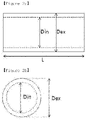
- FIGs. 1a and 1b are mimetic diagrams of a structure. Fig. 1a is given for reference purposes, and Fig 1b . shows an embodiment of the present invention.
- a structure (10) may include a tube (11) having both ends (12) (one shown) open; and a metal (13) formed on an inner surface of the tube (11).
- a lithium metal (14) formed on the metal (13) .
- FIG. 2a and 2b are respectively mimetic diagrams illustrating a longitudinal section ( FIG. 2(a) ) and a transverse section ( FIG. 2(b) ) of the tube in the structure according to one embodiment of the present invention.
- a cavity defined within the tube is a cavity (15).
- an aspect ratio (a) of the longitudinal section of the tube (11) may be more than 1.
- L is a length of the tube (11) and D ex is an outer diameter of the tube (11).
- the length of the tube (11) may be 2 ⁇ m to 25 ⁇ m, preferably 3 ⁇ m to 15 ⁇ m, and more preferably 4 ⁇ m to 10 ⁇ m.
- the length of the tube is less than the above range, it may be difficult to implement the tube having an aspect ratio more than 1 by Equation 1.
- the length of the tube is more than the above range, there may be a problem that the packing density is low and the pores of the electrode become large even after rolling, so that the energy density per cell volume becomes low.
- the outer diameter (D ex ) of the tube (11) may be 0.2 ⁇ m to 2 ⁇ m, preferably 0.3 ⁇ m to 1.2 ⁇ m, more preferably 0.5 ⁇ m to 1 ⁇ m.
- the outer diameter is less than the above range, the volume of the lithium metal (14) contained in the structure (10) is reduced, so that the lithium dendrite inhibiting effect and battery cycle lives are reduced and the specific capacity of the active material and the energy density per weight of the battery become lower.
- the outer diameter is more than the above range, it is difficult to maintain the shape of the tube in the manufacturing process and the tube shape may be broken even during the electrode manufacturing and rolling processes, so that the lithium dendrite inhibiting effect is lowered.
- the actual dimensions of the tube (11), such as length L, outer diameter D ex and inner diameter D in , may be measured with SEM(scanning electron microscope) or TEM(transmission electron microscope).
- the structure (10) has a tube (11) shape having an aspect ratio of more than 1 (a>1) as described above and the tube (11) may include a carbon-based polymer, and therefore, the structure (10) itself may function as an electrical conduction pathway.
- the tube (11) has a cylindrical shape having one or both ends open, and the tube itself may become an electrical conduction pathway, and ion conductivity may be enhanced by liquid electrolyte wetting.
- the sphere When a structure is a hollow type capsule having a sphere shape, the sphere has a closed shape, and thus, it is difficult to impregnate electrolyte liquid compared to a tube shape, to transfer lithium ions into the structure and to control the volume of the lithium metal filled on its inside. In addition, when forming an electrode, its electrical conductivity may decrease due to its sphere shape.
- a shell of the tube (11) may exhibit electrical conductivity, and may also exhibit lithium ion conductivity.
- the shell of the tube (11) may include carbon, and the carbon may be amorphous carbon.
- the tube (11), and in particular the shell of the tube (11), may be porous.
- the thickness of the shell will increase to reinforce the strength.
- the electrolyte can penetrate into the shell, so that the resistance of the battery may be reduced.
- the size of the pores may range from 2 nm to 200 nm, and it is preferred to have a porosity of 0% to 50% for maintaining the strength of the tube.
- the metal (13) may be included in a shape of being formed on an inner surface of the tube (11), and the metal (13) may be included in 0.1% by weight to 25% by weight, preferably 0.1% by weight to 15% by weight and more preferably 0.5% by weight to 10% by weight based on the total weight of the structure (10), that is, the total weight of the tube (11) and the metal (13).
- the weight of the metal (13) When the weight of the metal (13) is less than the range, sites for an electrode active material to bind may not be sufficient, and when the weight is more than the range, the amount of the metal (13) may become excessive resulting in a relative decrease in the amount of an electrode active material to fill, and as a result, the specific capacity of the electrode active material may decrease.
- the metal (13) may be formed on an inner surface of the tube (11) in a particle form, and the metal (13) may be a particle having a particle diameter of 1 nm to 50 nm, preferably 5 nm to 40 nm, and more preferably 10 nm to 30 nm.
- the metal (13) has a particle diameter of less than 1 nm, areas for an electrode active material to bind may not be sufficient, which may not induce smooth growth of the electrode active material, and when the particle diameter is more than 50 nm, areas for metal (13) formation increase, thus, decreasing the specific capacity of the electrode active material.
- the tube (11) may be suitable for supporting an electrode active material.
- the electrode active material may be a positive electrode active material or a negative electrode active material commonly used.
- the positive electrode active material may be an oxide formed with lithium and a transition metal having a structure capable of lithium intercalation, and for example, may be represented by the following Chemical Formula 1.
- Chemical Formula 1 Li a Ni 1-x-y Co x Mn y M b O 2
- M may be any one selected from among transition metals or lanthanide elements, for instance, selected from the group consisting of Al, Cr, Mn, Fe, Mg, La, Ce, Sr, V, Zn and combinations thereof.
- Typical examples of the negative electrode active material may include graphite-based carbon, amorphous carbon such as non-graphitized carbon, crystalline carbon and the like, and may also use metal composite oxides such as Li x Fe 2 O 3 (0 ⁇ x ⁇ 1), Li x WO 2 (0 ⁇ x ⁇ 1) and Sn x Me 1-x Me' y O z (Me: Mn, Fe, Pb, Ge; Me': Al, B, P, Si, elements of group 1, group 2 and group 3 in the periodic table, halogen; 0 ⁇ x ⁇ 1; 1 ⁇ y ⁇ 3; 1 ⁇ z ⁇ 8); lithium metal; lithium alloys; silicon-based alloys; tin-based alloys; metal oxides such as SnO, SnO 2 , PbO, PbO 2 , Pb 2 O 3 , Pb 3 O 4 , Sb 2 O 3 , Sb 3 O 4 , Sb 2 O 3 , GeO, GeO 3 , Bi 2 O 3 , Bi 2 O 4 and Bi 2 O 3
- the metal having a low overvoltage compared to Cu (current collector) when forming the lithium metal may be one or more types selected from the group consisting of Au, Zn, Mg, Ag, Al, Pt, In, Co, Ni, Mn and Si as a metal having a low interfacial energy when reacting with the lithium metal, and the metal having a multiphase with the lithium metal may be Ca as a metal having a plurality of sites capable of reacting with the lithium metal.
- the tube (11) may include a semiconductor element and an oxide of the semiconductor element.
- the oxide of the semiconductor element may include oxides of group 14 semiconductor elements except carbon.
- the oxide of the semiconductor element may include oxides of a Si, Ge or Sn element.
- the oxide of the semiconductor element may include SiO x (herein, 0.3 ⁇ x ⁇ 1.2), GeO y (herein, 0.2 ⁇ y ⁇ 1.1), SnO z (herein, 0.3 ⁇ z ⁇ 1.2) or combinations thereof, and for example, the oxide of the semiconductor element may be SiO x (herein, 0.3 ⁇ x ⁇ 1.2) or GeO y (herein, 0.2 ⁇ y ⁇ 1.1).
- the present invention relates to a structure capable of enhancing battery safety by supporting an electrode active material, and for example, may, when the structure supports lithium metal as a negative electrode active material, prevent a direct reaction between the lithium metal and a liquid electrolyte while preventing the lithium metal from growing in a dendrite form in a negative electrode of a lithium metal battery.
- the present invention relates to a structure (10) including a tube (11) having an inner surface forming a cavity and two ends, wherein one or both ends are open; a metal (13) included on an inner surface of the tube (11); and lithium metal (14) formed on the metal (13) (see, illustratively, FIG. 1b ) .
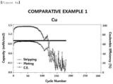
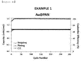
- the cycle efficiency is not good, because even if the lithium dendrite is suppressed, side reactions of the lithium dendrite with the electrolytic solution occur. Therefore, in the development of a battery with a long life of, for instance, 500 cycles or more, it may be more advantageous to apply the structure (10) including the metal (14) to a negative electrode of a lithium metal battery as compared to the structure (10) not including the metal (14).
- an alloy of the metal (13) and the lithium metal (14) may be formed.
- the alloy may be Li x Au, and herein, x may be a real number of 0 ⁇ x ⁇ 3.75.
- a cavity (15, shown in FIGs. 2a and 2b ) inside the tube (11) including the metal (13) may be filled with the lithium metal (14).
- the lithium metal (14) may fill up inside the cavity (15) while growing through bonding to the metal (13), and a volume of the lithium metal (14) filling inside the cavity (15) may be calculated by the following Equation 2 using a volume ratio ( ⁇ ) of the lithium metal with respect to a free volume of the tube (11), which is 0 ⁇ 1.
- ⁇ V Li / V F
- V F ⁇ D in / 2 2 L
- Equation 3 D in is an inner diameter of the tube and L is a length of the tube.
- ⁇ value increases in the 0 ⁇ 1 range, a volume of the lithium metal included in the structure (10) increases, and accordingly, a cycle life of a battery may be enhanced.
- the length of the tube (11) may be 2 ⁇ m to 25 ⁇ m, preferably 3 ⁇ m to 15 ⁇ m, and more preferably 4 ⁇ m to 10 ⁇ m.
- the length of the tube is less than the above range, it may be difficult to implement the tube having an aspect ratio more than 1 by Equation 1.
- the length of the tube is more than the above range, there may be a problem that the packing density is low and the pores of the electrode become large even after rolling, so that the energy density per cell volume becomes low.
- the inner diameter (D in ) of the tube (11) may be 0.1 ⁇ m to 1.8 ⁇ m, preferably 0.2 ⁇ m to 1.1 ⁇ m, more preferably 0.4 ⁇ m to 0.9 ⁇ m.
- the inner diameter is less than the above range, the volume of the lithium metal (14) contained in the structure (10) may be is reduced, so that the lithium dendrite inhibiting effect and battery cycle lives are reduced and the specific capacity of the active material and the energy density per weight of the battery become lower.
- the inner diameter is more than the above range, it is difficult to maintain the shape of the tube in the manufacturing process and the tube shape may be broken even during the electrode manufacturing and rolling processes, so that the lithium dendrite inhibiting effect is lowered.
- Also disclosed is a method for preparing a structure including (S1) forming a tube precursor by electric radiating a metal precursor solution and a carbon-based polymer solution; (S2) first heat treating the tube precursor; and (S3) second heat treating the first heat treated tube precursor, and the method furthers includes (S4) forming lithium metal inside the tube obtained in (S3).
- temperatures of the first heat treatment and the second heat treatment are all different, and the second heat treating temperature may be relatively higher than the first heat treating temperature.
- a tube precursor may be formed by electric radiating a metal precursor solution and a carbon-based polymer solution.
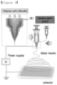
- Electric radiation may be carried out through an electric radiation method using a dual nozzle including inner side and outer side nozzles, and may be carried out in a voltage range of 10 kV to 20 kV and a tip to collector distance (TCD) of 5 cm to 20 cm with steel use stainless (SUS) as a collector using a high pressure electric radiator.
- TCD tip to collector distance
- SUS steel use stainless
- the electric radiation may use electric radiation methods commonly used in the art.
- a dual-nozzle system illustrated in FIG. 3 Adv. Mater., 2010, 22, 496 , herein incorporated by reference
- FIG. 3 Adv. Mater., 2010, 22, 496 , herein incorporated by reference
- a core-shell-shaped tube precursor may be formed by injecting the metal precursor solution and the carbon-based polymer solution to the inner side and the outer side nozzles, respectively, and electric radiating.
- the metal precursor solution may be prepared by dissolving a metal precursor and a polymer in a solvent.
- the metal precursor solution may include the metal precursor in 0.1% by weight to 5% by weight, the polymer in 1% by weight to 20% by weight and the solvent in 75% by weight to 95% by weight based upon the total weight of the metal precursor solution.
- the metal precursor may be one or more types selected from the group consisting of metal-including alkoxides, acetyl acetates, nitrates, oxalates, halides and cyanides, and specifically, the metal may be one or more types selected from the group consisting of Au, Zn, Mg, Ag, Al, Pt, In, Co, Ni, Mn, Si and Ca.
- the precursor of Au may be one or more types selected from the group consisting of HAuCl 4 , HAuCl 4 ⁇ 3H 2 O, HAuCl 4 ⁇ 4H 2 O, AuCl 3 and AuCl.
- the metal performing a role of a seed metal for lithium metal growth may not be sufficiently formed inside the structure, and inside the tube may not be filled with lithium metal to a target level, and when the content is more than 5% by weight, the amount of the formed metal increases with respect to the total weight of the structure, which may relatively reduce the amount of the lithium metal formed inside the structure, and as a result, a cycle life property of a battery may decline.
- the polymer may be one or more types selected from the group consisting of polymethyl methacrylate (PMMA), polyvinyl pyrrolidone (PVP), polyvinyl acetate (PVAc), polyvinyl alcohol (PVA), polystyrene (PS) and polyvinylidene fluoride (PVDF), and polymers capable of being removed at a carbonizing temperature of a carbon-based polymer may be widely used normally.
- PMMA polymethyl methacrylate
- PVP polyvinyl pyrrolidone
- PVAc polyvinyl acetate
- PVA polyvinyl alcohol
- PS polystyrene
- PVDF polyvinylidene fluoride
- the polymer When the polymer is included in less than 1% by weight, forming tube precursor using electric radiation is difficult, and when the content is more than 20% by weight, the polymer remains without being sufficiently removed in the first heat treatment thereby declining battery performance.
- the solvent may be one or more types selected from the group consisting of methylpyrrolidone (NMP), dimethylformamide (DMF), dimethylacetamide (DMAc), dimethyl sulfoxide (DMSO), tetrahydrofuran (THF) and mixtures thereof.
- NMP methylpyrrolidone
- DMF dimethylformamide
- DMAc dimethylacetamide
- DMSO dimethyl sulfoxide
- THF tetrahydrofuran
- the metal precursor solution When the solvent is included in less than 75% by weight, the metal precursor solution may be difficult to prepare, and when the content is more than 95% by weight, the amounts of the metal precursor and the polymer relatively decrease making it difficult to form the metal inside the structure to a target level.
- the carbon-based polymer solution may be prepared by dissolving a carbon-based polymer in a solvent.
- the carbon-based polymer may be one or more types selected from the group consisting of polyacrylonitrile (PAN), polyaniline (PANI), polypyrrole (PPY), polyimide (PI), polybenzimidazole (PBI), polypyrrolidone (Ppy), polyamide (PA), polyamide-imide (PAI), polyaramide, melamine, melamineformaldehyde and fluorine mica. Meanwhile, density of the carbon included in the tube may be from 2.0 g/cm 3 to 2.5 g/cm 3 .
- the carbon-based polymer solution may be prepared by dissolving 1% by weight to 20% by weight of the carbon-based polymer in 80% by weight to 99% by weight of the solvent based upon the total weight of the carbon-based polymer solution.
- the weight of the carbon-based polymer may not be sufficient to form the tube and the tube may not be formed after electric radiation, and when the content is more than 20% by weight, the concentration of the carbon-based polymer solution may be excessively high and electric radiation may not be smoothly progressed.
- the concentration of the carbon-based polymer solution may be excessively high and electric radiation may not be smoothly progressed, and when the content is more than 99% by weight, a tube form may not be formed after electric radiation.
- the solvent used in preparing the metal precursor solution and the carbon-based polymer solution may be the same as or different from each other.
- the tube precursor is first heat treated through heating, and the polymer included in the core of the tube precursor may be removed.
- the heating temperature of the first heat treatment may be from 200°C to 700°C, and the heat treatment may be carried out while raising a temperature.
- a metal may be formed by the polymer included in the core of the tube precursor being removed and the metal precursor being reduced while raising a temperature in the first heat treatment.
- the polymer included in the core of the tube precursor may not be removed and the metal precursor may not be reduced as well, and when the temperature is higher than 700°C, a problem of a metal being formed not only on an inner surface of the tube but on an outer surface of the tube may occur.
- a metal is formed on an inner surface of the tube through a reduction reaction by the heat treatment, and the metal may have a particle form with nano-sized particle sizes of 1 nm to 50 nm.
- the first heat treatment may be carried out under inert atmosphere, and specifically, the inert atmosphere may be formed by one or more types of inert gases selected from the group consisting of Ar, N 2 , He, Ne and Ne.
- the first heat treated tube precursor is second heat treated through heating, and the shell of the tube precursor may be carbonized to form a tube structure including carbon.
- the heating temperature of the second heat treatment may be higher than 700°C and lower than or equal to and 1000°C.
- the second heat treating temperature is 700°C or lower, carbonization may not completely occur, and when the temperature is higher than 1000°C, physical properties of the formed tube structure may decline due to high temperature treatment.
- pores controlled in size can be formed in the tube shell at a heating temperature of about 800°C within a heating temperature range of 700 to 1000°C.
- the pores become smaller as the temperature is higher than 800°C and the pores become larger as the heating temperature is lower than 800°C. Therefore, the pore size can be controlled by controlling the heating temperature within the heating temperature range.
- lithium metal is formed inside the tube structure.
- a method of forming lithium metal inside the tube structure may use one type of method selected from the group consisting of electroplating, electroless plating and deposition, however, the method is not limited thereto, and methods capable of forming lithium metal inside the tube structure and filling the tube structure with the lithium metal may be widely used.
- a lithium source for forming the lithium metal may be one or more types selected from the group consisting of lithium salts, lithium ingot and lithium metal oxides, but is not limited thereto as long as it is a compound capable of providing lithium ions.
- the lithium salt may be one or more types selected from the group consisting of LiPF 6 , LiClO 4 , LiAsF 6 , LiBF 4 , LiSbF 6 , LiAl0 4 , LiAlCl 4 , LiCF 3 SO 3 , LiC 4 F 9 SO 3 , LiN(C 2 F 5 SO 3 ) 2 , LiN(C 2 F 5 SO 2 ) 2 , LiN(CF 3 SO 2 ) 2 . LiN(CaF 2a+1 SO 2 )(CbF 2b+1 SO 2 ) (wherein a and b are natural numbers, and preferably 1 ⁇ a ⁇ 20 and 1 ⁇ b ⁇ 20), LiCl, LiI and LiB (C 2 O 4 ) 2 .
- the lithium metal-supported structure prepared as above may be used as a negative electrode active material of a lithium metal battery, and may be capable of solving problems of lithium metal dendrite formation, a chronic problem of existing lithium metal batteries, and interfacial instability caused therefrom.
- a metal precursor solution was prepared by dissolving 0.5% by weight of HAuCl 4 (a metal precursor), 11% by weight of PMMA (a polymer), in 88.5% by weight of a solvent.
- a solvent a mixed solvent mixing dimethylformamide (DMF) and acetone in a weight ratio of 85:15 was used.
- a carbon-based polymer solution was prepared by dissolving 13% by weight of PAN (a carbon-based polymer), in 87% by weight of dimethylformamide (DMF) (a solvent).
- DMF dimethylformamide
- the metal precursor solution and the carbon-based polymer solution were introduced to an inner nozzle and an outer nozzle, respectively, of a dual-nozzle system including an inner nozzle and an outer nozzle ( Adv. Mater., 2010, 22, 496 , herein incorporated by reference), and electric radiated to form a tube precursor.
- the condition during electric radiation was set as follows.
- the tube precursor was heat treated in a 280°C furnace to remove PMMA included in a core of the tube precursor, and the temperature was raised to reduce HAuCl 4 and form Au particles on an inner surface of the tube precursor shell.
- PAN of the tube precursor was carbonized at 850°C to form a tube structure having Au formed on the inner surface thereof.
- Lithium metal was formed inside the tube structure having Au formed on the inner surface of Reference Example 1 through electroplating.
- LiClO 4 (a lithium salt) was used as a lithium source.
- the electroplating was carried out by flowing a current on a lithium half-cell manufactured using a method as below with currently density of 1 mA/cm 2 .
- LiTFSI lithium bis-trifluoromethanesulfonimide
- DME 1,2-dimethoxyethane
- DOL 1,3-dioxolane
- a polyethylene separator was used as a separator.
- a lithium half-cell was manufactured using the prepared negative electrode, the polyethylene separator and the liquid electrolyte.
- a tube-shaped structure was prepared in the same manner as in Example 1, except that a metal is not included on an inner surface of the tube.
- LiTFSI lithium bis-trifluoromethanesulfonimide
- DME 1,2-dimethoxyethane
- DOL 1,3-dioxolane
- a polyethylene separator was used as a separator.
- a lithium half-cell was manufactured using the prepared negative electrode, the polyethylene separator and the liquid electrolyte.
- FIGs. 4a to 4c show graphs of charge and discharge test results for the lithium half-cells manufactured using the structures of the reference examples and the comparative examples.
- FIG. 5 shows transmission electron microscope (TEM) images observing form changes of the lithium half-cell manufactured using the structure of Reference Example 1 before and after charge and discharge (Pristine: before charge and discharge; 20 th D: after 20 th discharge; 20 th C: after 20 th charge).
- TEM transmission electron microscope
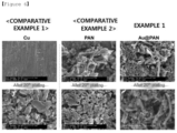
- FIG. 6 shows scanning electron microscope (SEM) images observing a form of lithium metal growth when charging and discharging the lithium half-cells manufactured using the structures of the examples and the comparative examples.
Landscapes
- Chemical & Material Sciences (AREA)
- Chemical Kinetics & Catalysis (AREA)
- Electrochemistry (AREA)
- General Chemical & Material Sciences (AREA)
- Engineering & Computer Science (AREA)
- Materials Engineering (AREA)
- Ceramic Engineering (AREA)
- Composite Materials (AREA)
- Manufacturing & Machinery (AREA)
- Battery Electrode And Active Subsutance (AREA)
- Secondary Cells (AREA)
- Buildings Adapted To Withstand Abnormal External Influences (AREA)
Applications Claiming Priority (3)
| Application Number | Priority Date | Filing Date | Title |
|---|---|---|---|
| KR20170033414 | 2017-03-16 | ||
| KR1020180030410A KR102115601B1 (ko) | 2017-03-16 | 2018-03-15 | 구조체 |
| PCT/KR2018/003077 WO2018169337A1 (ko) | 2017-03-16 | 2018-03-16 | 구조체 |
Publications (3)
| Publication Number | Publication Date |
|---|---|
| EP3486982A1 EP3486982A1 (en) | 2019-05-22 |
| EP3486982A4 EP3486982A4 (en) | 2019-10-23 |
| EP3486982B1 true EP3486982B1 (en) | 2023-02-08 |
Family
ID=63877546
Family Applications (1)
| Application Number | Title | Priority Date | Filing Date |
|---|---|---|---|
| EP18767599.6A Active EP3486982B1 (en) | 2017-03-16 | 2018-03-16 | Structure |
Country Status (8)
| Country | Link |
|---|---|
| US (1) | US11251438B2 (pl) |
| EP (1) | EP3486982B1 (pl) |
| JP (1) | JP6765699B2 (pl) |
| KR (1) | KR102115601B1 (pl) |
| CN (1) | CN109792057B (pl) |
| ES (1) | ES2940317T3 (pl) |
| HU (1) | HUE061526T2 (pl) |
| PL (1) | PL3486982T3 (pl) |
Families Citing this family (1)
| Publication number | Priority date | Publication date | Assignee | Title |
|---|---|---|---|---|
| KR102081772B1 (ko) * | 2017-03-16 | 2020-02-26 | 주식회사 엘지화학 | 전극 및 이를 포함하는 리튬 이차전지 |
Family Cites Families (26)
| Publication number | Priority date | Publication date | Assignee | Title |
|---|---|---|---|---|
| JPH0945312A (ja) * | 1995-07-31 | 1997-02-14 | Matsushita Electric Ind Co Ltd | 非水電解液二次電池用負極とこれを用いた電池 |
| JP2005174755A (ja) * | 2003-12-11 | 2005-06-30 | Nissan Motor Co Ltd | 電極触媒、該触媒を用いた触媒担持電極およびmea |
| KR100561856B1 (ko) | 2004-01-07 | 2006-03-16 | 삼성에스디아이 주식회사 | 촉매 담체용 짧은 탄소나노튜브, 상기 탄소나노튜브를 이용한 탄소나노튜브 담지 촉매 및 이를 채용한 연료전지 |
| JP4625953B2 (ja) * | 2005-06-02 | 2011-02-02 | 国立大学法人 筑波大学 | カーボンナノチューブに担持した金属触媒及びその作製方法 |
| KR100903503B1 (ko) * | 2007-11-02 | 2009-06-17 | 삼성에스디아이 주식회사 | 음극활물질, 그 제조방법 및 그 음극활물질을 구비한 리튬이차전지 |
| CN101521273B (zh) * | 2009-03-26 | 2010-12-29 | 上海大学 | 一种制备锡-碳/核-壳纳米粒子完全填充碳纳米管复合负极材料的原位合成方法 |
| US8574767B2 (en) * | 2009-05-18 | 2013-11-05 | The Johns Hopkins University | Thin film electrodes including metal tubes filled with active material and battery cells, and methods of fabrication |
| KR101159226B1 (ko) | 2009-09-30 | 2012-06-25 | 국립대학법인 울산과학기술대학교 산학협력단 | 리튬 이차 전지용 음극 활물질, 이의 제조 방법 및 이를 포함하는 리튬 이차 전지 |
| KR101155909B1 (ko) | 2010-01-07 | 2012-06-20 | 삼성에스디아이 주식회사 | 리튬 이차 전지용 음극 활물질, 이의 제조 방법 및 이를 포함하는 리튬 이차 전지 |
| JP2012033423A (ja) * | 2010-08-02 | 2012-02-16 | Sumitomo Electric Ind Ltd | 金属多孔体およびその製造方法、それを用いた電池 |
| CN102916198B (zh) * | 2011-08-05 | 2015-03-11 | 清华大学 | 燃料电池膜电极 |
| EP2748882A4 (en) | 2011-09-12 | 2015-03-18 | Univ Leland Stanford Junior | CAPSUED SWEAT CATALYSIS FOR RECHARGEABLE LITHIUM BATTERIES |
| KR20140138806A (ko) * | 2012-03-02 | 2014-12-04 | 코넬 유니버시티 | 나노섬유들을 포함하는 리튬 이온 배터리들 |
| GB2500611A (en) * | 2012-03-26 | 2013-10-02 | Cambridge Entpr Ltd | Powder comprising carbon nanostructures and method of preparation |
| JP5919138B2 (ja) * | 2012-08-22 | 2016-05-18 | 株式会社ノリタケカンパニーリミテド | Pt担持マイクロチューブとその製造方法 |
| TWI440883B (zh) | 2012-08-30 | 2014-06-11 | Largan Precision Co Ltd | 結像鏡頭 |
| CN103022451B (zh) * | 2012-12-24 | 2015-03-25 | 中国科学院金属研究所 | 一种纳米硅颗粒填充碳纳米管复合物及其制备方法和应用 |
| KR101477782B1 (ko) * | 2013-04-11 | 2014-12-31 | 한국과학기술원 | 고분자 나노섬유, 알루미늄 박막, 탄소나노튜브 및 유황의 복합체를 이용한 리튬-황 이차전지용 전극 및 그 제조 방법 |
| KR101666871B1 (ko) | 2013-04-23 | 2016-10-24 | 삼성에스디아이 주식회사 | 양극 활물질 및 이의 제조 방법, 그리고 상기 양극 활물질을 포함하는 리튬 이차 전지 |
| KR101599600B1 (ko) | 2014-02-06 | 2016-03-03 | 한국교통대학교산학협력단 | 다공성 중공구조의 나노섬유 형태를 갖는 리튬이차전지용 양극활물질의 제조방법 및 그 제조방법에 의해 제조된 양극활물질 및 그 양극활물질을 포함한 리튬이차전지 |
| DE102015205443B4 (de) * | 2014-04-01 | 2021-05-27 | Leibniz-Institut Für Festkörper- Und Werkstoffforschung Dresden E.V. | Anodenmaterial für Lithium-Ionen-Batterien |
| WO2015190898A1 (ko) | 2014-06-13 | 2015-12-17 | 주식회사 엘지화학 | 리튬 전극 및 이를 포함하는 리튬 이차전지 |
| CN104112847B (zh) * | 2014-07-03 | 2017-02-01 | 奇瑞汽车股份有限公司 | 一种硅基负极材料及其方法 |
| KR20160064899A (ko) | 2014-11-28 | 2016-06-08 | 삼성에스디아이 주식회사 | 음극 활물질, 이를 포함하는 리튬 전지, 및 상기 음극 활물질의 제조방법 |
| KR101719048B1 (ko) | 2015-01-20 | 2017-03-23 | 포항공과대학교 산학협력단 | 리튬-황 전지용 양극 활물질 및 그 제조 방법 |
| DE102015005443A1 (de) | 2015-04-28 | 2016-12-01 | Jinghong Chen | Fördergutstracking durch Kamera |
-
2018
- 2018-03-15 KR KR1020180030410A patent/KR102115601B1/ko active Active
- 2018-03-16 CN CN201880003657.XA patent/CN109792057B/zh active Active
- 2018-03-16 EP EP18767599.6A patent/EP3486982B1/en active Active
- 2018-03-16 PL PL18767599.6T patent/PL3486982T3/pl unknown
- 2018-03-16 JP JP2019528013A patent/JP6765699B2/ja active Active
- 2018-03-16 HU HUE18767599A patent/HUE061526T2/hu unknown
- 2018-03-16 ES ES18767599T patent/ES2940317T3/es active Active
-
2019
- 2019-02-06 US US16/268,925 patent/US11251438B2/en active Active
Also Published As
| Publication number | Publication date |
|---|---|
| US20190173095A1 (en) | 2019-06-06 |
| US11251438B2 (en) | 2022-02-15 |
| CN109792057B (zh) | 2022-07-19 |
| KR102115601B1 (ko) | 2020-05-26 |
| JP6765699B2 (ja) | 2020-10-07 |
| HUE061526T2 (hu) | 2023-07-28 |
| PL3486982T3 (pl) | 2023-04-11 |
| CN109792057A (zh) | 2019-05-21 |
| EP3486982A1 (en) | 2019-05-22 |
| KR20180106947A (ko) | 2018-10-01 |
| EP3486982A4 (en) | 2019-10-23 |
| JP2019525443A (ja) | 2019-09-05 |
| ES2940317T3 (es) | 2023-05-05 |
Similar Documents
| Publication | Publication Date | Title |
|---|---|---|
| EP2863455B1 (en) | Porous silicon-based negative electrode active material, method for preparing same, and lithium secondary battery comprising same | |
| EP4109593A1 (en) | Anode and secondary battery comprising same | |
| US11380888B2 (en) | Electrode and lithium secondary battery comprising same | |
| EP4300628A1 (en) | Positive electrode material, method for preparing same, and lithium secondary battery comprising same | |
| KR102623063B1 (ko) | 리튬 이차전지용 복합음극 및 이를 포함하는 리튬 이차전지 | |
| KR20230010171A (ko) | 리튬 이차 전지용 음극, 리튬 이차 전지용 음극의 제조 방법 및 음극을 포함하는 리튬 이차 전지 | |
| KR102580237B1 (ko) | 복합 전극활물질, 이를 포함하는 리튬전지, 및 상기 복합 전극활물질의 제조방법 | |
| EP3486982B1 (en) | Structure | |
| US11459672B2 (en) | Method for manufacturing structure | |
| EP4407709A1 (en) | Cathode material, cathode comprising same and lithium secondary battery | |
| KR102183659B1 (ko) | 전극의 제조방법 | |
| JP4021651B2 (ja) | リチウムイオン二次電池用正極板およびそれを用いたリチウムイオン二次電池 | |
| EP4456174A2 (en) | All-solid secondary battery | |
| EP4576261A1 (en) | Cathode material, cathode comprising same, and lithium secondary battery | |
| EP4715906A1 (en) | Positive electrode active material, and positive electrode and lithium secondary battery comprising same | |
| EP4571879A1 (en) | Positive electrode active material, manufacturing method therefor, and positive electrode and lithium secondary battery comprising same | |
| EP4435882A1 (en) | Positive electrode for lithium secondary battery, and lithium secondary battery comprising same | |
| EP4685911A1 (en) | All-solid-state secondary battery | |
| KR20250037117A (ko) | 리튬 이차 전지 | |
| KR20250037111A (ko) | 리튬 이차 전지의 제조 방법 및 리튬 이차 전지 | |
| EP4685869A1 (en) | Positive electrode material, and positive electrode slurry, positive electrode, and lithium secondary battery comprising same | |
| KR20250031989A (ko) | 음극 활물질, 음극 활물질의 제조 방법, 음극 조성물, 이를 포함하는 리튬 이차 전지용 음극 및 음극을 포함하는 리튬 이차 전지 | |
| KR20250000270A (ko) | 리튬 이차 전지의 제조 방법 및 리튬 이차 전지 | |
| EP4560733A1 (en) | Cathode active material, cathode comprising same, and lithium secondary battery |
Legal Events
| Date | Code | Title | Description |
|---|---|---|---|
| STAA | Information on the status of an ep patent application or granted ep patent |
Free format text: STATUS: THE INTERNATIONAL PUBLICATION HAS BEEN MADE |
|
| PUAI | Public reference made under article 153(3) epc to a published international application that has entered the european phase |
Free format text: ORIGINAL CODE: 0009012 |
|
| STAA | Information on the status of an ep patent application or granted ep patent |
Free format text: STATUS: REQUEST FOR EXAMINATION WAS MADE |
|
| 17P | Request for examination filed |
Effective date: 20190213 |
|
| AK | Designated contracting states |
Kind code of ref document: A1 Designated state(s): AL AT BE BG CH CY CZ DE DK EE ES FI FR GB GR HR HU IE IS IT LI LT LU LV MC MK MT NL NO PL PT RO RS SE SI SK SM TR |
|
| AX | Request for extension of the european patent |
Extension state: BA ME |
|
| A4 | Supplementary search report drawn up and despatched |
Effective date: 20190925 |
|
| RIC1 | Information provided on ipc code assigned before grant |
Ipc: H01M 10/052 20100101ALI20190919BHEP Ipc: H01M 4/38 20060101ALI20190919BHEP Ipc: H01M 4/134 20100101ALI20190919BHEP Ipc: H01M 4/76 20060101AFI20190919BHEP Ipc: H01M 4/66 20060101ALI20190919BHEP |
|
| DAV | Request for validation of the european patent (deleted) | ||
| DAX | Request for extension of the european patent (deleted) | ||
| RAP1 | Party data changed (applicant data changed or rights of an application transferred) |
Owner name: KOREA ADVANCED INSTITUTE OF SCIENCE AND TECHNOLOGY Owner name: LG ENERGY SOLUTION, LTD. |
|
| RAP3 | Party data changed (applicant data changed or rights of an application transferred) |
Owner name: KOREA ADVANCED INSTITUTE OF SCIENCE AND TECHNOLOGY Owner name: LG ENERGY SOLUTION, LTD. |
|
| GRAP | Despatch of communication of intention to grant a patent |
Free format text: ORIGINAL CODE: EPIDOSNIGR1 |
|
| STAA | Information on the status of an ep patent application or granted ep patent |
Free format text: STATUS: GRANT OF PATENT IS INTENDED |
|
| INTG | Intention to grant announced |
Effective date: 20220922 |
|
| GRAS | Grant fee paid |
Free format text: ORIGINAL CODE: EPIDOSNIGR3 |
|
| GRAA | (expected) grant |
Free format text: ORIGINAL CODE: 0009210 |
|
| STAA | Information on the status of an ep patent application or granted ep patent |
Free format text: STATUS: THE PATENT HAS BEEN GRANTED |
|
| AK | Designated contracting states |
Kind code of ref document: B1 Designated state(s): AL AT BE BG CH CY CZ DE DK EE ES FI FR GB GR HR HU IE IS IT LI LT LU LV MC MK MT NL NO PL PT RO RS SE SI SK SM TR |
|
| REG | Reference to a national code |
Ref country code: GB Ref legal event code: FG4D |
|
| REG | Reference to a national code |
Ref country code: CH Ref legal event code: EP Ref country code: AT Ref legal event code: REF Ref document number: 1547664 Country of ref document: AT Kind code of ref document: T Effective date: 20230215 |
|
| REG | Reference to a national code |
Ref country code: DE Ref legal event code: R096 Ref document number: 602018046015 Country of ref document: DE |
|
| REG | Reference to a national code |
Ref country code: IE Ref legal event code: FG4D |
|
| REG | Reference to a national code |
Ref country code: SE Ref legal event code: TRGR |
|
| REG | Reference to a national code |
Ref country code: ES Ref legal event code: FG2A Ref document number: 2940317 Country of ref document: ES Kind code of ref document: T3 Effective date: 20230505 |
|
| REG | Reference to a national code |
Ref country code: LT Ref legal event code: MG9D |
|
| P01 | Opt-out of the competence of the unified patent court (upc) registered |
Effective date: 20230420 |
|
| REG | Reference to a national code |
Ref country code: NL Ref legal event code: MP Effective date: 20230208 |
|
| REG | Reference to a national code |
Ref country code: AT Ref legal event code: MK05 Ref document number: 1547664 Country of ref document: AT Kind code of ref document: T Effective date: 20230208 |
|
| REG | Reference to a national code |
Ref country code: HU Ref legal event code: AG4A Ref document number: E061526 Country of ref document: HU |
|
| PG25 | Lapsed in a contracting state [announced via postgrant information from national office to epo] |
Ref country code: RS Free format text: LAPSE BECAUSE OF FAILURE TO SUBMIT A TRANSLATION OF THE DESCRIPTION OR TO PAY THE FEE WITHIN THE PRESCRIBED TIME-LIMIT Effective date: 20230208 Ref country code: PT Free format text: LAPSE BECAUSE OF FAILURE TO SUBMIT A TRANSLATION OF THE DESCRIPTION OR TO PAY THE FEE WITHIN THE PRESCRIBED TIME-LIMIT Effective date: 20230609 Ref country code: NO Free format text: LAPSE BECAUSE OF FAILURE TO SUBMIT A TRANSLATION OF THE DESCRIPTION OR TO PAY THE FEE WITHIN THE PRESCRIBED TIME-LIMIT Effective date: 20230508 Ref country code: NL Free format text: LAPSE BECAUSE OF FAILURE TO SUBMIT A TRANSLATION OF THE DESCRIPTION OR TO PAY THE FEE WITHIN THE PRESCRIBED TIME-LIMIT Effective date: 20230208 Ref country code: LV Free format text: LAPSE BECAUSE OF FAILURE TO SUBMIT A TRANSLATION OF THE DESCRIPTION OR TO PAY THE FEE WITHIN THE PRESCRIBED TIME-LIMIT Effective date: 20230208 Ref country code: LT Free format text: LAPSE BECAUSE OF FAILURE TO SUBMIT A TRANSLATION OF THE DESCRIPTION OR TO PAY THE FEE WITHIN THE PRESCRIBED TIME-LIMIT Effective date: 20230208 Ref country code: HR Free format text: LAPSE BECAUSE OF FAILURE TO SUBMIT A TRANSLATION OF THE DESCRIPTION OR TO PAY THE FEE WITHIN THE PRESCRIBED TIME-LIMIT Effective date: 20230208 Ref country code: AT Free format text: LAPSE BECAUSE OF FAILURE TO SUBMIT A TRANSLATION OF THE DESCRIPTION OR TO PAY THE FEE WITHIN THE PRESCRIBED TIME-LIMIT Effective date: 20230208 |
|
| PG25 | Lapsed in a contracting state [announced via postgrant information from national office to epo] |
Ref country code: IS Free format text: LAPSE BECAUSE OF FAILURE TO SUBMIT A TRANSLATION OF THE DESCRIPTION OR TO PAY THE FEE WITHIN THE PRESCRIBED TIME-LIMIT Effective date: 20230608 Ref country code: GR Free format text: LAPSE BECAUSE OF FAILURE TO SUBMIT A TRANSLATION OF THE DESCRIPTION OR TO PAY THE FEE WITHIN THE PRESCRIBED TIME-LIMIT Effective date: 20230509 Ref country code: FI Free format text: LAPSE BECAUSE OF FAILURE TO SUBMIT A TRANSLATION OF THE DESCRIPTION OR TO PAY THE FEE WITHIN THE PRESCRIBED TIME-LIMIT Effective date: 20230208 |
|
| PG25 | Lapsed in a contracting state [announced via postgrant information from national office to epo] |
Ref country code: SM Free format text: LAPSE BECAUSE OF FAILURE TO SUBMIT A TRANSLATION OF THE DESCRIPTION OR TO PAY THE FEE WITHIN THE PRESCRIBED TIME-LIMIT Effective date: 20230208 Ref country code: RO Free format text: LAPSE BECAUSE OF FAILURE TO SUBMIT A TRANSLATION OF THE DESCRIPTION OR TO PAY THE FEE WITHIN THE PRESCRIBED TIME-LIMIT Effective date: 20230208 Ref country code: EE Free format text: LAPSE BECAUSE OF FAILURE TO SUBMIT A TRANSLATION OF THE DESCRIPTION OR TO PAY THE FEE WITHIN THE PRESCRIBED TIME-LIMIT Effective date: 20230208 Ref country code: DK Free format text: LAPSE BECAUSE OF FAILURE TO SUBMIT A TRANSLATION OF THE DESCRIPTION OR TO PAY THE FEE WITHIN THE PRESCRIBED TIME-LIMIT Effective date: 20230208 Ref country code: CZ Free format text: LAPSE BECAUSE OF FAILURE TO SUBMIT A TRANSLATION OF THE DESCRIPTION OR TO PAY THE FEE WITHIN THE PRESCRIBED TIME-LIMIT Effective date: 20230208 |
|
| REG | Reference to a national code |
Ref country code: CH Ref legal event code: PL |
|
| REG | Reference to a national code |
Ref country code: DE Ref legal event code: R097 Ref document number: 602018046015 Country of ref document: DE |
|
| PG25 | Lapsed in a contracting state [announced via postgrant information from national office to epo] |
Ref country code: SK Free format text: LAPSE BECAUSE OF FAILURE TO SUBMIT A TRANSLATION OF THE DESCRIPTION OR TO PAY THE FEE WITHIN THE PRESCRIBED TIME-LIMIT Effective date: 20230208 |
|
| REG | Reference to a national code |
Ref country code: BE Ref legal event code: MM Effective date: 20230331 |
|
| PLBE | No opposition filed within time limit |
Free format text: ORIGINAL CODE: 0009261 |
|
| STAA | Information on the status of an ep patent application or granted ep patent |
Free format text: STATUS: NO OPPOSITION FILED WITHIN TIME LIMIT |
|
| PG25 | Lapsed in a contracting state [announced via postgrant information from national office to epo] |
Ref country code: LU Free format text: LAPSE BECAUSE OF NON-PAYMENT OF DUE FEES Effective date: 20230316 |
|
| 26N | No opposition filed |
Effective date: 20231109 |
|
| PG25 | Lapsed in a contracting state [announced via postgrant information from national office to epo] |
Ref country code: MC Free format text: LAPSE BECAUSE OF FAILURE TO SUBMIT A TRANSLATION OF THE DESCRIPTION OR TO PAY THE FEE WITHIN THE PRESCRIBED TIME-LIMIT Effective date: 20230208 |
|
| REG | Reference to a national code |
Ref country code: IE Ref legal event code: MM4A |
|
| PG25 | Lapsed in a contracting state [announced via postgrant information from national office to epo] |
Ref country code: SI Free format text: LAPSE BECAUSE OF FAILURE TO SUBMIT A TRANSLATION OF THE DESCRIPTION OR TO PAY THE FEE WITHIN THE PRESCRIBED TIME-LIMIT Effective date: 20230208 Ref country code: MC Free format text: LAPSE BECAUSE OF FAILURE TO SUBMIT A TRANSLATION OF THE DESCRIPTION OR TO PAY THE FEE WITHIN THE PRESCRIBED TIME-LIMIT Effective date: 20230208 Ref country code: LI Free format text: LAPSE BECAUSE OF NON-PAYMENT OF DUE FEES Effective date: 20230331 Ref country code: IE Free format text: LAPSE BECAUSE OF NON-PAYMENT OF DUE FEES Effective date: 20230316 Ref country code: CH Free format text: LAPSE BECAUSE OF NON-PAYMENT OF DUE FEES Effective date: 20230331 |
|
| PG25 | Lapsed in a contracting state [announced via postgrant information from national office to epo] |
Ref country code: BE Free format text: LAPSE BECAUSE OF NON-PAYMENT OF DUE FEES Effective date: 20230331 |
|
| PG25 | Lapsed in a contracting state [announced via postgrant information from national office to epo] |
Ref country code: IT Free format text: LAPSE BECAUSE OF FAILURE TO SUBMIT A TRANSLATION OF THE DESCRIPTION OR TO PAY THE FEE WITHIN THE PRESCRIBED TIME-LIMIT Effective date: 20230208 |
|
| PG25 | Lapsed in a contracting state [announced via postgrant information from national office to epo] |
Ref country code: BG Free format text: LAPSE BECAUSE OF FAILURE TO SUBMIT A TRANSLATION OF THE DESCRIPTION OR TO PAY THE FEE WITHIN THE PRESCRIBED TIME-LIMIT Effective date: 20230208 |
|
| PG25 | Lapsed in a contracting state [announced via postgrant information from national office to epo] |
Ref country code: BG Free format text: LAPSE BECAUSE OF FAILURE TO SUBMIT A TRANSLATION OF THE DESCRIPTION OR TO PAY THE FEE WITHIN THE PRESCRIBED TIME-LIMIT Effective date: 20230208 |
|
| PGFP | Annual fee paid to national office [announced via postgrant information from national office to epo] |
Ref country code: DE Payment date: 20250220 Year of fee payment: 8 |
|
| PGFP | Annual fee paid to national office [announced via postgrant information from national office to epo] |
Ref country code: HU Payment date: 20250321 Year of fee payment: 8 |
|
| PGFP | Annual fee paid to national office [announced via postgrant information from national office to epo] |
Ref country code: SE Payment date: 20250220 Year of fee payment: 8 |
|
| PGFP | Annual fee paid to national office [announced via postgrant information from national office to epo] |
Ref country code: FR Payment date: 20250221 Year of fee payment: 8 Ref country code: PL Payment date: 20250221 Year of fee payment: 8 |
|
| PGFP | Annual fee paid to national office [announced via postgrant information from national office to epo] |
Ref country code: GB Payment date: 20250224 Year of fee payment: 8 |
|
| PGFP | Annual fee paid to national office [announced via postgrant information from national office to epo] |
Ref country code: ES Payment date: 20250408 Year of fee payment: 8 |
|
| PG25 | Lapsed in a contracting state [announced via postgrant information from national office to epo] |
Ref country code: CY Free format text: LAPSE BECAUSE OF FAILURE TO SUBMIT A TRANSLATION OF THE DESCRIPTION OR TO PAY THE FEE WITHIN THE PRESCRIBED TIME-LIMIT; INVALID AB INITIO Effective date: 20180316 |
|
| PG25 | Lapsed in a contracting state [announced via postgrant information from national office to epo] |
Ref country code: TR Free format text: LAPSE BECAUSE OF FAILURE TO SUBMIT A TRANSLATION OF THE DESCRIPTION OR TO PAY THE FEE WITHIN THE PRESCRIBED TIME-LIMIT Effective date: 20230208 |