EP3486419B1 - Mitnehmer und fahrzeugfensterheber - Google Patents
Mitnehmer und fahrzeugfensterheber Download PDFInfo
- Publication number
- EP3486419B1 EP3486419B1 EP18204363.8A EP18204363A EP3486419B1 EP 3486419 B1 EP3486419 B1 EP 3486419B1 EP 18204363 A EP18204363 A EP 18204363A EP 3486419 B1 EP3486419 B1 EP 3486419B1
- Authority
- EP
- European Patent Office
- Prior art keywords
- guide
- driver
- carrier
- vehicle window
- traction means
- Prior art date
- Legal status (The legal status is an assumption and is not a legal conclusion. Google has not performed a legal analysis and makes no representation as to the accuracy of the status listed.)
- Active
Links
Images


Classifications
-
- E—FIXED CONSTRUCTIONS
- E05—LOCKS; KEYS; WINDOW OR DOOR FITTINGS; SAFES
- E05F—DEVICES FOR MOVING WINGS INTO OPEN OR CLOSED POSITION; CHECKS FOR WINGS; WING FITTINGS NOT OTHERWISE PROVIDED FOR, CONCERNED WITH THE FUNCTIONING OF THE WING
- E05F11/00—Man-operated mechanisms for operating wings, including those which also operate the fastening
- E05F11/38—Man-operated mechanisms for operating wings, including those which also operate the fastening for sliding windows, e.g. vehicle windows, to be opened or closed by vertical movement
- E05F11/48—Man-operated mechanisms for operating wings, including those which also operate the fastening for sliding windows, e.g. vehicle windows, to be opened or closed by vertical movement operated by cords or chains or other flexible elongated pulling elements, e.g. tapes
- E05F11/481—Man-operated mechanisms for operating wings, including those which also operate the fastening for sliding windows, e.g. vehicle windows, to be opened or closed by vertical movement operated by cords or chains or other flexible elongated pulling elements, e.g. tapes for vehicle windows
- E05F11/483—Man-operated mechanisms for operating wings, including those which also operate the fastening for sliding windows, e.g. vehicle windows, to be opened or closed by vertical movement operated by cords or chains or other flexible elongated pulling elements, e.g. tapes for vehicle windows by cables
-
- E—FIXED CONSTRUCTIONS
- E05—LOCKS; KEYS; WINDOW OR DOOR FITTINGS; SAFES
- E05F—DEVICES FOR MOVING WINGS INTO OPEN OR CLOSED POSITION; CHECKS FOR WINGS; WING FITTINGS NOT OTHERWISE PROVIDED FOR, CONCERNED WITH THE FUNCTIONING OF THE WING
- E05F11/00—Man-operated mechanisms for operating wings, including those which also operate the fastening
- E05F11/38—Man-operated mechanisms for operating wings, including those which also operate the fastening for sliding windows, e.g. vehicle windows, to be opened or closed by vertical movement
- E05F11/382—Man-operated mechanisms for operating wings, including those which also operate the fastening for sliding windows, e.g. vehicle windows, to be opened or closed by vertical movement for vehicle windows
- E05F11/385—Fixing of window glass to the carrier of the operating mechanism
-
- E—FIXED CONSTRUCTIONS
- E05—LOCKS; KEYS; WINDOW OR DOOR FITTINGS; SAFES
- E05D—HINGES OR SUSPENSION DEVICES FOR DOORS, WINDOWS OR WINGS
- E05D15/00—Suspension arrangements for wings
- E05D15/16—Suspension arrangements for wings for wings sliding vertically more or less in their own plane
-
- E—FIXED CONSTRUCTIONS
- E05—LOCKS; KEYS; WINDOW OR DOOR FITTINGS; SAFES
- E05D—HINGES OR SUSPENSION DEVICES FOR DOORS, WINDOWS OR WINGS
- E05D15/00—Suspension arrangements for wings
- E05D15/16—Suspension arrangements for wings for wings sliding vertically more or less in their own plane
- E05D15/165—Details, e.g. sliding or rolling guides
-
- E—FIXED CONSTRUCTIONS
- E05—LOCKS; KEYS; WINDOW OR DOOR FITTINGS; SAFES
- E05F—DEVICES FOR MOVING WINGS INTO OPEN OR CLOSED POSITION; CHECKS FOR WINGS; WING FITTINGS NOT OTHERWISE PROVIDED FOR, CONCERNED WITH THE FUNCTIONING OF THE WING
- E05F7/00—Accessories for wings not provided for in other groups of this subclass
- E05F7/04—Arrangements affording protection against rattling
-
- B—PERFORMING OPERATIONS; TRANSPORTING
- B60—VEHICLES IN GENERAL
- B60J—WINDOWS, WINDSCREENS, NON-FIXED ROOFS, DOORS, OR SIMILAR DEVICES FOR VEHICLES; REMOVABLE EXTERNAL PROTECTIVE COVERINGS SPECIALLY ADAPTED FOR VEHICLES
- B60J1/00—Windows; Windscreens; Accessories therefor
- B60J1/08—Windows; Windscreens; Accessories therefor arranged at vehicle sides
- B60J1/12—Windows; Windscreens; Accessories therefor arranged at vehicle sides adjustable
- B60J1/16—Windows; Windscreens; Accessories therefor arranged at vehicle sides adjustable slidable
- B60J1/17—Windows; Windscreens; Accessories therefor arranged at vehicle sides adjustable slidable vertically
-
- E—FIXED CONSTRUCTIONS
- E05—LOCKS; KEYS; WINDOW OR DOOR FITTINGS; SAFES
- E05Y—INDEXING SCHEME ASSOCIATED WITH SUBCLASSES E05D AND E05F, RELATING TO CONSTRUCTION ELEMENTS, ELECTRIC CONTROL, POWER SUPPLY, POWER SIGNAL OR TRANSMISSION, USER INTERFACES, MOUNTING OR COUPLING, DETAILS, ACCESSORIES, AUXILIARY OPERATIONS NOT OTHERWISE PROVIDED FOR, APPLICATION THEREOF
- E05Y2201/00—Constructional elements; Accessories therefor
- E05Y2201/60—Suspension or transmission members; Accessories therefor
- E05Y2201/606—Accessories therefor
- E05Y2201/61—Cooperation between suspension or transmission members
- E05Y2201/612—Cooperation between suspension or transmission members between carriers and rails
-
- E—FIXED CONSTRUCTIONS
- E05—LOCKS; KEYS; WINDOW OR DOOR FITTINGS; SAFES
- E05Y—INDEXING SCHEME ASSOCIATED WITH SUBCLASSES E05D AND E05F, RELATING TO CONSTRUCTION ELEMENTS, ELECTRIC CONTROL, POWER SUPPLY, POWER SIGNAL OR TRANSMISSION, USER INTERFACES, MOUNTING OR COUPLING, DETAILS, ACCESSORIES, AUXILIARY OPERATIONS NOT OTHERWISE PROVIDED FOR, APPLICATION THEREOF
- E05Y2201/00—Constructional elements; Accessories therefor
- E05Y2201/60—Suspension or transmission members; Accessories therefor
- E05Y2201/622—Suspension or transmission members elements
- E05Y2201/644—Flexible elongated pulling elements
- E05Y2201/654—Cables
-
- E—FIXED CONSTRUCTIONS
- E05—LOCKS; KEYS; WINDOW OR DOOR FITTINGS; SAFES
- E05Y—INDEXING SCHEME ASSOCIATED WITH SUBCLASSES E05D AND E05F, RELATING TO CONSTRUCTION ELEMENTS, ELECTRIC CONTROL, POWER SUPPLY, POWER SIGNAL OR TRANSMISSION, USER INTERFACES, MOUNTING OR COUPLING, DETAILS, ACCESSORIES, AUXILIARY OPERATIONS NOT OTHERWISE PROVIDED FOR, APPLICATION THEREOF
- E05Y2201/00—Constructional elements; Accessories therefor
- E05Y2201/60—Suspension or transmission members; Accessories therefor
- E05Y2201/622—Suspension or transmission members elements
- E05Y2201/658—Members cooperating with flexible elongated pulling elements
- E05Y2201/66—Deflectors; Guides
-
- E—FIXED CONSTRUCTIONS
- E05—LOCKS; KEYS; WINDOW OR DOOR FITTINGS; SAFES
- E05Y—INDEXING SCHEME ASSOCIATED WITH SUBCLASSES E05D AND E05F, RELATING TO CONSTRUCTION ELEMENTS, ELECTRIC CONTROL, POWER SUPPLY, POWER SIGNAL OR TRANSMISSION, USER INTERFACES, MOUNTING OR COUPLING, DETAILS, ACCESSORIES, AUXILIARY OPERATIONS NOT OTHERWISE PROVIDED FOR, APPLICATION THEREOF
- E05Y2201/00—Constructional elements; Accessories therefor
- E05Y2201/60—Suspension or transmission members; Accessories therefor
- E05Y2201/622—Suspension or transmission members elements
- E05Y2201/684—Rails; Tracks
-
- E—FIXED CONSTRUCTIONS
- E05—LOCKS; KEYS; WINDOW OR DOOR FITTINGS; SAFES
- E05Y—INDEXING SCHEME ASSOCIATED WITH SUBCLASSES E05D AND E05F, RELATING TO CONSTRUCTION ELEMENTS, ELECTRIC CONTROL, POWER SUPPLY, POWER SIGNAL OR TRANSMISSION, USER INTERFACES, MOUNTING OR COUPLING, DETAILS, ACCESSORIES, AUXILIARY OPERATIONS NOT OTHERWISE PROVIDED FOR, APPLICATION THEREOF
- E05Y2201/00—Constructional elements; Accessories therefor
- E05Y2201/60—Suspension or transmission members; Accessories therefor
- E05Y2201/622—Suspension or transmission members elements
- E05Y2201/708—Sliders
-
- E—FIXED CONSTRUCTIONS
- E05—LOCKS; KEYS; WINDOW OR DOOR FITTINGS; SAFES
- E05Y—INDEXING SCHEME ASSOCIATED WITH SUBCLASSES E05D AND E05F, RELATING TO CONSTRUCTION ELEMENTS, ELECTRIC CONTROL, POWER SUPPLY, POWER SIGNAL OR TRANSMISSION, USER INTERFACES, MOUNTING OR COUPLING, DETAILS, ACCESSORIES, AUXILIARY OPERATIONS NOT OTHERWISE PROVIDED FOR, APPLICATION THEREOF
- E05Y2800/00—Details, accessories and auxiliary operations not otherwise provided for
- E05Y2800/26—Form or shape
- E05Y2800/292—Form or shape having apertures
-
- E—FIXED CONSTRUCTIONS
- E05—LOCKS; KEYS; WINDOW OR DOOR FITTINGS; SAFES
- E05Y—INDEXING SCHEME ASSOCIATED WITH SUBCLASSES E05D AND E05F, RELATING TO CONSTRUCTION ELEMENTS, ELECTRIC CONTROL, POWER SUPPLY, POWER SIGNAL OR TRANSMISSION, USER INTERFACES, MOUNTING OR COUPLING, DETAILS, ACCESSORIES, AUXILIARY OPERATIONS NOT OTHERWISE PROVIDED FOR, APPLICATION THEREOF
- E05Y2800/00—Details, accessories and auxiliary operations not otherwise provided for
- E05Y2800/26—Form or shape
- E05Y2800/292—Form or shape having apertures
- E05Y2800/296—Slots
-
- E—FIXED CONSTRUCTIONS
- E05—LOCKS; KEYS; WINDOW OR DOOR FITTINGS; SAFES
- E05Y—INDEXING SCHEME ASSOCIATED WITH SUBCLASSES E05D AND E05F, RELATING TO CONSTRUCTION ELEMENTS, ELECTRIC CONTROL, POWER SUPPLY, POWER SIGNAL OR TRANSMISSION, USER INTERFACES, MOUNTING OR COUPLING, DETAILS, ACCESSORIES, AUXILIARY OPERATIONS NOT OTHERWISE PROVIDED FOR, APPLICATION THEREOF
- E05Y2800/00—Details, accessories and auxiliary operations not otherwise provided for
- E05Y2800/40—Physical or chemical protection
- E05Y2800/412—Physical or chemical protection against friction
-
- E—FIXED CONSTRUCTIONS
- E05—LOCKS; KEYS; WINDOW OR DOOR FITTINGS; SAFES
- E05Y—INDEXING SCHEME ASSOCIATED WITH SUBCLASSES E05D AND E05F, RELATING TO CONSTRUCTION ELEMENTS, ELECTRIC CONTROL, POWER SUPPLY, POWER SIGNAL OR TRANSMISSION, USER INTERFACES, MOUNTING OR COUPLING, DETAILS, ACCESSORIES, AUXILIARY OPERATIONS NOT OTHERWISE PROVIDED FOR, APPLICATION THEREOF
- E05Y2900/00—Application of doors, windows, wings or fittings thereof
- E05Y2900/50—Application of doors, windows, wings or fittings thereof for vehicles
- E05Y2900/53—Type of wing
- E05Y2900/55—Windows
Definitions
- the invention relates to a driver for a vehicle window lifter and a vehicle window lifter with a driver for the adjustment of a window pane.
- Vehicle window lifters which are equipped for the adjustment of a window pane with a flexible traction means for the transmission of an adjusting force and at least one driver to be connected to the window pane and adjustable by means of the traction means are widely known.
- the driver is slidably guided, for example, on a guide rail which is fastened to a carrier component or is integrally formed thereon.
- a driver which may also be referred to as a slider, with a guide for deflecting the flexible traction means of the vehicle window lifter in order to increase the maximum lifting length of the vehicle window lifter.
- the flexible traction means on the driver is then deflected by more than 45 °, for example by 90 °.
- the flexible traction means for example in the form of a rope, which is connected to the driver in order to be able to adjust it along two mutually opposite adjustment directions, is thus in such vehicle window lifters on the driver to increase the maximum lever length of the vehicle window lifter and thus to increase the possible Strokes deflected for the window pane to be adjusted on a guide of the driver provided for this purpose, for example by approximately 90 °.
- DE 20 2006 013425 U1 , DE 102 20 948 A1 , US 2017/292312 A1 and DE 202 02 352 U1 disclose a driver for a vehicle window lifter with a guide for deflecting a traction means of the vehicle window lifter.
- Such guiding of the driver then forms a guide surface against which the traction means (rubbing) bears when the vehicle window lifter is installed as intended.
- undesirable friction or grinding noises can occur due to the driving arrangement of the traction means on the guide surface of the driver deflecting the traction means.
- a driver according to the invention for a vehicle window lifter which is to be connected to a window pane to be adjusted by means of the vehicle window lifter (that is, is set up and provided for the connection to such a window pane) and which has a guide for deflecting a traction means of the vehicle window lifter, forms on the guide for the traction device from a guide surface on which the traction device rests when the vehicle window lifter is installed as intended.
- I pull the traction device here with at least one section along the guide surface of the driver when the window pane is adjusted by means of the driver. It is now provided that at least one recess is provided on the guide surface is designed to remove particles from the guide of the driver provided for the traction means.
- the at least one recess on the guide surface can be used to remove particles, for example due to abrasion or external influences (e.g. dust, dirt, salt, water, cleaning agents, etc. ) get into the leadership of the driver, be removed again from the leadership. Any particles can be automatically conveyed to the at least one recess by the traction means which moves to adjust the window pane during operation of the vehicle window lifter and can be removed from the guide via this. An accumulation of particles on the guide surface of the driver is thus prevented via the at least one recess.
- abrasion or external influences e.g. dust, dirt, salt, water, cleaning agents, etc.
- the flexible traction means on the driver can be deflected by more than 45 °, for example by 90 °.
- the flexible traction means for example in the form of a rope, which is connected to the driver in order to be able to adjust it along two opposite directions of adjustment, is thus on the driver to increase the possible stroke for the window pane to be adjusted on a guide provided for this purpose Driver deflected, for example by about 90 °.
- the at least one recess can, for example, form a depression in the guide surface. This includes, for example, that an area set back in relation to the guide surface for the traction means is provided, in which disruptive particles can be received, so that they cannot collect on the guide surface itself.
- the at least one recess can form a through opening.
- This therefore includes, for example, that at least one through opening is formed on the guide surface for removing particles from the guide of the driver provided for the traction means. Particles can thus be permanently removed from the guide in a simple manner during operation of the vehicle window lifter via a corresponding through opening.
- the at least one recess can be designed, for example, as a simple hole, in particular a drilling or perforation hole, on the guide surface of the driver.
- the at least one recess is designed to be longitudinal. This includes, for example, that the recess on the guide surface runs like a channel or slot. A longitudinal axis of the at least one longitudinal recess can then run, for example, parallel, obliquely or transversely to a longitudinal direction of the guide.
- the at least one recess has a circular or elliptical cross section.
- the recess is designed, for example, as a circular cylindrical through opening on the guide surface.
- the cutout has a first section and at least one second section, the at least one second section adjoining the first section in one direction and the second section expanding along exactly this direction.
- the recess is designed to be longitudinal, extends essentially transversely to a longitudinal direction of the guide and widens outwards (or also inwards).
- a corresponding widening and thus local enlargement of the cutout can in particular take into account an accumulation of particles to be expected during operation of the vehicle window lifter in certain areas of the guide.
- the at least one recess on the guide surface runs in an S-shape.
- an S-shaped course of the at least one recess does not rule out the fact that the recess comprises at least one widening section for the removal of particles.
- a plurality of cutouts which follow one another along a longitudinal direction of extension of the guide are formed on the guide surface.
- the provision of a plurality of cutouts on the guide surface of the guide of the driver provided for deflecting the traction means also facilitates the removal of larger quantities of particles in the operation of a vehicle window lifter equipped with the driver.
- At least one recess running parallel to the longitudinal direction of the guide can be combined with several recesses running obliquely to the longitudinal direction.
- a central recess running parallel to the direction of longitudinal extension of the guide runs centrally between two rows of recesses each oriented obliquely to the direction of longitudinal extension.
- At least two of the plurality of cutouts which follow one another along the longitudinal direction of the guide have different cross-sectional shapes.
- the plurality of cutouts which follow one another along the longitudinal direction of the guide can be spaced equidistantly from one another or can be provided at different distances from one another.
- At least two of the plurality of recesses which follow one another along the longitudinal direction of the guide can be offset from one another transversely to the longitudinal direction.
- the guide on the driver can be designed, for example, as a guide channel in which the guide surface for the (flexible) traction means, for example a rope, is formed by an inner lateral surface of this guide channel.
- Another aspect of the proposed solution relates to a vehicle window lifter for adjusting a window pane.
- Such a vehicle window lifter comprises a flexible traction means for the transmission of an adjusting force for adjusting the window pane, at least one driver to be connected to the window pane and at least one guide rail which the at least one driver is slidably guided.
- the driver in this case has a guide for deflecting the flexible traction means on the driver, the guide forming a guide surface against which the flexible traction means bears. At least one cutout for removing particles from the guide of the driver provided for the flexible traction means is now also formed on the guide surface.
- a guide provided for the deflection of the traction means on the driver for example for a deflection in the range of 90 °, thus integrates at least one recess through which particles which otherwise cause friction or grinding noises during operation of the vehicle window lifter are removed from the guide can.
- a corresponding vehicle window lifter can thus have a driver corresponding to the design variants explained above. Accordingly, the advantages and features explained above and below also apply to such a driver for design variants of a corresponding vehicle window lifter and vice versa.
- the Figure 4 shows a side view of a conventional structure of a vehicle window lifter F for the adjustment of a window pane, not shown here, in a vehicle.
- the vehicle window lifter F here has two guide rails FS1 and FS2 oriented essentially parallel to one another.
- a driver 1 is slidably mounted on each of these guide rails FS1 and FS2.
- Each driver 1 is connected to a rope 2 of the vehicle window lifter F, which is deflected via a plurality of deflection elements in the form of rope pulleys S1 to S4.
- the rope pulleys S1 to S4 are each rotatably mounted on an upper and lower end of the guide rails FS1 and FS2.
- the cable 2 is also connected to a drive unit A of the vehicle window lifter F.
- This drive unit A usually comprises a drive motor and a cable drum driven thereby, on which a portion of the cable 2 can be wound and unwound in order to transmit an adjusting force to the driver 1 for raising or lowering the window pane by means of the cable 2.
- the two drivers 1 are adjusted synchronously along the guide rails FS1 and FS2 in one of two possible opposite directions of adjustment, so that the window pane connected to the two drivers 1 can be raised or lowered thereby.
- the driver 1 includes, among other things, a window fastening section 10, by means of which the driver 1 can be fixed to a lower window edge of the window pane. Furthermore, the Driver 1 has a guide section 11. A section on the respective guide rail FS1, FS2 can be gripped about this guide section 11, so that the driver 1 is held displaceably on the respective guide rail FS1 or FS2. Furthermore, the driver 1 comprises a base body 12. The disc attachment section 10 and the guide section 11 can be formed or fastened on this base body 12. Furthermore, a connection point for connecting the cable 2 to the driver 1 is formed on the base body 12. A corresponding connection point is formed, for example, by at least one nipple chamber, on which a rope nipple of the rope 2 can be hung.
- a guide for deflecting a flexible traction means such as the cable 2
- a guide for deflecting a flexible traction means can be formed on a base body 12 of a driver 1 in order to increase the maximum possible stroke of the window pane.
- a rope 2 is deflected in the region of 90 ° on the driver 1.
- a corresponding driver 1 known from the prior art is cut out in cross-section and longitudinal section in FIGS Figures 6 and 7 shown.
- the cable 2 is guided in a channel-shaped cable guide 120 of the base body 12 of the driver 1.
- the cable 2 consequently lies in this area on a jacket or guide surface 120a of the cable guide 120 designed as a cable duct.
- the friction pairing between the rope 2 and the guide surface 120a can thus lead to disturbing friction or grinding noises.
- At least one recess 122 is formed on the guide surface 120a of the driver 1, via which particles can be removed from the guide 120 provided for the cable 2. Particles that may have entered guide 120 can thus be removed via the at least one cutout 122 (automatically by movement of rope 2 in guide 120).
- a driver 1 is shown, in which a plurality of (at least two) successive cutouts 122, each designed as through openings, are formed on the guide surface 120a along a longitudinal extension direction L of the guide 120, which corresponds to the direction of extension of the cable 2 deflected on the driver 1 . Particles can be removed from the cable guide 120 via these through openings or holes in the cutouts 122.
- the cutouts 122 extend essentially perpendicular to the longitudinal direction L of the cable guide 120.
- the individual cutouts 122 are formed by perforations on the base body 12 of the driver 1.
- any particles present in the guide 120 can get out of the guide 120 via the cutouts 122, their accumulation on the guide surface 120a is prevented. Consequently, these particles cannot be mixed with any liquids, oils or fats within the guide 120. A ripening paste which is disadvantageous for the generation of rubbing or grinding noises cannot therefore arise.
- a longitudinally extending channel-like or slot-like recess 122 running centrally on the bottom of the cable guide 120 is provided in order to remove particles from the cable guide 120.
- This elongated channel-like or slot-like recess 122 runs here, for example, parallel to the longitudinal direction R of the cable guide 120.
- Recesses 122 and 123 with different geometries can also be combined with one another.
- the obliquely extending recesses 123 arranged on both sides of the central, channel-like recess 122 thus extend laterally of the cable 2 when it is deflected as intended on the driver 1 and run towards one another.
- a cutout 122 on the guide surface 120a in accordance with the embodiment variant of FIG Figure 3C In contrast, runs essentially transverse to the direction of longitudinal extension R.
- the cutout 122 in FIG Figure 3C here has a central section 122.3, to each of which a further section 122.1, 122.2 adjoins on the outside.
- These (edge) sections 122.1 and 122.2 widen outwards and thus allow larger particles and larger quantities of particles to emerge in a region of the guide 120 on the edge.
- Two mutually opposite rows of recesses 122 and 123 each running obliquely to the longitudinal direction R are formed on the guide surface 120a.
- the rows of the recesses 122 and 123 are provided laterally within the guide 120 and each run obliquely to the longitudinal direction R inwards and downwards in the cable guide 120.
- a plurality of recesses 122 are arranged one behind the other along the longitudinal direction R.
- the Figures 3J and 3K further illustrate the possibility of combining recesses 122 and 123 of different geometrical characteristics with one another on the guide surface 120a of the driver 1 provided for the deflection of the cable 2.
- the Figure 3J a recess 122 with a funnel-shaped widening edge section 122.1.
- a recess 122 is shown in FIG Figures 1, 2 or 3F intended.
- elliptical recesses 122 and longitudinally extending recesses 123 running transversely to the longitudinal direction R are combined.
- recesses 122, 123 which are formed as through openings or through holes on the cable guide 120
- recesses can of course also be formed as recesses on the guide surface 120a.
- Such depressions can in particular border a through opening. In this way, for example, particles can first collect in the depression and then be conveyed completely out of the guide 120 through the passage opening by particles moving in.
- the individual cutouts 122 and 123 are provided on those areas of the guide surface 120a against which the cable 2 is in contact during operation of the vehicle window lifter F.
- the cable 2 thus extends over the respective cutouts 122 and 123 during operation of the vehicle window lifter F and thus conveys particles from the cable guide 120 to the cutouts 122, 123 and thus out of the guide 120 through its relative movement on the driver 1. Any particles introduced into the cable guide 120 by abrasion or action from the outside are thus removed from the channel-like cable guide 120 at defined recesses 122 and 123 led out so that no annoying rubbing or grinding noises are caused.
Landscapes
- Engineering & Computer Science (AREA)
- Mechanical Engineering (AREA)
- Window Of Vehicle (AREA)
Description
- Die Erfindung betrifft einen Mitnehmer für einen Fahrzeugfensterheber sowie einen Fahrzeugfensterheber mit einem Mitnehmer für die Verstellung einer Fensterscheibe.
- Fahrzeugfensterheber, die für die Verstellung einer Fensterscheibe mit einem flexiblen Zugmittel für die Übertragung einer Verstellkraft und mindestens einem mit der Fensterscheibe zu verbindenden und mittels des Zugmittels verstellbaren Mitnehmer ausgestattet sind, sind weithin bekannt. Der Mitnehmer ist hierbei beispielsweise an einer Führungsschiene verschieblich geführt, die an einem Trägerbauteil befestigt oder hieran integral ausgeformt ist. Es ist in diesem Zusammenhang auch bekannt, einen Mitnehmer, der gegebenenfalls auch als Gleiter bezeichnet wird, mit einer Führung für die Umlenkung des flexiblen Zugmittels des Fahrzeugfensterhebers auszugestalten, um eine maximale Hebelänge des Fahrzeugfensterhebers zu vergrößern. Hierbei wird dann zum Beispiel das flexible Zugmittel an dem Mitnehmer um mehr als 45°, zum Beispiel um 90°, umgelenkt. Das flexible Zugmittel, zum Beispiel in Form eines Seiles, das mit dem Mitnehmer verbunden ist, um diesen entlang zweier zueinander entgegengesetzter Verstellrichtungen verstellen zu können, ist somit in solchen Fahrzeugfensterheber an dem Mitnehmer zur Erhöhung der maximalen Hebelänge des Fahrzeugfensterhebers und damit zur Vergrößerung des möglichen Hubes für die zu verstellende Fensterscheibe an einer hierfür vorgesehenen Führung des Mitnehmers umgelenkt, beispielsweise um etwa 90°.
-
DE 20 2006 013425 U1 ,DE 102 20 948 A1 ,US 2017/292312 A1 undDE 202 02 352 U1 offenbaren einen Mitnehmer für einen Fahrzeugfensterheber mit einer Führung für die Umlenkung eines Zugmittels des Fahrzeugfensterhebers. - Eine solche Führung des Mitnehmers bildet dann eine Führungsfläche aus, an der bei bestimmungsgemäßer Montage des Fahrzeugfensterhebers das Zugmittel (reibend) anliegt. Im Betrieb des Fahrzeugfensterhebers können durch die treibende Anlage des Zugmittels an der das Zugmittel umlenkenden Führungsfläche des Mitnehmers unerwünschte Reib- oder Schleifgeräusche entstehen. Zur Vermeidung derartiger störender Geräusche ist es aus der Praxis bereits bekannt, eine Führung des Mitnehmers für das flexible Zugmittel zu schmieren, z.B. zu fetten.
- Es hat sich nun gezeigt, dass die bisher bekannten Maßnahmen zur Vermeidung von störenden Reib- oder Schleifgeräuschen allenfalls bedingt eine dauerhafte Verbesserung darstellen. Auch bei an der Führung geschmierten Mitnehmern bilden sich im Dauerbetrieb des Fahrzeugfensterhebers unter Umständen Reibflächen zwischen dem Zugmittel und der Führungsfläche des Mitnehmers aus, die weiterhin störende Reib- oder Schleifgeräusche mit sich bringen. So gelangen häufig Schmutz- oder Staubpartikel und/oder durch Abrieb entstehende Partikel in die Führung für das flexible Zugmittel. In Kombination mit etwaigen zur Reduzierung der Reibung vorgesehenen Ölen oder Fetten vermengen sich derartige Partikel zu einer Art Reibpaste innerhalb der Führung. Hierdurch entstehen dann - aufgrund der Relativbewegung des flexiblen Zugmittels bezüglich der Führung des Mitnehmers, über die das flexible Zugmittel an dem Mitnehmer umgelenkt ist - im Betrieb des Fahrzeugfensterhebers ebenfalls unerwünschte Reib- oder Schleifgeräusche.
- Es besteht damit Bedarf an einer Lösung, die die vorstehend dargestellten Nachteile überwindet oder zumindest reduziert.
- Dies ist sowohl mit einem Mitnehmer nach Anspruch 1 als auch mit einem Fahrzeugfensterheber nach Anspruch 14 erreicht.
- Ein erfindungsgemäßer Mitnehmer für einen Fahrzeugfensterheber, der mit einer mittels des Fahrzeugfensterhebers zu verstellenden Fensterscheibe zu verbinden ist (also für die Verbindung mit einer solchen Fensterscheibe eingerichtet und vorgesehen ist) und der eine Führung für die Umlenkung eines Zugmittels des Fahrzeugfensterhebers aufweist, bildet an der Führung für das Zugmittel eine Führungsfläche aus, an der bei bestimmungsgemäßer Montage des Fahrzeugfensterhebers das Zugmittel anliegt. Das Zugmittel gleitet ich hier somit mit zumindest einem Abschnitt an der Führungsfläche des Mitnehmers entlang, wenn die Fensterscheibe mittels des Mitnehmers verstellt wird. Hierbei ist nun vorgesehen, dass an der Führungsfläche mindestens eine Aussparung zum Abführen von Partikeln aus der für das Zugmittel vorgesehenen Führung des Mitnehmers ausgebildet ist. Über die mindestens eine Aussparung an der Führungsfläche (in einem Bereich, an dem das Zugmittel im Betrieb des Fahrzeugfensterhebers anliegt) können somit Partikel, die beispielsweise durch Abrieb oder Einwirkung von außen (z.B. durch Staub, Schmutz, Salz, Wasser, Reinigungsmittel, etc.) in die Führung des Mitnehmers gelangen, wieder aus der Führung abgeführt werden. Etwaige Partikel können durch das sich im Betrieb des Fahrzeugfensterhebers zur Verstellung der Fensterscheibe bewegende Zugmittel selbsttätig zu der mindestens einen Aussparung gefördert und hierüber aus der Führung abgeführt werden. Über die mindestens eine Aussparung ist somit eine Ansammlung von Partikeln an der Führungsfläche des Mitnehmers verhindert.
- Wie eingangs bereits erläutert kann das flexible Zugmittel an dem Mitnehmer um mehr als 45°, zum Beispiel um 90°, umgelenkt werden. Das flexible Zugmittel, zum Beispiel in Form eines Seiles, das mit dem Mitnehmer verbunden ist, um diesen entlang zweier zueinander entgegengesetzter Verstellrichtungen verstellen zu können, ist somit an dem Mitnehmer zur Vergrößerung des möglichen Hubes für die zu verstellende Fensterscheibe an einer hierfür vorgesehenen Führung des Mitnehmers umgelenkt, beispielsweise um etwa 90°.
- Die mindestens eine Aussparung kann beispielsweise eine Vertiefung in der Führungsfläche ausbilden. Dies schließt beispielsweise ein, dass ein gegenüber der Führungsfläche für das Zugmittel zurückgesetzter Bereich vorgesehen ist, in dem störende Partikel aufgenommen werden können, sodass sich diese nicht an der Führungsfläche selbst ansammeln können.
- Alternativ oder ergänzend kann die mindestens eine Aussparung eine Durchgangsöffnung ausbilden. Dies schließt somit beispielsweise ein, dass an der Führungsfläche mindestens eine Durchgangsöffnung zum Abführen von Partikeln aus der für das Zugmittel vorgesehenen Führung des Mitnehmers ausgebildet ist. Über eine entsprechende Durchgangsöffnung können somit Partikel im Betrieb des Fahrzeugfensterhebers aus der Führung in einfacher Weise dauerhaft aus der Führung entfernt werden.
- Die mindestens eine Aussparung kann beispielsweise als ein einfaches Loch, insbesondere ein Bohr- oder Perforationsloch, an der Führungsfläche des Mitnehmers ausgebildet sein.
- In einer Ausführungsvariante ist die mindestens eine Aussparung längserstreckt ausgebildet. Dies schließt beispielsweise ein, dass die Aussparung an der Führungsfläche kanalartig oder schlitzartig verläuft. Eine Längsachse der mindestens einen längserstreckten Aussparung kann hier dann beispielsweise parallel, schräg oder quer zu einer Längserstreckungsrichtung der Führung verlaufen.
- In einer Ausführungsvariante weist die mindestens eine Aussparung einen kreisförmigen oder ellipsenförmigen Querschnitt auf. Hier ist die Aussparung beispielsweise als kreiszylindrische Durchgangsöffnung an der Führungsfläche ausgebildet.
- In einer Ausführungsvariante weist die Aussparung einen ersten Abschnitt und mindestens einen zweiten Abschnitt auf, wobei sich der mindestens eine zweite Abschnitt an den ersten Abschnitt in einer Richtung anschließt und sich der zweite Abschnitt entlang genau dieser Richtung aufweitet. Dies schließt beispielsweise eine Ausführungsvariante ein, bei der die Aussparung längserstreckt ausgestaltet ist, im Wesentlichen quer zu einer Längserstreckungsrichtung der Führung verläuft und sich nach außen hin (oder auch nach innen) aufweitet. Eine entsprechende Aufweitung und damit lokale Vergrößerung der Aussparung kann hierbei insbesondere eine im Betrieb des Fahrzeugfensterhebers zu erwartende Häufung von Partikeln in bestimmten Bereichen der Führung berücksichtigen.
- In einer Ausführungsvariante verläuft die mindestens eine Aussparung an der Führungsfläche S-förmig. Er sei in dieser Stelle ausdrücklich darauf hingewiesen, dass ein S-förmiger Verlauf der mindestens einen Aussparung nicht ausschließt, dass die Aussparung mindestens einen sich aufweitenden Abschnitt für die Abführung von Partikeln umfasst.
- In einer Ausführungsvariante sind mehrere entlang einer Längserstreckungsrichtung der Führung aufeinanderfolgende Aussparungen an der Führungsfläche ausgebildet. Das Vorsehen mehrerer Aussparungen an der Führungsfläche der für die Umlenkung des Zugmittels vorgesehenen Führung des Mitnehmers erleichtert das Abführen auch größerer Mengen von Partikeln im Betrieb eines mit dem Mitnehmer ausgestatteten Fahrzeugfensterhebers.
- Die einzelnen aufeinanderfolgenden Aussparungen können selbstverständlich entsprechend den vorstehend erläuterten Ausführungsvarianten ausgestaltet und hierbei auch unterschiedlich miteinander kombiniert sein. So können insbesondere Kombinationen mit Vertiefungen und Durchgangsöffnungen und/oder mit sich unterschiedlich bezüglich der Längserstreckungsrichtung der Führung erstreckenden Aussparungen vorgesehen sein.
- Beispielsweise kann mindestens eine sich parallel zur Längserstreckungsrichtung der Führung verlaufende Aussparung mit mehreren schräg zu der Längserstreckungsrichtung verlaufenden Aussparungen kombiniert sein. In einer hierauf basierenden Weiterbildung verläuft beispielsweise eine zentrale, parallel zur Längserstreckungsrichtung der Führung verlaufende Aussparung mittig zwischen zwei Reihen von jeweils schräg zur Längserstreckungsrichtung orientierten Aussparungen.
- In einer Ausführungsvariante ist beispielsweise vorgesehen, dass mindestens zwei der mehreren entlang der Längserstreckungsrichtung der Führung aufeinanderfolgenden Aussparungen verschiedene Querschnittsformen aufweisen.
- Alternativ oder ergänzend können die mehreren entlang der Längserstreckungsrichtung der Führung aufeinanderfolgende Aussparungen äquidistant zueinander beabstandet sein oder mit zueinander unterschiedlichen Abständen vorgesehen sein.
- In einer Ausführungsvariante können mindestens zwei der mehreren entlang der Längserstreckungsrichtung der Führung aufeinanderfolgenden Aussparungen (auch) quer zur Längserstreckungsrichtung zueinander versetzt sein.
- Es können somit insbesondere unterschiedliche Anordnungen von Aussparungen, insbesondere in Form von Durchgangsöffnungen, an der Führungsfläche des Mitnehmers ausgebildet sein, um eine Abführung von Partikeln aus der Führung zu unterstützen. Grundsätzlich kann die Führung an dem Mitnehmer beispielsweise als Führungskanal ausgestaltet sein, bei dem die Führungsfläche für das (flexible) Zugmittel, zum Beispiel ein Seil, durch eine innere Mantelfläche dieses Führungskanals gebildet ist.
- Ein weiterer Aspekt der vorgeschlagenen Lösung betrifft einen Fahrzeugfensterheber für die Verstellung einer Fensterscheibe.
- Ein solcher Fahrzeugfensterheber umfasst ein flexibles Zugmittel für die Übertragung einer Verstellkraft zur Verstellung der Fensterscheibe, mindestens einen mit der Fensterscheibe zu verbindenden Mitnehmer sowie mindestens eine Führungsschiene, an der der mindestens eine Mitnehmer verschieblich geführt ist. Der Mitnehmer weist hierbei eine Führung für die Umlenkung des flexiblen Zugmittels an dem Mitnehmer auf, wobei die Führung eine Führungsfläche ausbildet, an der das flexible Zugmittel anliegt. An der Führungsfläche ist nun ferner mindestens eine Aussparung zum Abführen von Partikeln aus der für das flexible Zugmittel vorgesehenen Führung des Mitnehmers ausgebildet.
- Eine für die Umlenkung des Zugmittels an dem Mitnehmer, zum Beispiel für eine Umlenkung im Bereich von 90°, vorgesehene Führung, integriert hier somit mindestens eine Aussparung, über die ansonsten beim Betrieb des Fahrzeugfensterhebers zu Reib- oder Schleifgeräusche führende Partikel aus der Führung abgeführt werden können. Ein entsprechender Fahrzeugfensterheber kann somit einen Mitnehmer entsprechend den vorstehend erläuterten Ausführungsvarianten aufweisen. Dementsprechend gelten für einen solchen Mitnehmer vorstehend und nachstehend erläuterte Vorteile und Merkmale auch für Ausführungsvarianten eines entsprechenden Fahrzeugfensterhebers und umgekehrt.
- Die beigefügten Figuren veranschaulichen exemplarisch mögliche Ausführungsvarianten der vorgeschlagenen Lösung.
- Hierbei zeigen:
- Figur 1
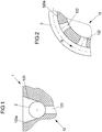
- im Querschnitt und ausschnittsweise ein Ausführungsbeispiel eines Mitnehmers mit Blick auf eine kanalförmige (Seil-) Führung und eine an einer Führungsfläche dieser Führung ausgebildete Aussparung in Form einer Durchgangsöffnung zum Abführen von Partikeln;
- Figur 2
- ausschnittsweise den Mitnehmer der
Figur 1 im Längsschnitt unter Veranschaulichung mehrerer aufeinanderfolgender Durchgangsöffnungen entlang einer Längserstreckungsrichtung der Führung und eines darin um 90° umgelenkten Seils; - Figuren 3A bis 3I
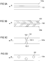
- ausschnittsweise und jeweils in Draufsicht weitere Varianten für die mit mindestens einer Aussparung versehene Führungsfläche des Mitnehmers;
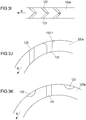
- Figur 3J bis 3K
- ausschnittsweise und jeweils im Längsschnitt weitere Varianten für an der Führungsfläche ausgebildete Aussparungen;
- Figur 4
- in Seitenansicht ein Fahrzeugfensterheber mit zwei jeweils an einer Führungsschiene verschieblich gelagerten Mitnehmern;
- Figur 5
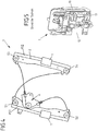
- in perspektivischer Ansicht ein aus dem Stand der Technik bekannter Mitnehmer;
- Figur 6
- ausschnittsweise und in entsprechend der
Figur 1 geschnittener Ansicht eine an einem Mitnehmer ausgebildete Führung gemäß dem Stand der Technik; - Figur 7
- in mit der
Figur 2 übereinstimmender Ansicht ausschnittsweise der Mitnehmer derFigur 6 . - Die
Figur 4 zeigt in Seitenansicht einen üblichen Aufbau eines Fahrzeugfensterhebers F für die Verstellung einer hier nicht dargestellten Fensterscheibe in einem Fahrzeug. Der Fahrzeugfensterheber F weist hier zwei im Wesentlichen parallel zueinander orientierte Führungsschienen FS1 und FS2 auf. An diesen Führungsschienen FS1 und FS2 ist jeweils ein Mitnehmer 1 verschieblich gelagert. Jeder Mitnehmer 1 ist mit einem Seil 2 des Fahrzeugfensterhebers F verbunden, das über mehrere Umlenkelemente in Form von Seilrollen S1 bis S4 umgelenkt ist. Die Seilrollen S1 bis S4 sind hierbei jeweils an einem oberen und unteren Ende der Führungsschienen FS1 und FS2 drehbar gelagert. - Das Seil 2 steht ferner mit einer Antriebseinheit A des Fahrzeugfensterhebers F in Verbindung. Diese Antriebseinheit A umfasst üblicherweise einen Antriebsmotor und eine hiervon angetriebene Seiltrommel, an der ein Abschnitt des Seiles 2 aufgewickelt und abgewickelt werden kann, um mittels des Seiles 2 eine Verstellkraft an die Mitnehmer 1 zum Anheben oder Absenken der Fensterscheibe zu übertragen. Je nach Drehrichtung des Antriebsmotors der Antriebseinheit A werden die beiden Mitnehmer 1 entlang der Führungsschienen FS1 und FS2 synchron in eine von zwei möglichen zueinander entgegengesetzten Verstellrichtungen verstellt, sodass hierüber die mit beiden Mitnehmern 1 verbundene Fensterscheibe angehoben oder abgesenkt werden kann.
- Anhand der
Figur 5 ist exemplarisch ein aus dem Stand der Technik bekannter Mitnehmer 1 in perspektivischer Ansicht näher veranschaulicht. Der Mitnehmer 1 umfasst unter anderem einen Scheibenbefestigungsabschnitt 10, über den der Mitnehmer 1 an einer Scheibenunterkante der Fensterscheibe fixiert werden kann. Ferner umfasst der Mitnehmer 1 einen Führungsabschnitt 11. Über diesen Führungsabschnitt 11 kann ein Abschnitt an der jeweiligen Führungsschiene FS1, FS2 umgriffen werden, sodass der Mitnehmer 1 an der jeweiligen Führungsschiene FS1 oder FS2 verschieblich gehalten ist. Weiterhin umfasst der Mitnehmer 1 einen Grundkörper 12. An diesem Grundkörper 12 können der Scheibenbefestigungsabschnitt 10 und der Führungsabschnitt 11 ausgeformt oder befestigt sein. Ferner ist an dem Grundkörper 12 eine Verbindungsstelle für die Anbindung des Seiles 2 an den Mitnehmer 1 ausgebildet. Eine entsprechende Verbindungsstelle wird beispielsweise durch mindestens eine Nippelkammer ausgebildet, an der ein Seilnippel des Seiles 2 eingehängt werden kann. - Aus dem Stand der Technik ist nun ferner bekannt, dass an einem Grundkörper 12 eines Mitnehmers 1 eine Führung für die Umlenkung eines flexiblen Zugmittels, wie zum Beispiel des Seiles 2, ausgebildet sein kann, um den maximal möglichen Hub der Fensterscheibe zu erhöhen. Typischerweise wird hierbei ein Seil 2 im Bereich von 90° an dem Mitnehmer 1 umgelenkt. Ein entsprechender aus dem Stand der Technik bekannter Mitnehmer 1 ist dabei ausschnittsweise im Quer- und Längsschnitt in den
Figuren 6 und 7 dargestellt. - Das Seil 2 ist hierbei in einer kanalförmigen Seilführung 120 des Grundkörpers 12 des Mitnehmers 1 geführt. Das Seil 2 liegt folglich in diesem Bereich an einer Mantel- oder Führungsfläche 120a der als Seilkanal ausgestalteten Seilführung 120 an. Im Betrieb des Fahrzeugfensterhebers F kommt es zu einer Relativbewegung zwischen dem Seil 2 und der Führungsfläche 120a, an der entlang das Seil 2 an dem Mitnehmer 1 umgelenkt ist. Durch die Reibpaarung zwischen Seil 2 und Führungsfläche 120a kann es somit zu störenden Reib- oder Schleifgeräuschen kommen.
- Zur Vermeidung derartiger störender Geräusche ist es bereits bekannt, die Führung 120 an dem Mitnehmer 1 zu schmieren, z.B. zu fetten. Ein entsprechender Schmierstoff gelangt dann beispielsweise in Zwischenräume 210, die zwischen Drahtlitzen 20 des Seiles 2 vorhanden sind. Im Betrieb des Fahrzeugfensterhebers F kann es jedoch dazu kommen, dass von außen oder durch Abrieb Partikel, insbesondere Staub- oder Schmutzpartikel, in die Führung 120 und insbesondere zwischen das Seil 2 und die Führungsfläche 120a gelangen. Diese Partikel bilden dann mit dem Schmierstoff eine Reibpaste, die im Betrieb ebenso zu störenden Reib- oder Schleifgeräuschen führt.
- Hier kann die vorgeschlagene Lösung Abhilfe schaffen, zu der mögliche Ausführungsvarianten in den
Figuren 1 bis 3K dargestellt sind. - Hierbei ist an der Führungsfläche 120a des Mitnehmers 1 mindestens eine Aussparung 122 ausgebildet, über die Partikel aus der für das Seil 2 vorgesehenen Führung 120 abgeführt werden können. Über die mindestens eine Aussparung 122 können somit eventuell in die Führung 120 gelangte Partikel (durch Bewegung des Seiles 2 in der Führung 120 selbsttätig) entfernt werden.
- In den
Figuren 1 und 2 ist beispielsweise in mit denFiguren 6 und 7 übereinstimmenden Ansichten ausschnittsweise ein Mitnehmer 1 dargestellt, bei dem entlang einer Längserstreckungsrichtung L der Führung 120, die der Erstreckungsrichtung des an dem Mitnehmer 1 umgelenkten Seil 2 entspricht, mehrere (mindestens zwei) aufeinanderfolgende und jeweils als Durchgangsöffnungen ausgestaltete Aussparungen 122 an der Führungsfläche 120a ausgebildet sind. Über diese Durchgangsöffnungen oder -löcher der Aussparungen 122 können Partikel aus der Seilführung 120 abgeführt werden. Die Aussparungen 122 erstrecken sich hierbei im Wesentlichen senkrecht zur Längserstreckungsrichtung L der Seilführung 120. Beispielsweise sind die einzelnen Aussparungen 122 durch Perforationen an dem Grundkörper 12 des Mitnehmers 1 ausgebildet. - Indem etwaige in der Führung 120 vorhandene Partikel über die Aussparungen 122 aus der Führung 120 heraus gelangen können, ist deren Ansammlung an der Führungsfläche 120a verhindert. Es kann folglich auch zu keiner Vermengung dieser Partikel mit etwaigen Flüssigkeiten, Ölen oder Fetten innerhalb der Führung 120 kommen. Eine für die Entstehung von Reib- oder Schleifgeräuschen nachteilige Reifpaste kann somit nicht entstehen.
- Anstelle von einzelnen lokalen Aussparungen 122 in Form von Durchgangsöffnungen oder Durchgangslöchern kann beispielsweise auch entsprechend der Draufsicht der
Figur 3A eine mittig am Boden der Seilführung 120 verlaufende, längserstreckte kanalartige oder schlitzartige Aussparung 122 vorgesehen sein, um Partikel aus der Seilführung 120 abzuführen. Diese längserstreckte kanalartige oder schlitzartige Aussparung 122 verläuft hier z.B. parallel zur Längserstreckungsrichtung R der Seilführung 120. - Auch können geometrisch unterschiedlich ausgestaltete Aussparungen 122 und 123 miteinander kombiniert sein. Bei der Ausführungsvariante der
Figur 3B ist beispielsweise die kanalartige Aussparung 122 derFigur 3A mit schräg zur Längserstreckungsrichtung R verlaufenden und zueinander spiegelsymmetrischen Aussparungen 123 kombiniert. Die beiderseits der mittig verlaufenden, kanalartigen Aussparung 122 angeordneten schräg verlaufenden Aussparungen 123 erstrecken sich somit seitlich des Seiles 2, wenn dieses an dem Mitnehmer 1 bestimmungsgemäß umgelenkt ist, und laufen aufeinander zu. - Eine Aussparung 122 an der Führungsfläche 120a entsprechend der Ausführungsvariante der
Figur 3C verläuft demgegenüber im Wesentlichen quer zur Längserstreckungsrichtung R. Die Aussparung 122 derFigur 3C weist hierbei einen mittigen Abschnitt 122.3 auf, an den sich beiderseits jeweils ein weiterer Abschnitt 122.1, 122.2 nach außen hin anschließt. Diese (Rand-) Abschnitte 122.1 und 122.2 weiten sich dabei nach außen hin auf und gestatten somit den Austritt größerer Partikel sowie größerer Mengen an Partikeln in einem randseitigen Bereich der Führung 120. - Bei der Ausführungsvariante der
Figur 3D sind mehrere entlang der Längserstreckungsrichtung R hintereinander angeordnete Aussparungen 122 mit jeweils kreisförmigem Querschnitt vorgesehen. Unmittelbar aufeinanderfolgende Aussparungen 122 sind hierbei zusätzlich quer zur Längserstreckungsrichtung R zueinander versetzt. - Bei der Ausführungsvariante der
Figur 3E sind zwei einander gegenüberliegende Reihen von jeweils schräg zur Längserstreckungsrichtung R verlaufenden Aussparungen 122 und 123 an der Führungsfläche 120a ausgebildet. Die Reihen der Aussparungen 122 und 123 sind seitlich innerhalb der Führung 120 vorgesehen und verlaufen hierbei jeweils schräg zur Längserstreckungsrichtung R nach innen respektive nach unten in der Seilführung 120. - Bei der Ausführungsvariante der
Figur 3F sind jeweils quer zur Längserstreckungsrichtung R verlaufende, schlitzartige Aussparungen 122 an der Führungsfläche 120a ausgebildet, die zueinander unterschiedliche Abstände a und b aufweisen. - Bei der Ausführungsvariante der
Figur 3G sind entlang der Längserstreckungsrichtung R mehrere Aussparungen 122 mit jeweils ellipsenförmigem Querschnitt hintereinander angeordnet. - Bei der Ausführungsvariante der
Figur 3H weisen einzelne hintereinander angeordnete Aussparungen 122 jeweils einen S-förmigen Verlauf auf. - Bei der Ausführungsvariante der
Figur 3I sind in Übereinstimmung mit der Ausführungsvariante derFigur 3E einander gegenüberliegende Reihen von Aussparungen 122 und 123 an der Führungsfläche 120a ausgebildet, wobei die jeweiligen Aussparungen 122 und 123 einer Reihe jeweils schräg zur Längserstreckungsrichtung R verlaufen. Im Unterschied zu der Ausführungsvariante derFigur 3E sind hierbei die Aussparungen 122 und 123 mittels eines 2-Komponenten-Spritzguss an dem (üblicherweise aus Kunststoff hergestellten) Grundkörper 12 ausgebildet. - Die
Figuren 3J und 3K veranschaulichen ferner die Möglichkeit, Aussparungen 122 und 123 unterschiedlicher geometrischer Ausprägung miteinander an der für die Umlenkung des Seils 2 vorgesehenen Führungsfläche 120a des Mitnehmers 1 miteinander zu kombinieren. Hierbei sieht beispielsweise dieFigur 3J eine Aussparung 122 mit einem sich trichterförmig aufweitenden Randabschnitt 122.1 vor. Zusätzlich ist eine Aussparung 122 entsprechend derFiguren 1, 2 oder3F vorgesehen. Bei der Ausführungsvariante derFigur 3K sind wiederum ellipsenförmige Aussparungen 122 sowie längserstreckte und quer zur Längserstreckungsrichtung R verlaufende Aussparungen 123 miteinander kombiniert. - Anstelle oder zusätzlich zu Aussparungen 122, 123, die als Durchgangsöffnungen oder Durchgangslöcher an der Seilführung 120 ausgebildet sind, können selbstverständlich auch Aussparungen als Vertiefungen an der Führungsfläche 120a ausgebildet sein. Derartige Vertiefungen können insbesondere eine Durchgangsöffnung beranden. Derart können sich beispielsweise Partikel zunächst in der Vertiefung sammeln und dann - durch nachrückende Partikeln - über die Durchgangsöffnung vollständig aus der Führung 120 heraus gefördert werden.
- Grundsätzlich sind die einzelnen Aussparungen 122 und 123 an denjenigen Bereichen der Führungsfläche 120a vorgesehen, an der im Betrieb des Fahrzeugfensterhebers F das Seil 2 anliegt. Das Seil 2 erstreckt sich somit über die jeweiligen Aussparungen 122 und 123 im Betrieb des Fahrzeugfensterhebers F hinweg und fördert damit durch seine Relativbewegung an dem Mitnehmer 1 Partikel aus der Seilführung 120 zu den Aussparungen 122, 123 und damit aus der Führung 120 heraus. Etwaige in der Seilführung 120 durch Abrieb oder Einwirkung von außen eingebrachte Partikel werden damit an definierten Aussparungen 122 und 123 aus der kanalartigen Seilführung 120 heraus geführt, sodass hierdurch keine störenden Reib- oder Schleifgeräusche verursacht werden.
-
- 1
- Mitnehmer
- 10
- Scheibenbefestigungsabschnitt
- 11
- Führungsabschnitt
- 12
- Grundkörper
- 120
- Seilführung (Führung)
- 120a
- Mantel- / Führungsfläche
- 122, 123
- Aussparung
- 122.1, 122.2
- Randabschnitt
- 122.3
- Mittiger Abschnitt
- 2
- Seil (Zugmittel)
- 20
- Drahtlitzen
- 21
- Zwischenraum
- A
- Antriebseinheit
- a, b
- Abstand
- F
- Fahrzeugfensterheber
- FS1, FS2
- Führungsschiene (Führung)
- R
- Längserstreckungsrichtung
- S1 - S4
- Seilrolle (Umlenkelement)
Claims (14)
- Mitnehmer (1) für einen Fahrzeugfensterheber (F), der mit einer mittels des Fahrzeugfensterhebers (F) zu verstellenden Fensterscheibe zu verbinden ist und der eine Führung (120) für die Umlenkung eines Zugmittels (2) des Fahrzeugfensterhebers (F) aufweist, wobei die Führung (120) eine Führungsfläche (120a) ausbildet, an der bei bestimmungsgemäßer Montage des Fahrzeugfensterhebers (F) das Zugmittel (2) anliegt,
dadurch gekennzeichnet, dass
an der Führungsfläche (120a) mindestens eine Aussparung (122, 123) zum Abführen von Partikeln aus der für das Zugmittel (2) vorgesehenen Führung (120) des Mitnehmers (1) ausgebildet ist. - Mitnehmer nach Anspruch 1, dadurch gekennzeichnet, dass die mindestens eine Aussparung (122, 123) eine Vertiefung in der Führungsfläche (120a) ausbildet.
- Mitnehmer nach Anspruch 1 oder 2, dadurch gekennzeichnet, dass die mindestens eine Aussparung (122, 123) eine Durchgangsöffnung ausbildet.
- Mitnehmer nach einem der Ansprüche 1 bis 3, dadurch gekennzeichnet, dass die mindestens eine Aussparung (122, 123) längserstreckt ausgebildet ist.
- Mitnehmer nach Anspruch 4, dadurch gekennzeichnet, dass eine Längsachse der mindestens einen Aussparung (122, 123) parallel, schräg oder quer zu einer Längserstreckungsrichtung (R) der Führung (120) verläuft.
- Mitnehmer nach einem der Ansprüche 1 bis 3, dadurch gekennzeichnet, dass die mindestens eine Aussparung (122, 123) einen kreisförmigen oder ellipsenförmigen Querschnitt aufweist.
- Mitnehmer nach einem der Ansprüche 1 bis 3, dadurch gekennzeichnet, dass die mindestens eine Aussparung (122) einen ersten Abschnitt (122.3) und mindestens einen zweiten Abschnitt (122.1, 122.2) aufweist, wobei sich der mindestens eine zweite Abschnitt (122.1, 122.2) an den ersten Abschnitt (122.3) in einer Richtung anschließt und sich entlang dieser Richtung aufweitet.
- Mitnehmer nach einem der Ansprüche 1 bis 4 oder dem Anspruch 7, dadurch gekennzeichnet, dass die mindestens eine Aussparung (122, 123) S-förmig an der Führungsfläche (120a) verläuft.
- Mitnehmer nach einem der vorhergehenden Ansprüche, dadurch gekennzeichnet, dass mehrere entlang einer Längserstreckungsrichtung (R) der Führung (120) aufeinanderfolgende Aussparungen (122, 123) an der Führungsfläche (120a) ausgebildet sind.
- Mitnehmer nach Anspruch 9, dadurch gekennzeichnet, dass mindestens zwei der mehreren entlang der Längserstreckungsrichtung (R) der Führung (120) aufeinanderfolgenden Aussparungen (122, 123) zueinander verschiedene Querschnittsformen aufweisen.
- Mitnehmer nach Anspruch 9 oder 10, dadurch gekennzeichnet, dass die mehreren entlang der Längserstreckungsrichtung (R) der Führung (120) aufeinanderfolgenden Aussparungen (122, 123) äquidistant zueinander beabstandet sind.
- Mitnehmer nach Anspruch 9 oder 10, dadurch gekennzeichnet, dass entlang der Längserstreckungsrichtung (R) der Führung (120) aufeinanderfolgende Aussparungen (122, 123) mit zueinander unterschiedlichen Abständen (a, b) vorgesehen sind.
- Mitnehmer nach einem der Ansprüche 9 bis 12, dadurch gekennzeichnet, dass mindestens zwei der mehreren entlang der Längserstreckungsrichtung (R) der Führung (120) aufeinanderfolgenden Aussparungen (122, 123) quer zur Längserstreckungsrichtung (R) zueinander versetzt sind.
- Fahrzeugfensterheber für die Verstellung einer Fensterscheibe, mit einem flexiblen Zugmittel (2) für die Übertragung einer Verstellkraft zur Verstellung der Fensterscheibe, mindestens einem mit der Fensterscheibe zu verbindenden Mitnehmer (1) nach einem der Ansprüche 1 bis 13 und mindestens einer Führungsschiene (FS1, FS2), an der der mindestens eine Mitnehmer (1) verschieblich geführt ist, wobei der Mitnehmer (1) eine Führung (120) für die Umlenkung des flexiblen Zugmittels (2) an dem Mitnehmer (2) aufweist und die Führung (120) eine Führungsfläche (120a) ausbildet, an der das flexible Zugmittel (2) anliegt,
dadurch gekennzeichnet, dass
an der Führungsfläche (120a) mindestens eine Aussparung (122, 123) zum Abführen von Partikeln aus der für das flexible Zugmittel (2) vorgesehenen Führung (120) des Mitnehmers (1) ausgebildet ist.
Applications Claiming Priority (1)
| Application Number | Priority Date | Filing Date | Title |
|---|---|---|---|
| DE102017220617.9A DE102017220617A1 (de) | 2017-11-17 | 2017-11-17 | Mitnehmer und Fahrzeugfensterheber |
Publications (2)
| Publication Number | Publication Date |
|---|---|
| EP3486419A1 EP3486419A1 (de) | 2019-05-22 |
| EP3486419B1 true EP3486419B1 (de) | 2020-06-17 |
Family
ID=64172379
Family Applications (1)
| Application Number | Title | Priority Date | Filing Date |
|---|---|---|---|
| EP18204363.8A Active EP3486419B1 (de) | 2017-11-17 | 2018-11-05 | Mitnehmer und fahrzeugfensterheber |
Country Status (4)
| Country | Link |
|---|---|
| US (1) | US11118391B2 (de) |
| EP (1) | EP3486419B1 (de) |
| CN (1) | CN109854118B (de) |
| DE (1) | DE102017220617A1 (de) |
Families Citing this family (3)
| Publication number | Priority date | Publication date | Assignee | Title |
|---|---|---|---|---|
| JP7187980B2 (ja) * | 2018-10-29 | 2022-12-13 | 株式会社アイシン | ウインドレギュレータ及びその組付方法 |
| DE102019207262A1 (de) * | 2019-05-17 | 2020-11-19 | Brose Fahrzeugteile Se & Co. Kommanditgesellschaft, Bamberg | Umlenkelement und Fensterheberbaugruppe |
| KR20250141366A (ko) * | 2024-03-20 | 2025-09-29 | 현대자동차주식회사 | 분리형 슬라이더 고정 레일을 갖춘 차량용 플러시 도어 및 플러시 도어 조립 방법 |
Family Cites Families (18)
| Publication number | Priority date | Publication date | Assignee | Title |
|---|---|---|---|---|
| NL7907433A (nl) * | 1979-10-08 | 1981-04-10 | Philips Nv | Kabel voorzien van optische vezels. |
| DE19619057A1 (de) * | 1996-05-03 | 1997-11-06 | Brose Fahrzeugteile | Seilfensterheber mit vergrößertem Hub |
| DE20202352U1 (de) * | 2002-02-15 | 2002-04-18 | Brose Fahrzeugteile GmbH & Co. Kommanditgesellschaft, 96450 Coburg | Bahngesteuerter Seilfensterheber für eine Fensterscheibe eines Kraftfahrzeuges |
| DE10220948A1 (de) * | 2002-04-30 | 2003-11-20 | Brose Fahrzeugteile | Kraftfahrzeugfensterheber |
| JP2008006914A (ja) | 2006-06-28 | 2008-01-17 | Hi-Lex Corporation | キャリアプレートおよび該キャリアプレートを備えたウインドレギュレータ |
| DE202006013425U1 (de) * | 2006-08-31 | 2008-01-03 | Brose Fahrzeugteile Gmbh & Co. Kommanditgesellschaft, Coburg | Mitnehmer in einem Seilfensterheber |
| EP2152996B1 (de) * | 2007-05-09 | 2014-09-24 | Magna Closures Inc. | Fensterstelleranordnung für ein fahrzeug |
| DE102009053812A1 (de) * | 2008-11-28 | 2011-02-03 | Küster Holding GmbH | Gehäuse zur Aufnahme einer Seiltrommel einer Verstelleinrichtung für ein Kraftfahrzeug |
| KR101081111B1 (ko) * | 2008-12-05 | 2011-11-07 | 현대자동차주식회사 | 변속케이블의 댐퍼장치 |
| US8556234B2 (en) * | 2009-11-13 | 2013-10-15 | Ride Inc. | Single cable descent control device |
| JP5044002B2 (ja) * | 2010-08-27 | 2012-10-10 | 株式会社ハイレックスコーポレーション | ウインドレギュレータ |
| CN203755879U (zh) | 2013-12-19 | 2014-08-06 | 安徽工程大学 | 一种玻璃升降器托架润滑脂保存机构 |
| CN203808709U (zh) | 2014-04-01 | 2014-09-03 | 上海通用汽车有限公司 | 一种用于玻璃升降器的钢丝绳固定组件 |
| CN204552416U (zh) | 2015-03-23 | 2015-08-12 | 长春海德世汽车拉索有限公司 | 一种结构优化的玻璃升降器托架 |
| CN204782483U (zh) | 2015-07-08 | 2015-11-18 | 宁波世通汽车零部件有限公司 | 绳轮式电动玻璃升降器 |
| JP2017190598A (ja) * | 2016-04-12 | 2017-10-19 | シロキ工業株式会社 | 車両用ウインドレギュレータ |
| JP6887884B2 (ja) * | 2017-06-02 | 2021-06-16 | 株式会社ミツバ | 車両用開閉装置 |
| JP6985892B2 (ja) * | 2017-11-06 | 2021-12-22 | シロキ工業株式会社 | ウインドレギュレータ |
-
2017
- 2017-11-17 DE DE102017220617.9A patent/DE102017220617A1/de not_active Withdrawn
-
2018
- 2018-11-05 EP EP18204363.8A patent/EP3486419B1/de active Active
- 2018-11-15 US US16/192,086 patent/US11118391B2/en active Active
- 2018-11-16 CN CN201811366114.2A patent/CN109854118B/zh active Active
Non-Patent Citations (1)
| Title |
|---|
| None * |
Also Published As
| Publication number | Publication date |
|---|---|
| CN109854118B (zh) | 2020-08-04 |
| DE102017220617A1 (de) | 2019-05-23 |
| EP3486419A1 (de) | 2019-05-22 |
| US11118391B2 (en) | 2021-09-14 |
| US20190162004A1 (en) | 2019-05-30 |
| CN109854118A (zh) | 2019-06-07 |
Similar Documents
| Publication | Publication Date | Title |
|---|---|---|
| EP3486419B1 (de) | Mitnehmer und fahrzeugfensterheber | |
| DE102012214270A1 (de) | Schubkette, Antriebsvorrichtung zur linearen Bewegung sowie Untersuchungsbett | |
| EP1316465A1 (de) | Arretiervorrichtung mit gerillten Sperrstiften | |
| EP3768925B1 (de) | Mitnehmer für einen fahrzeugfensterheber | |
| DE3600413C2 (de) | ||
| EP1367207A2 (de) | Antriebsvorrichtung, insbesondere für einen Fahrzeugschiebedachdeckel, sowie Fahrzeugschiebedach | |
| DE102020108811A1 (de) | Selbsthaltende riemenscheibe für lenkbaugruppe | |
| EP3300936B1 (de) | Lager für ein bauteil eines kraftfahrzeugs | |
| DE202017106108U1 (de) | Leitungsführungssystem und Führungsrinne, insbesondere für hohe Verfahrgeschwindigkeiten | |
| EP1369275A1 (de) | Rollo mit seitlicher Führung | |
| DE4419175C1 (de) | Antriebsvorrichtung für Sonnendächer von Kraftfahrzeugen | |
| EP3085867B1 (de) | Tor | |
| DE19981927C1 (de) | Seilzug-Fensterheber für Fahrzeuge | |
| DE102018010291B4 (de) | Mitnehmer für einen Fahrzeugfensterheber | |
| DE102017210293B4 (de) | Kettenführung | |
| DE102009003364A1 (de) | Wälzkörperkäfig für eine Möbelauszugsführung und Verfahren zur Montage eines Wälzkörperkäfigs | |
| EP0853201A1 (de) | Vorrichtung zum automatischen, stufenweisen Seillängenausgleich eines Bowdenzugsystems | |
| DE202005014233U1 (de) | Gliederschürzeneinrichtung | |
| DE102019207262A1 (de) | Umlenkelement und Fensterheberbaugruppe | |
| DE10242825B4 (de) | Arretiervorrichtung mit gerillten Sperrstiften | |
| EP3502015B1 (de) | Fördervorrichtung | |
| EP2881354B1 (de) | Aufzugsanlage mit einem Kompensationsmittelstrang | |
| EP3925916B1 (de) | Aufzugstür mit einer türblattführung | |
| EP3471982B1 (de) | Dreipunktlagerung einer schiebetür | |
| DE102017212877B4 (de) | Kettenantriebsvorrichtung und Kettenführung |
Legal Events
| Date | Code | Title | Description |
|---|---|---|---|
| PUAI | Public reference made under article 153(3) epc to a published international application that has entered the european phase |
Free format text: ORIGINAL CODE: 0009012 |
|
| STAA | Information on the status of an ep patent application or granted ep patent |
Free format text: STATUS: THE APPLICATION HAS BEEN PUBLISHED |
|
| AK | Designated contracting states |
Kind code of ref document: A1 Designated state(s): AL AT BE BG CH CY CZ DE DK EE ES FI FR GB GR HR HU IE IS IT LI LT LU LV MC MK MT NL NO PL PT RO RS SE SI SK SM TR |
|
| AX | Request for extension of the european patent |
Extension state: BA ME |
|
| STAA | Information on the status of an ep patent application or granted ep patent |
Free format text: STATUS: REQUEST FOR EXAMINATION WAS MADE |
|
| 17P | Request for examination filed |
Effective date: 20191122 |
|
| RBV | Designated contracting states (corrected) |
Designated state(s): AL AT BE BG CH CY CZ DE DK EE ES FI FR GB GR HR HU IE IS IT LI LT LU LV MC MK MT NL NO PL PT RO RS SE SI SK SM TR |
|
| RIC1 | Information provided on ipc code assigned before grant |
Ipc: E05F 7/04 20060101ALN20191209BHEP Ipc: E05F 11/48 20060101ALI20191209BHEP Ipc: E05F 11/38 20060101AFI20191209BHEP |
|
| GRAP | Despatch of communication of intention to grant a patent |
Free format text: ORIGINAL CODE: EPIDOSNIGR1 |
|
| STAA | Information on the status of an ep patent application or granted ep patent |
Free format text: STATUS: GRANT OF PATENT IS INTENDED |
|
| INTG | Intention to grant announced |
Effective date: 20200210 |
|
| RAP1 | Party data changed (applicant data changed or rights of an application transferred) |
Owner name: BROSE FAHRZEUGTEILE SE & CO. KOMMANDITGESELLSCHAFT, BAMBERG |
|
| GRAS | Grant fee paid |
Free format text: ORIGINAL CODE: EPIDOSNIGR3 |
|
| GRAA | (expected) grant |
Free format text: ORIGINAL CODE: 0009210 |
|
| STAA | Information on the status of an ep patent application or granted ep patent |
Free format text: STATUS: THE PATENT HAS BEEN GRANTED |
|
| AK | Designated contracting states |
Kind code of ref document: B1 Designated state(s): AL AT BE BG CH CY CZ DE DK EE ES FI FR GB GR HR HU IE IS IT LI LT LU LV MC MK MT NL NO PL PT RO RS SE SI SK SM TR |
|
| REG | Reference to a national code |
Ref country code: GB Ref legal event code: FG4D Free format text: NOT ENGLISH |
|
| REG | Reference to a national code |
Ref country code: CH Ref legal event code: EP |
|
| REG | Reference to a national code |
Ref country code: DE Ref legal event code: R096 Ref document number: 502018001695 Country of ref document: DE |
|
| REG | Reference to a national code |
Ref country code: IE Ref legal event code: FG4D Free format text: LANGUAGE OF EP DOCUMENT: GERMAN |
|
| REG | Reference to a national code |
Ref country code: AT Ref legal event code: REF Ref document number: 1281487 Country of ref document: AT Kind code of ref document: T Effective date: 20200715 |
|
| PG25 | Lapsed in a contracting state [announced via postgrant information from national office to epo] |
Ref country code: GR Free format text: LAPSE BECAUSE OF FAILURE TO SUBMIT A TRANSLATION OF THE DESCRIPTION OR TO PAY THE FEE WITHIN THE PRESCRIBED TIME-LIMIT Effective date: 20200918 Ref country code: LT Free format text: LAPSE BECAUSE OF FAILURE TO SUBMIT A TRANSLATION OF THE DESCRIPTION OR TO PAY THE FEE WITHIN THE PRESCRIBED TIME-LIMIT Effective date: 20200617 Ref country code: NO Free format text: LAPSE BECAUSE OF FAILURE TO SUBMIT A TRANSLATION OF THE DESCRIPTION OR TO PAY THE FEE WITHIN THE PRESCRIBED TIME-LIMIT Effective date: 20200917 Ref country code: SE Free format text: LAPSE BECAUSE OF FAILURE TO SUBMIT A TRANSLATION OF THE DESCRIPTION OR TO PAY THE FEE WITHIN THE PRESCRIBED TIME-LIMIT Effective date: 20200617 Ref country code: FI Free format text: LAPSE BECAUSE OF FAILURE TO SUBMIT A TRANSLATION OF THE DESCRIPTION OR TO PAY THE FEE WITHIN THE PRESCRIBED TIME-LIMIT Effective date: 20200617 |
|
| REG | Reference to a national code |
Ref country code: LT Ref legal event code: MG4D |
|
| REG | Reference to a national code |
Ref country code: NL Ref legal event code: MP Effective date: 20200617 |
|
| PG25 | Lapsed in a contracting state [announced via postgrant information from national office to epo] |
Ref country code: HR Free format text: LAPSE BECAUSE OF FAILURE TO SUBMIT A TRANSLATION OF THE DESCRIPTION OR TO PAY THE FEE WITHIN THE PRESCRIBED TIME-LIMIT Effective date: 20200617 Ref country code: RS Free format text: LAPSE BECAUSE OF FAILURE TO SUBMIT A TRANSLATION OF THE DESCRIPTION OR TO PAY THE FEE WITHIN THE PRESCRIBED TIME-LIMIT Effective date: 20200617 Ref country code: LV Free format text: LAPSE BECAUSE OF FAILURE TO SUBMIT A TRANSLATION OF THE DESCRIPTION OR TO PAY THE FEE WITHIN THE PRESCRIBED TIME-LIMIT Effective date: 20200617 Ref country code: BG Free format text: LAPSE BECAUSE OF FAILURE TO SUBMIT A TRANSLATION OF THE DESCRIPTION OR TO PAY THE FEE WITHIN THE PRESCRIBED TIME-LIMIT Effective date: 20200917 |
|
| PG25 | Lapsed in a contracting state [announced via postgrant information from national office to epo] |
Ref country code: AL Free format text: LAPSE BECAUSE OF FAILURE TO SUBMIT A TRANSLATION OF THE DESCRIPTION OR TO PAY THE FEE WITHIN THE PRESCRIBED TIME-LIMIT Effective date: 20200617 Ref country code: NL Free format text: LAPSE BECAUSE OF FAILURE TO SUBMIT A TRANSLATION OF THE DESCRIPTION OR TO PAY THE FEE WITHIN THE PRESCRIBED TIME-LIMIT Effective date: 20200617 |
|
| PG25 | Lapsed in a contracting state [announced via postgrant information from national office to epo] |
Ref country code: EE Free format text: LAPSE BECAUSE OF FAILURE TO SUBMIT A TRANSLATION OF THE DESCRIPTION OR TO PAY THE FEE WITHIN THE PRESCRIBED TIME-LIMIT Effective date: 20200617 Ref country code: PT Free format text: LAPSE BECAUSE OF FAILURE TO SUBMIT A TRANSLATION OF THE DESCRIPTION OR TO PAY THE FEE WITHIN THE PRESCRIBED TIME-LIMIT Effective date: 20201019 Ref country code: CZ Free format text: LAPSE BECAUSE OF FAILURE TO SUBMIT A TRANSLATION OF THE DESCRIPTION OR TO PAY THE FEE WITHIN THE PRESCRIBED TIME-LIMIT Effective date: 20200617 Ref country code: ES Free format text: LAPSE BECAUSE OF FAILURE TO SUBMIT A TRANSLATION OF THE DESCRIPTION OR TO PAY THE FEE WITHIN THE PRESCRIBED TIME-LIMIT Effective date: 20200617 Ref country code: IT Free format text: LAPSE BECAUSE OF FAILURE TO SUBMIT A TRANSLATION OF THE DESCRIPTION OR TO PAY THE FEE WITHIN THE PRESCRIBED TIME-LIMIT Effective date: 20200617 Ref country code: RO Free format text: LAPSE BECAUSE OF FAILURE TO SUBMIT A TRANSLATION OF THE DESCRIPTION OR TO PAY THE FEE WITHIN THE PRESCRIBED TIME-LIMIT Effective date: 20200617 Ref country code: SM Free format text: LAPSE BECAUSE OF FAILURE TO SUBMIT A TRANSLATION OF THE DESCRIPTION OR TO PAY THE FEE WITHIN THE PRESCRIBED TIME-LIMIT Effective date: 20200617 |
|
| PG25 | Lapsed in a contracting state [announced via postgrant information from national office to epo] |
Ref country code: PL Free format text: LAPSE BECAUSE OF FAILURE TO SUBMIT A TRANSLATION OF THE DESCRIPTION OR TO PAY THE FEE WITHIN THE PRESCRIBED TIME-LIMIT Effective date: 20200617 Ref country code: SK Free format text: LAPSE BECAUSE OF FAILURE TO SUBMIT A TRANSLATION OF THE DESCRIPTION OR TO PAY THE FEE WITHIN THE PRESCRIBED TIME-LIMIT Effective date: 20200617 Ref country code: IS Free format text: LAPSE BECAUSE OF FAILURE TO SUBMIT A TRANSLATION OF THE DESCRIPTION OR TO PAY THE FEE WITHIN THE PRESCRIBED TIME-LIMIT Effective date: 20201017 |
|
| REG | Reference to a national code |
Ref country code: DE Ref legal event code: R097 Ref document number: 502018001695 Country of ref document: DE |
|
| PLBE | No opposition filed within time limit |
Free format text: ORIGINAL CODE: 0009261 |
|
| STAA | Information on the status of an ep patent application or granted ep patent |
Free format text: STATUS: NO OPPOSITION FILED WITHIN TIME LIMIT |
|
| PG25 | Lapsed in a contracting state [announced via postgrant information from national office to epo] |
Ref country code: DK Free format text: LAPSE BECAUSE OF FAILURE TO SUBMIT A TRANSLATION OF THE DESCRIPTION OR TO PAY THE FEE WITHIN THE PRESCRIBED TIME-LIMIT Effective date: 20200617 |
|
| 26N | No opposition filed |
Effective date: 20210318 |
|
| PG25 | Lapsed in a contracting state [announced via postgrant information from national office to epo] |
Ref country code: SI Free format text: LAPSE BECAUSE OF FAILURE TO SUBMIT A TRANSLATION OF THE DESCRIPTION OR TO PAY THE FEE WITHIN THE PRESCRIBED TIME-LIMIT Effective date: 20200617 |
|
| PG25 | Lapsed in a contracting state [announced via postgrant information from national office to epo] |
Ref country code: MC Free format text: LAPSE BECAUSE OF FAILURE TO SUBMIT A TRANSLATION OF THE DESCRIPTION OR TO PAY THE FEE WITHIN THE PRESCRIBED TIME-LIMIT Effective date: 20200617 |
|
| PG25 | Lapsed in a contracting state [announced via postgrant information from national office to epo] |
Ref country code: LU Free format text: LAPSE BECAUSE OF NON-PAYMENT OF DUE FEES Effective date: 20201105 |
|
| REG | Reference to a national code |
Ref country code: BE Ref legal event code: MM Effective date: 20201130 |
|
| PG25 | Lapsed in a contracting state [announced via postgrant information from national office to epo] |
Ref country code: IE Free format text: LAPSE BECAUSE OF NON-PAYMENT OF DUE FEES Effective date: 20201105 |
|
| PG25 | Lapsed in a contracting state [announced via postgrant information from national office to epo] |
Ref country code: TR Free format text: LAPSE BECAUSE OF FAILURE TO SUBMIT A TRANSLATION OF THE DESCRIPTION OR TO PAY THE FEE WITHIN THE PRESCRIBED TIME-LIMIT Effective date: 20200617 Ref country code: MT Free format text: LAPSE BECAUSE OF FAILURE TO SUBMIT A TRANSLATION OF THE DESCRIPTION OR TO PAY THE FEE WITHIN THE PRESCRIBED TIME-LIMIT Effective date: 20200617 Ref country code: CY Free format text: LAPSE BECAUSE OF FAILURE TO SUBMIT A TRANSLATION OF THE DESCRIPTION OR TO PAY THE FEE WITHIN THE PRESCRIBED TIME-LIMIT Effective date: 20200617 |
|
| PG25 | Lapsed in a contracting state [announced via postgrant information from national office to epo] |
Ref country code: MK Free format text: LAPSE BECAUSE OF FAILURE TO SUBMIT A TRANSLATION OF THE DESCRIPTION OR TO PAY THE FEE WITHIN THE PRESCRIBED TIME-LIMIT Effective date: 20200617 |
|
| REG | Reference to a national code |
Ref country code: CH Ref legal event code: PL |
|
| PG25 | Lapsed in a contracting state [announced via postgrant information from national office to epo] |
Ref country code: BE Free format text: LAPSE BECAUSE OF NON-PAYMENT OF DUE FEES Effective date: 20201130 |
|
| PG25 | Lapsed in a contracting state [announced via postgrant information from national office to epo] |
Ref country code: LI Free format text: LAPSE BECAUSE OF NON-PAYMENT OF DUE FEES Effective date: 20211130 Ref country code: CH Free format text: LAPSE BECAUSE OF NON-PAYMENT OF DUE FEES Effective date: 20211130 |
|
| P01 | Opt-out of the competence of the unified patent court (upc) registered |
Effective date: 20230803 |
|
| PGFP | Annual fee paid to national office [announced via postgrant information from national office to epo] |
Ref country code: FR Payment date: 20230929 Year of fee payment: 6 |
|
| PGFP | Annual fee paid to national office [announced via postgrant information from national office to epo] |
Ref country code: GB Payment date: 20231006 Year of fee payment: 6 |
|
| REG | Reference to a national code |
Ref country code: AT Ref legal event code: MM01 Ref document number: 1281487 Country of ref document: AT Kind code of ref document: T Effective date: 20231105 |
|
| PG25 | Lapsed in a contracting state [announced via postgrant information from national office to epo] |
Ref country code: AT Free format text: LAPSE BECAUSE OF NON-PAYMENT OF DUE FEES Effective date: 20231105 |
|
| PG25 | Lapsed in a contracting state [announced via postgrant information from national office to epo] |
Ref country code: AT Free format text: LAPSE BECAUSE OF NON-PAYMENT OF DUE FEES Effective date: 20231105 |
|
| PGFP | Annual fee paid to national office [announced via postgrant information from national office to epo] |
Ref country code: DE Payment date: 20250109 Year of fee payment: 7 |
|
| GBPC | Gb: european patent ceased through non-payment of renewal fee |
Effective date: 20241105 |
|
| PG25 | Lapsed in a contracting state [announced via postgrant information from national office to epo] |
Ref country code: GB Free format text: LAPSE BECAUSE OF NON-PAYMENT OF DUE FEES Effective date: 20241105 |
|
| PG25 | Lapsed in a contracting state [announced via postgrant information from national office to epo] |
Ref country code: FR Free format text: LAPSE BECAUSE OF NON-PAYMENT OF DUE FEES Effective date: 20241130 |
|
| PGFP | Annual fee paid to national office [announced via postgrant information from national office to epo] |
Ref country code: AT Payment date: 20260410 Year of fee payment: 5 |