EP3482940B1 - Siebdruckmaschine mit isoliertem lötpastenspender - Google Patents
Siebdruckmaschine mit isoliertem lötpastenspender Download PDFInfo
- Publication number
- EP3482940B1 EP3482940B1 EP18020495.0A EP18020495A EP3482940B1 EP 3482940 B1 EP3482940 B1 EP 3482940B1 EP 18020495 A EP18020495 A EP 18020495A EP 3482940 B1 EP3482940 B1 EP 3482940B1
- Authority
- EP
- European Patent Office
- Prior art keywords
- printing machine
- shuttle
- cradle
- rail
- printing
- Prior art date
- Legal status (The legal status is an assumption and is not a legal conclusion. Google has not performed a legal analysis and makes no representation as to the accuracy of the status listed.)
- Active
Links
Images



Classifications
-
- B—PERFORMING OPERATIONS; TRANSPORTING
- B41—PRINTING; LINING MACHINES; TYPEWRITERS; STAMPS
- B41F—PRINTING MACHINES OR PRESSES
- B41F15/00—Screen printers
- B41F15/08—Machines
- B41F15/0804—Machines for printing sheets
- B41F15/0813—Machines for printing sheets with flat screens
-
- B—PERFORMING OPERATIONS; TRANSPORTING
- B41—PRINTING; LINING MACHINES; TYPEWRITERS; STAMPS
- B41F—PRINTING MACHINES OR PRESSES
- B41F15/00—Screen printers
- B41F15/14—Details
- B41F15/34—Screens, Frames; Holders therefor
-
- B—PERFORMING OPERATIONS; TRANSPORTING
- B41—PRINTING; LINING MACHINES; TYPEWRITERS; STAMPS
- B41F—PRINTING MACHINES OR PRESSES
- B41F15/00—Screen printers
- B41F15/14—Details
- B41F15/16—Printing tables
- B41F15/18—Supports for workpieces
-
- B—PERFORMING OPERATIONS; TRANSPORTING
- B41—PRINTING; LINING MACHINES; TYPEWRITERS; STAMPS
- B41F—PRINTING MACHINES OR PRESSES
- B41F15/00—Screen printers
- B41F15/14—Details
- B41F15/40—Inking units
-
- B—PERFORMING OPERATIONS; TRANSPORTING
- B41—PRINTING; LINING MACHINES; TYPEWRITERS; STAMPS
- B41F—PRINTING MACHINES OR PRESSES
- B41F15/00—Screen printers
- B41F15/14—Details
- B41F15/40—Inking units
- B41F15/42—Inking units comprising squeegees or doctors
-
- H—ELECTRICITY
- H05—ELECTRIC TECHNIQUES NOT OTHERWISE PROVIDED FOR
- H05K—PRINTED CIRCUITS; CASINGS OR CONSTRUCTIONAL DETAILS OF ELECTRIC APPARATUS; MANUFACTURE OF ASSEMBLAGES OF ELECTRICAL COMPONENTS
- H05K3/00—Apparatus or processes for manufacturing printed circuits
- H05K3/10—Apparatus or processes for manufacturing printed circuits in which conductive material is applied to the insulating support in such a manner as to form the desired conductive pattern
- H05K3/12—Apparatus or processes for manufacturing printed circuits in which conductive material is applied to the insulating support in such a manner as to form the desired conductive pattern using thick film techniques, e.g. printing techniques to apply the conductive material or similar techniques for applying conductive paste or ink patterns
- H05K3/1216—Apparatus or processes for manufacturing printed circuits in which conductive material is applied to the insulating support in such a manner as to form the desired conductive pattern using thick film techniques, e.g. printing techniques to apply the conductive material or similar techniques for applying conductive paste or ink patterns by screen printing or stencil printing
Definitions
- This invention relates to a printing machine for printing a print medium onto a workpiece.
- Industrial screen-printing machines typically apply print media, such as solder paste or conductive ink, onto a planar workpiece, such as a wafer or circuit board, by applying the print medium (e.g. solder paste) through a pattern of apertures in a screen (sometimes referred to as a foil or a stencil) using an angled blade or squeegee.
- the print medium is conventionally stored in a cartridge or pot, and is dispensed from the bottom of this by applying pressure to the top, using a pressurised air source.
- the cartridge is mounted on the print carriage, which also carries the squeegee. Since the print carriage travels along the length (i.e.
- the cartridge can dispense to either the front or rear rail of the printing machine.
- the cartridge is also mounted for movement along the X direction, being normal to the Y axis and in the horizontal plane, relative to the print carriage. In operation therefore, the print carriage is moved to one end of the printing machine, and the cartridge is caused to dispense print medium while travelling along the X direction, so that print medium is dispensed to form an approximately linear bead of medium onto the printing screen.
- the cartridge may be rotatable between a horizontal orientation when it is not dispensing, and a vertical orientation for dispensing.
- the quantity of print medium present in the cartridge can be detected by a sensor, and an operator alerted when the cartridge requires replacement.
- FIG. 1 schematically shows a known printing machine 1 in a perspective view.
- the printing machine 1 is substantially cuboid, having an external housing 2 which covers the printing machine 1 to prevent unauthorised access to the interior of the printing machine 1.
- the housing is mounted on a frame (not visible in FIG. 1 ), which also supports internal machinery and components.
- a hood 3 is provided to enable authorised access. This is connected to the remainder of the housing 2 via a hinge 4, so that the hood 3 can be lifted up and rested on top of the housing.
- an interlocking system (not shown) may be provided, which must be enabled prior to opening the hood 3.
- the present invention seeks to overcome this problem.
- this aim is achieved by providing isolation for the print medium cartridge, such as an isolated chamber which can be opened and accessed without interrupting the print process.
- the cartridge is also separated from the print carriage and carried on a static rail, fixed to the frame of the printing machine. While such an arrangement has the disadvantage that dispensing is only possible at on position, i.e. proximate the front or rear rail, it has been recognised that the advantages offered by this arrangement may outweigh the ability of conventional printing machines to dispense proximate both the front and rear rails of the printing machine.
- a printing machine for printing a print medium onto a workpiece comprising:
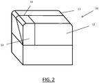
- FIG. 2 An embodiment of the present invention is schematically shown in FIG. 2 .
- This shows a perspective view of a closed printing machine 10, with an external housing 11 supported on a frame (15, see FIG. 3 ).
- a hood 12 provides access the interior of the printing machine 10.
- a separate door 13 is provided, which may be opened by lifting it about a hinge 14 connecting the door 13 to the housing 11.
- FIG. 3 shows both schematically and not to scale the printing machine 10 of FIG. 1 from the same viewpoint, though with the hood 12 and door 13 removed for clarity. In addition, and again for clarity, much of the printing machinery, in particular the print carriage, is omitted.
- the housing 11, and printing machinery and components are supported by frame 15.
- the internal volume of the printing machine 10 is partially separated into two distinct subvolumes by an internal partition 16: a main volume 17 and a container exchange volume 18, which is smaller than the main volume 17.
- the main volume 17 accommodates the printing machinery, including a print carriage with squeegee.
- Chases 22A, 22B are shown within the main volume 17, these chases 22A, 22B provide a receptacle for a printing screen S in use.
- chases are movable by actuators (not shown) to adjust the distance therebetween, so that a variety of differently-sized printing screens may be held by the chases 22A, 22B in use.
- a print carriage (not shown), including a squeegee, travels over the receptacle to act on a stencil S retained within, the direction of travel being parallel to the axes of the chases 22A, 22B, this direction conventionally being referred to as the "Y-direction".
- partition 16 includes an aperture 21, which permits communication between the two subvolumes. Passing through the aperture 21 proximate the upper edge thereof is a rail 19. Rail 19 extends at least partially across and over the receptacle, and in this embodiment across substantially the width of the printing machine 10, in a direction conventionally being referred to as the "X-direction". Rail 19 is statically fixed relative to the frame 15.
- the rail 19 is provided with a shuttle 23 mounted for travel along the rail 19.
- a cradle 24 is mounted on the shuttle 23 for travel therewith. Cradle 24 is adapted to retain a container for print medium (not shown). This container could for example comprise a cartridge or paste pot. It can be seen that shuttle 23 and cradle 24 are sized so as to fit through the aperture 21, so that they may travel into the main volume 17, and along the length of rail 19.
- FIG. 4 schematically shows, in a perspective view, a portion of the printing machine 10 of FIG. 2 with the shuttle 23 at the home position. More specifically, FIG. 4 shows the rail 19 with the shuttle 23 mounted thereon, with cradle 24 mounted on the shuttle 23.
- a paste cartridge 25 is located and securely retained within the cradle 24.
- the top of cradle 24 is open, so that a pneumatic line (not shown) can be fitted to a pneumatic connector 26 at the top of the paste cartridge 25. Supplying pressurised air through the pneumatic line and connector 26 will cause paste to be dispensed from the lower end of the paste cartridge 25.
- a printing medium sensor 27 is provided within the container exchange volume 18 so that it is proximate the lower end of a paste cartridge 25 when present in the cradle 24, and when the shuttle 23 is at the home position 20.
- the printing medium sensor 27 is operative to detect the presence of paste at the lower end of the paste cartridge 25 and output a simple YES / NO signal dependent on the determination of the presence of paste.
- the shuttle 23 comprises a wall section 28 at a lateral side of the cradle 24 furthest from the home position 20.
- the wall section 28 projects from the shuttle 23 towards the front of the printing machine 10, and is dimensioned so as to conform to the aperture 21, and furthermore located so as to align with the partition 16. In this way, when the shuttle 23 is at the home position 20, the cradle 24 is located in the container exchange volume 18 and the wall section 28 aligns with the partition 16 to isolate the container exchange volume 18 from the main volume 17.
- the rail 19 is provided with a programmable actuator 29 for moving the shuttle 23 along the rail 19.
- the rail 19 comprises a linear worm (not shown) selectively rotated by actuator 29, which drives the shuttle 23 along the rail as would be well understood by those skilled in the art.
- a pneumatic input 30 is provided to the rail 19, which connects to a pneumatic line (not shown) which runs along the rail 19 and connects to the shuttle 23. This pneumatic drive is used to effect vertical movement of the cradle 24 as will be described in more detail below, this vertical direction conventionally being referred to as the "Z-direction".
- the container exchange volume 18 is isolated from the main volume 17. It is possible for an operator to open the door 13 to access the container exchange volume 18, remove cartridge 25 from cradle 24 and exchange it with a fresh cartridge which can be placed in the cradle 24, all without having to open the hood 12. In this way the cartridge can be exchanged without interrupting the printing cycle, in complete safety for the operator.
- the need to exchange a cartridge is determined by the output from the printing medium sensor 27.
- FIG. 5 is a similar view to FIG. 4 , however in this case the shuttle 23 is shown moving to a dispensing position. Actuator 29 is caused to drive the linear worm to cause the shuttle 23 to move along the rail 19, through aperture 16, out of the container exchange volume 18 and into the main volume 17. It can be seen that the wall section 28 travels with the shuttle 23. It should be noted that with the cradle 24 in this configuration, the shuttle 23, cradle 24 and cartridge 25 can pass over the top of chase 22A (and indeed chase 22B if travel continues along the rail 19) to reach a position over the printing screen. However, to dispense printing medium properly, the cartridge 25 must be closer to the printing screen.
- the cradle 24 is adapted to be vertically movable with respect to the shuttle 23, so that it can be lowered into a dispensing position.
- the vertical position of the cradle 24 is controlled pneumatically, with the pneumatic input 30.
- FIG. 6 is a similar view to FIG. 5 , with the cradle 24 in its lowered dispensing position.
- the cradle 24 is mounted on shuttle 23 via a linear track 31, which guides the vertical motion.
- a dispensing action may commence, during which the shuttle 23, and hence also cradle 24 and cartridge 25, is moved along the rail 19 by driving actuator 29, while pneumatic pressure is applied to pneumatic connector 26, causing a bead or line of paste to be dispensed onto the printing screen S (see FIG. 3 ).
- the pneumatic pressure to pneumatic connector 26 is switched off, the cradle 24 is raised and the shuttle 23 is moved back to the home position 20 by actuator 29. Once the shuttle has reach the home position 20, printing of a workpiece through the printing screen S can be performed as is well-known in the art.
- Actuator 29 and the pneumatic drive are programmable so as to accommodate the chases 22A, 22B being set at different positions in the X-direction, and in particular to raise or lower the cradle 24 at preselected points of travel of the shuttle 23 along the rail 19.
- a control processor (not shown) is provided for controlling the actuator 29, the pneumatic supply for cradle 24 and the pneumatic supply for the cartridge 25 as required.
- FIG. 7 schematically shows a perspective view of a closed printing machine 40 in accordance with a second embodiment of the present invention.
- the external shape of the printing machine 40 is similar to that of the printing machine 10 shown in FIG. 2 , in particular housing 41 is very similar to housing 11.
- hood 42 and its connecting hinge 44 extend across the entirety of the front width of the printing machine 40.
- a lateral side of the hood 42 is provided with a hatch 43, which is mounted on hood 42 by a hinge 45, to open outwardly.
- FIG. 8 schematically shows, in perspective view, part of the internal configuration of the printing machine of FIG. 7 .
- FIG. 8 shows certain major components of the print medium dispensing system.
- a statically-fixed rail 49 is provided which extends across substantially the entire internal width of the printing machine 40.
- a shuttle 46 is mounted for travel along the rail 49, so as to traverse a printing screen (not shown) in use.
- the shuttle 46 carries a cradle 47 for retaining a print medium container (not shown), and a wall section 48 which projects perpendicularly to the rail 49.
- the cradle 47 is mounted on a projection 50 of the shuttle 46, which extends past the end of the rail 49 when the shuttle 46 is at an exchange position 51 proximate that end of the rail 49.
- the rail 49 and hatch 43 are aligned, so that when the shuttle 46 is moved along the rail 49 to the home position 51, the projection 50 abuts against and pushes open the hatch 43 from the inside of the printing machine 40, and passes to the outside of the printing machine 40.
- the cradle 47 therefore projects through the hatch 43, and outside the external housing 41.
- Wall section 48 then aligns with the external lateral surface of the external housing 41, providing at least partial isolation between the interior of the external housing 41 and the cradle 47.
- the wall section 48 is dimensioned to leave a gap between the wall section 48 and the hood 45, this gap being suitable for receiving the pneumatic line. As shown, the wall section 48 has a shorter dimension alone the Z-direction than the hatch 43, so that here a gap is formed above the wall section 48.
- the rails 19, 49 comprise linear worms driven by an actuator 29.
- Other drive systems are of course possible.
- the vertical movement of cradles 24, 47 described above uses a pneumatic system, other drive systems, for example electromechanical drive systems, may alternatively be used.
- the above-described embodiment shows the use of a paste cartridge, other containers, such as paste pots, and indeed other print media, such as conductive ink, may equally be dispensed.
- the hatch 43 could be opened in a variety of ways, for example by way of a dedicated actuator, or manually opened by an operator.
Landscapes
- Engineering & Computer Science (AREA)
- Mechanical Engineering (AREA)
- Manufacturing & Machinery (AREA)
- Microelectronics & Electronic Packaging (AREA)
- Electric Connection Of Electric Components To Printed Circuits (AREA)
- Screen Printers (AREA)
Claims (12)
- Siebdruckmaschine (10, 40) zum Drucken eines Druckmediums auf ein Werkstück, Folgendes umfassend:einen Rahmen (15),ein Außengehäuse (11, 41), das von dem Rahmen (15) getragen wird,einen Druckerwagen mit Rakel,eine Aufnahme zum Aufnehmen eines in Betrieb stehenden Drucksiebs (S),eine Schiene (19, 49), die sich mindestens teilweise quer über die und ober der Aufnahme erstreckt,eine Pendelvorrichtung (23, 46), die für das Fahren entlang der Schiene (19, 49) montiert ist, undeine Halterung (24, 47), die ausgelegt ist, um einen Behälter (25) für Druckmedium festzuhalten, wobei die Halterung (24, 47) auf der Pendelvorrichtung (23, 46) montiert ist,dadurch gekennzeichnet, dass die Schiene (19, 49) statisch relativ zum Rahmen befestigt ist und dass ein Teil der Schiene (19, 49) eine Austauschposition (51) für die Pendelvorrichtung (23, 46) umfasst, an welcher Position ein Behälter (25) für Druckmedium in der Halterung (24, 47) angeordnet bzw. von der Halterung entfernt werden kann, wobei der Behälter (25) von dem Druckerwagen getrennt ist.
- Druckmaschine (10) nach Anspruch 1, eine Innentrennwand (16) umfassend, die den Innenraum der Druckmaschine (10) teilweise in ein Hauptvolumen (17), das die Aufnahme umfasst, und ein Behälteraustauschvolumen (18), in dem die Austauschposition (51) angeordnet ist, trennt.
- Druckmaschine nach Anspruch 2, wobei die Pendelvorrichtung (23) einen Wandabschnitt (28) umfasst, wobei der Wandabschnitt (28) an einer lateralen Seite der Halterung (24) bereitgestellt ist, sodass die Halterung (24), wenn sich die Pendelvorrichtung (23) in der Austauschposition (51) befindet, in dem Behälteraustauschvolumen (18) angeordnet ist und der Wandabschnitt (28) mit der Trennwand (16) ausgerichtet ist, um das Behälteraustauschvolumen (18) von dem Hauptvolumen (17) zu isolieren.
- Druckmaschine (10) nach einem der Ansprüche 2 und 3, wobei das Gehäuse (11) eine Tür (13) umfasst, die nahe dem Behälteraustauschvolumen (18) angeordnet ist, um Zugang zu der Halterung (24) bereitzustellen, wenn sich die Pendelvorrichtung (23) in der Austauschposition (51) befindet.
- Druckmaschine (10, 40) nach Anspruch 1, wobei das Außengehäuse (11, 41) eine Klappe (43) umfasst.
- Druckmaschine (40) nach Anspruch 5, wobei, wenn sich die Pendelvorrichtung (46) in der Austauschposition (51) befindet, die Halterung (47) durch die Klappe (43) und außerhalb des Außengehäuses (41) vorsteht.
- Druckmaschine (40) nach Anspruch 6, wobei die Pendelvorrichtung (46) einen Wandabschnitt (48) umfasst, wobei der Wandabschnitt (48) an einer lateralen Seite der Halterung (47) bereitgestellt ist, sodass die Halterung (47), wenn sich die Pendelvorrichtung (46) in der Austauschposition (51) befindet, außerhalb des Außengehäuses (41) angeordnet ist und der Wandabschnitt (48) mit dem Außengehäuse (41) ausgerichtet ist, um die Halterung (47) von dem Innenraum des Gehäuses (41) zu isolieren.
- Druckmaschine (10, 40) nach einem der Ansprüche 1 bis 7, einen Aktuator (29) umfassend, um die Pendelvorrichtung (23, 46) entlang der Schiene (19, 49) zu bewegen.
- Druckmaschine (10, 40) nach einem der Ansprüche 1 bis 8, wobei die Halterung (24, 47) in vertikaler Richtung relativ zu der Pendelvorrichtung (23, 46) bewegbar ist.
- Druckmaschine (10, 40) nach Anspruch 9, einen Antrieb umfassend, um eine vertikale Bewegung der Halterung (24, 47) zu bewirken.
- Druckmaschine (10, 40) nach Anspruch 10, wobei der Antrieb einen pneumatischen Antrieb umfasst.
- Druckmaschine (10, 40) nach einem der Ansprüche 10 und 11, wobei der Antrieb programmiert werden kann, um die Halterung (24, 47) an vorgewählten Fahrpunkten der Pendelvorrichtung (23, 46) entlang der Schiene (19, 49) anzuheben oder abzusenken.
Applications Claiming Priority (1)
| Application Number | Priority Date | Filing Date | Title |
|---|---|---|---|
| GBGB1718674.3A GB201718674D0 (en) | 2017-11-12 | 2017-11-12 | Isolated paste dispenser |
Publications (2)
| Publication Number | Publication Date |
|---|---|
| EP3482940A1 EP3482940A1 (de) | 2019-05-15 |
| EP3482940B1 true EP3482940B1 (de) | 2020-05-13 |
Family
ID=60788304
Family Applications (1)
| Application Number | Title | Priority Date | Filing Date |
|---|---|---|---|
| EP18020495.0A Active EP3482940B1 (de) | 2017-11-12 | 2018-10-11 | Siebdruckmaschine mit isoliertem lötpastenspender |
Country Status (7)
| Country | Link |
|---|---|
| US (1) | US10882305B2 (de) |
| EP (1) | EP3482940B1 (de) |
| JP (1) | JP6840119B2 (de) |
| KR (1) | KR102239945B1 (de) |
| CN (1) | CN109878201B (de) |
| GB (1) | GB201718674D0 (de) |
| TW (1) | TWI742314B (de) |
Families Citing this family (2)
| Publication number | Priority date | Publication date | Assignee | Title |
|---|---|---|---|---|
| CN113710488B (zh) * | 2019-04-26 | 2023-07-14 | 株式会社富士 | 供给单元、印刷装置以及印刷装置的控制方法 |
| GB2597702B (en) * | 2020-07-30 | 2024-06-05 | Asmpt Smt Singapore Pte Ltd | Isolated print medium dispenser |
Family Cites Families (18)
| Publication number | Priority date | Publication date | Assignee | Title |
|---|---|---|---|---|
| JP2504643B2 (ja) * | 1991-08-23 | 1996-06-05 | 株式会社日立製作所 | 導電性ペ―スト充填装置 |
| JP3314425B2 (ja) * | 1992-12-02 | 2002-08-12 | 松下電器産業株式会社 | スクリーン印刷機及びその印刷方法 |
| US6101937A (en) * | 1997-02-12 | 2000-08-15 | Minami Co., Ltd. | Screen printing machine having paste dispensers and a squeegee unit |
| US6328415B1 (en) * | 1999-04-30 | 2001-12-11 | Hewlett-Packard Company | Displaceable print cartridge chute |
| JP3838240B2 (ja) | 2002-04-01 | 2006-10-25 | セイコーエプソン株式会社 | 液体噴射装置、液体噴射装置の制御方法及び制御プログラム |
| JP4675658B2 (ja) | 2005-03-28 | 2011-04-27 | パナソニック株式会社 | スクリーン印刷装置 |
| JP5252897B2 (ja) | 2007-11-30 | 2013-07-31 | ヤマハ発動機株式会社 | スクリーン印刷機 |
| JP4643719B2 (ja) * | 2009-02-09 | 2011-03-02 | ヤマハ発動機株式会社 | はんだ供給装置、印刷装置および印刷方法 |
| JP5062198B2 (ja) | 2009-02-24 | 2012-10-31 | パナソニック株式会社 | スクリーン印刷機及びスクリーン印刷方法 |
| FR2943634B1 (fr) | 2009-03-24 | 2011-04-22 | Cer | Machine et procede de marquage ou d'etiquetage |
| JP5537851B2 (ja) * | 2009-07-10 | 2014-07-02 | 富士機械製造株式会社 | スクリーン印刷機 |
| US8739699B2 (en) * | 2010-12-08 | 2014-06-03 | Illinois Tool Works Inc. | Combination stencil printer and dispenser and related methods |
| JP2014151507A (ja) | 2013-02-07 | 2014-08-25 | Panasonic Corp | ペースト供給装置、スクリーン印刷機、ペースト供給方法及びスクリーン印刷方法 |
| JP5895133B2 (ja) * | 2013-06-12 | 2016-03-30 | パナソニックIpマネジメント株式会社 | ペースト供給装置、スクリーン印刷機、ペースト供給方法及びスクリーン印刷方法 |
| JP2016179579A (ja) | 2015-03-24 | 2016-10-13 | パナソニックIpマネジメント株式会社 | スクリーン印刷装置、ペーストポット及びスクリーン印刷方法 |
| WO2017048905A1 (en) | 2015-09-15 | 2017-03-23 | Milara Incorporated | System and method for depositing a material on a workpiece |
| JP6971033B2 (ja) | 2017-01-24 | 2021-11-24 | 株式会社Fuji | スクリーン印刷機 |
| KR102799657B1 (ko) | 2017-02-08 | 2025-04-23 | 삼성전자주식회사 | 인쇄회로기판용 스크린 프린터 |
-
2017
- 2017-11-12 GB GBGB1718674.3A patent/GB201718674D0/en not_active Ceased
-
2018
- 2018-10-11 EP EP18020495.0A patent/EP3482940B1/de active Active
- 2018-10-19 TW TW107136845A patent/TWI742314B/zh active
- 2018-11-02 CN CN201811303415.0A patent/CN109878201B/zh active Active
- 2018-11-05 US US16/180,656 patent/US10882305B2/en active Active
- 2018-11-09 KR KR1020180137033A patent/KR102239945B1/ko active Active
- 2018-11-09 JP JP2018211355A patent/JP6840119B2/ja active Active
Non-Patent Citations (1)
| Title |
|---|
| None * |
Also Published As
| Publication number | Publication date |
|---|---|
| US10882305B2 (en) | 2021-01-05 |
| KR20190054946A (ko) | 2019-05-22 |
| TW201918382A (zh) | 2019-05-16 |
| TWI742314B (zh) | 2021-10-11 |
| EP3482940A1 (de) | 2019-05-15 |
| US20190143668A1 (en) | 2019-05-16 |
| KR102239945B1 (ko) | 2021-04-14 |
| CN109878201B (zh) | 2021-04-06 |
| CN109878201A (zh) | 2019-06-14 |
| GB201718674D0 (en) | 2017-12-27 |
| JP2019089327A (ja) | 2019-06-13 |
| JP6840119B2 (ja) | 2021-03-10 |
Similar Documents
| Publication | Publication Date | Title |
|---|---|---|
| US10882305B2 (en) | Isolated paste dispenser | |
| US8186825B2 (en) | Printing apparatus | |
| CN115157862B (zh) | 液体喷射装置、以及液体喷射装置的检测方法 | |
| EP3192658A2 (de) | Flüssigabfallbehälter und befestigung | |
| CN113453904B (zh) | 用于印刷机器中的印刷单元的辊的装运托架 | |
| JP2018118407A (ja) | スクリーン印刷機 | |
| CN104228322A (zh) | 膏剂供应设备、丝网印刷机、膏剂供应方法和丝网印刷方法 | |
| US10495988B2 (en) | Printing device and printing method | |
| JP2015522447A (ja) | 枚葉紙印刷機における付加的印刷装置 | |
| JP2026009226A (ja) | 交換フレーム | |
| US11490525B2 (en) | Supply unit, printing device, and method for controlling printing device | |
| JP2023533102A5 (de) | ||
| US11833843B2 (en) | Isolated print medium dispenser | |
| US9994033B2 (en) | Liquid supply device and liquid ejecting apparatus | |
| JP2008254294A (ja) | 樹脂封止装置及び吸引孔詰まり検出方法 | |
| JP2015101073A (ja) | プリンター及びプリンターの制御方法 | |
| US12377583B2 (en) | Automatic gel ribbon thickness adjustment device | |
| JP2020082610A (ja) | インクジェットプリンタ | |
| KR20130104711A (ko) | 그라비어 인쇄기의 독터링장치 | |
| WO2022113899A1 (ja) | 印刷装置 | |
| CN109249699B (zh) | 液体喷吐装置及干涉物的检测方法 | |
| JP2024084186A (ja) | 保護カバーおよび作業機 |
Legal Events
| Date | Code | Title | Description |
|---|---|---|---|
| PUAI | Public reference made under article 153(3) epc to a published international application that has entered the european phase |
Free format text: ORIGINAL CODE: 0009012 |
|
| STAA | Information on the status of an ep patent application or granted ep patent |
Free format text: STATUS: THE APPLICATION HAS BEEN PUBLISHED |
|
| AK | Designated contracting states |
Kind code of ref document: A1 Designated state(s): AL AT BE BG CH CY CZ DE DK EE ES FI FR GB GR HR HU IE IS IT LI LT LU LV MC MK MT NL NO PL PT RO RS SE SI SK SM TR |
|
| AX | Request for extension of the european patent |
Extension state: BA ME |
|
| STAA | Information on the status of an ep patent application or granted ep patent |
Free format text: STATUS: REQUEST FOR EXAMINATION WAS MADE |
|
| 17P | Request for examination filed |
Effective date: 20191112 |
|
| RBV | Designated contracting states (corrected) |
Designated state(s): AL AT BE BG CH CY CZ DE DK EE ES FI FR GB GR HR HU IE IS IT LI LT LU LV MC MK MT NL NO PL PT RO RS SE SI SK SM TR |
|
| RIC1 | Information provided on ipc code assigned before grant |
Ipc: B41F 15/40 20060101ALI20191220BHEP Ipc: B41F 15/42 20060101ALI20191220BHEP Ipc: B41F 15/08 20060101AFI20191220BHEP Ipc: H05K 3/12 20060101ALI20191220BHEP |
|
| GRAP | Despatch of communication of intention to grant a patent |
Free format text: ORIGINAL CODE: EPIDOSNIGR1 |
|
| STAA | Information on the status of an ep patent application or granted ep patent |
Free format text: STATUS: GRANT OF PATENT IS INTENDED |
|
| INTG | Intention to grant announced |
Effective date: 20200206 |
|
| GRAS | Grant fee paid |
Free format text: ORIGINAL CODE: EPIDOSNIGR3 |
|
| GRAA | (expected) grant |
Free format text: ORIGINAL CODE: 0009210 |
|
| STAA | Information on the status of an ep patent application or granted ep patent |
Free format text: STATUS: THE PATENT HAS BEEN GRANTED |
|
| AK | Designated contracting states |
Kind code of ref document: B1 Designated state(s): AL AT BE BG CH CY CZ DE DK EE ES FI FR GB GR HR HU IE IS IT LI LT LU LV MC MK MT NL NO PL PT RO RS SE SI SK SM TR |
|
| REG | Reference to a national code |
Ref country code: GB Ref legal event code: FG4D |
|
| REG | Reference to a national code |
Ref country code: CH Ref legal event code: EP |
|
| REG | Reference to a national code |
Ref country code: DE Ref legal event code: R096 Ref document number: 602018004239 Country of ref document: DE |
|
| REG | Reference to a national code |
Ref country code: AT Ref legal event code: REF Ref document number: 1269727 Country of ref document: AT Kind code of ref document: T Effective date: 20200615 |
|
| REG | Reference to a national code |
Ref country code: LT Ref legal event code: MG4D |
|
| REG | Reference to a national code |
Ref country code: NL Ref legal event code: MP Effective date: 20200513 |
|
| PG25 | Lapsed in a contracting state [announced via postgrant information from national office to epo] |
Ref country code: IS Free format text: LAPSE BECAUSE OF FAILURE TO SUBMIT A TRANSLATION OF THE DESCRIPTION OR TO PAY THE FEE WITHIN THE PRESCRIBED TIME-LIMIT Effective date: 20200913 Ref country code: PT Free format text: LAPSE BECAUSE OF FAILURE TO SUBMIT A TRANSLATION OF THE DESCRIPTION OR TO PAY THE FEE WITHIN THE PRESCRIBED TIME-LIMIT Effective date: 20200914 Ref country code: LT Free format text: LAPSE BECAUSE OF FAILURE TO SUBMIT A TRANSLATION OF THE DESCRIPTION OR TO PAY THE FEE WITHIN THE PRESCRIBED TIME-LIMIT Effective date: 20200513 Ref country code: NO Free format text: LAPSE BECAUSE OF FAILURE TO SUBMIT A TRANSLATION OF THE DESCRIPTION OR TO PAY THE FEE WITHIN THE PRESCRIBED TIME-LIMIT Effective date: 20200813 Ref country code: FI Free format text: LAPSE BECAUSE OF FAILURE TO SUBMIT A TRANSLATION OF THE DESCRIPTION OR TO PAY THE FEE WITHIN THE PRESCRIBED TIME-LIMIT Effective date: 20200513 Ref country code: GR Free format text: LAPSE BECAUSE OF FAILURE TO SUBMIT A TRANSLATION OF THE DESCRIPTION OR TO PAY THE FEE WITHIN THE PRESCRIBED TIME-LIMIT Effective date: 20200814 Ref country code: SE Free format text: LAPSE BECAUSE OF FAILURE TO SUBMIT A TRANSLATION OF THE DESCRIPTION OR TO PAY THE FEE WITHIN THE PRESCRIBED TIME-LIMIT Effective date: 20200513 |
|
| PG25 | Lapsed in a contracting state [announced via postgrant information from national office to epo] |
Ref country code: BG Free format text: LAPSE BECAUSE OF FAILURE TO SUBMIT A TRANSLATION OF THE DESCRIPTION OR TO PAY THE FEE WITHIN THE PRESCRIBED TIME-LIMIT Effective date: 20200813 Ref country code: LV Free format text: LAPSE BECAUSE OF FAILURE TO SUBMIT A TRANSLATION OF THE DESCRIPTION OR TO PAY THE FEE WITHIN THE PRESCRIBED TIME-LIMIT Effective date: 20200513 Ref country code: RS Free format text: LAPSE BECAUSE OF FAILURE TO SUBMIT A TRANSLATION OF THE DESCRIPTION OR TO PAY THE FEE WITHIN THE PRESCRIBED TIME-LIMIT Effective date: 20200513 Ref country code: HR Free format text: LAPSE BECAUSE OF FAILURE TO SUBMIT A TRANSLATION OF THE DESCRIPTION OR TO PAY THE FEE WITHIN THE PRESCRIBED TIME-LIMIT Effective date: 20200513 |
|
| REG | Reference to a national code |
Ref country code: AT Ref legal event code: MK05 Ref document number: 1269727 Country of ref document: AT Kind code of ref document: T Effective date: 20200513 |
|
| PG25 | Lapsed in a contracting state [announced via postgrant information from national office to epo] |
Ref country code: AL Free format text: LAPSE BECAUSE OF FAILURE TO SUBMIT A TRANSLATION OF THE DESCRIPTION OR TO PAY THE FEE WITHIN THE PRESCRIBED TIME-LIMIT Effective date: 20200513 Ref country code: NL Free format text: LAPSE BECAUSE OF FAILURE TO SUBMIT A TRANSLATION OF THE DESCRIPTION OR TO PAY THE FEE WITHIN THE PRESCRIBED TIME-LIMIT Effective date: 20200513 |
|
| PG25 | Lapsed in a contracting state [announced via postgrant information from national office to epo] |
Ref country code: CZ Free format text: LAPSE BECAUSE OF FAILURE TO SUBMIT A TRANSLATION OF THE DESCRIPTION OR TO PAY THE FEE WITHIN THE PRESCRIBED TIME-LIMIT Effective date: 20200513 Ref country code: RO Free format text: LAPSE BECAUSE OF FAILURE TO SUBMIT A TRANSLATION OF THE DESCRIPTION OR TO PAY THE FEE WITHIN THE PRESCRIBED TIME-LIMIT Effective date: 20200513 Ref country code: DK Free format text: LAPSE BECAUSE OF FAILURE TO SUBMIT A TRANSLATION OF THE DESCRIPTION OR TO PAY THE FEE WITHIN THE PRESCRIBED TIME-LIMIT Effective date: 20200513 Ref country code: EE Free format text: LAPSE BECAUSE OF FAILURE TO SUBMIT A TRANSLATION OF THE DESCRIPTION OR TO PAY THE FEE WITHIN THE PRESCRIBED TIME-LIMIT Effective date: 20200513 Ref country code: SM Free format text: LAPSE BECAUSE OF FAILURE TO SUBMIT A TRANSLATION OF THE DESCRIPTION OR TO PAY THE FEE WITHIN THE PRESCRIBED TIME-LIMIT Effective date: 20200513 Ref country code: AT Free format text: LAPSE BECAUSE OF FAILURE TO SUBMIT A TRANSLATION OF THE DESCRIPTION OR TO PAY THE FEE WITHIN THE PRESCRIBED TIME-LIMIT Effective date: 20200513 Ref country code: ES Free format text: LAPSE BECAUSE OF FAILURE TO SUBMIT A TRANSLATION OF THE DESCRIPTION OR TO PAY THE FEE WITHIN THE PRESCRIBED TIME-LIMIT Effective date: 20200513 |
|
| REG | Reference to a national code |
Ref country code: DE Ref legal event code: R097 Ref document number: 602018004239 Country of ref document: DE |
|
| PG25 | Lapsed in a contracting state [announced via postgrant information from national office to epo] |
Ref country code: SK Free format text: LAPSE BECAUSE OF FAILURE TO SUBMIT A TRANSLATION OF THE DESCRIPTION OR TO PAY THE FEE WITHIN THE PRESCRIBED TIME-LIMIT Effective date: 20200513 Ref country code: PL Free format text: LAPSE BECAUSE OF FAILURE TO SUBMIT A TRANSLATION OF THE DESCRIPTION OR TO PAY THE FEE WITHIN THE PRESCRIBED TIME-LIMIT Effective date: 20200513 |
|
| PLBE | No opposition filed within time limit |
Free format text: ORIGINAL CODE: 0009261 |
|
| STAA | Information on the status of an ep patent application or granted ep patent |
Free format text: STATUS: NO OPPOSITION FILED WITHIN TIME LIMIT |
|
| 26N | No opposition filed |
Effective date: 20210216 |
|
| PG25 | Lapsed in a contracting state [announced via postgrant information from national office to epo] |
Ref country code: SI Free format text: LAPSE BECAUSE OF FAILURE TO SUBMIT A TRANSLATION OF THE DESCRIPTION OR TO PAY THE FEE WITHIN THE PRESCRIBED TIME-LIMIT Effective date: 20200513 |
|
| PG25 | Lapsed in a contracting state [announced via postgrant information from national office to epo] |
Ref country code: LU Free format text: LAPSE BECAUSE OF NON-PAYMENT OF DUE FEES Effective date: 20201011 Ref country code: MC Free format text: LAPSE BECAUSE OF FAILURE TO SUBMIT A TRANSLATION OF THE DESCRIPTION OR TO PAY THE FEE WITHIN THE PRESCRIBED TIME-LIMIT Effective date: 20200513 |
|
| REG | Reference to a national code |
Ref country code: BE Ref legal event code: MM Effective date: 20201031 |
|
| PG25 | Lapsed in a contracting state [announced via postgrant information from national office to epo] |
Ref country code: BE Free format text: LAPSE BECAUSE OF NON-PAYMENT OF DUE FEES Effective date: 20201031 |
|
| PG25 | Lapsed in a contracting state [announced via postgrant information from national office to epo] |
Ref country code: IE Free format text: LAPSE BECAUSE OF NON-PAYMENT OF DUE FEES Effective date: 20201011 |
|
| REG | Reference to a national code |
Ref country code: CH Ref legal event code: PL |
|
| PG25 | Lapsed in a contracting state [announced via postgrant information from national office to epo] |
Ref country code: TR Free format text: LAPSE BECAUSE OF FAILURE TO SUBMIT A TRANSLATION OF THE DESCRIPTION OR TO PAY THE FEE WITHIN THE PRESCRIBED TIME-LIMIT Effective date: 20200513 Ref country code: MT Free format text: LAPSE BECAUSE OF FAILURE TO SUBMIT A TRANSLATION OF THE DESCRIPTION OR TO PAY THE FEE WITHIN THE PRESCRIBED TIME-LIMIT Effective date: 20200513 Ref country code: CY Free format text: LAPSE BECAUSE OF FAILURE TO SUBMIT A TRANSLATION OF THE DESCRIPTION OR TO PAY THE FEE WITHIN THE PRESCRIBED TIME-LIMIT Effective date: 20200513 |
|
| PG25 | Lapsed in a contracting state [announced via postgrant information from national office to epo] |
Ref country code: MK Free format text: LAPSE BECAUSE OF FAILURE TO SUBMIT A TRANSLATION OF THE DESCRIPTION OR TO PAY THE FEE WITHIN THE PRESCRIBED TIME-LIMIT Effective date: 20200513 |
|
| PG25 | Lapsed in a contracting state [announced via postgrant information from national office to epo] |
Ref country code: LI Free format text: LAPSE BECAUSE OF NON-PAYMENT OF DUE FEES Effective date: 20211031 Ref country code: CH Free format text: LAPSE BECAUSE OF NON-PAYMENT OF DUE FEES Effective date: 20211031 |
|
| REG | Reference to a national code |
Ref country code: DE Ref legal event code: R081 Ref document number: 602018004239 Country of ref document: DE Owner name: ASMPT SMT SINGAPORE PTE. LTD., SG Free format text: FORMER OWNER: ASM ASSEMBLY SYSTEMS SINGAPORE PTE LTD., SINGAPUR, SG |
|
| P01 | Opt-out of the competence of the unified patent court (upc) registered |
Effective date: 20230530 |
|
| PGFP | Annual fee paid to national office [announced via postgrant information from national office to epo] |
Ref country code: DE Payment date: 20251021 Year of fee payment: 8 |
|
| PGFP | Annual fee paid to national office [announced via postgrant information from national office to epo] |
Ref country code: GB Payment date: 20251022 Year of fee payment: 8 |
|
| PGFP | Annual fee paid to national office [announced via postgrant information from national office to epo] |
Ref country code: IT Payment date: 20251024 Year of fee payment: 8 |
|
| PGFP | Annual fee paid to national office [announced via postgrant information from national office to epo] |
Ref country code: FR Payment date: 20251030 Year of fee payment: 8 |