EP3479007B1 - Tankventil - Google Patents
Tankventil Download PDFInfo
- Publication number
- EP3479007B1 EP3479007B1 EP17734241.7A EP17734241A EP3479007B1 EP 3479007 B1 EP3479007 B1 EP 3479007B1 EP 17734241 A EP17734241 A EP 17734241A EP 3479007 B1 EP3479007 B1 EP 3479007B1
- Authority
- EP
- European Patent Office
- Prior art keywords
- valve
- base body
- body section
- tank
- compressed gas
- Prior art date
- Legal status (The legal status is an assumption and is not a legal conclusion. Google has not performed a legal analysis and makes no representation as to the accuracy of the status listed.)
- Active
Links
Images


Classifications
-
- F—MECHANICAL ENGINEERING; LIGHTING; HEATING; WEAPONS; BLASTING
- F16—ENGINEERING ELEMENTS AND UNITS; GENERAL MEASURES FOR PRODUCING AND MAINTAINING EFFECTIVE FUNCTIONING OF MACHINES OR INSTALLATIONS; THERMAL INSULATION IN GENERAL
- F16K—VALVES; TAPS; COCKS; ACTUATING-FLOATS; DEVICES FOR VENTING OR AERATING
- F16K1/00—Lift valves or globe valves, i.e. cut-off apparatus with closure members having at least a component of their opening and closing motion perpendicular to the closing faces
- F16K1/30—Lift valves or globe valves, i.e. cut-off apparatus with closure members having at least a component of their opening and closing motion perpendicular to the closing faces specially adapted for pressure containers
- F16K1/301—Lift valves or globe valves, i.e. cut-off apparatus with closure members having at least a component of their opening and closing motion perpendicular to the closing faces specially adapted for pressure containers only shut-off valves, i.e. valves without additional means
- F16K1/303—Lift valves or globe valves, i.e. cut-off apparatus with closure members having at least a component of their opening and closing motion perpendicular to the closing faces specially adapted for pressure containers only shut-off valves, i.e. valves without additional means with a valve member, e.g. stem or shaft, passing through the seat
-
- F—MECHANICAL ENGINEERING; LIGHTING; HEATING; WEAPONS; BLASTING
- F17—STORING OR DISTRIBUTING GASES OR LIQUIDS
- F17C—VESSELS FOR CONTAINING OR STORING COMPRESSED, LIQUEFIED OR SOLIDIFIED GASES; FIXED-CAPACITY GAS-HOLDERS; FILLING VESSELS WITH, OR DISCHARGING FROM VESSELS, COMPRESSED, LIQUEFIED, OR SOLIDIFIED GASES
- F17C13/00—Details of vessels or of the filling or discharging of vessels
- F17C13/04—Arrangement or mounting of valves
-
- F—MECHANICAL ENGINEERING; LIGHTING; HEATING; WEAPONS; BLASTING
- F17—STORING OR DISTRIBUTING GASES OR LIQUIDS
- F17C—VESSELS FOR CONTAINING OR STORING COMPRESSED, LIQUEFIED OR SOLIDIFIED GASES; FIXED-CAPACITY GAS-HOLDERS; FILLING VESSELS WITH, OR DISCHARGING FROM VESSELS, COMPRESSED, LIQUEFIED, OR SOLIDIFIED GASES
- F17C2201/00—Vessel construction, in particular geometry, arrangement or size
- F17C2201/01—Shape
- F17C2201/0104—Shape cylindrical
- F17C2201/0109—Shape cylindrical with exteriorly curved end-piece
-
- F—MECHANICAL ENGINEERING; LIGHTING; HEATING; WEAPONS; BLASTING
- F17—STORING OR DISTRIBUTING GASES OR LIQUIDS
- F17C—VESSELS FOR CONTAINING OR STORING COMPRESSED, LIQUEFIED OR SOLIDIFIED GASES; FIXED-CAPACITY GAS-HOLDERS; FILLING VESSELS WITH, OR DISCHARGING FROM VESSELS, COMPRESSED, LIQUEFIED, OR SOLIDIFIED GASES
- F17C2201/00—Vessel construction, in particular geometry, arrangement or size
- F17C2201/05—Size
- F17C2201/056—Small (<1 m3)
-
- F—MECHANICAL ENGINEERING; LIGHTING; HEATING; WEAPONS; BLASTING
- F17—STORING OR DISTRIBUTING GASES OR LIQUIDS
- F17C—VESSELS FOR CONTAINING OR STORING COMPRESSED, LIQUEFIED OR SOLIDIFIED GASES; FIXED-CAPACITY GAS-HOLDERS; FILLING VESSELS WITH, OR DISCHARGING FROM VESSELS, COMPRESSED, LIQUEFIED, OR SOLIDIFIED GASES
- F17C2201/00—Vessel construction, in particular geometry, arrangement or size
- F17C2201/05—Size
- F17C2201/058—Size portable (<30 l)
-
- F—MECHANICAL ENGINEERING; LIGHTING; HEATING; WEAPONS; BLASTING
- F17—STORING OR DISTRIBUTING GASES OR LIQUIDS
- F17C—VESSELS FOR CONTAINING OR STORING COMPRESSED, LIQUEFIED OR SOLIDIFIED GASES; FIXED-CAPACITY GAS-HOLDERS; FILLING VESSELS WITH, OR DISCHARGING FROM VESSELS, COMPRESSED, LIQUEFIED, OR SOLIDIFIED GASES
- F17C2205/00—Vessel construction, in particular mounting arrangements, attachments or identifications means
- F17C2205/01—Mounting arrangements
- F17C2205/0123—Mounting arrangements characterised by number of vessels
- F17C2205/013—Two or more vessels
- F17C2205/0134—Two or more vessels characterised by the presence of fluid connection between vessels
-
- F—MECHANICAL ENGINEERING; LIGHTING; HEATING; WEAPONS; BLASTING
- F17—STORING OR DISTRIBUTING GASES OR LIQUIDS
- F17C—VESSELS FOR CONTAINING OR STORING COMPRESSED, LIQUEFIED OR SOLIDIFIED GASES; FIXED-CAPACITY GAS-HOLDERS; FILLING VESSELS WITH, OR DISCHARGING FROM VESSELS, COMPRESSED, LIQUEFIED, OR SOLIDIFIED GASES
- F17C2205/00—Vessel construction, in particular mounting arrangements, attachments or identifications means
- F17C2205/03—Fluid connections, filters, valves, closure means or other attachments
- F17C2205/0302—Fittings, valves, filters, or components in connection with the gas storage device
- F17C2205/0311—Closure means
- F17C2205/0317—Closure means fusing or melting
-
- F—MECHANICAL ENGINEERING; LIGHTING; HEATING; WEAPONS; BLASTING
- F17—STORING OR DISTRIBUTING GASES OR LIQUIDS
- F17C—VESSELS FOR CONTAINING OR STORING COMPRESSED, LIQUEFIED OR SOLIDIFIED GASES; FIXED-CAPACITY GAS-HOLDERS; FILLING VESSELS WITH, OR DISCHARGING FROM VESSELS, COMPRESSED, LIQUEFIED, OR SOLIDIFIED GASES
- F17C2205/00—Vessel construction, in particular mounting arrangements, attachments or identifications means
- F17C2205/03—Fluid connections, filters, valves, closure means or other attachments
- F17C2205/0302—Fittings, valves, filters, or components in connection with the gas storage device
- F17C2205/0323—Valves
- F17C2205/0326—Valves electrically actuated
-
- F—MECHANICAL ENGINEERING; LIGHTING; HEATING; WEAPONS; BLASTING
- F17—STORING OR DISTRIBUTING GASES OR LIQUIDS
- F17C—VESSELS FOR CONTAINING OR STORING COMPRESSED, LIQUEFIED OR SOLIDIFIED GASES; FIXED-CAPACITY GAS-HOLDERS; FILLING VESSELS WITH, OR DISCHARGING FROM VESSELS, COMPRESSED, LIQUEFIED, OR SOLIDIFIED GASES
- F17C2205/00—Vessel construction, in particular mounting arrangements, attachments or identifications means
- F17C2205/03—Fluid connections, filters, valves, closure means or other attachments
- F17C2205/0302—Fittings, valves, filters, or components in connection with the gas storage device
- F17C2205/0323—Valves
- F17C2205/0329—Valves manually actuated
-
- F—MECHANICAL ENGINEERING; LIGHTING; HEATING; WEAPONS; BLASTING
- F17—STORING OR DISTRIBUTING GASES OR LIQUIDS
- F17C—VESSELS FOR CONTAINING OR STORING COMPRESSED, LIQUEFIED OR SOLIDIFIED GASES; FIXED-CAPACITY GAS-HOLDERS; FILLING VESSELS WITH, OR DISCHARGING FROM VESSELS, COMPRESSED, LIQUEFIED, OR SOLIDIFIED GASES
- F17C2205/00—Vessel construction, in particular mounting arrangements, attachments or identifications means
- F17C2205/03—Fluid connections, filters, valves, closure means or other attachments
- F17C2205/0302—Fittings, valves, filters, or components in connection with the gas storage device
- F17C2205/0323—Valves
- F17C2205/0332—Safety valves or pressure relief valves
-
- F—MECHANICAL ENGINEERING; LIGHTING; HEATING; WEAPONS; BLASTING
- F17—STORING OR DISTRIBUTING GASES OR LIQUIDS
- F17C—VESSELS FOR CONTAINING OR STORING COMPRESSED, LIQUEFIED OR SOLIDIFIED GASES; FIXED-CAPACITY GAS-HOLDERS; FILLING VESSELS WITH, OR DISCHARGING FROM VESSELS, COMPRESSED, LIQUEFIED, OR SOLIDIFIED GASES
- F17C2205/00—Vessel construction, in particular mounting arrangements, attachments or identifications means
- F17C2205/03—Fluid connections, filters, valves, closure means or other attachments
- F17C2205/0302—Fittings, valves, filters, or components in connection with the gas storage device
- F17C2205/0323—Valves
- F17C2205/0335—Check-valves or non-return valves
-
- F—MECHANICAL ENGINEERING; LIGHTING; HEATING; WEAPONS; BLASTING
- F17—STORING OR DISTRIBUTING GASES OR LIQUIDS
- F17C—VESSELS FOR CONTAINING OR STORING COMPRESSED, LIQUEFIED OR SOLIDIFIED GASES; FIXED-CAPACITY GAS-HOLDERS; FILLING VESSELS WITH, OR DISCHARGING FROM VESSELS, COMPRESSED, LIQUEFIED, OR SOLIDIFIED GASES
- F17C2205/00—Vessel construction, in particular mounting arrangements, attachments or identifications means
- F17C2205/03—Fluid connections, filters, valves, closure means or other attachments
- F17C2205/0302—Fittings, valves, filters, or components in connection with the gas storage device
- F17C2205/0341—Filters
-
- F—MECHANICAL ENGINEERING; LIGHTING; HEATING; WEAPONS; BLASTING
- F17—STORING OR DISTRIBUTING GASES OR LIQUIDS
- F17C—VESSELS FOR CONTAINING OR STORING COMPRESSED, LIQUEFIED OR SOLIDIFIED GASES; FIXED-CAPACITY GAS-HOLDERS; FILLING VESSELS WITH, OR DISCHARGING FROM VESSELS, COMPRESSED, LIQUEFIED, OR SOLIDIFIED GASES
- F17C2205/00—Vessel construction, in particular mounting arrangements, attachments or identifications means
- F17C2205/03—Fluid connections, filters, valves, closure means or other attachments
- F17C2205/0302—Fittings, valves, filters, or components in connection with the gas storage device
- F17C2205/035—Flow reducers
-
- F—MECHANICAL ENGINEERING; LIGHTING; HEATING; WEAPONS; BLASTING
- F17—STORING OR DISTRIBUTING GASES OR LIQUIDS
- F17C—VESSELS FOR CONTAINING OR STORING COMPRESSED, LIQUEFIED OR SOLIDIFIED GASES; FIXED-CAPACITY GAS-HOLDERS; FILLING VESSELS WITH, OR DISCHARGING FROM VESSELS, COMPRESSED, LIQUEFIED, OR SOLIDIFIED GASES
- F17C2205/00—Vessel construction, in particular mounting arrangements, attachments or identifications means
- F17C2205/03—Fluid connections, filters, valves, closure means or other attachments
- F17C2205/0302—Fittings, valves, filters, or components in connection with the gas storage device
- F17C2205/0382—Constructional details of valves, regulators
- F17C2205/0385—Constructional details of valves, regulators in blocks or units
-
- F—MECHANICAL ENGINEERING; LIGHTING; HEATING; WEAPONS; BLASTING
- F17—STORING OR DISTRIBUTING GASES OR LIQUIDS
- F17C—VESSELS FOR CONTAINING OR STORING COMPRESSED, LIQUEFIED OR SOLIDIFIED GASES; FIXED-CAPACITY GAS-HOLDERS; FILLING VESSELS WITH, OR DISCHARGING FROM VESSELS, COMPRESSED, LIQUEFIED, OR SOLIDIFIED GASES
- F17C2205/00—Vessel construction, in particular mounting arrangements, attachments or identifications means
- F17C2205/03—Fluid connections, filters, valves, closure means or other attachments
- F17C2205/0388—Arrangement of valves, regulators, filters
- F17C2205/0391—Arrangement of valves, regulators, filters inside the pressure vessel
-
- F—MECHANICAL ENGINEERING; LIGHTING; HEATING; WEAPONS; BLASTING
- F17—STORING OR DISTRIBUTING GASES OR LIQUIDS
- F17C—VESSELS FOR CONTAINING OR STORING COMPRESSED, LIQUEFIED OR SOLIDIFIED GASES; FIXED-CAPACITY GAS-HOLDERS; FILLING VESSELS WITH, OR DISCHARGING FROM VESSELS, COMPRESSED, LIQUEFIED, OR SOLIDIFIED GASES
- F17C2205/00—Vessel construction, in particular mounting arrangements, attachments or identifications means
- F17C2205/03—Fluid connections, filters, valves, closure means or other attachments
- F17C2205/0388—Arrangement of valves, regulators, filters
- F17C2205/0394—Arrangement of valves, regulators, filters in direct contact with the pressure vessel
-
- F—MECHANICAL ENGINEERING; LIGHTING; HEATING; WEAPONS; BLASTING
- F17—STORING OR DISTRIBUTING GASES OR LIQUIDS
- F17C—VESSELS FOR CONTAINING OR STORING COMPRESSED, LIQUEFIED OR SOLIDIFIED GASES; FIXED-CAPACITY GAS-HOLDERS; FILLING VESSELS WITH, OR DISCHARGING FROM VESSELS, COMPRESSED, LIQUEFIED, OR SOLIDIFIED GASES
- F17C2221/00—Handled fluid, in particular type of fluid
- F17C2221/01—Pure fluids
- F17C2221/012—Hydrogen
-
- F—MECHANICAL ENGINEERING; LIGHTING; HEATING; WEAPONS; BLASTING
- F17—STORING OR DISTRIBUTING GASES OR LIQUIDS
- F17C—VESSELS FOR CONTAINING OR STORING COMPRESSED, LIQUEFIED OR SOLIDIFIED GASES; FIXED-CAPACITY GAS-HOLDERS; FILLING VESSELS WITH, OR DISCHARGING FROM VESSELS, COMPRESSED, LIQUEFIED, OR SOLIDIFIED GASES
- F17C2221/00—Handled fluid, in particular type of fluid
- F17C2221/03—Mixtures
- F17C2221/032—Hydrocarbons
- F17C2221/033—Methane, e.g. natural gas, CNG, LNG, GNL, GNC, PLNG
-
- F—MECHANICAL ENGINEERING; LIGHTING; HEATING; WEAPONS; BLASTING
- F17—STORING OR DISTRIBUTING GASES OR LIQUIDS
- F17C—VESSELS FOR CONTAINING OR STORING COMPRESSED, LIQUEFIED OR SOLIDIFIED GASES; FIXED-CAPACITY GAS-HOLDERS; FILLING VESSELS WITH, OR DISCHARGING FROM VESSELS, COMPRESSED, LIQUEFIED, OR SOLIDIFIED GASES
- F17C2223/00—Handled fluid before transfer, i.e. state of fluid when stored in the vessel or before transfer from the vessel
- F17C2223/01—Handled fluid before transfer, i.e. state of fluid when stored in the vessel or before transfer from the vessel characterised by the phase
- F17C2223/0107—Single phase
- F17C2223/0123—Single phase gaseous, e.g. CNG, GNC
-
- F—MECHANICAL ENGINEERING; LIGHTING; HEATING; WEAPONS; BLASTING
- F17—STORING OR DISTRIBUTING GASES OR LIQUIDS
- F17C—VESSELS FOR CONTAINING OR STORING COMPRESSED, LIQUEFIED OR SOLIDIFIED GASES; FIXED-CAPACITY GAS-HOLDERS; FILLING VESSELS WITH, OR DISCHARGING FROM VESSELS, COMPRESSED, LIQUEFIED, OR SOLIDIFIED GASES
- F17C2223/00—Handled fluid before transfer, i.e. state of fluid when stored in the vessel or before transfer from the vessel
- F17C2223/03—Handled fluid before transfer, i.e. state of fluid when stored in the vessel or before transfer from the vessel characterised by the pressure level
- F17C2223/036—Very high pressure (>80 bar)
-
- F—MECHANICAL ENGINEERING; LIGHTING; HEATING; WEAPONS; BLASTING
- F17—STORING OR DISTRIBUTING GASES OR LIQUIDS
- F17C—VESSELS FOR CONTAINING OR STORING COMPRESSED, LIQUEFIED OR SOLIDIFIED GASES; FIXED-CAPACITY GAS-HOLDERS; FILLING VESSELS WITH, OR DISCHARGING FROM VESSELS, COMPRESSED, LIQUEFIED, OR SOLIDIFIED GASES
- F17C2225/00—Handled fluid after transfer, i.e. state of fluid after transfer from the vessel
- F17C2225/04—Handled fluid after transfer, i.e. state of fluid after transfer from the vessel characterised by other properties of handled fluid after transfer
- F17C2225/042—Localisation of the filling point
- F17C2225/043—Localisation of the filling point in the gas
- F17C2225/045—Localisation of the filling point in the gas with a dip tube
-
- F—MECHANICAL ENGINEERING; LIGHTING; HEATING; WEAPONS; BLASTING
- F17—STORING OR DISTRIBUTING GASES OR LIQUIDS
- F17C—VESSELS FOR CONTAINING OR STORING COMPRESSED, LIQUEFIED OR SOLIDIFIED GASES; FIXED-CAPACITY GAS-HOLDERS; FILLING VESSELS WITH, OR DISCHARGING FROM VESSELS, COMPRESSED, LIQUEFIED, OR SOLIDIFIED GASES
- F17C2250/00—Accessories; Control means; Indicating, measuring or monitoring of parameters
- F17C2250/04—Indicating or measuring of parameters as input values
- F17C2250/0404—Parameters indicated or measured
- F17C2250/0439—Temperature
-
- F—MECHANICAL ENGINEERING; LIGHTING; HEATING; WEAPONS; BLASTING
- F17—STORING OR DISTRIBUTING GASES OR LIQUIDS
- F17C—VESSELS FOR CONTAINING OR STORING COMPRESSED, LIQUEFIED OR SOLIDIFIED GASES; FIXED-CAPACITY GAS-HOLDERS; FILLING VESSELS WITH, OR DISCHARGING FROM VESSELS, COMPRESSED, LIQUEFIED, OR SOLIDIFIED GASES
- F17C2260/00—Purposes of gas storage and gas handling
- F17C2260/01—Improving mechanical properties or manufacturing
- F17C2260/012—Reducing weight
-
- F—MECHANICAL ENGINEERING; LIGHTING; HEATING; WEAPONS; BLASTING
- F17—STORING OR DISTRIBUTING GASES OR LIQUIDS
- F17C—VESSELS FOR CONTAINING OR STORING COMPRESSED, LIQUEFIED OR SOLIDIFIED GASES; FIXED-CAPACITY GAS-HOLDERS; FILLING VESSELS WITH, OR DISCHARGING FROM VESSELS, COMPRESSED, LIQUEFIED, OR SOLIDIFIED GASES
- F17C2260/00—Purposes of gas storage and gas handling
- F17C2260/01—Improving mechanical properties or manufacturing
- F17C2260/018—Adapting dimensions
-
- F—MECHANICAL ENGINEERING; LIGHTING; HEATING; WEAPONS; BLASTING
- F17—STORING OR DISTRIBUTING GASES OR LIQUIDS
- F17C—VESSELS FOR CONTAINING OR STORING COMPRESSED, LIQUEFIED OR SOLIDIFIED GASES; FIXED-CAPACITY GAS-HOLDERS; FILLING VESSELS WITH, OR DISCHARGING FROM VESSELS, COMPRESSED, LIQUEFIED, OR SOLIDIFIED GASES
- F17C2260/00—Purposes of gas storage and gas handling
- F17C2260/04—Reducing risks and environmental impact
- F17C2260/042—Reducing risk of explosion
-
- F—MECHANICAL ENGINEERING; LIGHTING; HEATING; WEAPONS; BLASTING
- F17—STORING OR DISTRIBUTING GASES OR LIQUIDS
- F17C—VESSELS FOR CONTAINING OR STORING COMPRESSED, LIQUEFIED OR SOLIDIFIED GASES; FIXED-CAPACITY GAS-HOLDERS; FILLING VESSELS WITH, OR DISCHARGING FROM VESSELS, COMPRESSED, LIQUEFIED, OR SOLIDIFIED GASES
- F17C2265/00—Effects achieved by gas storage or gas handling
- F17C2265/06—Fluid distribution
- F17C2265/066—Fluid distribution for feeding engines for propulsion
-
- F—MECHANICAL ENGINEERING; LIGHTING; HEATING; WEAPONS; BLASTING
- F17—STORING OR DISTRIBUTING GASES OR LIQUIDS
- F17C—VESSELS FOR CONTAINING OR STORING COMPRESSED, LIQUEFIED OR SOLIDIFIED GASES; FIXED-CAPACITY GAS-HOLDERS; FILLING VESSELS WITH, OR DISCHARGING FROM VESSELS, COMPRESSED, LIQUEFIED, OR SOLIDIFIED GASES
- F17C2270/00—Applications
- F17C2270/01—Applications for fluid transport or storage
- F17C2270/0165—Applications for fluid transport or storage on the road
- F17C2270/0168—Applications for fluid transport or storage on the road by vehicles
- F17C2270/0178—Cars
-
- F—MECHANICAL ENGINEERING; LIGHTING; HEATING; WEAPONS; BLASTING
- F17—STORING OR DISTRIBUTING GASES OR LIQUIDS
- F17C—VESSELS FOR CONTAINING OR STORING COMPRESSED, LIQUEFIED OR SOLIDIFIED GASES; FIXED-CAPACITY GAS-HOLDERS; FILLING VESSELS WITH, OR DISCHARGING FROM VESSELS, COMPRESSED, LIQUEFIED, OR SOLIDIFIED GASES
- F17C2270/00—Applications
- F17C2270/01—Applications for fluid transport or storage
- F17C2270/0165—Applications for fluid transport or storage on the road
- F17C2270/0184—Fuel cells
-
- Y—GENERAL TAGGING OF NEW TECHNOLOGICAL DEVELOPMENTS; GENERAL TAGGING OF CROSS-SECTIONAL TECHNOLOGIES SPANNING OVER SEVERAL SECTIONS OF THE IPC; TECHNICAL SUBJECTS COVERED BY FORMER USPC CROSS-REFERENCE ART COLLECTIONS [XRACs] AND DIGESTS
- Y02—TECHNOLOGIES OR APPLICATIONS FOR MITIGATION OR ADAPTATION AGAINST CLIMATE CHANGE
- Y02E—REDUCTION OF GREENHOUSE GAS [GHG] EMISSIONS, RELATED TO ENERGY GENERATION, TRANSMISSION OR DISTRIBUTION
- Y02E60/00—Enabling technologies; Technologies with a potential or indirect contribution to GHG emissions mitigation
- Y02E60/30—Hydrogen technology
- Y02E60/32—Hydrogen storage
Definitions
- the invention relates to a tank valve according to the type defined in the preamble of claim 1.
- the invention also relates to the use of such a tank valve.
- a tank valve for mounting on a compressed gas container is known from the general state of the art. Such a tank valve is also often referred to by the English term on-tank valve or its abbreviation OTV.
- the tank valve is a structure with a base body which has at least two sections, with a first base body section protruding into the compressed gas container in the assembled state and being connected to it in a sealing manner. Typically, this first base body section is screwed into an internal thread of a corresponding receptacle of the compressed gas container via an external thread.
- the base body typically has a second base body section, which is located outside the compressed gas container when assembled.
- Such functional subgroups can be, for example, a withdrawal valve, a check valve in a refueling line, a safety valve, a (manual) shut-off valve, a filter, a connection socket for a refueling and/or withdrawal line or the like.
- the JP 2009-168165 A which shows such a valve under the name high pressure valve.
- Other such valves are for example from the US 2009/0146094 A1 or in the design as a pilot valve also from the EP 1 682 801 B1 known.
- a fluid control valve arrangement is known for controlling a flow of a source gas when the source gas is introduced into a high pressure vessel charged and/or fed to a gas consumer such as a gas engine.
- Compressed gas containers with such tank valves are often used in motor vehicles to store gaseous fuels, such as natural gas or hydrogen.
- gaseous fuels such as natural gas or hydrogen.
- safety and crash protection always play a crucial role.
- numerous functional subgroups are located in the second base body section located outside the compressed gas container, particularly since the construction volume for the first base body section is typically limited by the diameter of the thread of the compressed gas container.
- safety-critical situations can arise in which the compressed gas container can empty uncontrollably, or in which it can no longer empty due to sheared safety valves or the like. If extreme heat develops in such a situation, for example due to a fire, the compressed gas container equipped with the damaged tank valve can explode.
- the object of the present invention is to avoid the aforementioned disadvantage and to provide a safe construction of a tank valve.
- the tank valve according to the invention has, similar to the tank valves according to the prior art, a base body in which several functional subgroups for filling the compressed gas container, for removing gas from the compressed gas container and for implementing safety functions are integrated.
- a first base body section protrudes into the interior of the compressed gas container and is connected in particular via a thread to a corresponding receptacle in the Compressed gas container, sealed when assembled.
- individual functional subgroups are arranged in or on the first base body section.
- the functional subgroups can in particular be safety-relevant functional subgroups. Because they are arranged in the first base body section or mounted on the inside of the compressed gas container, they are comparatively safe even in the event of damage to the compressed gas container with the screwed-on tank valve.
- the compressed gas container with the screwed-on tank valve is used in a vehicle, for example, and is damaged in an accident.
- the compressed gas container itself is typically very stable, especially the mounting device to which the tank valve is connected, in most cases screwed.
- the first base body section which lies within the compressed gas container and for a large part of its extent within the receiving device of the compressed gas container for the tank valve, is accordingly well protected, so that even if the tank valve is damaged and, for example, the second base body section of the tank valve is sheared off from the first base body section, the functional sub-groups arranged in the first base body section remain undamaged. This good protection is a decisive advantage for safety, especially in vehicle applications.
- the functional subgroups can be arranged in the first base body section.
- the installation space available there is limited due to the typically cramped space conditions inside the receiving device and the material required for the first base body section to ensure sufficient stability of the tank valve. Therefore, the safety-relevant functional subgroups in particular can be arranged in this area of the first base body section.
- At least one non-return valve is provided in the refueling path or in a refueling line forming this within the base body.
- a non-return valve in a refueling line ensures that the refueling line, when not in use, is closed off by the gas under pressure in the compressed gas storage tank.
- a non-return valve with additional spring support is typically provided against the flow direction during refueling.
- the functional subgroups in the first base body section comprise a pipe rupture safety device in the extraction path.
- a pipe rupture safety device ensures that in the event of a rupture or defect in the pipeline, the pipeline is closed. It can in particular consist of a valve device which acts as a function of a differential pressure between the one side facing the interior of the compressed gas container and the other side facing the outflow side of an extraction line. If there is no longer any pressure on the side of the extraction path or if it drops rapidly, for example because the line or a valve arranged in the line is damaged or sheared off, the pipe rupture safety device closes the pipe with a valve body and thus prevents gas from flowing out of the compressed gas container.
- This safety-relevant component can now also be arranged in particular inside the compressed gas container and thus on or in the first base body section of the tank valve.
- the functional subgroups in the first base body section comprise a rigid aperture in a line element leading to or from a safety valve.
- Tank valves typically have safety valves, for example thermally triggered safety valves. If these safety valves are activated, gas is released from the interior of the compressed gas container via these safety valves in order to avoid extreme overpressure and the risk of the compressed gas container exploding. This can be the case, for example, if a fire occurs.
- a rigid aperture can be provided in the first base body section according to this advantageous development of the idea. Due to its design, this rigid aperture limits the volume of the escaping gas so that the gas flows out of the interior of the compressed gas container at a comparatively controlled volume flow and does not escape into the environment in an uncontrolled manner.
- a safety valve in particular a thermally triggered safety valve, as described in the previous paragraph, is integrated into the first base body section or mounted on it in the direction of the interior of the tank.
- a safety valve which is important in terms of safety, in particular the important thermally triggered safety valve, this represents a further safety advantage in the event of damage to the tank valve, for example due to shearing off of the second base body section, which lies outside the compressed gas reservoir when the tank valve is mounted.
- the base body is made from a metallic material with good heat conductivity, such as aluminum, in the event of an increased temperature, for example due to a fire, the heat is reliably conducted via the base body into the area of the thermally triggered safety valve, so that its integration into the first base body section 5.1 brings advantages in terms of safety and no significant disadvantages in terms of triggering.
- the plane is arranged perpendicular to a central axis of the first base body section and in particular to a central axis of the compressed gas container.
- the first base body section typically has a central axis which generally coincides with the central axis of the compressed gas container, since the first base body section is typically screwed to a central receptacle of the compressed gas container.
- the plane which has the functional subgroups of the second base body section is arranged perpendicular to this central axis, i.e. the axis of rotation of the tank valve when screwed into the compressed gas container. This enables an extremely compact structure in which the axial length of the compressed gas container with the tank valve mounted is extremely small.
- the functional subgroups are arranged in parallel and/or in a star shape in the second base body section. Within the plane, the functional subgroups are therefore arranged in parallel and/or in a star shape in the second base body section.
- This also enables a very compact arrangement in terms of the installation space in the radial direction, relative to a central axis of the plane. This also reduces the installation space required in this direction and in particular also serves to save weight, since the base body can be made correspondingly compact and with less material.
- this arrangement enables very simple and efficient drilling of the receptacles for the functional subgroups and the channels required in the second base body section.
- the functional subgroups can be designed to be screwed to the base body, and this is also provided according to an advantageous development of the tank valve according to the invention.
- the base body is made of an aluminum alloy. According to an advantageous development, it can in particular be forged. Such production of the base body from an aluminum alloy, in particular as a forged component, is simple, cost-effective and allows the production of a high-strength and at the same time lightweight component. The functional subgroups can then typically be screwed together from a non-rusting steel material.
- the decisive advantage of the tank valve is its very high level of safety, even in the event that the tank valve is damaged, for example as a result of an accident.
- This advantage is particularly advantageous in vehicle applications. Therefore, the use of the tank valve according to claim 10 on a compressed gas container for storing hydrogen or natural gas, and here in particular at a nominal pressure of more than 65 MPa, as fuel in a vehicle is provided.
- a vehicle 1 is indicated purely by way of example. This is to be powered by a gaseous fuel, for example compressed natural gas or compressed hydrogen.
- the fuel can be converted into the power used for the drive in an internal combustion engine or, in particular when using hydrogen, preferably also in a fuel cell system.
- a storage device designated as a whole by 2
- This tank valve 4 is also referred to as an on-tank valve or OTV for short.
- the individual compressed gas containers 3 can be connected to one another together with their tank valves 4, for example as is known from the prior art mentioned at the beginning, via a common line, so that gas from the storage device 2 can be used in the vehicle.
- the nominal pressure in such compressed gas containers 3 with their tank valves 4 is typically in the order of 70 MPa.
- high requirements must also be placed on tightness but also on the possibility of producing them safely, reliably and cost-effectively.
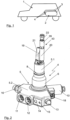
- the tank valve 4 comprises a base body 5, which essentially consists of two sections.
- a first base body section 5.1 is designed in such a way that it protrudes into the respective compressed gas container 3 in the later assembled state of the tank valve 4. In the embodiment shown here, it has a thread designated 6, which is connected to a corresponding thread in a receiving element 7, which in the representation of the Figure 3 is partially indicated, of the pressure gas container 3.
- This first base body section 5.1 also has a Figure 2
- the sealing device indicated consists of one or more sealing rings and/or support rings.
- a second base body section 5.2 is shown in the illustration of the Figure 2 in the lower area of the tank valve 4.
- This second base body section 5.2 is located outside the compressed gas container 3 after the tank valve 4 has been installed, as is shown, for example, in the Figure 3 , in a schematic side view, indicated manner.
- the second base body section 5.2 has several so-called functional subgroups of the tank valve 4.
- the functional subgroups in the second base body section 5.2 comprise an electromagnetically operated pilot valve 9 as a removal valve for removing gas from the compressed gas container 3. It is operated via an electromagnetic coil designated 10, whereby in the illustration of the Figures 2 and 3 only the electromagnetic coil 10 can be seen.
- the pilot valve 9 itself is indicated schematically. Regarding the functionality of such a pilot valve, reference can be made to the explanations in the EN 10 2013 019 978 A1 the applicant should be informed.
- thermally triggered safety valves are known in principle from the general state of the art.
- a screw is used here which has a central hole.
- a solder or a locking body held in place by a solder. If the area of the tank valve 4 or the thermally triggered safety valve 13 heats up beyond the melting temperature of the solder, the through hole in the screw is released and the gas in the interior of the compressed gas container 13 which is in permanent connection with the screw can flow out.
- An alternative to this which is used very frequently in the European and American markets in particular, is a structure in which a valve body is held in position by a glass ampoule containing a slightly boiling liquid.
- the boiling point of the liquid in the glass ampoule is adjusted so that it begins to boil at a critical temperature of the thermally triggered safety valve 13.
- the increase in volume during boiling destroys the glass ampoule and releases the valve body from the valve seat.
- the pressure of the gas in the compressed gas container which is applied to the valve body, moves it into an open position, away from the valve seat, so that the gas can flow out of the compressed gas container 3.
- blow-off line marked 14 which is connected to the interior of the compressed gas container 3 when the thermally triggered safety valve 13 is activated.
- a threaded hole marked 15 in the figures, which is suitable for receiving a screw.
- a so-called blow-off line or venting tube can be easily and reliably installed here. screwed on, for example in the manner described in the German patent application EN 10 2013 015 515 A1 described by the applicant.
- a gas connection 16 can be seen.
- This gas connection can be used, for example, to remove gas from the compressed gas container via the pilot valve 9 and/or to refuel the compressed gas container 3.
- a filter designated 17 is arranged integrated in the gas connection 16, which filter out contaminants in the gas flowing into the compressed gas container 3, in particular when the gas connection 16 is used to refuel the compressed gas container 3.
- a recognizable element in the area of the second base body section 5.2 or in the area of the electromagnetic coil 10 is a plug connection designated 18, via which on the one hand the electromagnetic coil 10 and thus the pilot valve 9 and on the other hand measurement data, for example that of a temperature sensor designated 19, can be transmitted.
- the tank valve 4 has the electrical plug connection 18 as the only electrical connection, so that the wiring of the storage device 2 can be designed accordingly simply and efficiently.
- a slightly curved pipe section 21 can also be seen mounted on it in the direction of the interior of the compressed gas container 3. Its design is selected such that it distributes the inflowing gas into the compressed gas container 3 when the compressed gas container 3 is filled in such a way that the gas is mixed and thus the temperature is reliably measured by the temperature sensor 19.
- An outlet opening 42 of the curved pipe section 21 is ideally narrowed in the flow cross-section compared to the nominal diameter in order to support the formation of a jet of the gas flowing into the compressed gas container 3. This achieves better mixing of the gas with the residual gas inside the compressed gas container, so that a more homogeneous temperature distribution is achieved overall. This benefits the reliable measurement of the temperature by the temperature sensor 19.
- a component designated as 43 is mounted on the first base body section 5.1, which is also referred to below as assembly filter 43.
- This assembly filter comprises a filter 20, as well as a pipe rupture protection device 22 and a check valve 26.
- the pipe rupture protection device 22 and the check valve 26 are some of the functional subgroups which in the embodiment of the Figure 2 are not integrated into the first base body section 5.2, but are mounted on it. The functionality of these two functional subgroups, the pipe rupture protection device 22 and the check valve 26, is described in more detail below using their equally conceivable integrated structure.
- the functional subgroups which are arranged in a protected manner after the tank valve 4 has been installed inside the compressed gas container 3, comprise at least the pipe rupture protection device 22 and a check valve 23 in a refueling line 24, which opens into the pipe section 21.
- a further check valve 26 can be arranged in the extraction path, which has the pipe rupture protection device 22, which ensures that in the event of refueling, the gas flows into the compressed gas container 3 via the refueling line 24 and the pipe section 21, and that in the event of gas being extracted via the pilot valve 9, the flow takes place through the filter 20 and the extraction line 25.
- the check valve 26 is therefore effectively used to select, when the pilot valve 9 is deactivated, whether the gas flows through the refueling line 24 or through the extraction line 25.
- the check valve 26 could therefore also be referred to as a selection valve for the flow path.
- the check valve 26, the pipe rupture protection device 22 and the filter 20 can be integrated as an assembly filter and mounted on the first base body section 5.1 in the direction of the interior of the compressed gas container 3.
- the two valve devices 22, 26 are located in front of the filter 20, so that any particles that may have been rubbed off in the area of the valve devices 22, 26 are retained by the filter 20 and cannot reach the area of the pilot valve 9.
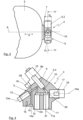
- these components can also be integrated into the base body section 5.1, as shown in the illustration of the Figure 5 is partially indicated.
- a further optional functional subgroup can be seen in the form of a rigid aperture 27 in a line element 28 leading to the thermally triggered safety valve 13, indicated by a dashed line.
- the line element 28 is connected to the interior of the compressed gas container 3 at one end of the first base body section 5.1 without any further valve devices. At its other end, it is connected to the thermally triggered safety valve 13, so that even in the event of a malfunction of another valve device, it is always ensured that the gas flows out of the compressed gas container 3 as desired when the thermally triggered safety valve is activated.
- the alternative representation in Figure 6 shows that in principle the safety valve 13 can also be arranged in the first base body section 5.1 instead of in the second base body section 5.2, for example in the flow direction of the outflowing gas after the orifice 27, as in the illustration of the Figure 6 indicated, or also in the flow direction in front of the orifice 27 if this would be advantageous in terms of the installation space within the first base body section 5.1.
- the safety valve 13 as a functional subgroup can therefore be integrated both in the first base body section 5.1, as shown in the illustration of the Figure 6 can be seen, as well as in the second body section 5.2, as shown in the illustrations of the Figures 2 and 5 is recognizable. In the following, it is therefore mentioned in both construction variants, depending on the design of the respective figure.
- the functional subgroups 13, 22, 23 and, if applicable, 27 and, in addition, the functional subgroup 26 are different from the example according to Figure 2 here arranged in the first base body section 5.1 of the tank valve 4. If damage to the storage device 2 affects individual compressed gas containers 3 and their tank valves 4, this can in particular lead to the tank valve 4 shearing off from the compressed gas container 3. In this case, for example, the second base body section 5.2 would be completely or partially sheared off. Without the compressed gas container 3 itself being damaged, the first functional sub-group 5.1 will typically remain inside the receiving element 7 of the compressed gas container, to which it is screwed.
- the functional sub-groups arranged there 13, 22, 23, 27, 26 are therefore particularly well protected, which is a decisive safety advantage, especially for the safety-relevant functional subgroups 13, 22 and 23.
- the functional subgroups 9, 11, 12, 13, 14, 16, 17 arranged in the second base body section 5.2 as well as the electromagnetic coil 10 corresponding to the pilot valve 9 and cooperating in alignment with it, into which a part of the pilot valve 9 protrudes accordingly, are in terms of their in the representation of the Figure 4 each indicated primary axial orientation, which is indicated by the corresponding axes 9a, 11a, 12a,13a,14a, 16a, in a single plane, namely the one shown in the illustration of the Figure 4 shown section plane IV-IV, which can also be seen from the representation of the Figure 3
- This arrangement of the functional subgroups 9, 11,12, 13, 14, 16, 17 located in the second base body section 5.2 enables an extremely compact arrangement of the entire structure in the axial direction a relative to the axis A, which in the Figures 3 and 5
- the thickness D of the second base body section 5.2 is less than approx.
- the second base body section 5.2 is ideally constructed from an aluminum alloy by forging in one piece with the first base body section 5.1.
- the functional subgroups are then integrated into the base body accordingly.
- the first base body section 5.1 this is done in the representation of the Figure 2 from above, i.e. from the side that will later be inside the pressure gas container 3.
- the other elements are placed in the Figure 4
- the functional sub-assemblies are assembled accordingly in the level shown, for example by screwing the individual functional sub-assemblies as pre-assembled elements into the second base body section 5.2.
- the functional sub-assemblies are typically made from suitable materials, such as stainless steels in particular and, in the area of the sealing seats, possibly also plastics.
- the arrangement in the one level IV-IV which has already been mentioned several times, enables the desired very compact structure to be achieved.
- the representation in the Figure 7 shows again indicated the base body 5 of the tank valve 4 with the first base body section 5.1, which in the assembled state lies inside the compressed gas container and the second base body section 5.2, which typically remains outside the compressed gas container.
- the core of the tank valve 4 is the pilot valve 9 with its electromagnetic coil 10 and a 29 Other functional subgroups include the manual shut-off valve 11, the manual drain valve 12, the thermally triggered safety valve 13, the gas connection 16 and the filter 17.
- the first base section 5.1 contains the pipe rupture protection 22, the check valve 23 in the refueling line 24 and the check valve 26 in the extraction line 25.
- the check valve 26 and the pipe rupture protection device 22 can also be mounted, preferably together with the filter 20, to the first base body section 5.1 on its side facing the interior of the compressed gas container 3 as an assembly filter 43.
- the manual shut-off valve 11 is located between the two and is normally closed, as shown in the illustration of the Figure 7 is open.
- the manual shut-off valve 11 can act accordingly, for example along its axis 11a, on the cross-sectional expansion of the line section 30, for example in that it is designed as a valve seat for a valve body (not shown) of the shut-off valve 11.
- the extraction line 25 and the refueling line 24 also branch off after the manual shut-off valve 11.
- the pipe section 21, the temperature sensor 19 and the filter 20 for the extraction line 25 can also be seen.
- the check valve 26 is located in the extraction line 25, which is connected to the line section 30 via the pilot valve 29, and prevents gas from flowing into the compressed gas tank 3 via the extraction line 25 during refueling.
- the gas would escape from the tank valve 4 via the filter 20 in an area where it would come into very direct contact with the temperature sensor 19.
- the temperature sensor 19, which provides one of the decisive switch-off criteria when refueling the compressed gas tank 3, would then be cooled down unnecessarily, so that in the worst case, refueling would end too early.
- the gas is now extracted in such a way that the check valve 23, supported by the spring indicated, closes.
- the gas then flows into the extraction line 25. It flows via the pipe rupture protection device 22, which is open in the normally state, and the check valve 26, which is open in the extraction case, to the filter 20 and from there to the pilot valve 9.
- the desired amount of gas is achieved by a corresponding electrical control of the electromagnetic coil 10 and via the electrical plug connection 18.
- the desired extraction amount then flows again via the line section 30 and the manual shut-off valve 11, which is open in the normally state, to the gas connection 16 and from there on, for example to a pressure regulator, and then into an internal combustion engine, a fuel cell system, a hot gas turbine or another useful application.
- the manual shut-off valve 11 can be used to manually shut off the tank valve 4. For this purpose, it is separated from its Figure 7 shown open normal position to the other position and thus blocks the line section 30 and thus the extraction path as well as the refueling line 24 by separating it from the gas connection 16. This can be used sensibly, for example, in the context of maintenance, a malfunction or the like.
- the manual drain valve remains connected to the gas connection 16 via the line section 31. It is shown in the illustration of the Figure 7 shown in its normal closed position. At its other end it is connected to the line element 28, which connects the interior of the pressure gas container 3 with the thermally triggered Safety valve 13 - which, as mentioned, could also be arranged in the first base body section 5.1 - and which can have the mentioned rigid aperture 27. If the pressure gas container 3 is now to be emptied, the manual emptying valve can be moved from its Figure 7 shown closed position to the open position. The gas then flows out via the line element 28 and the line element 31 via the gas connection 16.
- thermally triggered safety valve 13 Another conceivable scenario would be the triggering of the thermally triggered safety valve 13. If, for example, a glass ampoule containing a slightly boiling liquid is destroyed in the thermally triggered safety valve 13, then, as already described above, the valve changes from its Figure 7 shown normally closed position to the other open position. The gas can then flow to the blow-off line 14 via the line element 28. In this area, a further line element, a so-called venting tube, is typically connected, which discharges the gas into a non-critical area, particularly in vehicle applications. In this regard, reference can be made to the German application of the applicant mentioned above.
Landscapes
- Engineering & Computer Science (AREA)
- General Engineering & Computer Science (AREA)
- Mechanical Engineering (AREA)
- Filling Or Discharging Of Gas Storage Vessels (AREA)
Applications Claiming Priority (2)
| Application Number | Priority Date | Filing Date | Title |
|---|---|---|---|
| DE102016008107.4A DE102016008107A1 (de) | 2016-07-01 | 2016-07-01 | Tankventil |
| PCT/EP2017/000764 WO2018001560A1 (de) | 2016-07-01 | 2017-06-28 | Tankventil |
Publications (3)
| Publication Number | Publication Date |
|---|---|
| EP3479007A1 EP3479007A1 (de) | 2019-05-08 |
| EP3479007B1 true EP3479007B1 (de) | 2024-07-31 |
| EP3479007C0 EP3479007C0 (de) | 2024-07-31 |
Family
ID=59258173
Family Applications (1)
| Application Number | Title | Priority Date | Filing Date |
|---|---|---|---|
| EP17734241.7A Active EP3479007B1 (de) | 2016-07-01 | 2017-06-28 | Tankventil |
Country Status (6)
| Country | Link |
|---|---|
| US (1) | US10948087B2 (enExample) |
| EP (1) | EP3479007B1 (enExample) |
| JP (1) | JP6896777B2 (enExample) |
| CN (1) | CN109416152B (enExample) |
| DE (1) | DE102016008107A1 (enExample) |
| WO (1) | WO2018001560A1 (enExample) |
Families Citing this family (40)
| Publication number | Priority date | Publication date | Assignee | Title |
|---|---|---|---|---|
| DE102018221600A1 (de) * | 2018-12-13 | 2020-06-18 | Robert Bosch Gmbh | Verfahren zum Betreiben einer Tankvorrichtung zur Speicherung von verdichteten Fluiden |
| AT16929U1 (de) | 2019-05-28 | 2020-12-15 | Zieger Dipl Ing Andreas | Kombinationsventil |
| CN110630786A (zh) * | 2019-09-12 | 2019-12-31 | 江苏国富氢能技术装备有限公司 | 一种高压瓶口阀的进出气结构 |
| AT16988U1 (de) | 2019-09-27 | 2021-01-15 | Zieger Dipl Ing Andreas | Kombinationsventil |
| CN112918283B (zh) * | 2019-12-05 | 2022-04-22 | 未势能源科技有限公司 | 用于车辆的储气瓶及具有其的车辆 |
| DE102019220512A1 (de) * | 2019-12-23 | 2021-06-24 | Robert Bosch Gmbh | Verfahren zur Herstellung einer Komponente zur Speicherung oder Verteilung von Druckgas und Komponente zur Speicherung oder Verteilung von Druckgas |
| DE102020200679A1 (de) | 2020-01-22 | 2021-07-22 | Robert Bosch Gesellschaft mit beschränkter Haftung | Verfahren zum Öffnen einer Ventilanordnung für einen Treibstofftank |
| DE102020201170A1 (de) * | 2020-01-31 | 2021-08-05 | Robert Bosch Gesellschaft mit beschränkter Haftung | Ventilsystem und Druckspeicher mit einem Ventilsystem |
| DE102020201172A1 (de) * | 2020-01-31 | 2021-08-05 | Robert Bosch Gesellschaft mit beschränkter Haftung | Vorrichtung zum Speichern von Druckgas, Fahrzeug |
| IT202000008932A1 (it) | 2020-04-24 | 2021-10-24 | Omb Saleri S P A | Valvola multifunzione per sistemi di autotrazione a celle combustibile |
| JP2021173355A (ja) * | 2020-04-27 | 2021-11-01 | 川崎重工業株式会社 | タンクバルブ装置、及びバルブブロック |
| IT202000009409A1 (it) * | 2020-04-29 | 2021-10-29 | Omb Saleri S P A Soc Benefit | Gruppo bombole per un sistema per autotrazione a celle combustibile ad idrogeno |
| DE102020207261A1 (de) * | 2020-06-10 | 2021-12-16 | Argo Gmbh | Thermische Druckentlastungsvorrichtung (TPRD), Gasdruckspeicher und Gasdruckspeichersystem mit TPRD und Verfahren zur thermischen Überdruckabsicherung |
| DE102020207253A1 (de) * | 2020-06-10 | 2021-12-16 | Argo Gmbh | Ventileinrichtung, Intankventil und Gasdruckspeichersystem, insbesondere für Brennstoffzellensysteme, sowie Verfahren zum Detektieren einer Leckage |
| DE102020123037A1 (de) | 2020-09-03 | 2022-03-03 | Bayerische Motoren Werke Aktiengesellschaft | Druckbehälter, Druckbehältersystem und Kraftfahrzeug mit Brennstoffleiste |
| WO2022099336A1 (de) * | 2020-11-10 | 2022-05-19 | Cryoshelter Gmbh | System umfassend einen kryobehälter und einen thermischen siphon |
| CN113503467B (zh) * | 2021-07-08 | 2023-07-25 | 亚普汽车部件(开封)有限公司 | 一种车用高压气瓶阀 |
| DE102021207716A1 (de) * | 2021-07-20 | 2023-01-26 | Argo Gmbh | Befüllvorrichtung für Wasserstofftanks, Wasserstofftank aufweisend die Befüllvorrichtung sowie Verfahren zur Befüllung eines Wasserstofftanks |
| EP4170763A1 (de) * | 2021-10-20 | 2023-04-26 | Robert Bosch GmbH | Ableitungs- und befüllsystem |
| IT202100032546A1 (it) * | 2021-12-23 | 2023-06-23 | Omb Saleri S P A Soc Benefit | Gruppo connettore per una valvola multifunzione di un impianto per autotrazione a celle combustibili |
| KR102457115B1 (ko) * | 2022-05-13 | 2022-10-20 | 주식회사 네오스펙 | 고압탱크용 일체형 충전 및 해압 밸브 |
| CN114777017B (zh) * | 2022-05-20 | 2024-07-30 | 亚普汽车部件(开封)有限公司 | 一种车用气体瓶阀及生产方法 |
| DE102022208213A1 (de) * | 2022-08-08 | 2024-02-08 | Robert Bosch Gesellschaft mit beschränkter Haftung | Verfahren zum Befüllen eines Brenngastanks mit Brenngas, Brenngastank sowie Brenngastanksystem |
| DE102022208209A1 (de) * | 2022-08-08 | 2024-02-08 | Robert Bosch Gesellschaft mit beschränkter Haftung | Brenngastank sowie Brenngastanksystem |
| DE102022208212A1 (de) * | 2022-08-08 | 2024-02-08 | Robert Bosch Gesellschaft mit beschränkter Haftung | Verfahren zum Befüllen eines Brenngastanks mit Brenngas, Brenngastank sowie Brenngastanksystem |
| DE102022208214A1 (de) * | 2022-08-08 | 2024-02-08 | Robert Bosch Gesellschaft mit beschränkter Haftung | Verfahren zum Befüllen eines Brenngastanks mit Brenngas, Brenngastank sowie Brenngastanksystem |
| DE102022208553A1 (de) * | 2022-08-18 | 2024-02-29 | Robert Bosch Gesellschaft mit beschränkter Haftung | Tanksystem für ein wasserstoffbetriebenes Fahrzeug, Brennstoffzellenanordnung, Wasserstoff-Verbrennungsmotorsystem, brennstoffzellenbetriebenes Fahrzeug, wasserstoffbetriebenes Fahrzeug |
| DE102022123005A1 (de) * | 2022-09-09 | 2024-03-14 | Bayerische Motoren Werke Aktiengesellschaft | Ventilbaugruppe, Druckbehältersystem, Kraftfahrzeug und Herstellverfahren für ein Druckbehältersystem |
| DE102022211707A1 (de) * | 2022-11-07 | 2024-05-08 | Robert Bosch Gesellschaft mit beschränkter Haftung | Ventilbaugruppe für einen Brenngastank, Brenngastank mit Ventilbaugruppe |
| DE102022211715A1 (de) * | 2022-11-07 | 2024-05-08 | Robert Bosch Gesellschaft mit beschränkter Haftung | Ventilbaugruppe für einen Brenngastank, Brenngastank mit Ventilbaugruppe |
| DE102022211716A1 (de) * | 2022-11-07 | 2024-05-08 | Robert Bosch Gesellschaft mit beschränkter Haftung | Ventilbaugruppe für einen Brenngastank, Brenngastank mit Ventilbaugruppe |
| DE102022132218A1 (de) * | 2022-12-05 | 2024-06-06 | Bayerische Motoren Werke Aktiengesellschaft | Druckbehältersystem mit einer Druckbehälterbaugruppe |
| DE102023202527A1 (de) * | 2023-03-21 | 2024-09-26 | Robert Bosch Gesellschaft mit beschränkter Haftung | Ventilbaugruppe für einen Brenngastank, Brenngastank mit Ventilbaugruppe sowie Brenngastanksystem |
| DE102023202528A1 (de) * | 2023-03-21 | 2024-09-26 | Robert Bosch Gesellschaft mit beschränkter Haftung | Ventilbaugruppe für einen Brenngastank, Brenngastank mit Ventilbaugruppe sowie Brenngastanksystem |
| DE102023202526A1 (de) * | 2023-03-21 | 2024-09-26 | Robert Bosch Gesellschaft mit beschränkter Haftung | Ventilbaugruppe für einen Brenngastank, Brenngastank mit Ventilbaugruppe sowie Brenngastanksystem |
| DE102023210738A1 (de) | 2023-10-30 | 2025-04-30 | Robert Bosch Gesellschaft mit beschränkter Haftung | Betriebsverfahren zum Betreiben eines Wasserstofftanksystems und Wasserstofftanksystem |
| DE102023213009A1 (de) * | 2023-12-20 | 2025-06-26 | Robert Bosch Gesellschaft mit beschränkter Haftung | Betankungsverfahren und Tanksystem |
| FR3158136A1 (fr) * | 2024-01-08 | 2025-07-11 | L'air Liquide, Societe Anonyme Pour L'etude Et L'exploitation Des Procedes Georges Claude | Injecteur pour un réservoir de gaz, et réservoir équipé d’un tel injecteur. |
| DE102024200649A1 (de) | 2024-01-25 | 2025-07-31 | Robert Bosch Gesellschaft mit beschränkter Haftung | Ventilbaugruppe für einen Brenngastank, Brenngastank sowie Brenngastanksystem |
| DE102024200926A1 (de) | 2024-02-01 | 2025-08-07 | Robert Bosch Gesellschaft mit beschränkter Haftung | Ventilbaugruppe für einen Brenngastank, Brenngastank, Brenngastanksystem sowie Verwendung für ein Sitzelement |
Citations (1)
| Publication number | Priority date | Publication date | Assignee | Title |
|---|---|---|---|---|
| EP2857727A1 (en) * | 2012-06-04 | 2015-04-08 | Youngdo Ind. Co., Ltd. | Fluid control valve assembly |
Family Cites Families (22)
| Publication number | Priority date | Publication date | Assignee | Title |
|---|---|---|---|---|
| US5193580A (en) | 1991-05-30 | 1993-03-16 | Wass Lloyd G | Crash proof solenoid controlled valve with manual override valve |
| DE4334182A1 (de) * | 1993-10-07 | 1995-04-13 | Flow Instr & Engineering Gmbh | Absperrvorrichtung, insbesondere Ventil |
| US5941268A (en) * | 1996-08-29 | 1999-08-24 | Ross, Jr.; Donald P. | Tank safety valve |
| JP2943980B2 (ja) * | 1997-07-24 | 1999-08-30 | 本田技研工業株式会社 | ガス燃料用配管装置 |
| DE19852471C2 (de) | 1998-11-13 | 2003-02-20 | Messer Cutting & Welding Ag | Gasentnahmesystem mit austauschbarem Anschluß |
| DE10065268C1 (de) | 2000-12-29 | 2002-08-29 | Novars Ges Fuer Neue Technolog | Druckbehälter mit integrierter Steuerung eines komprimierten Mediums |
| US6911065B2 (en) | 2002-12-26 | 2005-06-28 | Matheson Tri-Gas, Inc. | Method and system for supplying high purity fluid |
| DE10361781B4 (de) | 2003-10-21 | 2005-09-15 | Klaus Dipl.-Ing. Perthel | Elektromagnetisches Ventil |
| DE10362052A1 (de) | 2003-10-21 | 2005-09-08 | Klaus Dipl.-Ing. Perthel | Rückschlagventil bzw. thermische Sicherheitseinrichtung, insbesondere für ein elektromagnetisches Ventil |
| US7152617B1 (en) * | 2004-05-28 | 2006-12-26 | Randal Wade Crawford | High pressure release safety valve assembly |
| CN100458264C (zh) * | 2004-08-23 | 2009-02-04 | 丰田自动车株式会社 | 高压罐以及阀门组件 |
| JP4579657B2 (ja) | 2004-11-17 | 2010-11-10 | 株式会社ジェイテクト | 弁装置の固定構造及びマニュアル弁 |
| JP4496477B2 (ja) * | 2005-03-01 | 2010-07-07 | トヨタ自動車株式会社 | ガス容器用バルブアッセンブリ |
| US20080289700A1 (en) | 2007-05-24 | 2008-11-27 | Masingale Levi D | High pressure safety valve, system and method |
| JP4984329B2 (ja) | 2008-01-16 | 2012-07-25 | トヨタ自動車株式会社 | 高圧タンク用のバルブ装置および燃料電池システム |
| JP5159360B2 (ja) * | 2008-02-19 | 2013-03-06 | 古河スカイ株式会社 | 高圧水素ガス用アルミニウム合金及び高圧水素ガス用アルミニウム合金クラッド材 |
| JP5217625B2 (ja) * | 2008-05-22 | 2013-06-19 | 株式会社ジェイテクト | 弁装置 |
| DE102009046004A1 (de) | 2009-10-26 | 2011-04-28 | Robert Bosch Gmbh | Ventil für einen Gastank |
| CN202972091U (zh) | 2012-11-13 | 2013-06-05 | 杨柳青 | 液化气遇热自动关闭安全阀 |
| JP5873451B2 (ja) | 2013-02-26 | 2016-03-01 | 川崎重工業株式会社 | 弁装置 |
| DE102013015515A1 (de) | 2013-09-19 | 2015-03-19 | Daimler Ag | Vorrichtung zum Ableiten von Gas |
| DE102013019877B4 (de) | 2013-11-26 | 2025-01-09 | Cellcentric Gmbh & Co. Kg | Entnahmeventil |
-
2016
- 2016-07-01 DE DE102016008107.4A patent/DE102016008107A1/de active Pending
-
2017
- 2017-06-28 CN CN201780040735.9A patent/CN109416152B/zh active Active
- 2017-06-28 JP JP2018567720A patent/JP6896777B2/ja active Active
- 2017-06-28 WO PCT/EP2017/000764 patent/WO2018001560A1/de not_active Ceased
- 2017-06-28 US US16/314,049 patent/US10948087B2/en active Active
- 2017-06-28 EP EP17734241.7A patent/EP3479007B1/de active Active
Patent Citations (1)
| Publication number | Priority date | Publication date | Assignee | Title |
|---|---|---|---|---|
| EP2857727A1 (en) * | 2012-06-04 | 2015-04-08 | Youngdo Ind. Co., Ltd. | Fluid control valve assembly |
Also Published As
| Publication number | Publication date |
|---|---|
| US20190170260A1 (en) | 2019-06-06 |
| CN109416152B (zh) | 2021-11-26 |
| CN109416152A (zh) | 2019-03-01 |
| JP6896777B2 (ja) | 2021-06-30 |
| WO2018001560A1 (de) | 2018-01-04 |
| US10948087B2 (en) | 2021-03-16 |
| JP2019521296A (ja) | 2019-07-25 |
| DE102016008107A1 (de) | 2018-01-04 |
| EP3479007A1 (de) | 2019-05-08 |
| EP3479007C0 (de) | 2024-07-31 |
Similar Documents
| Publication | Publication Date | Title |
|---|---|---|
| EP3479007B1 (de) | Tankventil | |
| EP3479008B1 (de) | Tankventil | |
| DE102016008059A1 (de) | Tankventil | |
| EP3803191B1 (de) | Tankvorrichtung zur temperaturdruckentlastung eines brennstoffzellentanks | |
| EP4097390A1 (de) | Vorrichtung zum speichern von druckgas, fahrzeug | |
| DE112010000058T5 (de) | Ventilsystem für Fahrzeug-Hochdrucktank | |
| DE102014000616B4 (de) | Thermisch auslösendes Sicherheitsventil | |
| DE102016008079A1 (de) | Tankventil | |
| DE10065268C1 (de) | Druckbehälter mit integrierter Steuerung eines komprimierten Mediums | |
| WO2005040654A2 (de) | Elektromagnetisches ventil | |
| DE202011108934U1 (de) | Vorrichtung zum Speichern von Gas unter hohem Druck | |
| DE102015015004A1 (de) | Ventileinrichtung | |
| DE102009039079A1 (de) | Tankanordnung | |
| DE102020108176A1 (de) | Brennstoffversorgungssystem und Kraftfahrzeug | |
| WO2021089294A1 (de) | Tankvorrichtung zur temperaturdruckentlastung eines brennstoffzellentanks | |
| DE102011114722A1 (de) | Druckgasbehälter mit einem Ventil | |
| DE102013210335A1 (de) | Galvanische Zelle und Batteriesystem mit wenigstens einer galvanischen Zelle | |
| WO2013045022A2 (de) | Vorrichtung zum speichern von gas unter hohem druck | |
| DE102019120241A1 (de) | Druckbehälteranordnung | |
| EP3236133A1 (de) | Tanksystem | |
| DE102006004781B4 (de) | Expansionsventil für eine Klimaanlage | |
| DE102021104334A1 (de) | Anschlusselement, Druckbehälterbaugruppe und Kraftfahrzeug | |
| WO2021089288A1 (de) | Tankvorrichtung zur temperaturdruckentlastung eines brennstoffzellentanks | |
| DE102016008035A1 (de) | Tankventil | |
| DE102016008106A1 (de) | Tankventil |
Legal Events
| Date | Code | Title | Description |
|---|---|---|---|
| STAA | Information on the status of an ep patent application or granted ep patent |
Free format text: STATUS: UNKNOWN |
|
| STAA | Information on the status of an ep patent application or granted ep patent |
Free format text: STATUS: THE INTERNATIONAL PUBLICATION HAS BEEN MADE |
|
| PUAI | Public reference made under article 153(3) epc to a published international application that has entered the european phase |
Free format text: ORIGINAL CODE: 0009012 |
|
| STAA | Information on the status of an ep patent application or granted ep patent |
Free format text: STATUS: REQUEST FOR EXAMINATION WAS MADE |
|
| 17P | Request for examination filed |
Effective date: 20181220 |
|
| AK | Designated contracting states |
Kind code of ref document: A1 Designated state(s): AL AT BE BG CH CY CZ DE DK EE ES FI FR GB GR HR HU IE IS IT LI LT LU LV MC MK MT NL NO PL PT RO RS SE SI SK SM TR |
|
| AX | Request for extension of the european patent |
Extension state: BA ME |
|
| DAV | Request for validation of the european patent (deleted) | ||
| DAX | Request for extension of the european patent (deleted) | ||
| RAP1 | Party data changed (applicant data changed or rights of an application transferred) |
Owner name: DAIMLER AG |
|
| RAP1 | Party data changed (applicant data changed or rights of an application transferred) |
Owner name: 2O CELLCENTRIC GMBH & CO. KG |
|
| RAP3 | Party data changed (applicant data changed or rights of an application transferred) |
Owner name: CELLCENTRIC GMBH & CO. KG |
|
| STAA | Information on the status of an ep patent application or granted ep patent |
Free format text: STATUS: EXAMINATION IS IN PROGRESS |
|
| 17Q | First examination report despatched |
Effective date: 20211105 |
|
| GRAP | Despatch of communication of intention to grant a patent |
Free format text: ORIGINAL CODE: EPIDOSNIGR1 |
|
| STAA | Information on the status of an ep patent application or granted ep patent |
Free format text: STATUS: GRANT OF PATENT IS INTENDED |
|
| INTG | Intention to grant announced |
Effective date: 20240223 |
|
| INTG | Intention to grant announced |
Effective date: 20240223 |
|
| GRAS | Grant fee paid |
Free format text: ORIGINAL CODE: EPIDOSNIGR3 |
|
| GRAA | (expected) grant |
Free format text: ORIGINAL CODE: 0009210 |
|
| STAA | Information on the status of an ep patent application or granted ep patent |
Free format text: STATUS: THE PATENT HAS BEEN GRANTED |
|
| AK | Designated contracting states |
Kind code of ref document: B1 Designated state(s): AL AT BE BG CH CY CZ DE DK EE ES FI FR GB GR HR HU IE IS IT LI LT LU LV MC MK MT NL NO PL PT RO RS SE SI SK SM TR |
|
| REG | Reference to a national code |
Ref country code: CH Ref legal event code: EP Ref country code: GB Ref legal event code: FG4D Free format text: NOT ENGLISH |
|
| REG | Reference to a national code |
Ref country code: DE Ref legal event code: R096 Ref document number: 502017016308 Country of ref document: DE |
|
| REG | Reference to a national code |
Ref country code: IE Ref legal event code: FG4D Free format text: LANGUAGE OF EP DOCUMENT: GERMAN |
|
| U01 | Request for unitary effect filed |
Effective date: 20240731 |
|
| U07 | Unitary effect registered |
Designated state(s): AT BE BG DE DK EE FI FR IT LT LU LV MT NL PT SE SI Effective date: 20240822 |
|
| PG25 | Lapsed in a contracting state [announced via postgrant information from national office to epo] |
Ref country code: NO Free format text: LAPSE BECAUSE OF FAILURE TO SUBMIT A TRANSLATION OF THE DESCRIPTION OR TO PAY THE FEE WITHIN THE PRESCRIBED TIME-LIMIT Effective date: 20241031 |
|
| PG25 | Lapsed in a contracting state [announced via postgrant information from national office to epo] |
Ref country code: GR Free format text: LAPSE BECAUSE OF FAILURE TO SUBMIT A TRANSLATION OF THE DESCRIPTION OR TO PAY THE FEE WITHIN THE PRESCRIBED TIME-LIMIT Effective date: 20241101 Ref country code: PL Free format text: LAPSE BECAUSE OF FAILURE TO SUBMIT A TRANSLATION OF THE DESCRIPTION OR TO PAY THE FEE WITHIN THE PRESCRIBED TIME-LIMIT Effective date: 20240731 |
|
| PG25 | Lapsed in a contracting state [announced via postgrant information from national office to epo] |
Ref country code: IS Free format text: LAPSE BECAUSE OF FAILURE TO SUBMIT A TRANSLATION OF THE DESCRIPTION OR TO PAY THE FEE WITHIN THE PRESCRIBED TIME-LIMIT Effective date: 20241130 |
|
| PG25 | Lapsed in a contracting state [announced via postgrant information from national office to epo] |
Ref country code: HR Free format text: LAPSE BECAUSE OF FAILURE TO SUBMIT A TRANSLATION OF THE DESCRIPTION OR TO PAY THE FEE WITHIN THE PRESCRIBED TIME-LIMIT Effective date: 20240731 |
|
| PG25 | Lapsed in a contracting state [announced via postgrant information from national office to epo] |
Ref country code: ES Free format text: LAPSE BECAUSE OF FAILURE TO SUBMIT A TRANSLATION OF THE DESCRIPTION OR TO PAY THE FEE WITHIN THE PRESCRIBED TIME-LIMIT Effective date: 20240731 Ref country code: RS Free format text: LAPSE BECAUSE OF FAILURE TO SUBMIT A TRANSLATION OF THE DESCRIPTION OR TO PAY THE FEE WITHIN THE PRESCRIBED TIME-LIMIT Effective date: 20241031 |
|
| PG25 | Lapsed in a contracting state [announced via postgrant information from national office to epo] |
Ref country code: RS Free format text: LAPSE BECAUSE OF FAILURE TO SUBMIT A TRANSLATION OF THE DESCRIPTION OR TO PAY THE FEE WITHIN THE PRESCRIBED TIME-LIMIT Effective date: 20241031 Ref country code: PL Free format text: LAPSE BECAUSE OF FAILURE TO SUBMIT A TRANSLATION OF THE DESCRIPTION OR TO PAY THE FEE WITHIN THE PRESCRIBED TIME-LIMIT Effective date: 20240731 Ref country code: NO Free format text: LAPSE BECAUSE OF FAILURE TO SUBMIT A TRANSLATION OF THE DESCRIPTION OR TO PAY THE FEE WITHIN THE PRESCRIBED TIME-LIMIT Effective date: 20241031 Ref country code: IS Free format text: LAPSE BECAUSE OF FAILURE TO SUBMIT A TRANSLATION OF THE DESCRIPTION OR TO PAY THE FEE WITHIN THE PRESCRIBED TIME-LIMIT Effective date: 20241130 Ref country code: HR Free format text: LAPSE BECAUSE OF FAILURE TO SUBMIT A TRANSLATION OF THE DESCRIPTION OR TO PAY THE FEE WITHIN THE PRESCRIBED TIME-LIMIT Effective date: 20240731 Ref country code: GR Free format text: LAPSE BECAUSE OF FAILURE TO SUBMIT A TRANSLATION OF THE DESCRIPTION OR TO PAY THE FEE WITHIN THE PRESCRIBED TIME-LIMIT Effective date: 20241101 Ref country code: ES Free format text: LAPSE BECAUSE OF FAILURE TO SUBMIT A TRANSLATION OF THE DESCRIPTION OR TO PAY THE FEE WITHIN THE PRESCRIBED TIME-LIMIT Effective date: 20240731 |
|
| U1N | Appointed representative for the unitary patent procedure changed after the registration of the unitary effect |
Representative=s name: PLATZOEDER, MICHAEL CHRISTIAN; DE |
|
| U1N | Appointed representative for the unitary patent procedure changed after the registration of the unitary effect |
Representative=s name: PLATZOEDER PATENTANWALTSGESELLSCHAFT MBH; DE |
|
| PG25 | Lapsed in a contracting state [announced via postgrant information from national office to epo] |
Ref country code: SM Free format text: LAPSE BECAUSE OF FAILURE TO SUBMIT A TRANSLATION OF THE DESCRIPTION OR TO PAY THE FEE WITHIN THE PRESCRIBED TIME-LIMIT Effective date: 20240731 |
|
| PG25 | Lapsed in a contracting state [announced via postgrant information from national office to epo] |
Ref country code: CZ Free format text: LAPSE BECAUSE OF FAILURE TO SUBMIT A TRANSLATION OF THE DESCRIPTION OR TO PAY THE FEE WITHIN THE PRESCRIBED TIME-LIMIT Effective date: 20240731 |
|
| PG25 | Lapsed in a contracting state [announced via postgrant information from national office to epo] |
Ref country code: SK Free format text: LAPSE BECAUSE OF FAILURE TO SUBMIT A TRANSLATION OF THE DESCRIPTION OR TO PAY THE FEE WITHIN THE PRESCRIBED TIME-LIMIT Effective date: 20240731 |
|
| PLBE | No opposition filed within time limit |
Free format text: ORIGINAL CODE: 0009261 |
|
| STAA | Information on the status of an ep patent application or granted ep patent |
Free format text: STATUS: NO OPPOSITION FILED WITHIN TIME LIMIT |
|
| 26N | No opposition filed |
Effective date: 20250501 |
|
| PGFP | Annual fee paid to national office [announced via postgrant information from national office to epo] |
Ref country code: GB Payment date: 20250620 Year of fee payment: 9 |
|
| U20 | Renewal fee for the european patent with unitary effect paid |
Year of fee payment: 9 Effective date: 20250623 |