EP3479007B1 - Tank valve - Google Patents
Tank valve Download PDFInfo
- Publication number
- EP3479007B1 EP3479007B1 EP17734241.7A EP17734241A EP3479007B1 EP 3479007 B1 EP3479007 B1 EP 3479007B1 EP 17734241 A EP17734241 A EP 17734241A EP 3479007 B1 EP3479007 B1 EP 3479007B1
- Authority
- EP
- European Patent Office
- Prior art keywords
- valve
- base body
- body section
- tank
- compressed gas
- Prior art date
- Legal status (The legal status is an assumption and is not a legal conclusion. Google has not performed a legal analysis and makes no representation as to the accuracy of the status listed.)
- Active
Links
- 239000007789 gas Substances 0.000 claims description 154
- 238000000605 extraction Methods 0.000 claims description 22
- 239000000446 fuel Substances 0.000 claims description 10
- 238000009434 installation Methods 0.000 claims description 8
- VNWKTOKETHGBQD-UHFFFAOYSA-N methane Chemical compound C VNWKTOKETHGBQD-UHFFFAOYSA-N 0.000 claims description 8
- 239000001257 hydrogen Substances 0.000 claims description 7
- 229910052739 hydrogen Inorganic materials 0.000 claims description 7
- UFHFLCQGNIYNRP-UHFFFAOYSA-N Hydrogen Chemical compound [H][H] UFHFLCQGNIYNRP-UHFFFAOYSA-N 0.000 claims description 5
- 229910000838 Al alloy Inorganic materials 0.000 claims description 4
- 239000003345 natural gas Substances 0.000 claims description 4
- 238000005242 forging Methods 0.000 claims description 2
- 230000001960 triggered effect Effects 0.000 description 17
- 230000008901 benefit Effects 0.000 description 8
- 238000003860 storage Methods 0.000 description 7
- 238000011161 development Methods 0.000 description 6
- 230000018109 developmental process Effects 0.000 description 6
- 238000013461 design Methods 0.000 description 5
- 239000003708 ampul Substances 0.000 description 4
- 238000009835 boiling Methods 0.000 description 4
- 238000010276 construction Methods 0.000 description 4
- 239000011521 glass Substances 0.000 description 4
- 239000000463 material Substances 0.000 description 4
- 238000007789 sealing Methods 0.000 description 4
- 238000000429 assembly Methods 0.000 description 3
- 239000007788 liquid Substances 0.000 description 3
- 229910000679 solder Inorganic materials 0.000 description 3
- 238000002485 combustion reaction Methods 0.000 description 2
- 230000001419 dependent effect Effects 0.000 description 2
- 150000002431 hydrogen Chemical class 0.000 description 2
- 230000010354 integration Effects 0.000 description 2
- 230000007257 malfunction Effects 0.000 description 2
- 238000004519 manufacturing process Methods 0.000 description 2
- 238000005259 measurement Methods 0.000 description 2
- 238000010008 shearing Methods 0.000 description 2
- 238000013022 venting Methods 0.000 description 2
- 229910000831 Steel Inorganic materials 0.000 description 1
- XAGFODPZIPBFFR-UHFFFAOYSA-N aluminium Chemical compound [Al] XAGFODPZIPBFFR-UHFFFAOYSA-N 0.000 description 1
- 229910052782 aluminium Inorganic materials 0.000 description 1
- 230000004323 axial length Effects 0.000 description 1
- 230000015572 biosynthetic process Effects 0.000 description 1
- 239000000356 contaminant Substances 0.000 description 1
- 230000007547 defect Effects 0.000 description 1
- 230000006735 deficit Effects 0.000 description 1
- 238000010586 diagram Methods 0.000 description 1
- 238000009826 distribution Methods 0.000 description 1
- 238000005553 drilling Methods 0.000 description 1
- 230000002349 favourable effect Effects 0.000 description 1
- 239000012530 fluid Substances 0.000 description 1
- 238000012423 maintenance Methods 0.000 description 1
- 238000002844 melting Methods 0.000 description 1
- 230000008018 melting Effects 0.000 description 1
- 239000007769 metal material Substances 0.000 description 1
- 238000002156 mixing Methods 0.000 description 1
- 239000002245 particle Substances 0.000 description 1
- 239000004033 plastic Substances 0.000 description 1
- 229920003023 plastic Polymers 0.000 description 1
- 230000000717 retained effect Effects 0.000 description 1
- 229910001220 stainless steel Inorganic materials 0.000 description 1
- 239000010959 steel Substances 0.000 description 1
Images


Classifications
-
- F—MECHANICAL ENGINEERING; LIGHTING; HEATING; WEAPONS; BLASTING
- F16—ENGINEERING ELEMENTS AND UNITS; GENERAL MEASURES FOR PRODUCING AND MAINTAINING EFFECTIVE FUNCTIONING OF MACHINES OR INSTALLATIONS; THERMAL INSULATION IN GENERAL
- F16K—VALVES; TAPS; COCKS; ACTUATING-FLOATS; DEVICES FOR VENTING OR AERATING
- F16K1/00—Lift valves or globe valves, i.e. cut-off apparatus with closure members having at least a component of their opening and closing motion perpendicular to the closing faces
- F16K1/30—Lift valves or globe valves, i.e. cut-off apparatus with closure members having at least a component of their opening and closing motion perpendicular to the closing faces specially adapted for pressure containers
- F16K1/301—Lift valves or globe valves, i.e. cut-off apparatus with closure members having at least a component of their opening and closing motion perpendicular to the closing faces specially adapted for pressure containers only shut-off valves, i.e. valves without additional means
- F16K1/303—Lift valves or globe valves, i.e. cut-off apparatus with closure members having at least a component of their opening and closing motion perpendicular to the closing faces specially adapted for pressure containers only shut-off valves, i.e. valves without additional means with a valve member, e.g. stem or shaft, passing through the seat
-
- F—MECHANICAL ENGINEERING; LIGHTING; HEATING; WEAPONS; BLASTING
- F17—STORING OR DISTRIBUTING GASES OR LIQUIDS
- F17C—VESSELS FOR CONTAINING OR STORING COMPRESSED, LIQUEFIED OR SOLIDIFIED GASES; FIXED-CAPACITY GAS-HOLDERS; FILLING VESSELS WITH, OR DISCHARGING FROM VESSELS, COMPRESSED, LIQUEFIED, OR SOLIDIFIED GASES
- F17C13/00—Details of vessels or of the filling or discharging of vessels
- F17C13/04—Arrangement or mounting of valves
-
- F—MECHANICAL ENGINEERING; LIGHTING; HEATING; WEAPONS; BLASTING
- F17—STORING OR DISTRIBUTING GASES OR LIQUIDS
- F17C—VESSELS FOR CONTAINING OR STORING COMPRESSED, LIQUEFIED OR SOLIDIFIED GASES; FIXED-CAPACITY GAS-HOLDERS; FILLING VESSELS WITH, OR DISCHARGING FROM VESSELS, COMPRESSED, LIQUEFIED, OR SOLIDIFIED GASES
- F17C2201/00—Vessel construction, in particular geometry, arrangement or size
- F17C2201/01—Shape
- F17C2201/0104—Shape cylindrical
- F17C2201/0109—Shape cylindrical with exteriorly curved end-piece
-
- F—MECHANICAL ENGINEERING; LIGHTING; HEATING; WEAPONS; BLASTING
- F17—STORING OR DISTRIBUTING GASES OR LIQUIDS
- F17C—VESSELS FOR CONTAINING OR STORING COMPRESSED, LIQUEFIED OR SOLIDIFIED GASES; FIXED-CAPACITY GAS-HOLDERS; FILLING VESSELS WITH, OR DISCHARGING FROM VESSELS, COMPRESSED, LIQUEFIED, OR SOLIDIFIED GASES
- F17C2201/00—Vessel construction, in particular geometry, arrangement or size
- F17C2201/05—Size
- F17C2201/056—Small (<1 m3)
-
- F—MECHANICAL ENGINEERING; LIGHTING; HEATING; WEAPONS; BLASTING
- F17—STORING OR DISTRIBUTING GASES OR LIQUIDS
- F17C—VESSELS FOR CONTAINING OR STORING COMPRESSED, LIQUEFIED OR SOLIDIFIED GASES; FIXED-CAPACITY GAS-HOLDERS; FILLING VESSELS WITH, OR DISCHARGING FROM VESSELS, COMPRESSED, LIQUEFIED, OR SOLIDIFIED GASES
- F17C2201/00—Vessel construction, in particular geometry, arrangement or size
- F17C2201/05—Size
- F17C2201/058—Size portable (<30 l)
-
- F—MECHANICAL ENGINEERING; LIGHTING; HEATING; WEAPONS; BLASTING
- F17—STORING OR DISTRIBUTING GASES OR LIQUIDS
- F17C—VESSELS FOR CONTAINING OR STORING COMPRESSED, LIQUEFIED OR SOLIDIFIED GASES; FIXED-CAPACITY GAS-HOLDERS; FILLING VESSELS WITH, OR DISCHARGING FROM VESSELS, COMPRESSED, LIQUEFIED, OR SOLIDIFIED GASES
- F17C2205/00—Vessel construction, in particular mounting arrangements, attachments or identifications means
- F17C2205/01—Mounting arrangements
- F17C2205/0123—Mounting arrangements characterised by number of vessels
- F17C2205/013—Two or more vessels
- F17C2205/0134—Two or more vessels characterised by the presence of fluid connection between vessels
-
- F—MECHANICAL ENGINEERING; LIGHTING; HEATING; WEAPONS; BLASTING
- F17—STORING OR DISTRIBUTING GASES OR LIQUIDS
- F17C—VESSELS FOR CONTAINING OR STORING COMPRESSED, LIQUEFIED OR SOLIDIFIED GASES; FIXED-CAPACITY GAS-HOLDERS; FILLING VESSELS WITH, OR DISCHARGING FROM VESSELS, COMPRESSED, LIQUEFIED, OR SOLIDIFIED GASES
- F17C2205/00—Vessel construction, in particular mounting arrangements, attachments or identifications means
- F17C2205/03—Fluid connections, filters, valves, closure means or other attachments
- F17C2205/0302—Fittings, valves, filters, or components in connection with the gas storage device
- F17C2205/0311—Closure means
- F17C2205/0317—Closure means fusing or melting
-
- F—MECHANICAL ENGINEERING; LIGHTING; HEATING; WEAPONS; BLASTING
- F17—STORING OR DISTRIBUTING GASES OR LIQUIDS
- F17C—VESSELS FOR CONTAINING OR STORING COMPRESSED, LIQUEFIED OR SOLIDIFIED GASES; FIXED-CAPACITY GAS-HOLDERS; FILLING VESSELS WITH, OR DISCHARGING FROM VESSELS, COMPRESSED, LIQUEFIED, OR SOLIDIFIED GASES
- F17C2205/00—Vessel construction, in particular mounting arrangements, attachments or identifications means
- F17C2205/03—Fluid connections, filters, valves, closure means or other attachments
- F17C2205/0302—Fittings, valves, filters, or components in connection with the gas storage device
- F17C2205/0323—Valves
- F17C2205/0326—Valves electrically actuated
-
- F—MECHANICAL ENGINEERING; LIGHTING; HEATING; WEAPONS; BLASTING
- F17—STORING OR DISTRIBUTING GASES OR LIQUIDS
- F17C—VESSELS FOR CONTAINING OR STORING COMPRESSED, LIQUEFIED OR SOLIDIFIED GASES; FIXED-CAPACITY GAS-HOLDERS; FILLING VESSELS WITH, OR DISCHARGING FROM VESSELS, COMPRESSED, LIQUEFIED, OR SOLIDIFIED GASES
- F17C2205/00—Vessel construction, in particular mounting arrangements, attachments or identifications means
- F17C2205/03—Fluid connections, filters, valves, closure means or other attachments
- F17C2205/0302—Fittings, valves, filters, or components in connection with the gas storage device
- F17C2205/0323—Valves
- F17C2205/0329—Valves manually actuated
-
- F—MECHANICAL ENGINEERING; LIGHTING; HEATING; WEAPONS; BLASTING
- F17—STORING OR DISTRIBUTING GASES OR LIQUIDS
- F17C—VESSELS FOR CONTAINING OR STORING COMPRESSED, LIQUEFIED OR SOLIDIFIED GASES; FIXED-CAPACITY GAS-HOLDERS; FILLING VESSELS WITH, OR DISCHARGING FROM VESSELS, COMPRESSED, LIQUEFIED, OR SOLIDIFIED GASES
- F17C2205/00—Vessel construction, in particular mounting arrangements, attachments or identifications means
- F17C2205/03—Fluid connections, filters, valves, closure means or other attachments
- F17C2205/0302—Fittings, valves, filters, or components in connection with the gas storage device
- F17C2205/0323—Valves
- F17C2205/0332—Safety valves or pressure relief valves
-
- F—MECHANICAL ENGINEERING; LIGHTING; HEATING; WEAPONS; BLASTING
- F17—STORING OR DISTRIBUTING GASES OR LIQUIDS
- F17C—VESSELS FOR CONTAINING OR STORING COMPRESSED, LIQUEFIED OR SOLIDIFIED GASES; FIXED-CAPACITY GAS-HOLDERS; FILLING VESSELS WITH, OR DISCHARGING FROM VESSELS, COMPRESSED, LIQUEFIED, OR SOLIDIFIED GASES
- F17C2205/00—Vessel construction, in particular mounting arrangements, attachments or identifications means
- F17C2205/03—Fluid connections, filters, valves, closure means or other attachments
- F17C2205/0302—Fittings, valves, filters, or components in connection with the gas storage device
- F17C2205/0323—Valves
- F17C2205/0335—Check-valves or non-return valves
-
- F—MECHANICAL ENGINEERING; LIGHTING; HEATING; WEAPONS; BLASTING
- F17—STORING OR DISTRIBUTING GASES OR LIQUIDS
- F17C—VESSELS FOR CONTAINING OR STORING COMPRESSED, LIQUEFIED OR SOLIDIFIED GASES; FIXED-CAPACITY GAS-HOLDERS; FILLING VESSELS WITH, OR DISCHARGING FROM VESSELS, COMPRESSED, LIQUEFIED, OR SOLIDIFIED GASES
- F17C2205/00—Vessel construction, in particular mounting arrangements, attachments or identifications means
- F17C2205/03—Fluid connections, filters, valves, closure means or other attachments
- F17C2205/0302—Fittings, valves, filters, or components in connection with the gas storage device
- F17C2205/0341—Filters
-
- F—MECHANICAL ENGINEERING; LIGHTING; HEATING; WEAPONS; BLASTING
- F17—STORING OR DISTRIBUTING GASES OR LIQUIDS
- F17C—VESSELS FOR CONTAINING OR STORING COMPRESSED, LIQUEFIED OR SOLIDIFIED GASES; FIXED-CAPACITY GAS-HOLDERS; FILLING VESSELS WITH, OR DISCHARGING FROM VESSELS, COMPRESSED, LIQUEFIED, OR SOLIDIFIED GASES
- F17C2205/00—Vessel construction, in particular mounting arrangements, attachments or identifications means
- F17C2205/03—Fluid connections, filters, valves, closure means or other attachments
- F17C2205/0302—Fittings, valves, filters, or components in connection with the gas storage device
- F17C2205/035—Flow reducers
-
- F—MECHANICAL ENGINEERING; LIGHTING; HEATING; WEAPONS; BLASTING
- F17—STORING OR DISTRIBUTING GASES OR LIQUIDS
- F17C—VESSELS FOR CONTAINING OR STORING COMPRESSED, LIQUEFIED OR SOLIDIFIED GASES; FIXED-CAPACITY GAS-HOLDERS; FILLING VESSELS WITH, OR DISCHARGING FROM VESSELS, COMPRESSED, LIQUEFIED, OR SOLIDIFIED GASES
- F17C2205/00—Vessel construction, in particular mounting arrangements, attachments or identifications means
- F17C2205/03—Fluid connections, filters, valves, closure means or other attachments
- F17C2205/0302—Fittings, valves, filters, or components in connection with the gas storage device
- F17C2205/0382—Constructional details of valves, regulators
- F17C2205/0385—Constructional details of valves, regulators in blocks or units
-
- F—MECHANICAL ENGINEERING; LIGHTING; HEATING; WEAPONS; BLASTING
- F17—STORING OR DISTRIBUTING GASES OR LIQUIDS
- F17C—VESSELS FOR CONTAINING OR STORING COMPRESSED, LIQUEFIED OR SOLIDIFIED GASES; FIXED-CAPACITY GAS-HOLDERS; FILLING VESSELS WITH, OR DISCHARGING FROM VESSELS, COMPRESSED, LIQUEFIED, OR SOLIDIFIED GASES
- F17C2205/00—Vessel construction, in particular mounting arrangements, attachments or identifications means
- F17C2205/03—Fluid connections, filters, valves, closure means or other attachments
- F17C2205/0388—Arrangement of valves, regulators, filters
- F17C2205/0391—Arrangement of valves, regulators, filters inside the pressure vessel
-
- F—MECHANICAL ENGINEERING; LIGHTING; HEATING; WEAPONS; BLASTING
- F17—STORING OR DISTRIBUTING GASES OR LIQUIDS
- F17C—VESSELS FOR CONTAINING OR STORING COMPRESSED, LIQUEFIED OR SOLIDIFIED GASES; FIXED-CAPACITY GAS-HOLDERS; FILLING VESSELS WITH, OR DISCHARGING FROM VESSELS, COMPRESSED, LIQUEFIED, OR SOLIDIFIED GASES
- F17C2205/00—Vessel construction, in particular mounting arrangements, attachments or identifications means
- F17C2205/03—Fluid connections, filters, valves, closure means or other attachments
- F17C2205/0388—Arrangement of valves, regulators, filters
- F17C2205/0394—Arrangement of valves, regulators, filters in direct contact with the pressure vessel
-
- F—MECHANICAL ENGINEERING; LIGHTING; HEATING; WEAPONS; BLASTING
- F17—STORING OR DISTRIBUTING GASES OR LIQUIDS
- F17C—VESSELS FOR CONTAINING OR STORING COMPRESSED, LIQUEFIED OR SOLIDIFIED GASES; FIXED-CAPACITY GAS-HOLDERS; FILLING VESSELS WITH, OR DISCHARGING FROM VESSELS, COMPRESSED, LIQUEFIED, OR SOLIDIFIED GASES
- F17C2221/00—Handled fluid, in particular type of fluid
- F17C2221/01—Pure fluids
- F17C2221/012—Hydrogen
-
- F—MECHANICAL ENGINEERING; LIGHTING; HEATING; WEAPONS; BLASTING
- F17—STORING OR DISTRIBUTING GASES OR LIQUIDS
- F17C—VESSELS FOR CONTAINING OR STORING COMPRESSED, LIQUEFIED OR SOLIDIFIED GASES; FIXED-CAPACITY GAS-HOLDERS; FILLING VESSELS WITH, OR DISCHARGING FROM VESSELS, COMPRESSED, LIQUEFIED, OR SOLIDIFIED GASES
- F17C2221/00—Handled fluid, in particular type of fluid
- F17C2221/03—Mixtures
- F17C2221/032—Hydrocarbons
- F17C2221/033—Methane, e.g. natural gas, CNG, LNG, GNL, GNC, PLNG
-
- F—MECHANICAL ENGINEERING; LIGHTING; HEATING; WEAPONS; BLASTING
- F17—STORING OR DISTRIBUTING GASES OR LIQUIDS
- F17C—VESSELS FOR CONTAINING OR STORING COMPRESSED, LIQUEFIED OR SOLIDIFIED GASES; FIXED-CAPACITY GAS-HOLDERS; FILLING VESSELS WITH, OR DISCHARGING FROM VESSELS, COMPRESSED, LIQUEFIED, OR SOLIDIFIED GASES
- F17C2223/00—Handled fluid before transfer, i.e. state of fluid when stored in the vessel or before transfer from the vessel
- F17C2223/01—Handled fluid before transfer, i.e. state of fluid when stored in the vessel or before transfer from the vessel characterised by the phase
- F17C2223/0107—Single phase
- F17C2223/0123—Single phase gaseous, e.g. CNG, GNC
-
- F—MECHANICAL ENGINEERING; LIGHTING; HEATING; WEAPONS; BLASTING
- F17—STORING OR DISTRIBUTING GASES OR LIQUIDS
- F17C—VESSELS FOR CONTAINING OR STORING COMPRESSED, LIQUEFIED OR SOLIDIFIED GASES; FIXED-CAPACITY GAS-HOLDERS; FILLING VESSELS WITH, OR DISCHARGING FROM VESSELS, COMPRESSED, LIQUEFIED, OR SOLIDIFIED GASES
- F17C2223/00—Handled fluid before transfer, i.e. state of fluid when stored in the vessel or before transfer from the vessel
- F17C2223/03—Handled fluid before transfer, i.e. state of fluid when stored in the vessel or before transfer from the vessel characterised by the pressure level
- F17C2223/036—Very high pressure (>80 bar)
-
- F—MECHANICAL ENGINEERING; LIGHTING; HEATING; WEAPONS; BLASTING
- F17—STORING OR DISTRIBUTING GASES OR LIQUIDS
- F17C—VESSELS FOR CONTAINING OR STORING COMPRESSED, LIQUEFIED OR SOLIDIFIED GASES; FIXED-CAPACITY GAS-HOLDERS; FILLING VESSELS WITH, OR DISCHARGING FROM VESSELS, COMPRESSED, LIQUEFIED, OR SOLIDIFIED GASES
- F17C2225/00—Handled fluid after transfer, i.e. state of fluid after transfer from the vessel
- F17C2225/04—Handled fluid after transfer, i.e. state of fluid after transfer from the vessel characterised by other properties of handled fluid after transfer
- F17C2225/042—Localisation of the filling point
- F17C2225/043—Localisation of the filling point in the gas
- F17C2225/045—Localisation of the filling point in the gas with a dip tube
-
- F—MECHANICAL ENGINEERING; LIGHTING; HEATING; WEAPONS; BLASTING
- F17—STORING OR DISTRIBUTING GASES OR LIQUIDS
- F17C—VESSELS FOR CONTAINING OR STORING COMPRESSED, LIQUEFIED OR SOLIDIFIED GASES; FIXED-CAPACITY GAS-HOLDERS; FILLING VESSELS WITH, OR DISCHARGING FROM VESSELS, COMPRESSED, LIQUEFIED, OR SOLIDIFIED GASES
- F17C2250/00—Accessories; Control means; Indicating, measuring or monitoring of parameters
- F17C2250/04—Indicating or measuring of parameters as input values
- F17C2250/0404—Parameters indicated or measured
- F17C2250/0439—Temperature
-
- F—MECHANICAL ENGINEERING; LIGHTING; HEATING; WEAPONS; BLASTING
- F17—STORING OR DISTRIBUTING GASES OR LIQUIDS
- F17C—VESSELS FOR CONTAINING OR STORING COMPRESSED, LIQUEFIED OR SOLIDIFIED GASES; FIXED-CAPACITY GAS-HOLDERS; FILLING VESSELS WITH, OR DISCHARGING FROM VESSELS, COMPRESSED, LIQUEFIED, OR SOLIDIFIED GASES
- F17C2260/00—Purposes of gas storage and gas handling
- F17C2260/01—Improving mechanical properties or manufacturing
- F17C2260/012—Reducing weight
-
- F—MECHANICAL ENGINEERING; LIGHTING; HEATING; WEAPONS; BLASTING
- F17—STORING OR DISTRIBUTING GASES OR LIQUIDS
- F17C—VESSELS FOR CONTAINING OR STORING COMPRESSED, LIQUEFIED OR SOLIDIFIED GASES; FIXED-CAPACITY GAS-HOLDERS; FILLING VESSELS WITH, OR DISCHARGING FROM VESSELS, COMPRESSED, LIQUEFIED, OR SOLIDIFIED GASES
- F17C2260/00—Purposes of gas storage and gas handling
- F17C2260/01—Improving mechanical properties or manufacturing
- F17C2260/018—Adapting dimensions
-
- F—MECHANICAL ENGINEERING; LIGHTING; HEATING; WEAPONS; BLASTING
- F17—STORING OR DISTRIBUTING GASES OR LIQUIDS
- F17C—VESSELS FOR CONTAINING OR STORING COMPRESSED, LIQUEFIED OR SOLIDIFIED GASES; FIXED-CAPACITY GAS-HOLDERS; FILLING VESSELS WITH, OR DISCHARGING FROM VESSELS, COMPRESSED, LIQUEFIED, OR SOLIDIFIED GASES
- F17C2260/00—Purposes of gas storage and gas handling
- F17C2260/04—Reducing risks and environmental impact
- F17C2260/042—Reducing risk of explosion
-
- F—MECHANICAL ENGINEERING; LIGHTING; HEATING; WEAPONS; BLASTING
- F17—STORING OR DISTRIBUTING GASES OR LIQUIDS
- F17C—VESSELS FOR CONTAINING OR STORING COMPRESSED, LIQUEFIED OR SOLIDIFIED GASES; FIXED-CAPACITY GAS-HOLDERS; FILLING VESSELS WITH, OR DISCHARGING FROM VESSELS, COMPRESSED, LIQUEFIED, OR SOLIDIFIED GASES
- F17C2265/00—Effects achieved by gas storage or gas handling
- F17C2265/06—Fluid distribution
- F17C2265/066—Fluid distribution for feeding engines for propulsion
-
- F—MECHANICAL ENGINEERING; LIGHTING; HEATING; WEAPONS; BLASTING
- F17—STORING OR DISTRIBUTING GASES OR LIQUIDS
- F17C—VESSELS FOR CONTAINING OR STORING COMPRESSED, LIQUEFIED OR SOLIDIFIED GASES; FIXED-CAPACITY GAS-HOLDERS; FILLING VESSELS WITH, OR DISCHARGING FROM VESSELS, COMPRESSED, LIQUEFIED, OR SOLIDIFIED GASES
- F17C2270/00—Applications
- F17C2270/01—Applications for fluid transport or storage
- F17C2270/0165—Applications for fluid transport or storage on the road
- F17C2270/0168—Applications for fluid transport or storage on the road by vehicles
- F17C2270/0178—Cars
-
- F—MECHANICAL ENGINEERING; LIGHTING; HEATING; WEAPONS; BLASTING
- F17—STORING OR DISTRIBUTING GASES OR LIQUIDS
- F17C—VESSELS FOR CONTAINING OR STORING COMPRESSED, LIQUEFIED OR SOLIDIFIED GASES; FIXED-CAPACITY GAS-HOLDERS; FILLING VESSELS WITH, OR DISCHARGING FROM VESSELS, COMPRESSED, LIQUEFIED, OR SOLIDIFIED GASES
- F17C2270/00—Applications
- F17C2270/01—Applications for fluid transport or storage
- F17C2270/0165—Applications for fluid transport or storage on the road
- F17C2270/0184—Fuel cells
-
- Y—GENERAL TAGGING OF NEW TECHNOLOGICAL DEVELOPMENTS; GENERAL TAGGING OF CROSS-SECTIONAL TECHNOLOGIES SPANNING OVER SEVERAL SECTIONS OF THE IPC; TECHNICAL SUBJECTS COVERED BY FORMER USPC CROSS-REFERENCE ART COLLECTIONS [XRACs] AND DIGESTS
- Y02—TECHNOLOGIES OR APPLICATIONS FOR MITIGATION OR ADAPTATION AGAINST CLIMATE CHANGE
- Y02E—REDUCTION OF GREENHOUSE GAS [GHG] EMISSIONS, RELATED TO ENERGY GENERATION, TRANSMISSION OR DISTRIBUTION
- Y02E60/00—Enabling technologies; Technologies with a potential or indirect contribution to GHG emissions mitigation
- Y02E60/30—Hydrogen technology
- Y02E60/32—Hydrogen storage
Definitions
- the invention relates to a tank valve according to the type defined in the preamble of claim 1.
- the invention also relates to the use of such a tank valve.
- a tank valve for mounting on a compressed gas container is known from the general state of the art. Such a tank valve is also often referred to by the English term on-tank valve or its abbreviation OTV.
- the tank valve is a structure with a base body which has at least two sections, with a first base body section protruding into the compressed gas container in the assembled state and being connected to it in a sealing manner. Typically, this first base body section is screwed into an internal thread of a corresponding receptacle of the compressed gas container via an external thread.
- the base body typically has a second base body section, which is located outside the compressed gas container when assembled.
- Such functional subgroups can be, for example, a withdrawal valve, a check valve in a refueling line, a safety valve, a (manual) shut-off valve, a filter, a connection socket for a refueling and/or withdrawal line or the like.
- the JP 2009-168165 A which shows such a valve under the name high pressure valve.
- Other such valves are for example from the US 2009/0146094 A1 or in the design as a pilot valve also from the EP 1 682 801 B1 known.
- a fluid control valve arrangement is known for controlling a flow of a source gas when the source gas is introduced into a high pressure vessel charged and/or fed to a gas consumer such as a gas engine.
- Compressed gas containers with such tank valves are often used in motor vehicles to store gaseous fuels, such as natural gas or hydrogen.
- gaseous fuels such as natural gas or hydrogen.
- safety and crash protection always play a crucial role.
- numerous functional subgroups are located in the second base body section located outside the compressed gas container, particularly since the construction volume for the first base body section is typically limited by the diameter of the thread of the compressed gas container.
- safety-critical situations can arise in which the compressed gas container can empty uncontrollably, or in which it can no longer empty due to sheared safety valves or the like. If extreme heat develops in such a situation, for example due to a fire, the compressed gas container equipped with the damaged tank valve can explode.
- the object of the present invention is to avoid the aforementioned disadvantage and to provide a safe construction of a tank valve.
- the tank valve according to the invention has, similar to the tank valves according to the prior art, a base body in which several functional subgroups for filling the compressed gas container, for removing gas from the compressed gas container and for implementing safety functions are integrated.
- a first base body section protrudes into the interior of the compressed gas container and is connected in particular via a thread to a corresponding receptacle in the Compressed gas container, sealed when assembled.
- individual functional subgroups are arranged in or on the first base body section.
- the functional subgroups can in particular be safety-relevant functional subgroups. Because they are arranged in the first base body section or mounted on the inside of the compressed gas container, they are comparatively safe even in the event of damage to the compressed gas container with the screwed-on tank valve.
- the compressed gas container with the screwed-on tank valve is used in a vehicle, for example, and is damaged in an accident.
- the compressed gas container itself is typically very stable, especially the mounting device to which the tank valve is connected, in most cases screwed.
- the first base body section which lies within the compressed gas container and for a large part of its extent within the receiving device of the compressed gas container for the tank valve, is accordingly well protected, so that even if the tank valve is damaged and, for example, the second base body section of the tank valve is sheared off from the first base body section, the functional sub-groups arranged in the first base body section remain undamaged. This good protection is a decisive advantage for safety, especially in vehicle applications.
- the functional subgroups can be arranged in the first base body section.
- the installation space available there is limited due to the typically cramped space conditions inside the receiving device and the material required for the first base body section to ensure sufficient stability of the tank valve. Therefore, the safety-relevant functional subgroups in particular can be arranged in this area of the first base body section.
- At least one non-return valve is provided in the refueling path or in a refueling line forming this within the base body.
- a non-return valve in a refueling line ensures that the refueling line, when not in use, is closed off by the gas under pressure in the compressed gas storage tank.
- a non-return valve with additional spring support is typically provided against the flow direction during refueling.
- the functional subgroups in the first base body section comprise a pipe rupture safety device in the extraction path.
- a pipe rupture safety device ensures that in the event of a rupture or defect in the pipeline, the pipeline is closed. It can in particular consist of a valve device which acts as a function of a differential pressure between the one side facing the interior of the compressed gas container and the other side facing the outflow side of an extraction line. If there is no longer any pressure on the side of the extraction path or if it drops rapidly, for example because the line or a valve arranged in the line is damaged or sheared off, the pipe rupture safety device closes the pipe with a valve body and thus prevents gas from flowing out of the compressed gas container.
- This safety-relevant component can now also be arranged in particular inside the compressed gas container and thus on or in the first base body section of the tank valve.
- the functional subgroups in the first base body section comprise a rigid aperture in a line element leading to or from a safety valve.
- Tank valves typically have safety valves, for example thermally triggered safety valves. If these safety valves are activated, gas is released from the interior of the compressed gas container via these safety valves in order to avoid extreme overpressure and the risk of the compressed gas container exploding. This can be the case, for example, if a fire occurs.
- a rigid aperture can be provided in the first base body section according to this advantageous development of the idea. Due to its design, this rigid aperture limits the volume of the escaping gas so that the gas flows out of the interior of the compressed gas container at a comparatively controlled volume flow and does not escape into the environment in an uncontrolled manner.
- a safety valve in particular a thermally triggered safety valve, as described in the previous paragraph, is integrated into the first base body section or mounted on it in the direction of the interior of the tank.
- a safety valve which is important in terms of safety, in particular the important thermally triggered safety valve, this represents a further safety advantage in the event of damage to the tank valve, for example due to shearing off of the second base body section, which lies outside the compressed gas reservoir when the tank valve is mounted.
- the base body is made from a metallic material with good heat conductivity, such as aluminum, in the event of an increased temperature, for example due to a fire, the heat is reliably conducted via the base body into the area of the thermally triggered safety valve, so that its integration into the first base body section 5.1 brings advantages in terms of safety and no significant disadvantages in terms of triggering.
- the plane is arranged perpendicular to a central axis of the first base body section and in particular to a central axis of the compressed gas container.
- the first base body section typically has a central axis which generally coincides with the central axis of the compressed gas container, since the first base body section is typically screwed to a central receptacle of the compressed gas container.
- the plane which has the functional subgroups of the second base body section is arranged perpendicular to this central axis, i.e. the axis of rotation of the tank valve when screwed into the compressed gas container. This enables an extremely compact structure in which the axial length of the compressed gas container with the tank valve mounted is extremely small.
- the functional subgroups are arranged in parallel and/or in a star shape in the second base body section. Within the plane, the functional subgroups are therefore arranged in parallel and/or in a star shape in the second base body section.
- This also enables a very compact arrangement in terms of the installation space in the radial direction, relative to a central axis of the plane. This also reduces the installation space required in this direction and in particular also serves to save weight, since the base body can be made correspondingly compact and with less material.
- this arrangement enables very simple and efficient drilling of the receptacles for the functional subgroups and the channels required in the second base body section.
- the functional subgroups can be designed to be screwed to the base body, and this is also provided according to an advantageous development of the tank valve according to the invention.
- the base body is made of an aluminum alloy. According to an advantageous development, it can in particular be forged. Such production of the base body from an aluminum alloy, in particular as a forged component, is simple, cost-effective and allows the production of a high-strength and at the same time lightweight component. The functional subgroups can then typically be screwed together from a non-rusting steel material.
- the decisive advantage of the tank valve is its very high level of safety, even in the event that the tank valve is damaged, for example as a result of an accident.
- This advantage is particularly advantageous in vehicle applications. Therefore, the use of the tank valve according to claim 10 on a compressed gas container for storing hydrogen or natural gas, and here in particular at a nominal pressure of more than 65 MPa, as fuel in a vehicle is provided.
- a vehicle 1 is indicated purely by way of example. This is to be powered by a gaseous fuel, for example compressed natural gas or compressed hydrogen.
- the fuel can be converted into the power used for the drive in an internal combustion engine or, in particular when using hydrogen, preferably also in a fuel cell system.
- a storage device designated as a whole by 2
- This tank valve 4 is also referred to as an on-tank valve or OTV for short.
- the individual compressed gas containers 3 can be connected to one another together with their tank valves 4, for example as is known from the prior art mentioned at the beginning, via a common line, so that gas from the storage device 2 can be used in the vehicle.
- the nominal pressure in such compressed gas containers 3 with their tank valves 4 is typically in the order of 70 MPa.
- high requirements must also be placed on tightness but also on the possibility of producing them safely, reliably and cost-effectively.
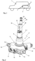
- the tank valve 4 comprises a base body 5, which essentially consists of two sections.
- a first base body section 5.1 is designed in such a way that it protrudes into the respective compressed gas container 3 in the later assembled state of the tank valve 4. In the embodiment shown here, it has a thread designated 6, which is connected to a corresponding thread in a receiving element 7, which in the representation of the Figure 3 is partially indicated, of the pressure gas container 3.
- This first base body section 5.1 also has a Figure 2
- the sealing device indicated consists of one or more sealing rings and/or support rings.
- a second base body section 5.2 is shown in the illustration of the Figure 2 in the lower area of the tank valve 4.
- This second base body section 5.2 is located outside the compressed gas container 3 after the tank valve 4 has been installed, as is shown, for example, in the Figure 3 , in a schematic side view, indicated manner.
- the second base body section 5.2 has several so-called functional subgroups of the tank valve 4.
- the functional subgroups in the second base body section 5.2 comprise an electromagnetically operated pilot valve 9 as a removal valve for removing gas from the compressed gas container 3. It is operated via an electromagnetic coil designated 10, whereby in the illustration of the Figures 2 and 3 only the electromagnetic coil 10 can be seen.
- the pilot valve 9 itself is indicated schematically. Regarding the functionality of such a pilot valve, reference can be made to the explanations in the EN 10 2013 019 978 A1 the applicant should be informed.
- thermally triggered safety valves are known in principle from the general state of the art.
- a screw is used here which has a central hole.
- a solder or a locking body held in place by a solder. If the area of the tank valve 4 or the thermally triggered safety valve 13 heats up beyond the melting temperature of the solder, the through hole in the screw is released and the gas in the interior of the compressed gas container 13 which is in permanent connection with the screw can flow out.
- An alternative to this which is used very frequently in the European and American markets in particular, is a structure in which a valve body is held in position by a glass ampoule containing a slightly boiling liquid.
- the boiling point of the liquid in the glass ampoule is adjusted so that it begins to boil at a critical temperature of the thermally triggered safety valve 13.
- the increase in volume during boiling destroys the glass ampoule and releases the valve body from the valve seat.
- the pressure of the gas in the compressed gas container which is applied to the valve body, moves it into an open position, away from the valve seat, so that the gas can flow out of the compressed gas container 3.
- blow-off line marked 14 which is connected to the interior of the compressed gas container 3 when the thermally triggered safety valve 13 is activated.
- a threaded hole marked 15 in the figures, which is suitable for receiving a screw.
- a so-called blow-off line or venting tube can be easily and reliably installed here. screwed on, for example in the manner described in the German patent application EN 10 2013 015 515 A1 described by the applicant.
- a gas connection 16 can be seen.
- This gas connection can be used, for example, to remove gas from the compressed gas container via the pilot valve 9 and/or to refuel the compressed gas container 3.
- a filter designated 17 is arranged integrated in the gas connection 16, which filter out contaminants in the gas flowing into the compressed gas container 3, in particular when the gas connection 16 is used to refuel the compressed gas container 3.
- a recognizable element in the area of the second base body section 5.2 or in the area of the electromagnetic coil 10 is a plug connection designated 18, via which on the one hand the electromagnetic coil 10 and thus the pilot valve 9 and on the other hand measurement data, for example that of a temperature sensor designated 19, can be transmitted.
- the tank valve 4 has the electrical plug connection 18 as the only electrical connection, so that the wiring of the storage device 2 can be designed accordingly simply and efficiently.
- a slightly curved pipe section 21 can also be seen mounted on it in the direction of the interior of the compressed gas container 3. Its design is selected such that it distributes the inflowing gas into the compressed gas container 3 when the compressed gas container 3 is filled in such a way that the gas is mixed and thus the temperature is reliably measured by the temperature sensor 19.
- An outlet opening 42 of the curved pipe section 21 is ideally narrowed in the flow cross-section compared to the nominal diameter in order to support the formation of a jet of the gas flowing into the compressed gas container 3. This achieves better mixing of the gas with the residual gas inside the compressed gas container, so that a more homogeneous temperature distribution is achieved overall. This benefits the reliable measurement of the temperature by the temperature sensor 19.
- a component designated as 43 is mounted on the first base body section 5.1, which is also referred to below as assembly filter 43.
- This assembly filter comprises a filter 20, as well as a pipe rupture protection device 22 and a check valve 26.
- the pipe rupture protection device 22 and the check valve 26 are some of the functional subgroups which in the embodiment of the Figure 2 are not integrated into the first base body section 5.2, but are mounted on it. The functionality of these two functional subgroups, the pipe rupture protection device 22 and the check valve 26, is described in more detail below using their equally conceivable integrated structure.
- the functional subgroups which are arranged in a protected manner after the tank valve 4 has been installed inside the compressed gas container 3, comprise at least the pipe rupture protection device 22 and a check valve 23 in a refueling line 24, which opens into the pipe section 21.
- a further check valve 26 can be arranged in the extraction path, which has the pipe rupture protection device 22, which ensures that in the event of refueling, the gas flows into the compressed gas container 3 via the refueling line 24 and the pipe section 21, and that in the event of gas being extracted via the pilot valve 9, the flow takes place through the filter 20 and the extraction line 25.
- the check valve 26 is therefore effectively used to select, when the pilot valve 9 is deactivated, whether the gas flows through the refueling line 24 or through the extraction line 25.
- the check valve 26 could therefore also be referred to as a selection valve for the flow path.
- the check valve 26, the pipe rupture protection device 22 and the filter 20 can be integrated as an assembly filter and mounted on the first base body section 5.1 in the direction of the interior of the compressed gas container 3.
- the two valve devices 22, 26 are located in front of the filter 20, so that any particles that may have been rubbed off in the area of the valve devices 22, 26 are retained by the filter 20 and cannot reach the area of the pilot valve 9.
- these components can also be integrated into the base body section 5.1, as shown in the illustration of the Figure 5 is partially indicated.
- a further optional functional subgroup can be seen in the form of a rigid aperture 27 in a line element 28 leading to the thermally triggered safety valve 13, indicated by a dashed line.
- the line element 28 is connected to the interior of the compressed gas container 3 at one end of the first base body section 5.1 without any further valve devices. At its other end, it is connected to the thermally triggered safety valve 13, so that even in the event of a malfunction of another valve device, it is always ensured that the gas flows out of the compressed gas container 3 as desired when the thermally triggered safety valve is activated.
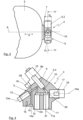
- the alternative representation in Figure 6 shows that in principle the safety valve 13 can also be arranged in the first base body section 5.1 instead of in the second base body section 5.2, for example in the flow direction of the outflowing gas after the orifice 27, as in the illustration of the Figure 6 indicated, or also in the flow direction in front of the orifice 27 if this would be advantageous in terms of the installation space within the first base body section 5.1.
- the safety valve 13 as a functional subgroup can therefore be integrated both in the first base body section 5.1, as shown in the illustration of the Figure 6 can be seen, as well as in the second body section 5.2, as shown in the illustrations of the Figures 2 and 5 is recognizable. In the following, it is therefore mentioned in both construction variants, depending on the design of the respective figure.
- the functional subgroups 13, 22, 23 and, if applicable, 27 and, in addition, the functional subgroup 26 are different from the example according to Figure 2 here arranged in the first base body section 5.1 of the tank valve 4. If damage to the storage device 2 affects individual compressed gas containers 3 and their tank valves 4, this can in particular lead to the tank valve 4 shearing off from the compressed gas container 3. In this case, for example, the second base body section 5.2 would be completely or partially sheared off. Without the compressed gas container 3 itself being damaged, the first functional sub-group 5.1 will typically remain inside the receiving element 7 of the compressed gas container, to which it is screwed.
- the functional sub-groups arranged there 13, 22, 23, 27, 26 are therefore particularly well protected, which is a decisive safety advantage, especially for the safety-relevant functional subgroups 13, 22 and 23.
- the functional subgroups 9, 11, 12, 13, 14, 16, 17 arranged in the second base body section 5.2 as well as the electromagnetic coil 10 corresponding to the pilot valve 9 and cooperating in alignment with it, into which a part of the pilot valve 9 protrudes accordingly, are in terms of their in the representation of the Figure 4 each indicated primary axial orientation, which is indicated by the corresponding axes 9a, 11a, 12a,13a,14a, 16a, in a single plane, namely the one shown in the illustration of the Figure 4 shown section plane IV-IV, which can also be seen from the representation of the Figure 3
- This arrangement of the functional subgroups 9, 11,12, 13, 14, 16, 17 located in the second base body section 5.2 enables an extremely compact arrangement of the entire structure in the axial direction a relative to the axis A, which in the Figures 3 and 5
- the thickness D of the second base body section 5.2 is less than approx.
- the second base body section 5.2 is ideally constructed from an aluminum alloy by forging in one piece with the first base body section 5.1.
- the functional subgroups are then integrated into the base body accordingly.
- the first base body section 5.1 this is done in the representation of the Figure 2 from above, i.e. from the side that will later be inside the pressure gas container 3.
- the other elements are placed in the Figure 4
- the functional sub-assemblies are assembled accordingly in the level shown, for example by screwing the individual functional sub-assemblies as pre-assembled elements into the second base body section 5.2.
- the functional sub-assemblies are typically made from suitable materials, such as stainless steels in particular and, in the area of the sealing seats, possibly also plastics.
- the arrangement in the one level IV-IV which has already been mentioned several times, enables the desired very compact structure to be achieved.
- the representation in the Figure 7 shows again indicated the base body 5 of the tank valve 4 with the first base body section 5.1, which in the assembled state lies inside the compressed gas container and the second base body section 5.2, which typically remains outside the compressed gas container.
- the core of the tank valve 4 is the pilot valve 9 with its electromagnetic coil 10 and a 29 Other functional subgroups include the manual shut-off valve 11, the manual drain valve 12, the thermally triggered safety valve 13, the gas connection 16 and the filter 17.
- the first base section 5.1 contains the pipe rupture protection 22, the check valve 23 in the refueling line 24 and the check valve 26 in the extraction line 25.
- the check valve 26 and the pipe rupture protection device 22 can also be mounted, preferably together with the filter 20, to the first base body section 5.1 on its side facing the interior of the compressed gas container 3 as an assembly filter 43.
- the manual shut-off valve 11 is located between the two and is normally closed, as shown in the illustration of the Figure 7 is open.
- the manual shut-off valve 11 can act accordingly, for example along its axis 11a, on the cross-sectional expansion of the line section 30, for example in that it is designed as a valve seat for a valve body (not shown) of the shut-off valve 11.
- the extraction line 25 and the refueling line 24 also branch off after the manual shut-off valve 11.
- the pipe section 21, the temperature sensor 19 and the filter 20 for the extraction line 25 can also be seen.
- the check valve 26 is located in the extraction line 25, which is connected to the line section 30 via the pilot valve 29, and prevents gas from flowing into the compressed gas tank 3 via the extraction line 25 during refueling.
- the gas would escape from the tank valve 4 via the filter 20 in an area where it would come into very direct contact with the temperature sensor 19.
- the temperature sensor 19, which provides one of the decisive switch-off criteria when refueling the compressed gas tank 3, would then be cooled down unnecessarily, so that in the worst case, refueling would end too early.
- the gas is now extracted in such a way that the check valve 23, supported by the spring indicated, closes.
- the gas then flows into the extraction line 25. It flows via the pipe rupture protection device 22, which is open in the normally state, and the check valve 26, which is open in the extraction case, to the filter 20 and from there to the pilot valve 9.
- the desired amount of gas is achieved by a corresponding electrical control of the electromagnetic coil 10 and via the electrical plug connection 18.
- the desired extraction amount then flows again via the line section 30 and the manual shut-off valve 11, which is open in the normally state, to the gas connection 16 and from there on, for example to a pressure regulator, and then into an internal combustion engine, a fuel cell system, a hot gas turbine or another useful application.
- the manual shut-off valve 11 can be used to manually shut off the tank valve 4. For this purpose, it is separated from its Figure 7 shown open normal position to the other position and thus blocks the line section 30 and thus the extraction path as well as the refueling line 24 by separating it from the gas connection 16. This can be used sensibly, for example, in the context of maintenance, a malfunction or the like.
- the manual drain valve remains connected to the gas connection 16 via the line section 31. It is shown in the illustration of the Figure 7 shown in its normal closed position. At its other end it is connected to the line element 28, which connects the interior of the pressure gas container 3 with the thermally triggered Safety valve 13 - which, as mentioned, could also be arranged in the first base body section 5.1 - and which can have the mentioned rigid aperture 27. If the pressure gas container 3 is now to be emptied, the manual emptying valve can be moved from its Figure 7 shown closed position to the open position. The gas then flows out via the line element 28 and the line element 31 via the gas connection 16.
- thermally triggered safety valve 13 Another conceivable scenario would be the triggering of the thermally triggered safety valve 13. If, for example, a glass ampoule containing a slightly boiling liquid is destroyed in the thermally triggered safety valve 13, then, as already described above, the valve changes from its Figure 7 shown normally closed position to the other open position. The gas can then flow to the blow-off line 14 via the line element 28. In this area, a further line element, a so-called venting tube, is typically connected, which discharges the gas into a non-critical area, particularly in vehicle applications. In this regard, reference can be made to the German application of the applicant mentioned above.
Landscapes
- Engineering & Computer Science (AREA)
- General Engineering & Computer Science (AREA)
- Mechanical Engineering (AREA)
- Filling Or Discharging Of Gas Storage Vessels (AREA)
Description
Die Erfindung betrifft ein Tankventil nach der im Oberbegriff von Anspruch 1 näher definierten Art. Außerdem betrifft die Erfindung die Verwendung eines derartigen Tankventils.The invention relates to a tank valve according to the type defined in the preamble of
Ein Tankventil zur Montage an einem Druckgasbehälter ist aus dem allgemeinen Stand der Technik bekannt. Ein solches Tankventil wird auch häufig mit dem englischen Begriff On-Tank-Valve bzw. seiner Abkürzung OTV bezeichnet. Das Tankventil ist dabei ein Aufbau mit einem Grundkörper, welcher zumindest zwei Abschnitte aufweist, wobei ein erster Grundkörperabschnitt im montierten Zustand in den Druckgasbehälter ragt und dichtend mit diesem verbunden ist. Typischerweise ist dieser erste Grundkörperabschnitt über ein Außengewinde in ein Innengewinde einer korrespondierenden Aufnahme des Druckgasbehälters eingeschraubt. Neben diesem im montiertem Zustand innerhalb des Druckgasbehälters bzw. seines Anschlussgewindes liegenden ersten Grundkörperabschnitt hat der Grundkörper typischerweise einen zweiten Grundkörperabschnitt, welcher sich im montiertem Zustand außerhalb des Druckgasbehälters befindet. Einer oder typischerweise beide der Grundkörperabschnitte weisen nun sogenannte Funktionsuntergruppen auf, welche zur Realisierung der Funktionalität des Tankventils notwendig sind. Derartige Funktionsuntergruppen können beispielsweise ein Entnahmeventil, ein Rückschlagventil in einer Betankungsleitung, ein Sicherheitsventil, ein (manuelles) Absperrventil, ein Filter, eine Anschlussbuchse für eine Betankungs- und/oder Entnahmeleitung oder Ähnliches sein.A tank valve for mounting on a compressed gas container is known from the general state of the art. Such a tank valve is also often referred to by the English term on-tank valve or its abbreviation OTV. The tank valve is a structure with a base body which has at least two sections, with a first base body section protruding into the compressed gas container in the assembled state and being connected to it in a sealing manner. Typically, this first base body section is screwed into an internal thread of a corresponding receptacle of the compressed gas container via an external thread. In addition to this first base body section, which lies inside the compressed gas container or its connection thread when assembled, the base body typically has a second base body section, which is located outside the compressed gas container when assembled. One or typically both of the base body sections now have so-called functional subgroups, which are necessary to implement the functionality of the tank valve. Such functional subgroups can be, for example, a withdrawal valve, a check valve in a refueling line, a safety valve, a (manual) shut-off valve, a filter, a connection socket for a refueling and/or withdrawal line or the like.
Beispielhaft soll hinsichtlich eines derartigen Tankventils auf die
Aus dem Dokument
Druckgasbehälter mit derartigen Tankventilen werden häufig in Kraftfahrzeugen zur Speicherung von gasförmigen Brennstoffen, beispielsweise Erdgas oder Wasserstoff, eingesetzt. Bei Fahrzeuganwendungen spielen dabei immer die Sicherheit und der Crashschutz eine entscheidende Rolle. Bei den herkömmlichen aufgebauten Tankventilen befinden sich zahlreiche Funktionsuntergruppen in dem außerhalb des Druckgasbehälters liegenden zweiten Grundkörperabschnitt, insbesondere da das Bauvolumen für den ersten Grundkörperabschnitt durch den Durchmesser des Gewindes des Druckgasbehälters typischerweise begrenzt ist. Im Falle eines Unfalls mit dem Fahrzeug oder einer andersartigen Beeinträchtigung des Druckgasbehälters durch einen Unfall, was prinzipiell auch außerhalb eines Fahrzeugs auftreten kann, kann es somit zu sicherheitskritischen Situationen kommen, bei welchen sich der Druckgasbehälter unkontrolliert entleeren kann, oder bei welchen er sich aufgrund abgescherter Sicherheitsventile oder dergleichen eben nicht mehr entleeren kann. Kommt es in einer solchen Situation zu einer extremen Wärmeentwicklung, beispielsweise durch einen Brand, dann kann der mit dem beschädigten Tankventil ausgestattete Druckgasbehälter explodieren.Compressed gas containers with such tank valves are often used in motor vehicles to store gaseous fuels, such as natural gas or hydrogen. In vehicle applications, safety and crash protection always play a crucial role. In conventionally constructed tank valves, numerous functional subgroups are located in the second base body section located outside the compressed gas container, particularly since the construction volume for the first base body section is typically limited by the diameter of the thread of the compressed gas container. In the event of an accident with the vehicle or other impairment of the compressed gas container due to an accident, which can in principle also occur outside a vehicle, safety-critical situations can arise in which the compressed gas container can empty uncontrollably, or in which it can no longer empty due to sheared safety valves or the like. If extreme heat develops in such a situation, for example due to a fire, the compressed gas container equipped with the damaged tank valve can explode.
Die Aufgabe der hier vorliegenden Erfindung besteht nun darin, den genannten Nachteil zu vermeiden und einen sicheren Aufbau eines Tankventils anzugeben.The object of the present invention is to avoid the aforementioned disadvantage and to provide a safe construction of a tank valve.
Erfindungsgemäß wird diese Aufgabe durch ein Tankventil mit den Merkmalen im kennzeichnenden Teil des Anspruchs 1 gelöst. Vorteilhafte Ausgestaltungen und Weiterbildungen ergeben sich aus den hiervon abhängigen Unteransprüchen. Im Anspruch 11 ist außerdem eine besonders bevorzugte Verwendung eines derartigen Tankventils angegeben.According to the invention, this object is achieved by a tank valve with the features in the characterizing part of
Das erfindungsgemäße Tankventil weist, ähnlich wie die Tankventile gemäß dem Stand der Technik, einen Grundkörper auf, in welchen mehrere Funktionsuntergruppen zur Betankung des Druckgasbehälters, zur Entnahme von Gas aus dem Druckgasbehälter sowie zur Umsetzung von Sicherheitsfunktionen integriert sind. Ein erster Grundkörperabschnitt ragt dabei in das Innere des Druckgasbehälters und ist insbesondere über ein Gewinde mit einer korrespondierenden Aufnahme in dem Druckgasbehälter, im montierten Zustand dichtend mit diesem verbunden. Erfindungsgemäß ist es nun so, dass einzelne Funktionsuntergruppen in oder an dem ersten Grundkörperabschnitt angeordnet sind. Die Funktionsuntergruppen können dabei insbesondere sicherheitsrelevante Funktionsuntergruppen sein. Durch ihre Anordnung im ersten Grundkörperabschnitt oder in Richtung des Inneren des Druckgasbehälters an diesen montiert sind sie auch im Falle einer Beschädigung des Druckgasbehälters mit dem aufgeschraubten Tankventil vergleichsweise sicher. Dies ist insbesondere dann von Vorteil, wenn der Druckgasbehälter mit dem aufgeschraubten Tankventil beispielsweise in einem Fahrzeug eingesetzt wird, und durch einen Unfall in Mitleidenschaft gezogen wird. Der Druckgasbehälter selbst ist dabei typischerweise sehr stabil, vor allem die Aufnahmeeinrichtung, mit welcher das Tankventil verbunden, in den allermeisten Fällen verschraubt, ist. Der erste Grundkörperabschnitt, welcher innerhalb des Druckgasbehälters und zu einem großen Teil seiner Ausdehnung innerhalb der Aufnahmeeinrichtung des Druckgasbehälters für das Tankventil liegt, ist dementsprechend gut geschützt, sodass selbst bei einer Beschädigung des Tankventils und beispielsweise einem Abscheren des zweiten Grundkörperabschnitts des Tankventils vom ersten Grundkörperabschnitt die in dem ersten Grundkörperabschnitt angeordneten Funktionsuntergruppen unbeschädigt bleiben. Dieser gute Schutz ist insbesondere bei Fahrzeuganwendungen ein entscheidender Vorteil für die Sicherheit.The tank valve according to the invention has, similar to the tank valves according to the prior art, a base body in which several functional subgroups for filling the compressed gas container, for removing gas from the compressed gas container and for implementing safety functions are integrated. A first base body section protrudes into the interior of the compressed gas container and is connected in particular via a thread to a corresponding receptacle in the Compressed gas container, sealed when assembled. According to the invention, individual functional subgroups are arranged in or on the first base body section. The functional subgroups can in particular be safety-relevant functional subgroups. Because they are arranged in the first base body section or mounted on the inside of the compressed gas container, they are comparatively safe even in the event of damage to the compressed gas container with the screwed-on tank valve. This is particularly advantageous if the compressed gas container with the screwed-on tank valve is used in a vehicle, for example, and is damaged in an accident. The compressed gas container itself is typically very stable, especially the mounting device to which the tank valve is connected, in most cases screwed. The first base body section, which lies within the compressed gas container and for a large part of its extent within the receiving device of the compressed gas container for the tank valve, is accordingly well protected, so that even if the tank valve is damaged and, for example, the second base body section of the tank valve is sheared off from the first base body section, the functional sub-groups arranged in the first base body section remain undamaged. This good protection is a decisive advantage for safety, especially in vehicle applications.
Prinzipiell können mehrere der Funktionsuntergruppen in dem ersten Grundkörperabschnitt angeordnet sein. Der dort zur Verfügung stehende Bauraum ist aufgrund der typischerweise beengten Platzverhältnisse im Inneren der Aufnahmeeinrichtung und des notwendigen Materials des ersten Grundkörperabschnitts, um eine ausreichende Stabilität des Tankventils sicherzustellen begrenzt. Daher können in diesem Bereich des ersten Grundkörperabschnitts insbesondere die sicherheitsrelevanten Funktionsuntergruppen angeordnet sein.In principle, several of the functional subgroups can be arranged in the first base body section. The installation space available there is limited due to the typically cramped space conditions inside the receiving device and the material required for the first base body section to ensure sufficient stability of the tank valve. Therefore, the safety-relevant functional subgroups in particular can be arranged in this area of the first base body section.
In dem ersten Grundkörperabschnitt ist zumindest ein Rückschlagventil in dem Betankungspfad oder in einer diesen innerhalb des Grundkörpers ausbildenden Betankungsleitung vorgesehen. Ein solches Rückschlagventil in einer Betankungsleitung stellt sicher, dass die Betankungsleitung, wenn sie nicht verwendet wird, von dem in dem Druckgasspeicher unter Druck stehenden Gas verschlossen wird. Hierfür ist typischerweise ein Rückschlagventil mit einer zusätzlichen Federunterstützung entgegen der Strömungsrichtung bei der Betankung vorgesehen. Dieses sicherheitsrelevante Bauteil kann nun im ersten Grundkörperabschnitt angeordnet sein, sodass es sehr sicher untergebracht ist.In the first base body section, at least one non-return valve is provided in the refueling path or in a refueling line forming this within the base body. Such a non-return valve in a refueling line ensures that the refueling line, when not in use, is closed off by the gas under pressure in the compressed gas storage tank. For this purpose, a non-return valve with additional spring support is typically provided against the flow direction during refueling. This safety-relevant The component can now be arranged in the first base body section so that it is housed very securely.
Ferner ist vorgesehen, dass die Funktionsuntergruppen in dem ersten Grundkörperabschnitt eine Rohrbruchsicherung in dem Entnahmepfad umfassen. Eine solche Rohrbruchsicherung stellt sicher, dass im Falle eines Bruchs oder eines Defekts der Rohrleitung diese verschlossen wird. Sie kann insbesondere aus einer Ventileinrichtung bestehen, welche in Abhängigkeit eines Differenzdrucks zwischen der einen dem Inneren des Druckgasbehälters zugewandten Seite und der anderen der Abströmseite einer Entnahmeleitung zugewandten Seite wirkt. Liegt auf der Seite des Entnahmepfads kein Druck mehr vor oder senkt sich dieser rapide ab, beispielweise weil die Leitung oder ein in der Leitung angeordnetes Ventil beschädigt oder abgeschert wird, dann verschließt die Rohrbruchsicherung mit einem Ventilkörper das Rohr und verhindert so das Abströmen von Gas aus dem Druckgasbehälter. Auch dieses sicherheitsrelevante Bauteil kann nun insbesondere im Inneren des Druckgasbehälters und damit an oder im ersten Grundkörperabschnitt des Tankventils angeordnet sein.It is further provided that the functional subgroups in the first base body section comprise a pipe rupture safety device in the extraction path. Such a pipe rupture safety device ensures that in the event of a rupture or defect in the pipeline, the pipeline is closed. It can in particular consist of a valve device which acts as a function of a differential pressure between the one side facing the interior of the compressed gas container and the other side facing the outflow side of an extraction line. If there is no longer any pressure on the side of the extraction path or if it drops rapidly, for example because the line or a valve arranged in the line is damaged or sheared off, the pipe rupture safety device closes the pipe with a valve body and thus prevents gas from flowing out of the compressed gas container. This safety-relevant component can now also be arranged in particular inside the compressed gas container and thus on or in the first base body section of the tank valve.
Gemäß einer weiteren sehr günstigen Ausgestaltung der Idee kann es ferner vorgesehen sein, dass die Funktionsuntergruppen im ersten Grundkörperabschnitt eine starre Blende in einem zu oder von einem Sicherheitsventil führenden Leitungselement umfassen. Typischerweise weisen Tankventile Sicherheitsventile, beispielsweise thermisch auslösende Sicherheitsventile, auf. Über diese Sicherheitsventile wird, für den Fall, dass diese ansprechen, Gas aus dem Inneren des Druckgasbehälters abgeblasen, um einen extremen Überdruck und die Gefahr einer Explosion des Druckgasbehälters zu vermeiden. Dies kann beispielsweise beim Auftreten von Feuer der Fall sein. Um ein unkontrolliertes Abströmen auch für den Fall, dass das Tankventil selbst beschädigt und beispielsweise das Sicherheitsventil, welches in dem zweiten Grundkörperabschnitt angeordnet sein kann, von dem ersten Grundkörperabschnitt abgetrennt wird, kann gemäß dieser vorteilhaften Weiterbildung der Idee eine starre Blende in dem ersten Grundkörperabschnitt vorgesehen sein. Über diese starre Blende wird konstruktionsbedingt das Volumen des abströmenden Gases begrenzt, sodass das Gas aus dem Inneren des Druckgasbehälters mit einem vergleichsweise kontrollierten Volumenstrom abströmt und nicht unkontrolliert in die Umgebung gelangt.According to another very advantageous embodiment of the idea, it can also be provided that the functional subgroups in the first base body section comprise a rigid aperture in a line element leading to or from a safety valve. Tank valves typically have safety valves, for example thermally triggered safety valves. If these safety valves are activated, gas is released from the interior of the compressed gas container via these safety valves in order to avoid extreme overpressure and the risk of the compressed gas container exploding. This can be the case, for example, if a fire occurs. In order to prevent uncontrolled outflow even if the tank valve itself is damaged and, for example, the safety valve, which can be arranged in the second base body section, is separated from the first base body section, a rigid aperture can be provided in the first base body section according to this advantageous development of the idea. Due to its design, this rigid aperture limits the volume of the escaping gas so that the gas flows out of the interior of the compressed gas container at a comparatively controlled volume flow and does not escape into the environment in an uncontrolled manner.
In einer weiteren, sehr vorteilhaften Variante des erfindungsgemäßen Tankventils kann es nun außerdem vorgesehen sein, dass ein Sicherheitsventil, insbesondere ein thermisch auslösendes Sicherheitsventil, wie im vorherigen Absatz beschrieben, in den ersten Grundkörperabschnitt integriert oder in Richtung des Tankinneren an diesem montiert ist. Für das hinsichtlich der Sicherheit wichtige Sicherheitsventil, insbesondere das wichtige thermisch auslösende Sicherheitsventil, stellt dies einen weiteren Sicherheitsvorteil im Falle einer Beschädigung des Tankventils, beispielsweise durch ein Abscheren des zweiten Grundkörperabschnitts, welcher im montierten Zustand des Tankventils außerhalb des Druckgasspeichers liegt, dar. Da der Grundkörper gemäß einer idealen Ausgestaltung aus einem gut wärmeleitenden metallischen Material wie beispielsweise Aluminium ausgebildet ist, wird im Falle einer erhöhten Temperatur beispielsweise durch einen Brand, die Wärme über den Grundkörper zuverlässig in den Bereich des thermisch auslösenden Sicherheitsventils geleitet, sodass seine Integration in den ersten Grundkörperabschnitt 5.1 Vorteile hinsichtlich der Sicherheit und keine nennenswerte Nachteile hinsichtlich der Auslösung mit sich bringt.In a further, very advantageous variant of the tank valve according to the invention, it can now also be provided that a safety valve, in particular a thermally triggered safety valve, as described in the previous paragraph, is integrated into the first base body section or mounted on it in the direction of the interior of the tank. For the safety valve, which is important in terms of safety, in particular the important thermally triggered safety valve, this represents a further safety advantage in the event of damage to the tank valve, for example due to shearing off of the second base body section, which lies outside the compressed gas reservoir when the tank valve is mounted. Since the base body is made from a metallic material with good heat conductivity, such as aluminum, in the event of an increased temperature, for example due to a fire, the heat is reliably conducted via the base body into the area of the thermally triggered safety valve, so that its integration into the first base body section 5.1 brings advantages in terms of safety and no significant disadvantages in terms of triggering.
Gemäß einer weiteren sehr vorteilhaften Idee der Erfindung kann es nun ferner vorgesehen sein, dass weitere Funktionsuntergruppen in dem zweiten Grundkörperabschnitt angeordnet sind. Dabei kann es vorgesehen sein, dass alle in dem zweiten Grundkörperabschnitt, also dem im montierten Zustand außerhalb des Druckgasbehälters liegenden Abschnitt des Grundkörpers, angeordneten Funktionsuntergruppen in einer Ebene angeordnet sind. Diese Anordnung in einer Ebene bezieht sich dabei auf die primäre axiale Ausrichtung und die Betätigungsrichtung der einzelnen Funktionsuntergruppen. Insbesondere können die Funktionsuntergruppen so ausgestaltet sein, sodass sie mit dem Grundkörper verschraubt werden können. Die Mittelachsen der Bohrungen in dem Grundkörper mit den Gewinden zur Aufnahme derartiger Funktionsuntergruppen sind bei dem erfindungsgemäßen Tankventil dabei in einer einzigen Ebene des Grundkörpers angeordnet. Diese Integration aller Funktionsuntergruppen in dem zweiten Grundkörperabschnitt innerhalb einer einzigen Ebene ermöglicht einen sehr kompakten Aufbau des zweiten Grundkörperabschnitts. Dieser kann beispielsweise beim Einsatz in einem Druckgasbehälter zur Speicherung von Wasserstoff bei einem Nenndruck von 70 MPa so ausgestaltet werden, dass er eine Dicke von lediglich ca. 25 bis 35 mm aufweist. Hierdurch ist ein außerordentlich kompakter Aufbau des erfindungsgemäßen Tankventils möglich.According to another very advantageous idea of the invention, it can now also be provided that further functional subgroups are arranged in the second base body section. It can be provided that all functional subgroups arranged in the second base body section, i.e. the section of the base body that lies outside the compressed gas container in the assembled state, are arranged in one plane. This arrangement in one plane refers to the primary axial alignment and the actuation direction of the individual functional subgroups. In particular, the functional subgroups can be designed so that they can be screwed to the base body. The center axes of the holes in the base body with the threads for receiving such functional subgroups are arranged in a single plane of the base body in the tank valve according to the invention. This integration of all functional subgroups in the second base body section within a single plane enables a very compact structure of the second base body section. For example, when used in a compressed gas container for storing hydrogen at a nominal pressure of 70 MPa, this can be designed so that it has a thickness of only approx. 25 to 35 mm. This enables an extraordinarily compact design of the tank valve according to the invention.
Gemäß einer sehr vorteilhaften Weiterbildung der Idee ist die Ebene dabei senkrecht zu einer zentralen Achse des ersten Grundkörperabschnitts und insbesondere zu einer zentralen Achse des Druckgasbehälters angeordnet. Der erste Grundkörperabschnitt weist typischerweise eine zentrale Achse auf, welche im Allgemeinen mit der zentralen Achse des Druckgasbehälters zusammenfällt, da der erste Grundkörperabschnitt typischerweise mit einer zentralen Aufnahme des Druckgasbehälters verschraubt ist. Zu dieser zentralen Achse, also der Drehachse des Tankventils beim Einschrauben in den Druckgasbehälter, ist die Ebene, welche die Funktionsuntergruppen des zweiten Grundkörperabschnitts aufweist, senkrecht angeordnet. Hierdurch ist ein außerordentlich kompakter Aufbau möglich, bei welchem die axiale Länge des Druckgasbehälters mit montiertem Tankventil außerordentlich klein ist. Insbesondere bei der Verwendung zur Speicherung von Brennstoff in einem Fahrzeug ist dies ein erheblicher Vorteil, da der zur Verfügung stehende Bauraum so in der Art ausgenutzt werden kann, dass das maximale Speichervolumen des Druckgasbehälters realisiert werden kann. Hierdurch lässt sich eine entsprechend große Reichweite des Fahrzeugs erreichen. Insbesondere kann die Reichweite gegenüber der Verwendung von herkömmlichen Tankventilen bei unverändertem in dem Fahrzeug zur Verfügung stehenden Bauraum durch eine Vergrößerung des Volumens des Druckgasbehälters gesteigert werden.According to a very advantageous development of the idea, the plane is arranged perpendicular to a central axis of the first base body section and in particular to a central axis of the compressed gas container. The first base body section typically has a central axis which generally coincides with the central axis of the compressed gas container, since the first base body section is typically screwed to a central receptacle of the compressed gas container. The plane which has the functional subgroups of the second base body section is arranged perpendicular to this central axis, i.e. the axis of rotation of the tank valve when screwed into the compressed gas container. This enables an extremely compact structure in which the axial length of the compressed gas container with the tank valve mounted is extremely small. This is a significant advantage, especially when used to store fuel in a vehicle, since the available installation space can be used in such a way that the maximum storage volume of the compressed gas container can be realized. This allows a correspondingly large range of the vehicle to be achieved. In particular, the range can be increased compared to the use of conventional tank valves without changing the installation space available in the vehicle by increasing the volume of the compressed gas tank.
Gemäß einer sehr günstigen Weiterbildung der Idee sind die Funktionsuntergruppen dabei parallel und/oder sternförmig in dem zweiten Grundkörperabschnitt angeordnet. Innerhalb der Ebene sind die Funktionsuntergruppen also parallel und/oder sternförmig in dem zweiten Grundkörperabschnitt angeordnet. Dies ermöglicht auch hinsichtlich des Bauraums in radialer Richtung, bezogen auf eine zentrale Achse der Ebene, eine sehr kompakte Anordnung. Dies reduziert auch in dieser Richtung den benötigten Bauraum und dient insbesondere auch zur Gewichtseinsparung, da der Grundkörper entsprechend kompakt und mit weniger Material realisiert werden kann. Darüber hinaus erledigt diese Anordnung ein sehr einfaches und effizientes Bohren der Aufnahmen für die Funktionsuntergruppen sowie der in dem zweiten Grundkörperabschnitt verlangenden Kanäle.According to a very advantageous development of the idea, the functional subgroups are arranged in parallel and/or in a star shape in the second base body section. Within the plane, the functional subgroups are therefore arranged in parallel and/or in a star shape in the second base body section. This also enables a very compact arrangement in terms of the installation space in the radial direction, relative to a central axis of the plane. This also reduces the installation space required in this direction and in particular also serves to save weight, since the base body can be made correspondingly compact and with less material. In addition, this arrangement enables very simple and efficient drilling of the receptacles for the functional subgroups and the channels required in the second base body section.
Wie bereits erwähnt können die Funktionsuntergruppen, und so ist es gemäß einer vorteilhaften Weiterbildung des erfindungsgemäßen Tankventils auch vorgesehen, mit dem Grundkörper verschraubt ausgebildet sein.As already mentioned, the functional subgroups can be designed to be screwed to the base body, and this is also provided according to an advantageous development of the tank valve according to the invention.
Eine weitere sehr günstige Ausgestaltung des erfindungsgemäßen Tankventils sieht es nun ferner vor, dass der Grundkörper aus einer Aluminiumlegierung hergestellt ist. Gemäß einer vorteilhaften Weiterbildung kann er insbesondere geschmiedet sein. Eine solche Herstellung des Grundkörpers aus einer Aluminiumlegierung, insbesondere als Schmiedebauteil, ist einfach, kostengünstig, erlaubt die Herstellung eines hochfesten sowie gleichzeitig leichten Bauteils. Die Funktionsuntergruppen können dann typischerweise aus einem nicht rostenden Stahlmaterial ausgebildet verschraubt sein.Another very favorable embodiment of the tank valve according to the invention now also provides that the base body is made of an aluminum alloy. According to an advantageous development, it can in particular be forged. Such production of the base body from an aluminum alloy, in particular as a forged component, is simple, cost-effective and allows the production of a high-strength and at the same time lightweight component. The functional subgroups can then typically be screwed together from a non-rusting steel material.
Gemäß einer weiteren sehr vorteilhaften Ausgestaltung des erfindungsgemäßen Tankventils können dabei in dem zweiten Grundkörperabschnitt zumindest einige der folgenden Funktionsuntergruppen integriert sein:
- Entnahmeventil, insbesondere in Form eines Pilotventils, welches vorzugsweise elektromagnetisch betätigbar ist;
- Sicherheitsventil, insbesondere ein thermisch auslösendes Sicherheitsventil, sofern dieses nicht bereits in den ersten Grundkörperabschnitt angeordnet beziehungsweise an diesem montiert ist;
- ein Absperrventil, vorzugsweise ein manuell betätigbares Absperrventil;
- Entleerventil, insbesondere ein manuell betätigbares Entleerventil;
- Filter, insbesondere Einlassfilter;
- ein Gasanschluss zur Betankung und/oder Entnahme von Gas;
- ein Abblasanschluss, welcher insbesondere mit einem Leitungselement verbindbar ist, welches zur Abfuhr von Gas dient, das über das Sicherheitsventil und/oder das Entleerventil entweicht.
- Extraction valve, in particular in the form of a pilot valve, which is preferably electromagnetically actuated;
- Safety valve, in particular a thermally triggered safety valve, provided that this is not already arranged in the first base body section or mounted on it;
- a shut-off valve, preferably a manually operated shut-off valve;
- Drain valve, in particular a manually operated drain valve;
- Filters, in particular inlet filters;
- a gas connection for refueling and/or withdrawing gas;
- a blow-off connection, which can be connected in particular to a line element which serves to discharge gas escaping via the safety valve and/or the drain valve.
Weitere an sich bekannte Funktionsuntergruppen, welche dem Fachmann grundlegend bekannt sind, können ebenfalls im Bereich des zweiten Grundkörperabschnitts integriert ausgebildet sein.Further functional subgroups known per se, which are fundamentally known to the person skilled in the art, can also be integrated in the region of the second base body section.
Wie bereits mehrfach erwähnt, liegt der entscheidende Vorteil des Tankventils in einer sehr hohen Sicherheit auch für den Fall, dass es zu einer Beschädigung des Tankventils, beispielsweise infolge eines Unfalls, kommt. Dieser Vorteil wirkt sich insbesondere bei Fahrzeuganwendungen entsprechend vorteilhaft aus. Deshalb ist eine Verwendung des Tankventils gemäß Anspruch 10 an einem Druckgasbehälter zur Speicherung von Wasserstoff oder Erdgas, und hier insbesondere bei einem Nenndruck von mehr als 65 MPa, als Brennstoff in einem Fahrzeug vorgesehen.As already mentioned several times, the decisive advantage of the tank valve is its very high level of safety, even in the event that the tank valve is damaged, for example as a result of an accident. This advantage is particularly advantageous in vehicle applications. Therefore, the use of the tank valve according to claim 10 on a compressed gas container for storing hydrogen or natural gas, and here in particular at a nominal pressure of more than 65 MPa, as fuel in a vehicle is provided.
Weitere vorteilhafte Ausgestaltungen des erfindungsgemäßen Tankventils sowie seiner Verwendung ergeben sich außerdem aus den weiteren abhängigen Unteransprüchen sowie aus dem Ausführungsbeispiel, welches nachfolgend unter Bezugnahme auf die Figuren näher beschrieben ist.Further advantageous embodiments of the tank valve according to the invention and its use also emerge from the further dependent subclaims and from the exemplary embodiment which is described in more detail below with reference to the figures.
Dabei zeigen:
- Fig. 1
- ein prinzipmäßig dargestelltes Fahrzeug mit einem Speichersystem für komprimiertes Gas als Brennstoff;
- Fig. 2
- eine dreidimensionale Darstellung einer möglichen Ausführungsform eines Tankventils gemäß der Erfindung;
- Fig. 3
- eine schematische Darstellung eines Teils eines Druckgasbehälters mit montiertem Tankventil;
- Fig. 4
- eine schematische Schnittdarstellung gemäß der Linie IV-IV in
Fig. 3 ; - Fig. 5
- eine schematische Schnittdarstellung durch den im montiertem Zustand in den Druckgasbehälter ragenden Bereich eines Tankventils gemäß der Erfindung; und
- Fig. 6
- eine schematische Schnittdarstellung durch den im montiertem Zustand in den Druckgasbehälter ragenden Bereich eines Tankventils gemäß der Erfindung und gemäß einer alternativen Ausführungsform der Erfindung; und
- Fig. 7
- eine schematische Darstellung der Funktionsweise eines erfindungsgemäßen Tankventils mit allen seinen Funktionsuntergruppen in einem pneumatischen Fließbild.
- Fig.1
- a schematic representation of a vehicle with a storage system for compressed gas as fuel;
- Fig. 2
- a three-dimensional representation of a possible embodiment of a tank valve according to the invention;
- Fig.3
- a schematic representation of part of a compressed gas container with mounted tank valve;
- Fig.4
- a schematic sectional view along the line IV-IV in
Fig.3 ; - Fig.5
- a schematic sectional view through the area of a tank valve according to the invention which projects into the compressed gas container in the assembled state; and
- Fig.6
- a schematic sectional view through the region of a tank valve according to the invention and according to an alternative embodiment of the invention which projects into the compressed gas container in the assembled state; and
- Fig.7
- a schematic representation of the functioning of a tank valve according to the invention with all its functional subgroups in a pneumatic flow diagram.
In der Darstellung der
In der Darstellung der
In der Darstellung der
Als weitere Funktionsuntergruppe in dem zweiten Grundkörperabschnitt 5.2 ist nun außerdem der Teil eines thermisch auslösenden Sicherheitsventils 13 zu erkennen. Solche thermisch auslösenden Sicherheitsventile sind prinzipiell aus dem allgemeinen Stand der Technik bekannt. In einer üblichen Ausführungsform wird hier eine Schraube eingesetzt, welche eine zentrale Bohrung aufweist, In der zentralen Bohrung befindet sich ein Lot oder ein über ein Lot festgehaltener Sperrkörper. Erhitzt sich der Bereich des Tankventils 4 bzw. des thermisch auslösenden Sicherheitsventils 13 über die Schmelztemperatur des Lots hinaus, dann wird die Durchgangsbohrung in der Schraube freigegeben und das mit der Schraube in dauerhafter Verbindung stehende Gas im Inneren des Druckgasbehälters 13 kann abströmen. Eine Alternative hierzu, welche insbesondere im europäischen und amerikanischen Markt sehr häufig eingesetzt wird, besteht in einem Aufbau, bei welchem ein Ventilkörper von einer Glasampulle mit einer leicht siedenden Flüssigkeit in Position gehalten wird. Der Siedepunkt der Flüssigkeit in der Glasampulle ist so abgestimmt, dass diese bei einer kritischen Temperatur des thermisch auslösenden Sicherheitsventils 13 beginnt zu sieden. Durch die Volumenzunahme beim Sieden wird die Glasampulle zerstört und gibt den Ventilkörper gegenüber dem Ventilsitz frei. Durch den Druck des Gases in dem Druckgasbehälter, welcher an dem Ventilkörper ansteht, wird dieser in eine geöffnete Position, weg von dem Ventilsitz, bewegt, sodass das Gas aus dem Druckgasbehälter 3 abströmen kann. Hierfür dient in der Darstellung der
Als weitere Funktionsuntergruppe im Bereich des zweiten Grundkörperabschnitts 5.2 ist in der Darstellung der
Ein weiteres in der Darstellung der
Neben dem Temperatursensor 19 ist im Bereich des ersten Grundkörperabschnitts 5.1 außerdem ein auf diesem in Richtung des Inneren des Druckgasbehälters 3 montierter leicht gebogener Rohrabschnitt 21 zu erkennen. Seine Ausgestaltung ist dabei so gewählt, dass er das einströmende Gas bei der Betankung des Druckgasbehälters 3 möglichst so in den Druckgasbehälter 3 verteilt, dass es zu einer Durchmischung des Gases und damit einer zuverlässigen Messung der Temperatur durch den Temperatursensor 19 kommt. Eine Austrittsöffnung 42 des gebogenen Rohrabschnitts 21 ist dabei idealerweise gegenüber des Nenndurchmessers im Strömungsquerschnitt verengt, um eine Strahlbildung des in den Druckgasbehälter 3 einströmenden Gases zu unterstützen. Damit wird eine bessere Vermischung des Gases mit dem im Inneren des Druckgasbehälters befindlichen Restgas erzielt, sodass insgesamt eine homogenere Temperaturverteilung erreicht wird. Dies kommt der zuverlässigen Messung der Temperatur durch den Temperatursensor 19 zugute.In addition to the
In der
Weitere Funktionsuntergruppen können dabei auch im Inneren des ersten Grundkörperabschnitts 5.1 integriert ausgeführt sein.Further functional subgroups can also be integrated inside the first base body section 5.1.
Die Funktionsuntergruppen, welche nach der Montage des Tankventils 4 im Inneren des Druckgasbehälters 3 entsprechend geschützt angeordnet sind, umfassen dabei zumindest die Rohrbruchsicherung 22 sowie ein Rückschlagventil 23 in einer Betankungsleitung 24, welche in den Rohrabschnitt 21 mündet. Ferner kann in dem Entnahmepfad, welcher die Rohrbruchsicherung 22 aufweist, ein weiteres Rückschlagventil 26 angeordnet sein, welches sicherstellt, dass im Fall einer Betankung das Gas über die Betankungsleitung 24 und den Rohrabschnitt 21 in den Druckgasbehälter 3 einströmt, und dass im Falle einer Entnahme von Gas über das Pilotventil 9 die Strömung durch den Filter 20 und die Entnahmeleitung 25 erfolgt. Über das Rückschlagventil 26 wird also faktisch bei deaktiviertem Pilotventil 9 ausgewählt, ob die Strömung des Gases durch die Betankungsleitung 24 oder durch die Entnahmeleitung 25 erfolgt. Das Rückschlagventil 26 könnte somit auch als Auswahlventil für den Strömungsweg bezeichnet werdenThe functional subgroups, which are arranged in a protected manner after the
Wie bereits erwähnt, können das Rückschlagventil 26, die Rohrbruchsicherung 22 sowie der Filter 20 als Zusammenbaufilter integriert und in Richtung des Inneren des Druckgasbehälters 3 an den ersten Grundkörperabschnitt 5.1. anmontiert werden. In Strömungsrichtung des Gases bei der Entnahme liegen die beiden Ventileinrichtungen 22, 26 dabei vor dem Filter 20, sodass eventuell im Bereich der Ventileinrichtungen 22, 26 abgeriebene Partikel von dem Filter 20 zurückgehalten werden und nicht in den Bereich des Pilotventils 9 gelangen können.As already mentioned, the
Alternativ dazu können diese Bauteile auch in den Grundkörperabschnitt 5.1 integriert ausgeführt werden, wie es in der Darstellung der
In der Darstellung der
Die alternative Darstellung in
Die Funktionsuntergruppen 13, 22, 23 und gegebenenfalls 27 sowie ergänzend die Funktionsuntergruppe 26 sind anders als in dem Beispiel gemäß
Die in dem zweiten Grundkörperabschnitt 5.2 angeordneten Funktionsuntergruppen 9, 11, 12, 13, 14, 16, 17 sowie die mit dem Pilotventil 9 korrespondierende und fluchtend mit ihm zusammenwirkende elektromagnetische Spule 10, in welche ein Teil des Pilotventils 9 entsprechend hineinragt, sind bezüglich ihrer in der Darstellung der
Die Darstellung in der
Die Entnahmeleitung 25, welche in der Darstellung der
Nachfolgend sollen nun die einzelnen Funktionalitäten anhand des in
Bei einer Betankung des Druckgasbehälters 3 strömt Gas über den Gasanschluss 16 und den Filter 17 durch das geöffnete manuelle Absperrventil 11. Der Druck steht dann sowohl in der Betankungsleitung 24 als auch am Pilotventil 9 über dem Leitungsabschnitt 30 an. Ferner steht der Druck am normalerweise geschlossenen manuellen Entleerventil 12 über einen mit 31 bezeichneten Leitungsabschnitt an. Der normale Weg des Gases ist nun der, über die Betankungsleitung 24 durch das Rückschlagventil 23, welches vom Druck des Gases geöffnet wird, und durch den Rohrabschnitt 21 in den Druckgasbehälter. Bei Pilotventilen 9 ist eine sichere Abdichtung bei einer Anströmung in Gegenrichtung nicht bzw. bei höherer Druckdifferenz nicht immer zu gewährleisten. Aus diesem Grund befindet sich in der Entnahmeleitung 25, welche über das Pilotventil 29 mit dem Leitungsabschnitt 30 in Verbindung steht, das Rückschlagventil 26, welches verhindert, dass Gas bei der Betankung über die Entnahmeleitung 25 in den Druckgasbehälter 3 strömt. Dies wäre insbesondere deshalb unerwünscht, da einerseits eine sehr starke Durchströmung des Pilotventils entgegen der geplanten Strömungsrichtung zu einer Beschädigung von Elementen des Pilotventils führen könnte. Außerdem würde das Gas über den Filter 20 in einem Bereich aus dem Tankventil 4 austreten, indem dieses sehr direkt in Kontakt mit dem Temperatursensor 19 käme. Der Temperatursensor 19, welcher eines der entscheidenden Abschaltkriterien bei der Betankung des Druckgasbehälters 3 liefert, würde dann unnötig stark abgekühlt, sodass die Betankung im schlimmsten Fall zu früh beendet werden würde.In the following, the individual functionalities will be explained using the
When the compressed
Im umgekehrten Fall erfolgt die Entnahme von Gas nun so, dass das Rückschlagventil 23, unterstützt durch die angedeutete Feder, sperrt. Das Gas strömt dann in die Entnahmeleitung 25 ein. Es strömt über die im Normalzustand geöffnete Rohrbruchsicherung 22 und das im Entnahmefall geöffnete Rückschlagventil 26 zu dem Filter 20 und von dort zum Pilotventil 9. Die gewünschte Menge an Gas wird durch eine entsprechende elektrische Ansteuerung der elektromagnetischen Spule 10 und über den elektrischen Steckanschluss 18 realisiert. Die gewünschte Entnahmemenge strömt dann wiederum über den Leitungsabschnitt 30 und das im Normalfall geöffnete manuelle Absperrventil 11 zum Gasanschluss 16 und von dort weiter, beispielsweise zu einem Druckregler, und dann in einen Verbrennungsmotor, ein Brennstoffzellensystem, eine Heißgasturbine oder eine sonstige Nutzanwendung.In the opposite case, the gas is now extracted in such a way that the
Über das manuelle Absperrventil 11 kann, wie der Name schon sagt, das Tankventil 4 manuell abgesperrt werden. Hierfür wird es von seiner in
Über den Leitungsabschnitt 31 bleibt das manuelle Entleerventil mit dem Gasanschluss 16 verbunden. Es ist in der Darstellung der
Ein weiteres denkbares Szenario wäre das Auslösen des thermisch auslösenden Sicherheitsventils 13. Wird beispielsweise eine Glasampulle mit leicht siedender Flüssigkeit in dem thermisch auslösenden Sicherheitsventil 13 zerstört, dann wechselt dieses, wie oben bereits beschrieben worden ist, von seiner in
Claims (8)
- A tank valve (4) for installation at a pressure gas tank (3), having a base body (5), comprising a first base body section (5.1), which in the assembled state projects into the pressure gas tank (3) and is sealingly connected with the same, and which comprises a second base body section (5.2), which in the assembled state remains outside of the pressure gas tank (3), further having a plurality of functional sub-groups (9, 11, 12, 13, 14, 16, 17, 22, 23, 26, 27) for refueling the pressure gas tank (3) via a refueling path, for the extraction of gas from the pressure gas tank (3) via an extraction path and for implementing safety and operating functions, wherein at least some of the functional sub-groups (9, 11, 12, 13, 14, 16, 17, 22, 23, 26, 27) at least partially are disposed in the base body (5), whereinin the first base body section (5.1) or on the side facing the interior of the pressure gas tank (3), at the first base body section (5.1) functional sub-groups (13, 22, 23, 26, 27) are disposed,which in or on the first base body section (5.1) comprise a nonreturn valve (23) in the refueling path and which in or on the first base body section (5.1) comprise a pipe burst protection (22) in the extraction path,characterized in that the functional sub-groups (13, 22, 23, 26, 27) comprise in or on the first base body section (5.1) a rigid cover (27) in a line segment (28) leading to or from a safety valve (13).
- The tank valve (4) of Claim 1,
characterized in that
the functional sub-groups (13, 22, 23, 26, 27) comprise in or on the first base body section (5.1) the safety valve, in particular a thermally actuated safety valve (13). - The tank valve (4) of Claim 1,
characterized in that
further functional sub-groups (9, 11, 12, 13, 14, 16, 17) are disposed in the second base body section (5.2), wherein all functional sub-groups (9, 11 ,12, 13, 14, 16, 17) disposed in the second base body section (5.2) are situated in relation to their primary axial alignment (9a, 11a, 12a, 13a, 14a, 16a) and their actuation direction within one plane (IV-IV) in the second base body section (5.2). - The tank valve of Claim 3,
characterized in that
the plane (IV-IV) is situated perpendicular to a central axis (A) of the first base body section (5.1) and, in particular, of the pressure gas tank (3). - The tank valve (4) of Claim 3 or 4,
characterized in that
the functional sub-groups (9, 11, 12, 13, 14, 16, 17) disposed in the second base body section (5.2) comprise at least- an extraction valve, in particular in the form of a pilot valve (9), which preferably is magnetically actuatable;- a safety valve, in particular a thermally actuated safety valve (13);- a shut-off valve, preferably a manually actuatable shut-off valve (11);- a drain valve, in particular a manually actuatable drain valve (12);- a filter (17), in particular an inlet filter;- a gas connection (16) for refueling with gas and / or extracting gas;- a discharge connection (14), which in particular is connectable to a line segment serving to discharge gas, which escapes via the safety valve and / or the drain valve. - The tank valve (4) of any one of Claims 1 to 5,
characterized in that
the base body (5) is manufactured from an aluminum alloy. - The tank valve (4) of any one of Claims 1 to 6,
characterized in that
the base body (5) is formed by forging. - The use of a tank valve (4) of any one of Claims 1 to 6 at a pressure gas tank (3) for storing hydrogen or natural gas as fuel, in particular for a nominal pressure of more than 65 MPa, in a vehicle (1).
Applications Claiming Priority (2)
| Application Number | Priority Date | Filing Date | Title |
|---|---|---|---|
| DE102016008107.4A DE102016008107A1 (en) | 2016-07-01 | 2016-07-01 | tank valve |
| PCT/EP2017/000764 WO2018001560A1 (en) | 2016-07-01 | 2017-06-28 | Tank valve |
Publications (3)
| Publication Number | Publication Date |
|---|---|
| EP3479007A1 EP3479007A1 (en) | 2019-05-08 |
| EP3479007B1 true EP3479007B1 (en) | 2024-07-31 |
| EP3479007C0 EP3479007C0 (en) | 2024-07-31 |
Family
ID=59258173
Family Applications (1)
| Application Number | Title | Priority Date | Filing Date |
|---|---|---|---|
| EP17734241.7A Active EP3479007B1 (en) | 2016-07-01 | 2017-06-28 | Tank valve |
Country Status (6)
| Country | Link |
|---|---|
| US (1) | US10948087B2 (en) |
| EP (1) | EP3479007B1 (en) |
| JP (1) | JP6896777B2 (en) |
| CN (1) | CN109416152B (en) |
| DE (1) | DE102016008107A1 (en) |
| WO (1) | WO2018001560A1 (en) |
Families Citing this family (34)
| Publication number | Priority date | Publication date | Assignee | Title |
|---|---|---|---|---|
| DE102018221600A1 (en) * | 2018-12-13 | 2020-06-18 | Robert Bosch Gmbh | Method for operating a tank device for storing compressed fluids |
| AT16929U1 (en) | 2019-05-28 | 2020-12-15 | Zieger Dipl Ing Andreas | Combination valve |
| CN110630786A (en) * | 2019-09-12 | 2019-12-31 | 江苏国富氢能技术装备有限公司 | Air inlet and outlet structure of high-pressure bottle mouth valve |
| AT16988U1 (en) | 2019-09-27 | 2021-01-15 | Zieger Dipl Ing Andreas | Combination valve |
| CN112918283B (en) * | 2019-12-05 | 2022-04-22 | 未势能源科技有限公司 | A vehicle that is used for gas bomb of vehicle and has it |
| DE102019220512A1 (en) * | 2019-12-23 | 2021-06-24 | Robert Bosch Gmbh | Process for producing a component for storing or distributing compressed gas and a component for storing or distributing compressed gas |
| DE102020200679A1 (en) * | 2020-01-22 | 2021-07-22 | Robert Bosch Gesellschaft mit beschränkter Haftung | Method for opening a valve assembly for a fuel tank |
| DE102020201172A1 (en) * | 2020-01-31 | 2021-08-05 | Robert Bosch Gesellschaft mit beschränkter Haftung | Device for storing compressed gas, vehicle |
| DE102020201170A1 (en) * | 2020-01-31 | 2021-08-05 | Robert Bosch Gesellschaft mit beschränkter Haftung | Valve system and pressure accumulator with one valve system |
| IT202000008932A1 (en) * | 2020-04-24 | 2021-10-24 | Omb Saleri S P A | MULTIFUNCTION VALVE FOR FUEL CELL AUTOTRACTION SYSTEMS |
| JP2021173355A (en) * | 2020-04-27 | 2021-11-01 | 川崎重工業株式会社 | Tank valve device and valve block |
| IT202000009409A1 (en) * | 2020-04-29 | 2021-10-29 | Omb Saleri S P A Soc Benefit | CYLINDER GROUP FOR AN AUTOMOTIVE HYDROGEN FUEL CELL SYSTEM |
| DE102020207253A1 (en) * | 2020-06-10 | 2021-12-16 | Argo Gmbh | Valve device, in-tank valve and gas pressure storage system, in particular for fuel cell systems, as well as methods for detecting a leak |
| DE102020207261A1 (en) * | 2020-06-10 | 2021-12-16 | Argo Gmbh | Thermal pressure relief device (TPRD), gas pressure accumulator and gas pressure accumulator system with TPRD and method for thermal overpressure protection |
| DE102020123037A1 (en) | 2020-09-03 | 2022-03-03 | Bayerische Motoren Werke Aktiengesellschaft | Pressure vessel, pressure vessel system and motor vehicle with fuel rail |
| CN113503467B (en) * | 2021-07-08 | 2023-07-25 | 亚普汽车部件(开封)有限公司 | High-pressure gas cylinder valve for vehicle |
| DE102021207716A1 (en) * | 2021-07-20 | 2023-01-26 | Argo Gmbh | Filling device for hydrogen tanks, hydrogen tank having the filling device and method for filling a hydrogen tank |
| EP4170763A1 (en) * | 2021-10-20 | 2023-04-26 | Robert Bosch GmbH | Discharge and filling system |
| IT202100032546A1 (en) * | 2021-12-23 | 2023-06-23 | Omb Saleri S P A Soc Benefit | CONNECTOR ASSEMBLY FOR A MULTIFUNCTION VALVE OF A FUEL CELL AUTOMOTIVE SYSTEM |
| KR102457115B1 (en) * | 2022-05-13 | 2022-10-20 | 주식회사 네오스펙 | one body type filling and decompressing valve for high pressure tank |
| CN114777017B (en) * | 2022-05-20 | 2024-07-30 | 亚普汽车部件(开封)有限公司 | Vehicular gas bottle valve and production method thereof |
| DE102022208214A1 (en) * | 2022-08-08 | 2024-02-08 | Robert Bosch Gesellschaft mit beschränkter Haftung | Method for filling a fuel gas tank with fuel gas, fuel gas tank and fuel gas tank system |
| DE102022208212A1 (en) * | 2022-08-08 | 2024-02-08 | Robert Bosch Gesellschaft mit beschränkter Haftung | Method for filling a fuel gas tank with fuel gas, fuel gas tank and fuel gas tank system |
| DE102022208213A1 (en) * | 2022-08-08 | 2024-02-08 | Robert Bosch Gesellschaft mit beschränkter Haftung | Method for filling a fuel gas tank with fuel gas, fuel gas tank and fuel gas tank system |
| DE102022208209A1 (en) * | 2022-08-08 | 2024-02-08 | Robert Bosch Gesellschaft mit beschränkter Haftung | Fuel gas tank and fuel gas tank system |
| DE102022208553A1 (en) * | 2022-08-18 | 2024-02-29 | Robert Bosch Gesellschaft mit beschränkter Haftung | Tank system for a hydrogen-powered vehicle, fuel cell assembly, hydrogen internal combustion engine system, fuel cell-powered vehicle, hydrogen-powered vehicle |
| DE102022123005A1 (en) * | 2022-09-09 | 2024-03-14 | Bayerische Motoren Werke Aktiengesellschaft | Valve assembly, pressure vessel system, motor vehicle and manufacturing method for a pressure vessel system |
| DE102022211715A1 (en) * | 2022-11-07 | 2024-05-08 | Robert Bosch Gesellschaft mit beschränkter Haftung | Valve assembly for a fuel gas tank, fuel gas tank with valve assembly |
| DE102022211716A1 (en) * | 2022-11-07 | 2024-05-08 | Robert Bosch Gesellschaft mit beschränkter Haftung | Valve assembly for a fuel gas tank, fuel gas tank with valve assembly |
| DE102022211707A1 (en) * | 2022-11-07 | 2024-05-08 | Robert Bosch Gesellschaft mit beschränkter Haftung | Valve assembly for a fuel gas tank, fuel gas tank with valve assembly |
| DE102022132218A1 (en) * | 2022-12-05 | 2024-06-06 | Bayerische Motoren Werke Aktiengesellschaft | Pressure vessel system with a pressure vessel assembly |
| DE102023202528A1 (en) | 2023-03-21 | 2024-09-26 | Robert Bosch Gesellschaft mit beschränkter Haftung | Valve assembly for a fuel gas tank, fuel gas tank with valve assembly and fuel gas tank system |
| DE102023202526A1 (en) | 2023-03-21 | 2024-09-26 | Robert Bosch Gesellschaft mit beschränkter Haftung | Valve assembly for a fuel gas tank, fuel gas tank with valve assembly and fuel gas tank system |
| DE102023202527A1 (en) | 2023-03-21 | 2024-09-26 | Robert Bosch Gesellschaft mit beschränkter Haftung | Valve assembly for a fuel gas tank, fuel gas tank with valve assembly and fuel gas tank system |
Citations (1)
| Publication number | Priority date | Publication date | Assignee | Title |
|---|---|---|---|---|
| EP2857727A1 (en) * | 2012-06-04 | 2015-04-08 | Youngdo Ind. Co., Ltd. | Fluid control valve assembly |
Family Cites Families (22)
| Publication number | Priority date | Publication date | Assignee | Title |
|---|---|---|---|---|
| US5193580A (en) | 1991-05-30 | 1993-03-16 | Wass Lloyd G | Crash proof solenoid controlled valve with manual override valve |
| DE4334182A1 (en) | 1993-10-07 | 1995-04-13 | Flow Instr & Engineering Gmbh | Shut-off device, especially a valve |
| US5941268A (en) * | 1996-08-29 | 1999-08-24 | Ross, Jr.; Donald P. | Tank safety valve |
| JP2943980B2 (en) * | 1997-07-24 | 1999-08-30 | 本田技研工業株式会社 | Gas fuel piping system |
| DE19852471C2 (en) * | 1998-11-13 | 2003-02-20 | Messer Cutting & Welding Ag | Gas sampling system with interchangeable connection |
| DE10065268C1 (en) * | 2000-12-29 | 2002-08-29 | Novars Ges Fuer Neue Technolog | Pressure vessel with integrated control of a compressed medium |
| US6911065B2 (en) | 2002-12-26 | 2005-06-28 | Matheson Tri-Gas, Inc. | Method and system for supplying high purity fluid |
| DE10361781B4 (en) | 2003-10-21 | 2005-09-15 | Klaus Dipl.-Ing. Perthel | Electromagnetic valve for vehicle gas cylinders has externally threaded casing which screws into cylinder ands has central bore, in which piston and electromagnetic controls are mounted which are fitted through top of bore |
| DE10362052A1 (en) | 2003-10-21 | 2005-09-08 | Klaus Dipl.-Ing. Perthel | Electromagnetic valve for vehicle gas cylinders has externally threaded casing which screws into cylinder ands has central bore, in which piston and electromagnetic controls are mounted which are fitted through top of bore |
| US7152617B1 (en) * | 2004-05-28 | 2006-12-26 | Randal Wade Crawford | High pressure release safety valve assembly |
| CN100458264C (en) * | 2004-08-23 | 2009-02-04 | 丰田自动车株式会社 | High-pressure tank and valve assembly |
| JP4579657B2 (en) | 2004-11-17 | 2010-11-10 | 株式会社ジェイテクト | Valve device fixing structure and manual valve |
| JP4496477B2 (en) * | 2005-03-01 | 2010-07-07 | トヨタ自動車株式会社 | Valve assembly for gas container |
| US20080289700A1 (en) * | 2007-05-24 | 2008-11-27 | Masingale Levi D | High pressure safety valve, system and method |
| JP4984329B2 (en) | 2008-01-16 | 2012-07-25 | トヨタ自動車株式会社 | Valve device and fuel cell system for high pressure tank |
| JP5159360B2 (en) * | 2008-02-19 | 2013-03-06 | 古河スカイ株式会社 | Aluminum alloy for high pressure hydrogen gas and aluminum alloy clad material for high pressure hydrogen gas |
| JP5217625B2 (en) * | 2008-05-22 | 2013-06-19 | 株式会社ジェイテクト | Valve device |
| DE102009046004A1 (en) | 2009-10-26 | 2011-04-28 | Robert Bosch Gmbh | Valve for natural gas tank of motor vehicle, has thermal security device, and piston moving between closing position and opening position |
| CN202972091U (en) * | 2012-11-13 | 2013-06-05 | 杨柳青 | Automatically closed safety valve for heat contact of liquefied gas |
| JP5873451B2 (en) | 2013-02-26 | 2016-03-01 | 川崎重工業株式会社 | Valve device |
| DE102013015515A1 (en) | 2013-09-19 | 2015-03-19 | Daimler Ag | Device for draining gas |
| DE102013019877A1 (en) | 2013-11-26 | 2015-05-28 | Daimler Ag | extraction valve |
-
2016
- 2016-07-01 DE DE102016008107.4A patent/DE102016008107A1/en active Pending
-
2017
- 2017-06-28 EP EP17734241.7A patent/EP3479007B1/en active Active
- 2017-06-28 WO PCT/EP2017/000764 patent/WO2018001560A1/en unknown
- 2017-06-28 US US16/314,049 patent/US10948087B2/en active Active
- 2017-06-28 CN CN201780040735.9A patent/CN109416152B/en active Active
- 2017-06-28 JP JP2018567720A patent/JP6896777B2/en active Active
Patent Citations (1)
| Publication number | Priority date | Publication date | Assignee | Title |
|---|---|---|---|---|
| EP2857727A1 (en) * | 2012-06-04 | 2015-04-08 | Youngdo Ind. Co., Ltd. | Fluid control valve assembly |
Also Published As
| Publication number | Publication date |
|---|---|
| EP3479007A1 (en) | 2019-05-08 |
| US20190170260A1 (en) | 2019-06-06 |
| WO2018001560A1 (en) | 2018-01-04 |
| JP6896777B2 (en) | 2021-06-30 |
| CN109416152B (en) | 2021-11-26 |
| JP2019521296A (en) | 2019-07-25 |
| DE102016008107A1 (en) | 2018-01-04 |
| EP3479007C0 (en) | 2024-07-31 |
| US10948087B2 (en) | 2021-03-16 |
| CN109416152A (en) | 2019-03-01 |
Similar Documents
| Publication | Publication Date | Title |
|---|---|---|
| EP3479007B1 (en) | Tank valve | |
| EP3479008B1 (en) | Tank valve | |
| DE102016008059A1 (en) | tank valve | |
| EP3803191B1 (en) | Tank device for the temperature pressure relief of a fuel cell tank | |
| DE102011114725A1 (en) | Compressed gas tank with a valve device | |
| DE112010000058T5 (en) | Valve system for vehicle high-pressure tank | |
| DE102016008079A1 (en) | tank valve | |
| DE10065268C1 (en) | Pressure vessel with integrated control of a compressed medium | |
| EP1682801A2 (en) | Electromagnetic valve | |
| WO2021151607A1 (en) | Device for storing compressed gas, vehicle | |
| DE102009039079A1 (en) | Tank arrangement for motor vehicle, has compressed gas-operated fuel cell and electric motor, where multiple pressure containers are provided for receiving pressure gas | |
| DE102020108176A1 (en) | Fuel supply system and motor vehicle | |
| DE102014000616A1 (en) | Thermally triggered safety valve | |
| WO2021089294A1 (en) | Tank device for temperature pressure relief in a fuel cell tank | |
| DE202011108934U1 (en) | Device for storing gas under high pressure | |
| WO2015036101A1 (en) | Device for storing gas | |
| DE102006004781B4 (en) | Expansion valve for air conditioning | |
| DE102011114722A1 (en) | Compressed gas tank with a valve | |
| DE102015015004A1 (en) | valve means | |
| WO2017080802A1 (en) | Motor vehicle with a pressure tank and a safety valve device | |
| DE102019120241A1 (en) | Pressure vessel arrangement | |
| EP3236133A1 (en) | Tank system | |
| WO2013045022A2 (en) | Device for storing gas under high pressure | |
| DE102016008106A1 (en) | tank valve | |
| DE102013210335A1 (en) | Galvanic cell and battery system with at least one galvanic cell |
Legal Events
| Date | Code | Title | Description |
|---|---|---|---|
| STAA | Information on the status of an ep patent application or granted ep patent |
Free format text: STATUS: UNKNOWN |
|
| STAA | Information on the status of an ep patent application or granted ep patent |
Free format text: STATUS: THE INTERNATIONAL PUBLICATION HAS BEEN MADE |
|
| PUAI | Public reference made under article 153(3) epc to a published international application that has entered the european phase |
Free format text: ORIGINAL CODE: 0009012 |
|
| STAA | Information on the status of an ep patent application or granted ep patent |
Free format text: STATUS: REQUEST FOR EXAMINATION WAS MADE |
|
| STAA | Information on the status of an ep patent application or granted ep patent |
Free format text: STATUS: REQUEST FOR EXAMINATION WAS MADE |
|
| 17P | Request for examination filed |
Effective date: 20181220 |
|
| AK | Designated contracting states |
Kind code of ref document: A1 Designated state(s): AL AT BE BG CH CY CZ DE DK EE ES FI FR GB GR HR HU IE IS IT LI LT LU LV MC MK MT NL NO PL PT RO RS SE SI SK SM TR |
|
| AX | Request for extension of the european patent |
Extension state: BA ME |
|
| DAV | Request for validation of the european patent (deleted) | ||
| DAX | Request for extension of the european patent (deleted) | ||
| RAP1 | Party data changed (applicant data changed or rights of an application transferred) |
Owner name: DAIMLER AG |
|
| RAP1 | Party data changed (applicant data changed or rights of an application transferred) |
Owner name: 2O CELLCENTRIC GMBH & CO. KG |
|
| RAP3 | Party data changed (applicant data changed or rights of an application transferred) |
Owner name: CELLCENTRIC GMBH & CO. KG |
|
| STAA | Information on the status of an ep patent application or granted ep patent |
Free format text: STATUS: EXAMINATION IS IN PROGRESS |
|
| STAA | Information on the status of an ep patent application or granted ep patent |
Free format text: STATUS: EXAMINATION IS IN PROGRESS |
|
| 17Q | First examination report despatched |
Effective date: 20211105 |
|
| GRAP | Despatch of communication of intention to grant a patent |
Free format text: ORIGINAL CODE: EPIDOSNIGR1 |
|
| STAA | Information on the status of an ep patent application or granted ep patent |
Free format text: STATUS: GRANT OF PATENT IS INTENDED |
|
| INTG | Intention to grant announced |
Effective date: 20240223 |
|
| INTG | Intention to grant announced |
Effective date: 20240223 |
|
| GRAS | Grant fee paid |
Free format text: ORIGINAL CODE: EPIDOSNIGR3 |
|
| GRAA | (expected) grant |
Free format text: ORIGINAL CODE: 0009210 |
|
| STAA | Information on the status of an ep patent application or granted ep patent |
Free format text: STATUS: THE PATENT HAS BEEN GRANTED |
|
| AK | Designated contracting states |
Kind code of ref document: B1 Designated state(s): AL AT BE BG CH CY CZ DE DK EE ES FI FR GB GR HR HU IE IS IT LI LT LU LV MC MK MT NL NO PL PT RO RS SE SI SK SM TR |
|
| REG | Reference to a national code |
Ref country code: CH Ref legal event code: EP Ref country code: GB Ref legal event code: FG4D Free format text: NOT ENGLISH |
|
| REG | Reference to a national code |
Ref country code: DE Ref legal event code: R096 Ref document number: 502017016308 Country of ref document: DE |
|
| REG | Reference to a national code |
Ref country code: IE Ref legal event code: FG4D Free format text: LANGUAGE OF EP DOCUMENT: GERMAN |
|
| U01 | Request for unitary effect filed |
Effective date: 20240731 |