EP3478619B1 - Aufzuganlage, insbesondere in form eines kletterliftsystems, mit speziell ausgebildetem schutzdach - Google Patents
Aufzuganlage, insbesondere in form eines kletterliftsystems, mit speziell ausgebildetem schutzdach Download PDFInfo
- Publication number
- EP3478619B1 EP3478619B1 EP17732927.3A EP17732927A EP3478619B1 EP 3478619 B1 EP3478619 B1 EP 3478619B1 EP 17732927 A EP17732927 A EP 17732927A EP 3478619 B1 EP3478619 B1 EP 3478619B1
- Authority
- EP
- European Patent Office
- Prior art keywords
- cover
- elevator system
- elevator
- lifting platform
- opening
- Prior art date
- Legal status (The legal status is an assumption and is not a legal conclusion. Google has not performed a legal analysis and makes no representation as to the accuracy of the status listed.)
- Active
Links
- 230000001681 protective effect Effects 0.000 title claims description 45
- 230000009194 climbing Effects 0.000 title description 6
- 238000010276 construction Methods 0.000 claims description 32
- 239000000725 suspension Substances 0.000 claims description 18
- 230000002093 peripheral effect Effects 0.000 claims description 9
- 238000009434 installation Methods 0.000 description 13
- 239000002184 metal Substances 0.000 description 7
- 239000002131 composite material Substances 0.000 description 4
- 239000000463 material Substances 0.000 description 4
- 238000004519 manufacturing process Methods 0.000 description 2
- XLYOFNOQVPJJNP-UHFFFAOYSA-N water Substances O XLYOFNOQVPJJNP-UHFFFAOYSA-N 0.000 description 2
- 239000002023 wood Substances 0.000 description 2
- 230000000712 assembly Effects 0.000 description 1
- 238000000429 assembly Methods 0.000 description 1
- 230000001419 dependent effect Effects 0.000 description 1
- -1 for example Substances 0.000 description 1
- 238000012423 maintenance Methods 0.000 description 1
- 239000002905 metal composite material Substances 0.000 description 1
- 238000000034 method Methods 0.000 description 1
- 239000013589 supplement Substances 0.000 description 1
Images


Classifications
-
- B—PERFORMING OPERATIONS; TRANSPORTING
- B66—HOISTING; LIFTING; HAULING
- B66B—ELEVATORS; ESCALATORS OR MOVING WALKWAYS
- B66B11/00—Main component parts of lifts in, or associated with, buildings or other structures
- B66B11/0005—Constructional features of hoistways
-
- B—PERFORMING OPERATIONS; TRANSPORTING
- B66—HOISTING; LIFTING; HAULING
- B66B—ELEVATORS; ESCALATORS OR MOVING WALKWAYS
- B66B11/00—Main component parts of lifts in, or associated with, buildings or other structures
- B66B11/0035—Arrangement of driving gear, e.g. location or support
-
- B—PERFORMING OPERATIONS; TRANSPORTING
- B66—HOISTING; LIFTING; HAULING
- B66B—ELEVATORS; ESCALATORS OR MOVING WALKWAYS
- B66B7/00—Other common features of elevators
- B66B7/02—Guideways; Guides
- B66B7/023—Mounting means therefor
-
- B—PERFORMING OPERATIONS; TRANSPORTING
- B66—HOISTING; LIFTING; HAULING
- B66B—ELEVATORS; ESCALATORS OR MOVING WALKWAYS
- B66B9/00—Kinds or types of lifts in, or associated with, buildings or other structures
Definitions
- the present invention relates to an elevator installation, in particular in the form of a climbing lift system, with a specially designed protective roof.
- Elevator systems are generally used to be able to move people or objects in a usually vertical direction within existing buildings.
- an elevator car can be relocated within an elevator shaft with the help of a suspension element such as one or more ropes or belts.
- the elevator system Before the elevator system is operated in its normal mode of operation, it can possibly already be installed in the building during a construction phase during which a building is not yet completed. It is then possible for the elevator system to be used during the construction phase to transport people and / or material, and for it to grow with the building. In this way, during the construction phase, for example, separate external elevators that would have to be attached to the outside of the building, for example, can be dispensed with.
- a part of guide rails and an elevator car can be installed in the elevator shaft provided for the elevator system at a point in time at which one or more lower floors of the building have only been completed.
- the elevator car and other components of the elevator system can typically be suspended from a lifting platform by means of the support means.
- a drive machine can be provided on the lifting platform, which can move the support means, for example with the aid of a traction sheave.
- the lifting platform can be raised to a next higher level, for example with a crane or other means, in order to lengthen the transport path of the elevator system.
- the guide rails and / or the holding rails of the elevator system provided for guiding the lifting platform can be successively attached to the elevator shaft during the construction phase of the building
- Lifting platform can be transported upwards on the guide rails or retaining rails if necessary.
- the lifting platform can then be fixed at a desired higher position, for example with struts, which can be pushed out of the lifting platform into openings in the walls of the elevator shaft, for example.
- WO 2015/003964 A1 shows an example of a climbing lift system.
- FR3007008 shows a method for installing a drive for an elevator system.
- the invention relates to an elevator installation with a lifting platform and a protective roof for the lifting platform.
- An elevator installation can comprise an elevator cage and a suspension element, the elevator cage being held by the suspension element and being displaceable within the elevator shaft along at least one guide rail by means of the suspension element.
- the support means can be held on the lifting platform.
- the protective roof can be arranged above components of the lifting platform to be protected, such as a drive machine. People and / or objects can be transported with the elevator car.
- the lifting platform can be designed for fastening at several fastening positions in the elevator shaft.
- the lifting platform can, on the one hand, be designed to hold the weight of the elevator car and, if necessary, a counterweight that is also attached to the suspension element with the aid of the suspension element held on it.
- the suspension means should be held on the lifting platform in such a way that they can be displaced and thus the elevator car held on the suspension means can also be displaced.
- a drive machine which serves to drive the suspension element, can optionally be arranged on the lifting platform.
- the drive machine can, for example, drive a drive pulley in rotation and the suspension element can be placed around the drive pulley in order to be able to be displaced by the latter.
- only deflection rollers can be provided on the lifting platform, around which the suspension element is wound, and a drive machine can be arranged at a different position within the elevator shaft or within a machine room in order to be able to move the suspension element.
- Other configurations can also be used in which the support means is held fixedly on the lifting platform or can be displaced relative to it.
- the lifting platform can furthermore have a protective roof which is designed to protect the lifting platform from falling objects.
- the protective roof can be attached over the lifting platform and / or on the lifting platform.
- the protective roof is provided, inter alia, to protect components of the lifting platform located below the protective roof, in particular from falling objects coming from above and possibly also dirt or water. People located in the elevator shaft below the protective roof may also need to be protected.
- the elevator system with its lifting platform is designed to be temporarily attached to different positions within the elevator shaft, i.e. when the elevator system is designed as a climbing lift system to be used in a building during a construction phase and / or can grow with the building during this construction phase by gradually moving the lifting platform.
- the elevator shaft in the building is typically still open to the top.
- the lifting platform is typically not arranged at a highest point of the building or at least the elevator shaft, as is the case with completed buildings usually the case.
- the elevator system has at least one guide rail for vertically guiding the elevator car in the elevator shaft, the protective roof having a rail opening through which the guide rail runs and the protective roof having a cover for covering the rail opening which has a cover opening, through which the guide rail runs.
- the elevator car is guided by several guide rails in the elevator shaft. These guide rails are usually attached to the side walls of the elevator shaft and / or can also be installed above the lifting platform.
- the lifting platform If the lifting platform is repositioned in the elevator shaft, the lifting platform must be moved along the guide rails, for this purpose the rail openings are available, which can also be designed so that components fastened to the guide rails, such as rail clips for fastening the guide rails, through the lifting platform and in particular the canopy can be moved through.
- the rail openings are available, which can also be designed so that components fastened to the guide rails, such as rail clips for fastening the guide rails, through the lifting platform and in particular the canopy can be moved through.
- the rail openings can each be covered with a cover when the lifting platform has reached its next fastening position and / or the elevator system is put into operation.
- the cover can cover the rail opening except for a gap between the guide rail and an edge of the cover opening. It can thus be avoided that objects can fall down through the rail opening.
- the cover opening has a shape that corresponds to a cross section of the guide rail.
- a gap between an edge of the cover opening and the guide rail can be essentially the same width.
- the cover opening and a cross section of the guide rail are T-shaped.
- Guide rails often have a T-profile.
- the lid opening can also be T-shaped.
- the cover opening is shaped in such a way that a gap with a maximum width of 30 mm, for example a maximum of 10 mm, is present between the cover and the guide rail.
- the cover is formed from at least two cover parts.
- the two cover parts can be placed on the side of the guide rail in order to form the cover opening.
- the two cover parts can touch or overlap along one edge.
- the cover opening is provided by only one cover part. It is possible that one cover part is essentially rectangular, while the other cover part has a recess on one edge which can have a shape corresponding to the guide rail.
- the lid opening is provided by two of the lid parts. It is also possible for two cover parts to have recesses on opposite edges, which together can have a shape corresponding to the guide rail.
- a cross section of the rail clamp is arranged completely within the cross section of the rail opening, the guide rail being attachable to a side wall of the elevator shaft by means of the rail clamp.
- the lifting platform with the protective roof can be moved past the rail clamp without collisions between the rail clamp and the central roof structure when the cover is opened over the rail opening.
- the guide rail can be extended beyond the lifting platform before the lifting platform is moved.
- the cover is fastened to the protective roof by means of hinges.
- the cover is only placed on the rail opening. If the cover and in particular the cover parts are fastened to the protective roof by means of hinges, a closed position of the cover can be defined in this way and / or the cover and / or the cover parts cannot be lost.
- the cover is arranged on an edge of the protective roof.
- the cover or cover parts of the cover can be pivotable upwards about a hinge axis parallel to the edge and / or orthogonally to the edge. It is possible for a cover part to be pivoted or displaced towards a side wall and / or another cover part on which the cover or the rail opening is arranged, away from the side wall. Alternatively, the two cover parts can be pivoted or shifted about an axis essentially orthogonally to the sides.
- the cover is placed on a cover box which is attached to the protective roof.
- the cover box can, for example, have a plurality of side walls which are attached to the protective roof at their lower edge and the cover is placed on the upper edge thereof. If the cover is fastened to the protective roof via hinges, these hinges can be fastened to the cover box and in particular to its side walls.
- the cover box extends up to an edge of the protective roof. It is possible that an edge of the lid box provides an edge of the protective roof.
- the protective roof comprises a horizontally extending, central roof structure.
- the cover can be arranged at least partially over the central roof structure.
- the central roof structure can be arranged above central areas of the lifting platform and cover them.
- the central roof structure can be designed and dimensioned in such a way that it does not, for example needs to be dismantled if the lifting platform is to be relocated within the elevator shaft.
- the central roof structure can be dimensioned in such a way that its edges are sufficiently spaced from the side walls of the elevator shaft, that is to say, for example, by at least 10 cm, preferably by at least 30 cm.
- the central roof structure can, for example, be a plate made of a sufficiently stable material, for example a metal plate. It can also be composed of several plates.
- the central roof structure can have a rail opening for each guide rail, through which the guide rail runs.
- the cover box which carries the cover for covering the rail opening, can be arranged around this rail opening.
- the protective roof has a peripheral flank construction that runs obliquely to a horizontal.
- This flank construction can have flank walls which protrude obliquely upwards from the central roof construction.
- the cover can be arranged at least partially over the peripheral flank construction or between sub-elements of a flank wall of the flank construction.
- peripheral flank construction Adjacent to the lateral edges of the central roof structure, areas with a peripheral flank structure can be connected in each case.
- the peripheral flank construction is thus predominantly arranged in areas between the central roof construction and the surrounding side walls of the elevator shaft.
- flank construction of the protective roof can have flank walls which are attached to the lateral edges of the central roof construction. These flank walls protrude outwards from the central roof structure, that is to say towards a respective adjacent wall of the elevator shaft. In this case, however, the flank walls are not aligned horizontally, but rather extend at an angle inclined to the horizontal.
- the inclined flank walls can form a funnel so that objects falling from above onto the flank walls are deflected towards the central roof structure and can be caught there.
- flank walls and / or the lid box can be attached to the central roof structure in a position and orientation in which the edge areas or edges of the flank walls and / or the lid box are less than 30 mm, preferably less than 10 mm, from the side walls of the elevator shaft .
- flank construction and optionally the cover boxes can be detached from the central roof construction when the lifting platform is to be moved in the elevator shaft.
- the lid box on which the lid is placed is attached to the central roof structure.
- the peripheral flank construction which runs obliquely to a horizontal, can be attached to the side of the cover box. This means that the cover box can also extend to the edge of the protective roof. In this way, the cover box can interrupt or supplement the flank construction in the area of a guide rail.
- the cover, the cover box, its side walls and / or the flank walls are made of metal or a composite material provided with a metal layer. It is true that these components can consist of any sufficiently mechanically stable material such as, for example, plastic, plastic composite materials, wood, wood composite materials or the like. However, it is considered to be advantageous to make these components from metal or at least with a metal layer, since on the one hand sufficient mechanical strength and on the other hand simple manufacture can be achieved with low manufacturing and material costs.
- Fig. 1 shows an elevator installation 1 in the form of a climbing lift system.
- the elevator installation 1 comprises an elevator shaft 3 in which an elevator car 5 and a counterweight 7 are accommodated.
- the elevator car 5 and the counterweight 7 are held on a lifting platform 11 with the aid of a suspension element 9.
- the suspension element 9 typically comprises several ropes or belts.
- the elevator installation 1 further comprises guide rails 12 on which the elevator car 5 is guided vertically in the elevator shaft.
- the lifting platform 11 is at least temporarily firmly attached in the elevator shaft 3. Fastening points 13 are attached to the lifting platform 11, at which ends of the support means 9 are firmly held. Furthermore, a drive machine 15 is provided on the lifting platform 11. This drive machine 15 drives a traction sheave 17 in a rotating manner. The support means 9 is wound around the traction sheave 17 and can thus be displaced by the rotating traction sheave 17, whereby the elevator car 5 can be guided on the guide rails 12 and the counterweight 7 can be moved in opposite directions within the elevator shaft 3.
- the elevator system 1 is designed to be used in a building during a construction phase. This means that the elevator installation 1 can already be operated when the building that houses it is only partially completed. After certain construction progresses, the lifting platform 11 can be shifted upwards within the elevator shaft 3 and thus the elevator installation 1 "grows" with the building. In order to move the lifting platform 11, anchors 19 (only shown very schematically) can be temporarily released, then the lifting platform 11 can be raised, for example by means of a crane, and if necessary the support means 9 can be suitably extended and finally the lifting platform 11 at its new fastening position again in the elevator shaft 3 to be anchored.
- a protective roof 21 is provided above such components to be protected, which is intended to act as a crash deck.
- the protective roof 21 is supported by supports 31 on a support plate 33 of the lifting platform 11 and spans large parts of the cross-sectional area of the elevator shaft 3 above the components to be protected designed in such a way that it has sufficient stability to be able to protect the underlying components to be protected against objects falling from above, such as typically screws, tools, small stones, etc.
- the protective roof 21 has a central roof structure 23.
- the central roof structure 23 is preferably flat and can consist of one or more composite panels, for example metal panels or metal composite panels or wooden panels of sufficient thickness.
- flank construction 25 Adjacent to the lateral edges 30 of the roof structure 23, a flank structure 25 is provided.
- the flank construction 25 has flank walls 27 which are fastened in their lower end regions 28 to the lateral edges 30 of the roof construction 23 and which are inclined from there to the horizontal 29 (see FIG Fig. 1 ) protrude diagonally upwards outwards. At their upper end regions, the flank walls 27 form an outer edge 35 of the protective roof 21.
- flank walls 27 are arranged at an angle ⁇ of typically between 40 ° and 50 ° to the horizontal 29.
- the flank walls 27 extend up to or at least just in front of an adjacent side wall 4 of the elevator shaft 3 and thus close a gap that would otherwise open between the central roof structure 23 and the side wall 4.
- Each or at least some of the guide rails 12 run through a rail opening 37 in the support plate 33 of the lifting platform 11 and through a rail opening 39 in the central roof structure 23.
- the rail opening 39 is closed by a cover 41, which in turn has a cover opening 43, which is significantly smaller than the rail opening 39.
- the cover 41 thus protects the components of the elevator installation 1 lying under the protective roof 21 from falling objects, since the rail opening 39 is almost completely closed by the cover 41.
- the lid 41 can be made from one or more substantially flat metal plates.
- the rail openings 37, 39 have a width such that a rail clip 45, with which the associated guide rail 12 is attached to a wall 4 of the elevator installation 1, can be passed through them when the lifting platform 11 is moved. In order to move the lifting platform 11, it is therefore only necessary to remove the cover 41, which is attached to the rail opening 39, for example.
- a cover box 47 which can have a plurality of vertical side walls 49 and which surrounds the rail openings 39, can be attached to the protective roof 21 or the central roof structure 23.
- the cover 41 can also be designed as a cover for the cover box 47 and / or be placed on its upper end.
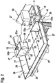
- the Fig. 2 shows perspective views of several lid boxes 47 and several lids 41.
- Each of the lid boxes 47 extends up to the edge 35 of the protective roof 21, the side of the lid box 47 facing the associated wall 4 being open. Furthermore, each of the lid boxes 47 is attached to the horizontally extending, central roof structure 23.
- the peripheral flank construction 25, which runs obliquely to the horizontal, is fastened laterally via the flank walls 27 to the respective cover box 47.
- the guide rails 12 have a T-shaped cross section.
- a corresponding shape of the cover openings 43 is also T-shaped.
- Each of the cover openings 43 is shaped in such a way that only a narrow gap remains between the respective guide rail 12 and the edge of the cover openings 43, which for example has a maximum width of less than 30 mm, such as approximately 10 mm. It is possible for one lid to have several Has cover openings 43, or that several guide rails 12 run through a rail opening 37, 39.
- a cover 41 can be divided into two or more cover parts 53a, 53b, between which (apart from the cover openings 43) only a slot (for example narrower than 10 mm) is formed when the cover 41 is located on the rail opening 39.
- these cover parts 53a, 53b can overlap.
- cover opening 43 or one cover opening 43 is formed completely within a cover part 53, the other cover part 53b merely providing an edge of the cover opening 43.
- the cover opening 43 is formed by two cover parts 53a, 53b.
- each of the cover parts 53a, 53b can be connected to the cover box 47 via a hinge 55.
- the hinges 55 are arranged in such a way that the hinge axis 57 runs essentially orthogonally to the wall 4 or the edge 35 of the protective roof 21, next to which the cover 41 is arranged.
- the slot 59 separating the cover parts 53a, 53b also runs essentially orthogonally to the wall 4 or the edge 35 of the protective roof 21.
- the cover parts 53a, 53b can thus be folded outwards along the wall 4 or the edge 35, as through the arrows are indicated.
- the rail clip 45 protrudes from the wall 4 and clasps a base of the guide rail 12.
- the rail opening 39 which is formed as a rectangular opening in the central roof structure 23, is located on the edge of the central roof structure 23.
Description
- Die vorliegende Erfindung betrifft eine Aufzuganlage, insbesondere in Form eines Kletterliftsystems, mit einem speziell ausgebildeten Schutzdach.
- Aufzuganlagen werden im Allgemeinen dazu eingesetzt, innerhalb bestehender Gebäude Personen bzw. Gegenstände in einer üblicherweise vertikalen Richtung befördern zu können. Hierzu kann eine Aufzugkabine mithilfe eines Tragmittels wie z.B. eines oder mehrerer Seile oder Riemen innerhalb eines Aufzugschachts verlagert werden.
- Bevor die Aufzuganlage in ihrer normalen Betriebsweise betrieben wird, kann sie eventuell bereits während einer Bauphase, während der ein Gebäude noch nicht fertiggestellt ist, in dem Gebäude installiert werden. Es ist dann möglich, dass die Aufzuganlage während der Bauphase bereits zum Transport von Personen und/oder Material verwendet wird, und dass sie während des Baus des Gebäudes mitwächst. Auf diese Weise kann während der Bauphase zum Beispiel auf gesonderte externe Aufzüge, die beispielsweise an einer Außenseite des Gebäudes anzubringen wären, verzichtet werden.
- Dazu kann beispielsweise ein Teil von Führungsschienen und eine Aufzugkabine in dem für die Aufzuganlage vorgesehenen Aufzugschacht bereits zu einem Zeitpunkt montiert werden, zu dem erst ein oder mehrere untere Stockwerke des Gebäudes fertiggestellt wurden. Die Aufzugkabine und weitere Komponenten des Aufzugsystems wie z.B. ein Gegengewicht können dabei typischerweise mittels der Tragmittel an eine Hebeplattform gehängt sein. An der Hebeplattform kann eine Antriebsmaschine vorgesehen sein, welche die Tragmittel beispielsweise mithilfe einer Treibscheibe verlagern kann. Die Hebeplattform kann beispielsweise mit einem Kran oder anderen Mitteln auf eine nächsthöhere Ebene angehoben werden, um den Transportweg der Aufzuganlage zu verlängern.
- Beispielsweise können bei einem Kletterliftsystem die Führungsschienen und/oder zur Führung der Hebeplattform vorgesehene Halteschienen des Aufzugsystems sukzessive während der Bauphase des Gebäudes im Aufzugschacht angebracht werden und die Hebeplattform bei Bedarf an den Führungsschienen bzw. Halteschienen nach oben befördert werden. Die Hebeplattform kann dann an einer gewünschten höheren Position beispielsweise mit Streben fixiert werden, die z.B. aus der Hebeplattform heraus in Öffnungen in den Wänden des Aufzugschachts geschoben werden können.
- Die
WO 2015/003964 A1 zeigt ein Beispiel eines Kletterliftsystems.FR3007008 - Insbesondere für eine während der Bauphase eines Gebäudes eingesetzte Aufzuganlage kann eine Gefahr bestehen, dass Komponenten der Aufzuganlage durch Schmutz oder herabfallende Gegenstände geschädigt werden. Auch sich innerhalb des Aufzugschachts befindliche Personen wie beispielsweise Wartungspersonal könnten z.B. durch herabfallende Gegenstände zu Schaden kommen.
- Es kann daher unter anderem ein Bedarf an einer Aufzuganlage bestehen, bei der Komponenten der Aufzuganlage und/oder im Aufzugschacht befindliche Personen effizient gegen herabfallende Gegenstände oder Schmutz geschützt sind.
- Einem solchen Bedarf kann durch den Gegenstand des unabhängigen Anspruchs entsprochen werden. Vorteilhafte Ausführungsformen sind in den abhängigen Ansprüchen sowie der nachfolgenden Beschreibung definiert.
- Mögliche Merkmale und Vorteile von Ausführungsformen der Erfindung können unter anderem und ohne die Erfindung einzuschränken als auf nachfolgend beschriebenen Ideen und Erkenntnissen beruhend angesehen werden.
- Die Erfindung betrifft eine Aufzuganlage mit einer Hebeplattform und einem Schutzdach für die Hebeplattform. Eine Aufzuganlage kann eine Aufzugkabine und ein Tragmittel umfassen, wobei die Aufzugkabine von dem Tragmittel gehalten ist und mittels des Tragmittels innerhalb des Aufzugschachts entlang wenigstens einer Führungsschiene verlagerbar ist. Das Tragmittel kann an der Hebeplattform gehalten sein. Weiter kann das Schutzdach oberhalb zu schützender Komponenten der Hebeplattform, wie etwa einer Antriebsmaschine, angeordnet sein. Mit der Aufzugkabine können Personen und/oder Gegenstände befördert werden.
- Die Hebeplattform kann zum Befestigen an mehreren Befestigungspositionen in dem Aufzugschacht ausgeführt sein. Die Hebeplattform kann einerseits dazu ausgelegt sein, mithilfe des an ihr gehaltenen Tragmittels das Gewicht der Aufzugkabine sowie gegebenenfalls eines ebenfalls an dem Tragmittel befestigten Gegengewichts zu halten. Andererseits sollten die Tragmittel derart an der Hebeplattform gehalten werden, dass diese verlagert werden können und somit die an dem Tragmittel gehaltene Aufzugkabine ebenfalls verlagert werden kann. An der Hebeplattform kann hierzu gegebenenfalls eine Antriebsmaschine angeordnet sein, welche zum Antreiben des Tragmittels dient. Die Antriebsmaschine kann beispielsweise eine Treibscheibe rotierend antreiben und das Tragmittel kann um die Treibscheibe gelegt sein, um von dieser verlagert werden zu können. Alternativ können an der Hebeplattform lediglich Umlenkrollen vorgesehen sein, um die das Tragmittel gewunden ist, und eine Antriebsmaschine kann an einer anderen Position innerhalb des Aufzugschachts oder innerhalb eines Maschinenraums angeordnet sein, um das Tragmittel verlagern zu können. Auch andere Konfigurationen, in denen das Tragmittel an der Hebeplattform fest oder relativ zu dieser verlagerbar gehalten ist, können eingesetzt werden.
- Die Hebeplattform kann weiter ein Schutzdach aufweisen, das dazu ausgeführt ist, die Hebeplattform vor herabfallenden Gegenständen zu schützen. Das Schutzdach kann über der Hebeplattform und/oder an der Hebeplattform befestigt sein. Das Schutzdach ist unter anderem dazu vorgesehen, unterhalb des Schutzdachs befindliche Komponenten der Hebeplattform insbesondere vor von oben kommenden herabfallenden Gegenständen sowie eventuell auch Schmutz oder Wasser zu schützen. Auch unterhalb des Schutzdachs in dem Aufzugschacht befindliche Personen können zu schützen sein.
- Dies kann insbesondere dann vorteilhaft sein, wenn die Aufzuganlage mit ihrer Hebeplattform dazu ausgelegt ist, temporär an verschiedenen Positionen innerhalb des Aufzugschachts befestigt zu werden, das heißt, wenn die Aufzuganlage als Kletterliftsystem dazu ausgelegt ist, bereits während einer Bauphase in einem Gebäude eingesetzt zu werden und/oder während dieser Bauphase durch sukzessives Verlagern der Hebeplattform mit dem Gebäude mitwachsen kann. Während einer solchen Bauphase ist der Aufzugschacht in dem Gebäude typischerweise noch nach oben hin offen. Außerdem ist die Hebeplattform typischerweise nicht an einem höchsten Punkt des Gebäudes oder zumindest des Aufzugschachts angeordnet, wie dies bei fertiggestellten Gebäuden üblicherweise der Fall ist. Daher kann ein erhöhtes Risiko bestehen, dass von weiter oben in dem Gebäude kommende Gegenstände, wie zum Beispiel Schrauben oder Werkzeuge, versehentlich in den Aufzugschacht fallen und somit dort befindliche Komponenten der Aufzuganlage, insbesondere der Hebeplattform bzw. einer dort eventuell angeordneten Antriebsmaschine, sowie Personen beschädigen bzw. verletzen können. Empfindliche Komponenten der Hebeplattform bzw. der Antriebsmaschine können ferner durch von oben kommenden Schmutz oder Wasser, beispielsweise Regen, geschädigt werden.
- Gemäß einer Ausführungsform der Erfindung weist die Aufzuganlage wenigstens eine Führungsschiene zum vertikalen Führen der Aufzugkabine in dem Aufzugschacht auf, wobei das Schutzdach eine Schienenöffnung aufweist, durch die die Führungsschiene verläuft und wobei das Schutzdach einen Deckel zum Abdecken der Schienenöffnung aufweist, der eine Deckelöffnung aufweist, durch die die Führungsschiene verläuft. In der Regel wird die Aufzugkabine von mehreren Führungsschienen im Aufzugschacht geführt. Diese Führungsschienen werden in der Regel an Seitenwänden des Aufzugschachts befestigt und/oder können auch oberhalb der Hebeplattform installiert sein. Wenn die Hebeplattform im Aufzugschacht umpositioniert wird, muss die Hebeplattform entlang der Führungsschienen verschoben werden, dazu sind die Schienenöffnungen vorhanden, die auch so groß ausgelegt sein können, dass an den Führungsschienen befestigte Komponenten, wie etwa Schienenklammern zum Befestigen der Führungsschienen, durch die Hebeplattform und insbesondere das Schutzdach hindurchbewegt werden können.
- Um das Schutzdach noch effektiver auszugestalten, können die Schienenöffnungen jeweils mit einem Deckel abgedeckt werden, wenn die Hebeplattform ihre nächste Befestigungsposition erreicht hat, und/oder die Aufzuganlage in Betrieb genommen wird. Der Deckel kann die Schienenöffnung bis auf einen Spalt zwischen der Führungsschiene und einem Rand der Deckelöffnung überdecken. Somit kann vermieden werden, dass Gegenstände durch die Schienenöffnung nach unten fallen können.
- Gemäß einer Ausführungsform der Erfindung weist die Deckelöffnung eine Form auf, die zu einem Querschnitt der Führungsschiene korrespondiert. Beispielsweise kann ein Spalt zwischen einem Rand der Deckelöffnung und der Führungsschiene im Wesentlichen gleich breit sein.
- Gemäß einer Ausführungsform der Erfindung sind die Deckelöffnung und ein Querschnitt der Führungsschiene T-förmig. Führungsschienen weisen häufig ein T-Profil auf. In diesem Fall kann die Deckelöffnung auch T-förmig sein.
- Gemäß einer Ausführungsform der Erfindung ist die Deckelöffnung derartig geformt, dass zwischen dem Deckel und der Führungsschiene ein Spalt mit einer maximalen Breite von 30 mm, beispielsweise maximal 10 mm, vorhanden ist.
- Gemäß einer Ausführungsform der Erfindung ist der Deckel aus wenigstens zwei Deckelteilen gebildet. Die beiden Deckelteile können seitlich an der Führungsschiene angelegt werden, um die Deckelöffnung zu bilden. Die beiden Deckelteile können sich entlang eines Randes berühren oder überlappen.
- Gemäß einer Ausführungsform der Erfindung ist die Deckelöffnung von lediglich einem Deckelteil bereitgestellt. Es ist möglich, dass das eine Deckelteil im Wesentlichen rechteckig ist, während das andere Deckelteil an einem Rand eine Aussparung aufweist, die eine zur Führungsschiene korrespondierende Form aufweisen kann.
- Gemäß einer Ausführungsform der Erfindung ist die Deckelöffnung durch zwei der Deckelteile bereitgestellt. Weiter ist es möglich, dass zwei Deckelteile an gegenüberliegenden Rändern Aussparungen aufweisen, die zusammen eine zur Führungsschiene korrespondierende Form aufweisen können.
- Gemäss einer Ausführungsform der Aufzuganlage ist ein Querschnitt der Schienenklammer vollständig innerhalb des Querschnitts der Schienenöffnung angeordnet, wobei die Führungsschiene mittels der Schienenklammer an einer Seitenwand des Aufzugschachts befestigbar ist. Auf diese Weise kann die Hebeplattform mit dem Schutzdach an der Schienenklammer vorbeibewegt werden, ohne dass es zu Kollisionen zwischen der Schienenklammer und der zentralen Dachkonstruktion kommt, wenn der Deckel über der Schienenöffnung geöffnet ist. Somit kann die Führungsschiene bereits vor dem Bewegen der Hebeplattform über die Hebeplattform hinaus verlängert werden.
- Gemäß einer Ausführungsform der Erfindung ist der Deckel mittels Scharnieren an dem Schutzdach befestigt. Alternativ ist auch möglich, dass der Deckel lediglich auf die Schienenöffnung gelegt ist. Wenn der Deckel und insbesondere die Deckelteile mittels Scharnieren an dem Schutzdach befestigt sind, kann auf diese Weise eine Schließposition des Deckels definiert werden und/oder können der Deckel und/oder die Deckelteile nicht verloren gehen.
- Gemäß einer Ausführungsform der Erfindung ist der Deckel an einem Rand des Schutzdachs angeordnet. Dabei können der Deckel oder Deckelteile des Deckels um eine Scharnierachse parallel zu dem Rand und/oder orthogonal zu dem Rand nach oben schwenkbar sein. Es ist möglich, dass ein Deckelteil zu einer Seitenwand hin und/oder ein anderer Deckelteil von der Seitenwand weggeschwenkt oder verschoben werden kann, an der der Deckel bzw. die Schienenöffnung angeordnet ist. Alternativ dazu können die beiden Deckelteile um eine Achse im Wesentlichen orthogonal zu den Seiten geschwenkt oder verschoben werden.
- Gemäß einer Ausführungsform der Erfindung ist der Deckel auf einem Deckelkasten abgelegt, der auf dem Schutzdach befestigt ist. Der Deckelkasten kann beispielsweise mehrere Seitenwände aufweisen, die an ihrer Unterkante an dem Schutzdach befestigt sind und auf deren Oberkante der Deckel abgelegt ist. Ist der Deckel über Scharniere an dem Schutzdach befestigt, können diese Scharniere am Deckelkasten und insbesondere an dessen Seitenwänden befestigt sein.
- Gemäß einer Ausführungsform der Erfindung erstreckt sich der Deckelkasten bis zu einem Rand des Schutzdachs. Es ist möglich, dass ein Rand des Deckelkastens einen Rand des Schutzdachs bereitstellt.
- Gemäß einer Ausführungsform der Erfindung umfasst das Schutzdach eine horizontal verlaufende, zentrale Dachkonstruktion. Der Deckel kann zumindest teilweise über der zentralen Dachkonstruktion angeordnet sein.
- Die zentrale Dachkonstruktion kann dabei oberhalb von zentralen Bereichen der Hebeplattform angeordnet sein und diese überdecken. Insbesondere kann die zentrale Dachkonstruktion derart ausgestaltet und dimensioniert sein, dass sie z.B. nicht demontiert zu werden braucht, wenn die Hebeplattform innerhalb des Aufzugschachts verlagert werden soll. Beispielsweise kann die zentrale Dachkonstruktion derart bemessen sein, dass ihre Ränder von Seitenwänden des Aufzugschachts ausreichend, d.h. beispielsweise um wenigstens 10 cm, vorzugsweise um wenigstens 30 cm, beabstandet sind. Die zentrale Dachkonstruktion kann beispielsweise eine Platte aus einem ausreichend stabilen Material, zum Beispiel eine Metallplatte, sein. Sie kann auch aus mehreren Platten zusammengesetzt sein.
- Die zentrale Dachkonstruktion kann für jede Führungsschiene eine Schienenöffnung aufweisen, durch die die Führungsschiene verläuft. Um diese Schienenöffnung kann der Deckelkasten angeordnet sein, der den Deckel zum Abdecken der Schienenöffnung trägt.
- Gemäß einer Ausführungsform der Erfindung weist das Schutzdach eine schräg zu einer Horizontalen verlaufende, periphere Flankenkonstruktion auf. Diese Flankenkonstruktion kann Flankenwände aufweisen, die schräg nach oben von der zentralen Dachkonstruktion abstehen. Der Deckel kann zumindest teilweise über der peripheren Flankenkonstruktion bzw. zwischen Teilelementen einer Flankenwand der Flankenkonstruktion angeordnet sein.
- Angrenzend an die seitlichen Ränder der zentralen Dachkonstruktion können sich jeweils Bereiche mit einer peripheren Flankenkonstruktion anschließen. Die periphere Flankenkonstruktion ist somit überwiegend in Bereichen zwischen der zentralen Dachkonstruktion und umgebenden Seitenwänden des Aufzugschachts angeordnet.
- Die Flankenkonstruktion des Schutzdachs kann Flankenwände aufweisen, die an den seitlichen Rändern der zentralen Dachkonstruktion befestigt sind. Diese Flankenwände ragen von der zentralen Dachkonstruktion nach außen hin, das heißt hin zu einer jeweils benachbarten Wand des Aufzugschachts, ab. Dabei sind die Flankenwände jedoch nicht horizontal ausgerichtet, sondern erstrecken sich in einem zu der Horizontalen geneigten Winkel. Die geneigt angeordneten Flankenwände können einen Trichter bilden, so dass von oben auf die Flankenwände fallende Gegenstände hin zu der zentralen Dachkonstruktion abgelenkt werden und dort aufgefangen werden können.
- Die Flankenwände und/oder der Deckelkasten können an der zentralen Dachkonstruktion in einer Position und Orientierung befestigt sein, in der Kantenbereiche bzw. Ränder der Flankenwände und/oder des Deckelkastens von Seitenwänden des Aufzugschachts weniger als 30 mm, vorzugsweise weniger als 10 mm, beabstandet sind.
- Es ist möglich, dass die Flankenkonstruktion und optional die Deckelkästen von der zentralen Dachkonstruktion gelöst werden können, wenn die Hebeplattform im Aufzugschacht verschoben werden soll.
- Gemäß einer Ausführungsform der Erfindung ist der Deckelkasten, auf dem der Deckel abgelegt ist, auf der zentralen Dachkonstruktion befestigt. Die schräg zu einer Horizontalen verlaufende, periphere Flankenkonstruktion kann seitlich am Deckelkasten befestigt sein. Damit kann der Deckelkasten auch bis zum Rand des Schutzdaches verlaufen. Auf diese Weise kann der Deckelkasten die Flankenkonstruktion im Bereich einer Führungsschiene unterbrechen bzw. diese ergänzen.
- Gemäß einer Ausführungsform der Erfindung bestehen der Deckel, der Deckelkasten, dessen Seitenwände und/oder die Flankenwände aus Metall oder einem mit einer Metallschicht versehenen Verbundmaterial. Zwar können diese Komponenten aus einem beliebigen ausreichend mechanisch stabilen Material bestehen wie beispielsweise auch Kunststoff, Kunststoffverbundmaterialien, Holz, Holzverbundmaterialien oder Ähnlichem. Es wird jedoch als vorteilhaft erachtet, diese Komponenten aus Metall oder zumindest mit einer Metallschicht auszubilden, da dadurch einerseits eine ausreichende mechanische Festigkeit, andererseits aber auch eine einfache Fertigung bei geringen Fertigungs- und Materialkosten erreicht werden können.
- Nachfolgend werden Ausführungsformen der Erfindung unter Bezugnahme auf die beigefügten Zeichnungen beschrieben, wobei weder die Zeichnungen noch die Beschreibung als die Erfindung einschränkend auszulegen sind.
- Fig. 1
- zeigt eine Seitenschnittansicht durch eine Aufzuganlage gemäß einer Ausführungsform der Erfindung.
- Fig. 2
- zeigt eine perspektivische Ansicht von oben auf ein Schutzdach einer Aufzuganlage gemäß einer Ausführungsform der Erfindung.
- Fig. 3
- zeigt eine perspektivische Ansicht eines Deckelkastens für eine Aufzuganlage gemäß einer Ausführungsform der Erfindung.
- Die Figuren sind lediglich schematisch und nicht maßstabsgetreu. Gleiche Bezugszeichen bezeichnen in den verschiedenen Figuren gleiche oder gleichwirkende Merkmale
-
Fig. 1 zeigt eine Aufzuganlage 1 in Form eines Kletterliftsystems. Die Aufzuganlage 1 umfasst einen Aufzugschacht 3, in dem eine Aufzugkabine 5 und ein Gegengewicht 7 aufgenommen sind. Die Aufzugkabine 5 und das Gegengewicht 7 werden mithilfe eines Tragmittels 9 an einer Hebeplattform 11 gehalten. Das Tragmittel 9 umfasst typischerweise mehrere Seile oder Riemen. Weiter umfasst die Aufzuganlage 1 Führungsschienen 12, an denen die Aufzugkabine 5 vertikal im Aufzugschacht geführt ist. - Die Hebeplattform 11 ist zumindest temporär fest in dem Aufzugschacht 3 befestigt. An der Hebeplattform 11 sind Befestigungsstellen 13 angebracht, an denen Enden des Tragmittels 9 fest gehalten sind. Ferner ist an der Hebeplattform 11 eine Antriebsmaschine 15 vorgesehen. Diese Antriebsmaschine 15 treibt eine Treibscheibe 17 rotierend an. Das Tragmittel 9 ist um die Treibscheibe 17 gewunden und kann somit durch die rotierende Treibscheibe 17 verlagert werden, wodurch die Aufzugkabine 5, an den Führungsschienen 12 geführt, und das Gegengewicht 7 innerhalb des Aufzugschachts 3 in entgegengesetzte Richtungen bewegt werden können.
- Die Aufzuganlage 1 ist dazu ausgelegt, bereits während einer Bauphase in einem Gebäude eingesetzt zu werden. Das heißt, die Aufzuganlage 1 kann bereits betrieben werden, wenn das sie aufnehmende Gebäude lediglich erst in Teilen fertiggestellt ist. Nach bestimmten Baufortschritten kann die Hebeplattform 11 innerhalb des Aufzugschachts 3 nach oben verlagert werden und somit die Aufzuganlage 1 mit dem Gebäude "mitwachsen". Zum Verlagern der Hebeplattform 11 können hierbei Verankerungen 19 (lediglich sehr schematisch dargestellt) temporär gelöst werden, dann die Hebeplattform 11 beispielsweise mittels eines Krans angehoben werden und gegebenenfalls das Tragmittel 9 geeignet verlängert werden und abschließend die Hebeplattform 11 an ihrer neuen Befestigungsposition wieder in dem Aufzugschacht 3 verankert werden.
- Um Komponenten der Hebeplattform 11 bzw. der auf ihr montierten Baugruppen wie zum Beispiel der Antriebsmaschine 15 gegen durch den Aufzugschacht 3 herabfallende Gegenstände zu schützen, ist oberhalb solcher zu schützender Komponenten ein Schutzdach 21 vorgesehen, welches als Crashdeck wirken soll. Das Schutzdach 21 ist im dargestellten Beispiel über Stützen 31 an einer Stützplatte 33 der Hebeplattform 11 abgestützt und überspannt oberhalb der zu schützenden Komponenten weite Teile der Querschnittsfläche des Aufzugschachts 3. Dabei ist das Schutzdach 21 aufgrund seiner geometrischen Ausgestaltung wie auch aufgrund der Materialwahl für seine Bestandteile derart ausgestaltet, dass es eine ausreichende Stabilität aufweist, um die darunter liegenden zu schützenden Komponenten gegen von oben herabfallende Gegenstände wie typischerweise Schrauben, Werkzeuge, kleinere Steine etc. schützen zu können.
- Wie auch in der
Fig. 2 gezeigt ist, weist das Schutzdach 21 eine zentrale Dachkonstruktion 23 auf. Die zentrale Dachkonstruktion 23 ist vorzugsweise eben und kann aus einer oder mehreren zusammengesetzten Platten, beispielsweise Metallplatten oder Metall-Verbund-Platten oder auch ausreichend dicken Holzplatten, bestehen. - Angrenzend an seitliche Ränder 30 der Dachkonstruktion 23 ist eine Flankenkonstruktion 25 vorgesehen. Die Flankenkonstruktion 25 weist Flankenwände 27 auf, welche in ihren unteren Endbereichen 28 an seitlichen Rändern 30 der Dachkonstruktion 23 befestigt sind und welche von dort aus geneigt zur Horizontalen 29 (siehe
Fig. 1 ) schräg nach außen oben abragen. An ihren oberen Endbereichen bilden die Flankenwände 27 einen äußeren Rand 35 des Schutzdachs 21. - Wie in der
Fig. 1 gezeigt ist, sind die Flankenwände 27 unter einem Winkel α von typischerweise zwischen 40° und 50° zur Horizontalen 29 angeordnet. Die Flankenwände 27 erstrecken sich bis an oder zumindest knapp vor eine benachbarte Seitenwand 4 des Aufzugschachts 3 und schließen somit einen Spalt, der sich ansonsten zwischen der zentralen Dachkonstruktion 23 und der Seitenwand 4 auftun würde. - Jede der oder zumindest manche der Führungsschienen 12 verlaufen durch eine Schienenöffnung 37 in der Stützplatte 33 der Hebeplattform 11 und durch eine Schienenöffnung 39 in der zentrale Dachkonstruktion 23. Die Schienenöffnung 39 ist dabei von einem Deckel 41 verschlossen, der wiederum eine Deckelöffnung 43 aufweist, die wesentlich kleiner ist als die Schienenöffnung 39. Der Deckel 41 schützt damit die unter dem Schutzdach 21 liegenden Komponenten der Aufzuganlage 1 vor herabfallenden Gegenständen, da die Schienenöffnung 39 nahezu komplett von dem Deckel 41 verschlossen wird.
- Der Deckel 41 kann aus einer oder mehreren im Wesentlichen ebenen Metallplatten hergestellt sein.
- Die Schienenöffnungen 37, 39 weisen eine derartige Breite auf, dass eine Schienenklammer 45, mit der die zugehörige Führungsschiene 12 an einer Wand 4 der Aufzuganlage 1 befestigt ist, beim Bewegen der Hebeplattform 11 durch sie hindurchgeführt werden kann. Zum Bewegen der Hebeplattform 11 muss somit nur der Deckel 41 entfernt werden, der beispielsweise auf die Schienenöffnung 39 aufgesteckt ist.
- Auf dem Schutzdach 21 bzw. der zentralen Dachkonstruktion 23 kann ein Deckelkasten 47 befestigt sein, der mehrere senkrechte Seitenwände 49 aufweisen kann, und der die Schienenöffnungen 39 umgibt. Der Deckel 41 kann auch als Deckel für den Deckelkasten 47 ausgeführt sein und/oder auf dessen oberem Ende abgesetzt sein.
- Die
Fig. 2 zeigt perspektivische Ansichten mehrerer Deckelkästen 47 und mehrerer Deckel 41. Jeder der Deckelkästen 47 erstreckt sich bis zu dem Rand 35 des Schutzdachs 21, wobei die Seite des Deckelkastens 47, die sich der zugehörigen Wand 4 zuwendet, offen ist. Weiter ist jeder der Deckelkästen 47 auf der horizontal verlaufenden, zentralen Dachkonstruktion 23 befestigt. Die schräg zu der Horizontalen verlaufende, periphere Flankenkonstruktion 25 ist seitlich über die Flankenwände 27 am jeweiligen Deckelkasten 47 befestigt. - Wie in der
Fig. 2 zu erkennen ist, weisen die Führungsschienen 12 einen T-förmigen Querschnitt auf. Eine korrespondierende Form der Deckelöffnungen 43 ist auch T-förmig. Jede der Deckelöffnungen 43 ist so geformt, dass zwischen der jeweiligen Führungsschiene 12 und dem Rand der Deckelöffnungen 43 lediglich ein schmaler Spalt zurückbleibt, der beispielsweise eine maximale Breite von weniger als 30 mm, wie beispielsweise etwa 10 mm, aufweist. Es ist möglich, dass ein Deckel mehrere Deckelöffnungen 43 aufweist, bzw. dass durch eine Schienenöffnung 37, 39 mehrere Führungsschienen 12 verlaufen. - Ein Deckel 41 kann in zwei oder mehrere Deckelteile 53a, 53b unterteilt sein, zwischen denen (abgesehen von den Deckelöffnungen 43) lediglich ein Schlitz (beispielsweise schmaler als 10 mm) gebildet ist, wenn sich der Deckel 41 auf der Schienenöffnung 39 befindet. Alternativ können sich diese Deckelteile 53a, 53b überlappen.
- Beispielsweise ist die oder eine Deckelöffnung 43 vollständig innerhalb eines Deckelteils 53 ausgebildet, wobei der andere Deckelteil 53b lediglich einen Rand der Deckelöffnung 43 bereitstellt.
- Wie aus der
Fig. 3 hervorgeht, ist es auch möglich, dass die Deckelöffnung 43 durch zwei Deckelteile 53a, 53b gebildet ist. In derFig. 3 ist auch gezeigt, dass jedes der Deckelteile 53a, 53b über ein Scharnier 55 mit dem Deckelkasten 47 verbunden sein kann. In derFig. 3 sind die Scharniere 55 derartig angeordnet, dass die Scharnierachse 57 im Wesentlichen orthogonal zu der Wand 4 bzw. dem Rand 35 des Schutzdachs 21 verläuft, neben der der Deckel 41 angeordnet ist. Auch der die Deckelteile 53a, 53b trennende Schlitz 59 verläuft im Wesentlichen orthogonal zu der Wand 4 bzw. dem Rand 35 des Schutzdachs 21. Die Deckelteile 53a, 53b lassen sich somit entlang der Wand 4 bzw. dem Rand 35 nach außen klappen, wie durch die Pfeile angedeutet ist. - Umgekehrt zeigt die
Fig. 2 , dass der die Deckelteile 53a, 53b trennende Schlitz 59 im Wesentlichen parallel zu der Wand 4 bzw. dem Rand 35 verlaufen kann. Auch in derFig. 2 ist es möglich, dass die Deckelteile 53a, 53b über Scharniere 55 mit dem Deckelkasten 47 verbunden sind, wobei die Scharnierachse 57 in diesem Fall im Wesentlichen parallel zu der Wand 4 bzw. dem Rand 35 verlaufen kann. - In der
Fig. 3 ist außerdem zu erkennen, dass die Schienenklammer 45 von der Wand 4 abragt und eine Basis der Führungsschiene 12 umklammert. Aus diesem Grund befindet sich die Schienenöffnung 39, die als rechteckige Öffnung in der zentralen Dachkonstruktion 23 gebildet ist, am Rand der zentralen Dachkonstruktion 23. - Abschließend ist darauf hinzuweisen, dass Begriffe wie "aufweisend", "umfassend" etc. keine anderen Elemente oder Schritte ausschließen und Begriffe wie "eine" oder "ein" keine Vielzahl ausschließen. Ferner sei daraufhingewiesen, dass Merkmale oder Schritte, die mit Verweis auf eines der obigen Ausführungsbeispiele beschrieben worden sind, auch in Kombination mit anderen Merkmalen oder Schritten anderer oben beschriebener Ausführungsbeispiele verwendet werden können. Bezugszeichen in den Ansprüchen sind nicht als Einschränkung anzusehen.
Claims (14)
- Aufzuganlage (1), umfassend;
eine Hebeplattform (11) zum Befestigen an mehreren Befestigungspositionen in einem Aufzugschacht (3);
wenigstens eine Führungsschiene (12) zum vertikalen Führen einer Aufzugkabine (5) in dem Aufzugschacht (3), wobei die Führungsschiene (12) mittels einer Schienenklammer (45) an einer Seitenwand (4) des Aufzugschachts befestigbar ist, dadurch gekennzeichnet, dass die Hebeplattform (11) ein Schutzdach (21) aufweist, das dazu ausgeführt ist, die Hebeplattform (11) vor herabfallenden Gegenständen zu schützen;
wobei das Schutzdach (21) eine Schienenöffnung (39) aufweist, durch die die Führungsschiene (12) verläuft, wobei ein Querschnitt der Schienenklammer (45) vollständig innerhalb des Querschnitts der Schienenöffnung (39) angeordnet ist;
wobei das Schutzdach (21) einen Deckel (41) zum Abdecken der Schienenöffnung (39) aufweist, der eine Deckelöffnung (43) aufweist, durch die die Führungsschiene (12) verläuft. - Aufzuganlage (1) nach Anspruch 1, wobei die Deckelöffnung (43) eine Form aufweist, die zu einem Querschnitt der Führungsschiene (12) korrespondiert.
- Aufzuganlage (1) nach Anspruch 1 oder 2, wobei die Deckelöffnung (43) und ein Querschnitt der Führungsschiene (12) T-förmig sind.
- Aufzuganlage (1) nach einem der vorhergehenden Ansprüche, wobei die Deckelöffnung (43) derartig geformt ist, dass zwischen dem Deckel (41) und der Führungsschiene (12) ein Spalt mit einer maximalen Breite von 30 mm vorhanden ist.
- Aufzuganlage (1) nach einem der vorhergehenden Ansprüche, wobei der Deckel (41) aus wenigstens zwei Deckelteilen (53a, 53b) gebildet ist.
- Aufzuganlage (1) nach Anspruch 5, wobei die Deckelöffnung (41) von lediglich einem Deckelteil bereitgestellt ist; oder wobei die Deckelöffnung (41) durch zwei der Deckelteile bereitgestellt ist.
- Aufzuganlage (1) nach einem der vorhergehenden Ansprüche, wobei der Deckel (41) mittels Scharnieren (55) an dem Schutzdach (21) befestigt ist.
- Aufzuganlage (1) nach einem der vorhergehenden Ansprüche, wobei der Deckel (41) an einem Rand (35) des Schutzdachs (21) angeordnet ist und der Deckel (41) oder Deckelteile (53a, 53b) des Deckels (41) um eine Scharnierachse (57) parallel zu dem Rand und/oder orthogonal zu dem Rand nach oben schwenkbar sind.
- Aufzuganlage (1) nach einem der vorhergehenden Ansprüche, wobei das Schutzdach (21) eine horizontal verlaufende, zentrale Dachkonstruktion (23) umfasst; wobei der Deckel (41) zumindest teilweise über der zentralen Dachkonstruktion (23) angeordnet ist.
- Aufzuganlage (1) nach einem der vorhergehenden Ansprüche, wobei das Schutzdach (21) eine schräg zu einer Horizontalen verlaufende, periphere Flankenkonstruktion (25) aufweist, wobei der Deckel (41) zumindest teilweise über der peripheren Flankenkonstruktion (25) angeordnet ist.
- Aufzuganlage (1) nach einem der vorhergehenden Ansprüche, wobei der Deckel (41) auf einem Deckelkasten (47) abgelegt ist, der auf dem Schutzdach (21) befestigt ist.
- Aufzuganlage (1) nach Anspruch 11, wobei sich der Deckelkasten (47) bis zu einem Rand (35) des Schutzdachs (21) erstreckt.
- Aufzuganlage (1) nach Anspruch 11 oder 12, wobei der Deckelkasten (47), auf dem der Deckel (41) abgelegt ist, auf einer horizontal verlaufenden, zentralen Dachkonstruktion (23) befestigt ist und eine schräg zu einer Horizontalen verlaufende, periphere Flankenkonstruktion (25) seitlich am Deckelkasten (47) befestigt ist.
- Aufzuganlage nach einem der vorangehenden Ansprüche, weiter umfassend:eine Aufzugkabine (5);ein Tragmittel (9);wobei die Aufzugkabine (5) von dem Tragmittel (9) gehalten ist und mittels des Tragmittels (9) innerhalb des Aufzugschachts (3) entlang der wenigstens einen Führungsschiene (12) verlagerbar ist; wobei das Tragmittel (9) an der Hebeplattform (11) gehalten ist; und wobei das Schutzdach (21) oberhalb zu schützender Komponenten (15) der Hebeplattform (11) angeordnet ist.
Applications Claiming Priority (2)
| Application Number | Priority Date | Filing Date | Title |
|---|---|---|---|
| EP16177327 | 2016-06-30 | ||
| PCT/EP2017/065918 WO2018002093A1 (de) | 2016-06-30 | 2017-06-27 | Aufzuganlage, insbesondere in form eines kletterliftsystems, mit speziell ausgebildetem schutzdach |
Publications (2)
| Publication Number | Publication Date |
|---|---|
| EP3478619A1 EP3478619A1 (de) | 2019-05-08 |
| EP3478619B1 true EP3478619B1 (de) | 2021-08-04 |
Family
ID=56292545
Family Applications (1)
| Application Number | Title | Priority Date | Filing Date |
|---|---|---|---|
| EP17732927.3A Active EP3478619B1 (de) | 2016-06-30 | 2017-06-27 | Aufzuganlage, insbesondere in form eines kletterliftsystems, mit speziell ausgebildetem schutzdach |
Country Status (6)
| Country | Link |
|---|---|
| US (1) | US11345571B2 (de) |
| EP (1) | EP3478619B1 (de) |
| CN (1) | CN109476455B (de) |
| AU (1) | AU2017289122B2 (de) |
| SG (1) | SG11201810828TA (de) |
| WO (1) | WO2018002093A1 (de) |
Families Citing this family (5)
| Publication number | Priority date | Publication date | Assignee | Title |
|---|---|---|---|---|
| PL3478621T3 (pl) * | 2016-06-30 | 2021-03-22 | Inventio Ag | Sposób wznoszenia instalacji windowej z możliwą do dopasowania użytkową wysokością podnoszenia |
| EP3548413B1 (de) * | 2016-11-30 | 2021-01-06 | Inventio AG | Aufzugsanlage und verfahren zum errichten einer aufzugsanlage |
| US11208296B2 (en) * | 2017-10-06 | 2021-12-28 | Inventio Ag | Method for constructing an elevator system having increasing usable lifting height |
| CN110092264B (zh) * | 2019-04-29 | 2022-04-05 | 北京天恒建设集团有限公司 | 一种建筑施工阶段电梯井内的物料提升系统 |
| CN112125090B (zh) * | 2020-10-14 | 2022-08-09 | 广州塞维拉电梯轨道系统有限公司 | 一种间隙可调式压码 |
Family Cites Families (9)
| Publication number | Priority date | Publication date | Assignee | Title |
|---|---|---|---|---|
| FR2694279A1 (fr) * | 1992-08-03 | 1994-02-04 | Otis Elevator Co | Ascenseur ou monte-charges, suivant l'avancement du gros-Óoeuvre de la construction de bâtiments. |
| KR100257681B1 (ko) * | 1997-03-29 | 2000-07-01 | 이종수 | 엘리베이터의 커버장치 |
| US7635049B2 (en) * | 2002-12-02 | 2009-12-22 | Kone Corporation | Method and apparatus for installing an elevator during the construction of a building |
| ES2638365T3 (es) * | 2009-03-13 | 2017-10-20 | Otis Elevator Company | Sistema de ascensor con soporte de carril guía |
| FI20100223A0 (fi) | 2010-05-28 | 2010-05-28 | Kone Corp | Menetelmä ja hissijärjestely |
| EP2636629B1 (de) | 2012-03-06 | 2015-05-06 | KONE Corporation | Verfahren für eine Aufzuganordnung |
| WO2013170439A1 (en) * | 2012-05-15 | 2013-11-21 | Otis Elevator Company | Elevator system |
| FR3007008B1 (fr) * | 2013-06-13 | 2015-07-17 | Thyssenkrupp Elevator Mfg F | Procede d'installation d'un moteur d'une installation d'ascenseur |
| WO2015003964A1 (de) | 2013-07-10 | 2015-01-15 | Inventio Ag | Absturzsicherung für eine plattform |
-
2017
- 2017-06-27 CN CN201780040728.9A patent/CN109476455B/zh active Active
- 2017-06-27 WO PCT/EP2017/065918 patent/WO2018002093A1/de unknown
- 2017-06-27 AU AU2017289122A patent/AU2017289122B2/en active Active
- 2017-06-27 US US16/310,596 patent/US11345571B2/en active Active
- 2017-06-27 SG SG11201810828TA patent/SG11201810828TA/en unknown
- 2017-06-27 EP EP17732927.3A patent/EP3478619B1/de active Active
Non-Patent Citations (1)
| Title |
|---|
| None * |
Also Published As
| Publication number | Publication date |
|---|---|
| CN109476455A (zh) | 2019-03-15 |
| EP3478619A1 (de) | 2019-05-08 |
| CN109476455B (zh) | 2020-10-09 |
| AU2017289122B2 (en) | 2020-04-30 |
| AU2017289122A1 (en) | 2019-01-17 |
| WO2018002093A1 (de) | 2018-01-04 |
| US11345571B2 (en) | 2022-05-31 |
| US20190330022A1 (en) | 2019-10-31 |
| SG11201810828TA (en) | 2019-01-30 |
Similar Documents
| Publication | Publication Date | Title |
|---|---|---|
| EP3478619B1 (de) | Aufzuganlage, insbesondere in form eines kletterliftsystems, mit speziell ausgebildetem schutzdach | |
| EP3478620B1 (de) | Aufzuganlage, insbesondere in form eines kletterliftsystems, mit speziell ausgebildetem schutzdach | |
| DE69935620T2 (de) | Aufzug | |
| DE60313594T2 (de) | Hebevorrichtung zur verwendung an einem mannloch | |
| DE2400313C3 (de) | Hilfseinrichtung für Montage- und Wartungsarbeiten an einem Kühlturm | |
| EP3541734B1 (de) | Aufzugskabine | |
| EP3679206B1 (de) | Absturzsicherung mit standsockel | |
| EP2798133B1 (de) | Paneel für eine system-deckenschalung und system-deckenschalung | |
| EP2102088B1 (de) | Liftkabine für reduzierte liftschachtköpfe | |
| DE212007000022U1 (de) | Hubplattform | |
| EP3356272B1 (de) | Aufzugsanlage | |
| EP3645443B1 (de) | Aufzugsanlage | |
| EP2281980B1 (de) | Bordbrettbeschlag | |
| DE102008055745B4 (de) | Lamellenführungsbolzen einer Lamelle einer Gebäudeöffnungsbeschattungsvorrichtung und Gebäudeöffnungsbeschattungsvorrichtung | |
| DE2255528C3 (de) | Vorrichtung zur Minderung von Schwingungen der Förderseile einer Aufzugsanlage | |
| EP3560882B1 (de) | Übertritt für einen aufzug | |
| EP3378821A1 (de) | Vorrichtung zum schutz von personen in einem aufzugsschacht vor herunterfallenden objekten | |
| CH665825A5 (en) | Crane with height adjustable driver's cab - with adjustment achieved by crane's own lifting mechanism | |
| DE1918773C3 (de) | Aus Bauteilen zusammensetzbare, aufhängbare und in Abschnitten verlängerbare Arbeltsbühne | |
| DE202010016127U1 (de) | Vorrichtung zum Anlegen eines Wasserfahrzeuges an einem Wasserbauwerk | |
| EP2818608B1 (de) | Konsolengerüst, bestehend aus mehreren entlang einer Rückseite eines ersten Schalungselementes aneinandergereihten Konsolenelemente | |
| AT517030B1 (de) | Schwimmbecken | |
| WO2023110709A1 (de) | In breite und tiefe verstellbares schutzdach zur montage in einem aufzugsschacht | |
| DE1212707B (de) | Arbeitsverfahren mit Schutznetzen beim Errichten von Gebaeuden nach der Tafelbauweise | |
| DE202013011064U1 (de) | Absperrvorrichtung |
Legal Events
| Date | Code | Title | Description |
|---|---|---|---|
| STAA | Information on the status of an ep patent application or granted ep patent |
Free format text: STATUS: UNKNOWN |
|
| STAA | Information on the status of an ep patent application or granted ep patent |
Free format text: STATUS: THE INTERNATIONAL PUBLICATION HAS BEEN MADE |
|
| PUAI | Public reference made under article 153(3) epc to a published international application that has entered the european phase |
Free format text: ORIGINAL CODE: 0009012 |
|
| STAA | Information on the status of an ep patent application or granted ep patent |
Free format text: STATUS: REQUEST FOR EXAMINATION WAS MADE |
|
| 17P | Request for examination filed |
Effective date: 20181115 |
|
| AK | Designated contracting states |
Kind code of ref document: A1 Designated state(s): AL AT BE BG CH CY CZ DE DK EE ES FI FR GB GR HR HU IE IS IT LI LT LU LV MC MK MT NL NO PL PT RO RS SE SI SK SM TR |
|
| AX | Request for extension of the european patent |
Extension state: BA ME |
|
| DAV | Request for validation of the european patent (deleted) | ||
| DAX | Request for extension of the european patent (deleted) | ||
| STAA | Information on the status of an ep patent application or granted ep patent |
Free format text: STATUS: EXAMINATION IS IN PROGRESS |
|
| 17Q | First examination report despatched |
Effective date: 20200506 |
|
| STAA | Information on the status of an ep patent application or granted ep patent |
Free format text: STATUS: EXAMINATION IS IN PROGRESS |
|
| GRAP | Despatch of communication of intention to grant a patent |
Free format text: ORIGINAL CODE: EPIDOSNIGR1 |
|
| STAA | Information on the status of an ep patent application or granted ep patent |
Free format text: STATUS: GRANT OF PATENT IS INTENDED |
|
| INTG | Intention to grant announced |
Effective date: 20210304 |
|
| GRAS | Grant fee paid |
Free format text: ORIGINAL CODE: EPIDOSNIGR3 |
|
| GRAA | (expected) grant |
Free format text: ORIGINAL CODE: 0009210 |
|
| STAA | Information on the status of an ep patent application or granted ep patent |
Free format text: STATUS: THE PATENT HAS BEEN GRANTED |
|
| AK | Designated contracting states |
Kind code of ref document: B1 Designated state(s): AL AT BE BG CH CY CZ DE DK EE ES FI FR GB GR HR HU IE IS IT LI LT LU LV MC MK MT NL NO PL PT RO RS SE SI SK SM TR |
|
| REG | Reference to a national code |
Ref country code: GB Ref legal event code: FG4D Free format text: NOT ENGLISH |
|
| REG | Reference to a national code |
Ref country code: AT Ref legal event code: REF Ref document number: 1416803 Country of ref document: AT Kind code of ref document: T Effective date: 20210815 |
|
| REG | Reference to a national code |
Ref country code: CH Ref legal event code: EP |
|
| REG | Reference to a national code |
Ref country code: DE Ref legal event code: R096 Ref document number: 502017011104 Country of ref document: DE |
|
| REG | Reference to a national code |
Ref country code: IE Ref legal event code: FG4D Free format text: LANGUAGE OF EP DOCUMENT: GERMAN |
|
| REG | Reference to a national code |
Ref country code: LT Ref legal event code: MG9D |
|
| REG | Reference to a national code |
Ref country code: NL Ref legal event code: MP Effective date: 20210804 |
|
| PG25 | Lapsed in a contracting state [announced via postgrant information from national office to epo] |
Ref country code: HR Free format text: LAPSE BECAUSE OF FAILURE TO SUBMIT A TRANSLATION OF THE DESCRIPTION OR TO PAY THE FEE WITHIN THE PRESCRIBED TIME-LIMIT Effective date: 20210804 Ref country code: RS Free format text: LAPSE BECAUSE OF FAILURE TO SUBMIT A TRANSLATION OF THE DESCRIPTION OR TO PAY THE FEE WITHIN THE PRESCRIBED TIME-LIMIT Effective date: 20210804 Ref country code: SE Free format text: LAPSE BECAUSE OF FAILURE TO SUBMIT A TRANSLATION OF THE DESCRIPTION OR TO PAY THE FEE WITHIN THE PRESCRIBED TIME-LIMIT Effective date: 20210804 Ref country code: ES Free format text: LAPSE BECAUSE OF FAILURE TO SUBMIT A TRANSLATION OF THE DESCRIPTION OR TO PAY THE FEE WITHIN THE PRESCRIBED TIME-LIMIT Effective date: 20210804 Ref country code: FI Free format text: LAPSE BECAUSE OF FAILURE TO SUBMIT A TRANSLATION OF THE DESCRIPTION OR TO PAY THE FEE WITHIN THE PRESCRIBED TIME-LIMIT Effective date: 20210804 Ref country code: PT Free format text: LAPSE BECAUSE OF FAILURE TO SUBMIT A TRANSLATION OF THE DESCRIPTION OR TO PAY THE FEE WITHIN THE PRESCRIBED TIME-LIMIT Effective date: 20211206 Ref country code: NO Free format text: LAPSE BECAUSE OF FAILURE TO SUBMIT A TRANSLATION OF THE DESCRIPTION OR TO PAY THE FEE WITHIN THE PRESCRIBED TIME-LIMIT Effective date: 20211104 Ref country code: LT Free format text: LAPSE BECAUSE OF FAILURE TO SUBMIT A TRANSLATION OF THE DESCRIPTION OR TO PAY THE FEE WITHIN THE PRESCRIBED TIME-LIMIT Effective date: 20210804 Ref country code: BG Free format text: LAPSE BECAUSE OF FAILURE TO SUBMIT A TRANSLATION OF THE DESCRIPTION OR TO PAY THE FEE WITHIN THE PRESCRIBED TIME-LIMIT Effective date: 20211104 |
|
| PG25 | Lapsed in a contracting state [announced via postgrant information from national office to epo] |
Ref country code: PL Free format text: LAPSE BECAUSE OF FAILURE TO SUBMIT A TRANSLATION OF THE DESCRIPTION OR TO PAY THE FEE WITHIN THE PRESCRIBED TIME-LIMIT Effective date: 20210804 Ref country code: LV Free format text: LAPSE BECAUSE OF FAILURE TO SUBMIT A TRANSLATION OF THE DESCRIPTION OR TO PAY THE FEE WITHIN THE PRESCRIBED TIME-LIMIT Effective date: 20210804 Ref country code: GR Free format text: LAPSE BECAUSE OF FAILURE TO SUBMIT A TRANSLATION OF THE DESCRIPTION OR TO PAY THE FEE WITHIN THE PRESCRIBED TIME-LIMIT Effective date: 20211105 |
|
| PG25 | Lapsed in a contracting state [announced via postgrant information from national office to epo] |
Ref country code: NL Free format text: LAPSE BECAUSE OF FAILURE TO SUBMIT A TRANSLATION OF THE DESCRIPTION OR TO PAY THE FEE WITHIN THE PRESCRIBED TIME-LIMIT Effective date: 20210804 |
|
| PG25 | Lapsed in a contracting state [announced via postgrant information from national office to epo] |
Ref country code: DK Free format text: LAPSE BECAUSE OF FAILURE TO SUBMIT A TRANSLATION OF THE DESCRIPTION OR TO PAY THE FEE WITHIN THE PRESCRIBED TIME-LIMIT Effective date: 20210804 |
|
| REG | Reference to a national code |
Ref country code: DE Ref legal event code: R097 Ref document number: 502017011104 Country of ref document: DE |
|
| PG25 | Lapsed in a contracting state [announced via postgrant information from national office to epo] |
Ref country code: SM Free format text: LAPSE BECAUSE OF FAILURE TO SUBMIT A TRANSLATION OF THE DESCRIPTION OR TO PAY THE FEE WITHIN THE PRESCRIBED TIME-LIMIT Effective date: 20210804 Ref country code: SK Free format text: LAPSE BECAUSE OF FAILURE TO SUBMIT A TRANSLATION OF THE DESCRIPTION OR TO PAY THE FEE WITHIN THE PRESCRIBED TIME-LIMIT Effective date: 20210804 Ref country code: RO Free format text: LAPSE BECAUSE OF FAILURE TO SUBMIT A TRANSLATION OF THE DESCRIPTION OR TO PAY THE FEE WITHIN THE PRESCRIBED TIME-LIMIT Effective date: 20210804 Ref country code: EE Free format text: LAPSE BECAUSE OF FAILURE TO SUBMIT A TRANSLATION OF THE DESCRIPTION OR TO PAY THE FEE WITHIN THE PRESCRIBED TIME-LIMIT Effective date: 20210804 Ref country code: CZ Free format text: LAPSE BECAUSE OF FAILURE TO SUBMIT A TRANSLATION OF THE DESCRIPTION OR TO PAY THE FEE WITHIN THE PRESCRIBED TIME-LIMIT Effective date: 20210804 Ref country code: AL Free format text: LAPSE BECAUSE OF FAILURE TO SUBMIT A TRANSLATION OF THE DESCRIPTION OR TO PAY THE FEE WITHIN THE PRESCRIBED TIME-LIMIT Effective date: 20210804 |
|
| PLBE | No opposition filed within time limit |
Free format text: ORIGINAL CODE: 0009261 |
|
| STAA | Information on the status of an ep patent application or granted ep patent |
Free format text: STATUS: NO OPPOSITION FILED WITHIN TIME LIMIT |
|
| 26N | No opposition filed |
Effective date: 20220506 |
|
| PG25 | Lapsed in a contracting state [announced via postgrant information from national office to epo] |
Ref country code: SI Free format text: LAPSE BECAUSE OF FAILURE TO SUBMIT A TRANSLATION OF THE DESCRIPTION OR TO PAY THE FEE WITHIN THE PRESCRIBED TIME-LIMIT Effective date: 20210804 |
|
| PG25 | Lapsed in a contracting state [announced via postgrant information from national office to epo] |
Ref country code: MC Free format text: LAPSE BECAUSE OF FAILURE TO SUBMIT A TRANSLATION OF THE DESCRIPTION OR TO PAY THE FEE WITHIN THE PRESCRIBED TIME-LIMIT Effective date: 20210804 |
|
| REG | Reference to a national code |
Ref country code: BE Ref legal event code: MM Effective date: 20220630 |
|
| PG25 | Lapsed in a contracting state [announced via postgrant information from national office to epo] |
Ref country code: LU Free format text: LAPSE BECAUSE OF NON-PAYMENT OF DUE FEES Effective date: 20220627 Ref country code: IE Free format text: LAPSE BECAUSE OF NON-PAYMENT OF DUE FEES Effective date: 20220627 |
|
| PG25 | Lapsed in a contracting state [announced via postgrant information from national office to epo] |
Ref country code: BE Free format text: LAPSE BECAUSE OF NON-PAYMENT OF DUE FEES Effective date: 20220630 |
|
| PG25 | Lapsed in a contracting state [announced via postgrant information from national office to epo] |
Ref country code: IT Free format text: LAPSE BECAUSE OF NON-PAYMENT OF DUE FEES Effective date: 20220627 |
|
| PGFP | Annual fee paid to national office [announced via postgrant information from national office to epo] |
Ref country code: FR Payment date: 20230622 Year of fee payment: 7 Ref country code: DE Payment date: 20230627 Year of fee payment: 7 |
|
| REG | Reference to a national code |
Ref country code: AT Ref legal event code: MM01 Ref document number: 1416803 Country of ref document: AT Kind code of ref document: T Effective date: 20220627 |
|
| PG25 | Lapsed in a contracting state [announced via postgrant information from national office to epo] |
Ref country code: AT Free format text: LAPSE BECAUSE OF NON-PAYMENT OF DUE FEES Effective date: 20220627 |
|
| PGFP | Annual fee paid to national office [announced via postgrant information from national office to epo] |
Ref country code: GB Payment date: 20230620 Year of fee payment: 7 Ref country code: CH Payment date: 20230702 Year of fee payment: 7 |
|
| PG25 | Lapsed in a contracting state [announced via postgrant information from national office to epo] |
Ref country code: HU Free format text: LAPSE BECAUSE OF FAILURE TO SUBMIT A TRANSLATION OF THE DESCRIPTION OR TO PAY THE FEE WITHIN THE PRESCRIBED TIME-LIMIT; INVALID AB INITIO Effective date: 20170627 |
|
| PG25 | Lapsed in a contracting state [announced via postgrant information from national office to epo] |
Ref country code: MK Free format text: LAPSE BECAUSE OF FAILURE TO SUBMIT A TRANSLATION OF THE DESCRIPTION OR TO PAY THE FEE WITHIN THE PRESCRIBED TIME-LIMIT Effective date: 20210804 Ref country code: CY Free format text: LAPSE BECAUSE OF FAILURE TO SUBMIT A TRANSLATION OF THE DESCRIPTION OR TO PAY THE FEE WITHIN THE PRESCRIBED TIME-LIMIT Effective date: 20210804 |