EP3478619B1 - Installation d'ascenseur, plus particulièrement sous la forme d'un système de levage d'escalade avec toit de protection spécialement conçu - Google Patents
Installation d'ascenseur, plus particulièrement sous la forme d'un système de levage d'escalade avec toit de protection spécialement conçu Download PDFInfo
- Publication number
- EP3478619B1 EP3478619B1 EP17732927.3A EP17732927A EP3478619B1 EP 3478619 B1 EP3478619 B1 EP 3478619B1 EP 17732927 A EP17732927 A EP 17732927A EP 3478619 B1 EP3478619 B1 EP 3478619B1
- Authority
- EP
- European Patent Office
- Prior art keywords
- cover
- elevator system
- elevator
- lifting platform
- opening
- Prior art date
- Legal status (The legal status is an assumption and is not a legal conclusion. Google has not performed a legal analysis and makes no representation as to the accuracy of the status listed.)
- Active
Links
- 230000001681 protective effect Effects 0.000 title claims description 45
- 230000009194 climbing Effects 0.000 title description 6
- 238000010276 construction Methods 0.000 claims description 32
- 239000000725 suspension Substances 0.000 claims description 18
- 230000002093 peripheral effect Effects 0.000 claims description 9
- 238000009434 installation Methods 0.000 description 13
- 239000002184 metal Substances 0.000 description 7
- 239000002131 composite material Substances 0.000 description 4
- 239000000463 material Substances 0.000 description 4
- 238000004519 manufacturing process Methods 0.000 description 2
- XLYOFNOQVPJJNP-UHFFFAOYSA-N water Substances O XLYOFNOQVPJJNP-UHFFFAOYSA-N 0.000 description 2
- 239000002023 wood Substances 0.000 description 2
- 230000000712 assembly Effects 0.000 description 1
- 238000000429 assembly Methods 0.000 description 1
- 230000001419 dependent effect Effects 0.000 description 1
- -1 for example Substances 0.000 description 1
- 238000012423 maintenance Methods 0.000 description 1
- 239000002905 metal composite material Substances 0.000 description 1
- 238000000034 method Methods 0.000 description 1
- 239000013589 supplement Substances 0.000 description 1
Images


Classifications
-
- B—PERFORMING OPERATIONS; TRANSPORTING
- B66—HOISTING; LIFTING; HAULING
- B66B—ELEVATORS; ESCALATORS OR MOVING WALKWAYS
- B66B11/00—Main component parts of lifts in, or associated with, buildings or other structures
- B66B11/0005—Constructional features of hoistways
-
- B—PERFORMING OPERATIONS; TRANSPORTING
- B66—HOISTING; LIFTING; HAULING
- B66B—ELEVATORS; ESCALATORS OR MOVING WALKWAYS
- B66B11/00—Main component parts of lifts in, or associated with, buildings or other structures
- B66B11/0035—Arrangement of driving gear, e.g. location or support
-
- B—PERFORMING OPERATIONS; TRANSPORTING
- B66—HOISTING; LIFTING; HAULING
- B66B—ELEVATORS; ESCALATORS OR MOVING WALKWAYS
- B66B7/00—Other common features of elevators
- B66B7/02—Guideways; Guides
- B66B7/023—Mounting means therefor
-
- B—PERFORMING OPERATIONS; TRANSPORTING
- B66—HOISTING; LIFTING; HAULING
- B66B—ELEVATORS; ESCALATORS OR MOVING WALKWAYS
- B66B9/00—Kinds or types of lifts in, or associated with, buildings or other structures
Definitions
- the present invention relates to an elevator installation, in particular in the form of a climbing lift system, with a specially designed protective roof.
- Elevator systems are generally used to be able to move people or objects in a usually vertical direction within existing buildings.
- an elevator car can be relocated within an elevator shaft with the help of a suspension element such as one or more ropes or belts.
- the elevator system Before the elevator system is operated in its normal mode of operation, it can possibly already be installed in the building during a construction phase during which a building is not yet completed. It is then possible for the elevator system to be used during the construction phase to transport people and / or material, and for it to grow with the building. In this way, during the construction phase, for example, separate external elevators that would have to be attached to the outside of the building, for example, can be dispensed with.
- a part of guide rails and an elevator car can be installed in the elevator shaft provided for the elevator system at a point in time at which one or more lower floors of the building have only been completed.
- the elevator car and other components of the elevator system can typically be suspended from a lifting platform by means of the support means.
- a drive machine can be provided on the lifting platform, which can move the support means, for example with the aid of a traction sheave.
- the lifting platform can be raised to a next higher level, for example with a crane or other means, in order to lengthen the transport path of the elevator system.
- the guide rails and / or the holding rails of the elevator system provided for guiding the lifting platform can be successively attached to the elevator shaft during the construction phase of the building
- Lifting platform can be transported upwards on the guide rails or retaining rails if necessary.
- the lifting platform can then be fixed at a desired higher position, for example with struts, which can be pushed out of the lifting platform into openings in the walls of the elevator shaft, for example.
- WO 2015/003964 A1 shows an example of a climbing lift system.
- FR3007008 shows a method for installing a drive for an elevator system.
- the invention relates to an elevator installation with a lifting platform and a protective roof for the lifting platform.
- An elevator installation can comprise an elevator cage and a suspension element, the elevator cage being held by the suspension element and being displaceable within the elevator shaft along at least one guide rail by means of the suspension element.
- the support means can be held on the lifting platform.
- the protective roof can be arranged above components of the lifting platform to be protected, such as a drive machine. People and / or objects can be transported with the elevator car.
- the lifting platform can be designed for fastening at several fastening positions in the elevator shaft.
- the lifting platform can, on the one hand, be designed to hold the weight of the elevator car and, if necessary, a counterweight that is also attached to the suspension element with the aid of the suspension element held on it.
- the suspension means should be held on the lifting platform in such a way that they can be displaced and thus the elevator car held on the suspension means can also be displaced.
- a drive machine which serves to drive the suspension element, can optionally be arranged on the lifting platform.
- the drive machine can, for example, drive a drive pulley in rotation and the suspension element can be placed around the drive pulley in order to be able to be displaced by the latter.
- only deflection rollers can be provided on the lifting platform, around which the suspension element is wound, and a drive machine can be arranged at a different position within the elevator shaft or within a machine room in order to be able to move the suspension element.
- Other configurations can also be used in which the support means is held fixedly on the lifting platform or can be displaced relative to it.
- the lifting platform can furthermore have a protective roof which is designed to protect the lifting platform from falling objects.
- the protective roof can be attached over the lifting platform and / or on the lifting platform.
- the protective roof is provided, inter alia, to protect components of the lifting platform located below the protective roof, in particular from falling objects coming from above and possibly also dirt or water. People located in the elevator shaft below the protective roof may also need to be protected.
- the elevator system with its lifting platform is designed to be temporarily attached to different positions within the elevator shaft, i.e. when the elevator system is designed as a climbing lift system to be used in a building during a construction phase and / or can grow with the building during this construction phase by gradually moving the lifting platform.
- the elevator shaft in the building is typically still open to the top.
- the lifting platform is typically not arranged at a highest point of the building or at least the elevator shaft, as is the case with completed buildings usually the case.
- the elevator system has at least one guide rail for vertically guiding the elevator car in the elevator shaft, the protective roof having a rail opening through which the guide rail runs and the protective roof having a cover for covering the rail opening which has a cover opening, through which the guide rail runs.
- the elevator car is guided by several guide rails in the elevator shaft. These guide rails are usually attached to the side walls of the elevator shaft and / or can also be installed above the lifting platform.
- the lifting platform If the lifting platform is repositioned in the elevator shaft, the lifting platform must be moved along the guide rails, for this purpose the rail openings are available, which can also be designed so that components fastened to the guide rails, such as rail clips for fastening the guide rails, through the lifting platform and in particular the canopy can be moved through.
- the rail openings are available, which can also be designed so that components fastened to the guide rails, such as rail clips for fastening the guide rails, through the lifting platform and in particular the canopy can be moved through.
- the rail openings can each be covered with a cover when the lifting platform has reached its next fastening position and / or the elevator system is put into operation.
- the cover can cover the rail opening except for a gap between the guide rail and an edge of the cover opening. It can thus be avoided that objects can fall down through the rail opening.
- the cover opening has a shape that corresponds to a cross section of the guide rail.
- a gap between an edge of the cover opening and the guide rail can be essentially the same width.
- the cover opening and a cross section of the guide rail are T-shaped.
- Guide rails often have a T-profile.
- the lid opening can also be T-shaped.
- the cover opening is shaped in such a way that a gap with a maximum width of 30 mm, for example a maximum of 10 mm, is present between the cover and the guide rail.
- the cover is formed from at least two cover parts.
- the two cover parts can be placed on the side of the guide rail in order to form the cover opening.
- the two cover parts can touch or overlap along one edge.
- the cover opening is provided by only one cover part. It is possible that one cover part is essentially rectangular, while the other cover part has a recess on one edge which can have a shape corresponding to the guide rail.
- the lid opening is provided by two of the lid parts. It is also possible for two cover parts to have recesses on opposite edges, which together can have a shape corresponding to the guide rail.
- a cross section of the rail clamp is arranged completely within the cross section of the rail opening, the guide rail being attachable to a side wall of the elevator shaft by means of the rail clamp.
- the lifting platform with the protective roof can be moved past the rail clamp without collisions between the rail clamp and the central roof structure when the cover is opened over the rail opening.
- the guide rail can be extended beyond the lifting platform before the lifting platform is moved.
- the cover is fastened to the protective roof by means of hinges.
- the cover is only placed on the rail opening. If the cover and in particular the cover parts are fastened to the protective roof by means of hinges, a closed position of the cover can be defined in this way and / or the cover and / or the cover parts cannot be lost.
- the cover is arranged on an edge of the protective roof.
- the cover or cover parts of the cover can be pivotable upwards about a hinge axis parallel to the edge and / or orthogonally to the edge. It is possible for a cover part to be pivoted or displaced towards a side wall and / or another cover part on which the cover or the rail opening is arranged, away from the side wall. Alternatively, the two cover parts can be pivoted or shifted about an axis essentially orthogonally to the sides.
- the cover is placed on a cover box which is attached to the protective roof.
- the cover box can, for example, have a plurality of side walls which are attached to the protective roof at their lower edge and the cover is placed on the upper edge thereof. If the cover is fastened to the protective roof via hinges, these hinges can be fastened to the cover box and in particular to its side walls.
- the cover box extends up to an edge of the protective roof. It is possible that an edge of the lid box provides an edge of the protective roof.
- the protective roof comprises a horizontally extending, central roof structure.
- the cover can be arranged at least partially over the central roof structure.
- the central roof structure can be arranged above central areas of the lifting platform and cover them.
- the central roof structure can be designed and dimensioned in such a way that it does not, for example needs to be dismantled if the lifting platform is to be relocated within the elevator shaft.
- the central roof structure can be dimensioned in such a way that its edges are sufficiently spaced from the side walls of the elevator shaft, that is to say, for example, by at least 10 cm, preferably by at least 30 cm.
- the central roof structure can, for example, be a plate made of a sufficiently stable material, for example a metal plate. It can also be composed of several plates.
- the central roof structure can have a rail opening for each guide rail, through which the guide rail runs.
- the cover box which carries the cover for covering the rail opening, can be arranged around this rail opening.
- the protective roof has a peripheral flank construction that runs obliquely to a horizontal.
- This flank construction can have flank walls which protrude obliquely upwards from the central roof construction.
- the cover can be arranged at least partially over the peripheral flank construction or between sub-elements of a flank wall of the flank construction.
- peripheral flank construction Adjacent to the lateral edges of the central roof structure, areas with a peripheral flank structure can be connected in each case.
- the peripheral flank construction is thus predominantly arranged in areas between the central roof construction and the surrounding side walls of the elevator shaft.
- flank construction of the protective roof can have flank walls which are attached to the lateral edges of the central roof construction. These flank walls protrude outwards from the central roof structure, that is to say towards a respective adjacent wall of the elevator shaft. In this case, however, the flank walls are not aligned horizontally, but rather extend at an angle inclined to the horizontal.
- the inclined flank walls can form a funnel so that objects falling from above onto the flank walls are deflected towards the central roof structure and can be caught there.
- flank walls and / or the lid box can be attached to the central roof structure in a position and orientation in which the edge areas or edges of the flank walls and / or the lid box are less than 30 mm, preferably less than 10 mm, from the side walls of the elevator shaft .
- flank construction and optionally the cover boxes can be detached from the central roof construction when the lifting platform is to be moved in the elevator shaft.
- the lid box on which the lid is placed is attached to the central roof structure.
- the peripheral flank construction which runs obliquely to a horizontal, can be attached to the side of the cover box. This means that the cover box can also extend to the edge of the protective roof. In this way, the cover box can interrupt or supplement the flank construction in the area of a guide rail.
- the cover, the cover box, its side walls and / or the flank walls are made of metal or a composite material provided with a metal layer. It is true that these components can consist of any sufficiently mechanically stable material such as, for example, plastic, plastic composite materials, wood, wood composite materials or the like. However, it is considered to be advantageous to make these components from metal or at least with a metal layer, since on the one hand sufficient mechanical strength and on the other hand simple manufacture can be achieved with low manufacturing and material costs.
- Fig. 1 shows an elevator installation 1 in the form of a climbing lift system.
- the elevator installation 1 comprises an elevator shaft 3 in which an elevator car 5 and a counterweight 7 are accommodated.
- the elevator car 5 and the counterweight 7 are held on a lifting platform 11 with the aid of a suspension element 9.
- the suspension element 9 typically comprises several ropes or belts.
- the elevator installation 1 further comprises guide rails 12 on which the elevator car 5 is guided vertically in the elevator shaft.
- the lifting platform 11 is at least temporarily firmly attached in the elevator shaft 3. Fastening points 13 are attached to the lifting platform 11, at which ends of the support means 9 are firmly held. Furthermore, a drive machine 15 is provided on the lifting platform 11. This drive machine 15 drives a traction sheave 17 in a rotating manner. The support means 9 is wound around the traction sheave 17 and can thus be displaced by the rotating traction sheave 17, whereby the elevator car 5 can be guided on the guide rails 12 and the counterweight 7 can be moved in opposite directions within the elevator shaft 3.
- the elevator system 1 is designed to be used in a building during a construction phase. This means that the elevator installation 1 can already be operated when the building that houses it is only partially completed. After certain construction progresses, the lifting platform 11 can be shifted upwards within the elevator shaft 3 and thus the elevator installation 1 "grows" with the building. In order to move the lifting platform 11, anchors 19 (only shown very schematically) can be temporarily released, then the lifting platform 11 can be raised, for example by means of a crane, and if necessary the support means 9 can be suitably extended and finally the lifting platform 11 at its new fastening position again in the elevator shaft 3 to be anchored.
- a protective roof 21 is provided above such components to be protected, which is intended to act as a crash deck.
- the protective roof 21 is supported by supports 31 on a support plate 33 of the lifting platform 11 and spans large parts of the cross-sectional area of the elevator shaft 3 above the components to be protected designed in such a way that it has sufficient stability to be able to protect the underlying components to be protected against objects falling from above, such as typically screws, tools, small stones, etc.
- the protective roof 21 has a central roof structure 23.
- the central roof structure 23 is preferably flat and can consist of one or more composite panels, for example metal panels or metal composite panels or wooden panels of sufficient thickness.
- flank construction 25 Adjacent to the lateral edges 30 of the roof structure 23, a flank structure 25 is provided.
- the flank construction 25 has flank walls 27 which are fastened in their lower end regions 28 to the lateral edges 30 of the roof construction 23 and which are inclined from there to the horizontal 29 (see FIG Fig. 1 ) protrude diagonally upwards outwards. At their upper end regions, the flank walls 27 form an outer edge 35 of the protective roof 21.
- flank walls 27 are arranged at an angle ⁇ of typically between 40 ° and 50 ° to the horizontal 29.
- the flank walls 27 extend up to or at least just in front of an adjacent side wall 4 of the elevator shaft 3 and thus close a gap that would otherwise open between the central roof structure 23 and the side wall 4.
- Each or at least some of the guide rails 12 run through a rail opening 37 in the support plate 33 of the lifting platform 11 and through a rail opening 39 in the central roof structure 23.
- the rail opening 39 is closed by a cover 41, which in turn has a cover opening 43, which is significantly smaller than the rail opening 39.
- the cover 41 thus protects the components of the elevator installation 1 lying under the protective roof 21 from falling objects, since the rail opening 39 is almost completely closed by the cover 41.
- the lid 41 can be made from one or more substantially flat metal plates.
- the rail openings 37, 39 have a width such that a rail clip 45, with which the associated guide rail 12 is attached to a wall 4 of the elevator installation 1, can be passed through them when the lifting platform 11 is moved. In order to move the lifting platform 11, it is therefore only necessary to remove the cover 41, which is attached to the rail opening 39, for example.
- a cover box 47 which can have a plurality of vertical side walls 49 and which surrounds the rail openings 39, can be attached to the protective roof 21 or the central roof structure 23.
- the cover 41 can also be designed as a cover for the cover box 47 and / or be placed on its upper end.
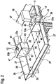
- the Fig. 2 shows perspective views of several lid boxes 47 and several lids 41.
- Each of the lid boxes 47 extends up to the edge 35 of the protective roof 21, the side of the lid box 47 facing the associated wall 4 being open. Furthermore, each of the lid boxes 47 is attached to the horizontally extending, central roof structure 23.
- the peripheral flank construction 25, which runs obliquely to the horizontal, is fastened laterally via the flank walls 27 to the respective cover box 47.
- the guide rails 12 have a T-shaped cross section.
- a corresponding shape of the cover openings 43 is also T-shaped.
- Each of the cover openings 43 is shaped in such a way that only a narrow gap remains between the respective guide rail 12 and the edge of the cover openings 43, which for example has a maximum width of less than 30 mm, such as approximately 10 mm. It is possible for one lid to have several Has cover openings 43, or that several guide rails 12 run through a rail opening 37, 39.
- a cover 41 can be divided into two or more cover parts 53a, 53b, between which (apart from the cover openings 43) only a slot (for example narrower than 10 mm) is formed when the cover 41 is located on the rail opening 39.
- these cover parts 53a, 53b can overlap.
- cover opening 43 or one cover opening 43 is formed completely within a cover part 53, the other cover part 53b merely providing an edge of the cover opening 43.
- the cover opening 43 is formed by two cover parts 53a, 53b.
- each of the cover parts 53a, 53b can be connected to the cover box 47 via a hinge 55.
- the hinges 55 are arranged in such a way that the hinge axis 57 runs essentially orthogonally to the wall 4 or the edge 35 of the protective roof 21, next to which the cover 41 is arranged.
- the slot 59 separating the cover parts 53a, 53b also runs essentially orthogonally to the wall 4 or the edge 35 of the protective roof 21.
- the cover parts 53a, 53b can thus be folded outwards along the wall 4 or the edge 35, as through the arrows are indicated.
- the rail clip 45 protrudes from the wall 4 and clasps a base of the guide rail 12.
- the rail opening 39 which is formed as a rectangular opening in the central roof structure 23, is located on the edge of the central roof structure 23.
Landscapes
- Engineering & Computer Science (AREA)
- Structural Engineering (AREA)
- Civil Engineering (AREA)
- Mechanical Engineering (AREA)
- Automation & Control Theory (AREA)
- Types And Forms Of Lifts (AREA)
- Lift-Guide Devices, And Elevator Ropes And Cables (AREA)
- Fittings On The Vehicle Exterior For Carrying Loads, And Devices For Holding Or Mounting Articles (AREA)
Claims (14)
- Installation d'ascenseur (1), comprenant
une plate-forme élévatrice (11) destinée à être fixée à une pluralité de positions de fixation dans une cage d'ascenseur (3),
au moins un rail de guidage (12) pour guider verticalement une cabine d'ascenseur (5) dans la cage d'ascenseur (3), le rail de guidage (12) pouvant être fixé à une paroi latérale (4) de la cage d'ascenseur au moyen d'un crampon de rail (45),
caractérisée en ce que la plate-forme élévatrice (11) présente un toit de protection (21) qui est conçu pour protéger la plate-forme élévatrice (11) de chutes d'objets,
le toit protecteur (21) présentant une ouverture de rail (39) à travers laquelle passe le rail de guidage (12), une section transversale du crampon de rail (45) étant agencée entièrement à l'intérieur de la section transversale de l'ouverture de rail (39),
le toit de protection (21) présentant un couvercle (41) pour recouvrir l'ouverture de rail (39), laquelle présente une ouverture de couvercle (43) à travers laquelle passe le rail de guidage (12). - Installation d'ascenseur (1) selon la revendication 1, l'ouverture de couvercle (43) présentant une forme qui correspond à une section transversale du rail de guidage (12).
- Installation d'ascenseur (1) selon la revendication 1 ou 2, l'ouverture de couvercle (43) et une section transversale du rail de guidage (12) étant en forme de T.
- Installation d'ascenseur (1) selon l'une des revendications précédentes, l'ouverture de couvercle (43) étant réalisée de telle sorte qu'un espace d'une largeur maximale de 30 mm existe entre le couvercle (41) et le rail de guidage (12).
- Installation d'ascenseur (1) selon l'une des revendications précédentes, le couvercle (41) étant formé d'au moins deux parties de couvercle (53a, 53b).
- Installation d'ascenseur (1) selon la revendication 5, l'ouverture de couvercle (41) étant fournie par une seule partie de couvercle ou l'ouverture de couvercle (41) étant fournie par deux des parties de couvercle.
- Installation d'ascenseur (1) selon l'une des revendications précédentes, le couvercle (41) étant fixé au toit de protection (21) au moyen de charnières (55).
- Installation d'ascenseur (1) selon l'une des revendications précédentes, le couvercle (41) étant disposé sur un bord (35) du toit de protection (21) et le couvercle (41) ou les parties de couvercle (53a, 53b) du couvercle (41) pouvant pivoter vers le haut autour d'un axe de charnière (57) parallèlement au bord et/ou orthogonalement au bord.
- Installation d'ascenseur (1) selon l'une des revendications précédentes, le toit de protection (21) comprenant une structure de toit centrale (23) s'étendant horizontalement ; le couvercle (41) étant disposé au moins sur certaines parties sur la structure de toit centrale (23).
- Système d'ascenseur (1) selon l'une des revendications précédentes, le toit de protection (21) présentant une structure de flancs périphérique (25) s'étendant obliquement par rapport à l'horizontale, le couvercle (41) étant disposé au moins sur certaines parties sur la structure de flancs périphérique (25).
- Installation d'ascenseur (1) selon l'une des revendications précédentes, le couvercle (41) étant placé sur un boîtier de couvercle (47) qui est fixé au toit de protection (21).
- Installation d'ascenseur (1) selon la revendication 11, le boîtier de couvercle (47) s'étendant jusqu'à un bord (35) du toit de protection (21).
- Installation d'ascenseur (1) selon la revendication 11 ou 12, le boîtier de couvercle (47),sur lequel est placé le couvercle (41) étant fixé sur une structure de toit centrale (23) s'étendant horizontalement et une structure de flancs périphérique (25) s'étendant obliquement par rapport à l'horizontale étant fixée sur un côté du boîtier de couvercle (47).
- Installation d'ascenseur selon l'une des revendications précédentes, comprenant en outre
une cabine d'ascenseur (5),
un moyen de support (9),
la cabine d'ascenseur (5) étant maintenue par le moyen de support (9) et pouvant être déplacée à l'intérieur de la cage d'ascenseur (3) le long de l'au moins un rail de guidage (12) à l'aide du moyen de support (9), le moyen de support (9) étant maintenu sur la plate-forme élévatrice (11) et le toit de protection (21) étant disposé au-dessus des éléments à protéger (15) de la plate-forme élévatrice (11).
Applications Claiming Priority (2)
| Application Number | Priority Date | Filing Date | Title |
|---|---|---|---|
| EP16177327 | 2016-06-30 | ||
| PCT/EP2017/065918 WO2018002093A1 (fr) | 2016-06-30 | 2017-06-27 | Installation d'ascenseur, se présentant en particulier sous forme d'un système de levage à grimpage, comprenant un toit protecteur de conception spéciale |
Publications (2)
| Publication Number | Publication Date |
|---|---|
| EP3478619A1 EP3478619A1 (fr) | 2019-05-08 |
| EP3478619B1 true EP3478619B1 (fr) | 2021-08-04 |
Family
ID=56292545
Family Applications (1)
| Application Number | Title | Priority Date | Filing Date |
|---|---|---|---|
| EP17732927.3A Active EP3478619B1 (fr) | 2016-06-30 | 2017-06-27 | Installation d'ascenseur, plus particulièrement sous la forme d'un système de levage d'escalade avec toit de protection spécialement conçu |
Country Status (6)
| Country | Link |
|---|---|
| US (1) | US11345571B2 (fr) |
| EP (1) | EP3478619B1 (fr) |
| CN (1) | CN109476455B (fr) |
| AU (1) | AU2017289122B2 (fr) |
| SG (1) | SG11201810828TA (fr) |
| WO (1) | WO2018002093A1 (fr) |
Families Citing this family (6)
| Publication number | Priority date | Publication date | Assignee | Title |
|---|---|---|---|---|
| PL3478621T3 (pl) * | 2016-06-30 | 2021-03-22 | Inventio Ag | Sposób wznoszenia instalacji windowej z możliwą do dopasowania użytkową wysokością podnoszenia |
| US11053098B2 (en) * | 2016-11-30 | 2021-07-06 | Inventio Ag | Elevator system and method for constructing such an elevator system |
| EP3691985B1 (fr) * | 2017-10-06 | 2021-07-07 | Inventio AG | Procédé de construction d'un ascenseur à hauteur de levage croissante |
| CN110092264B (zh) * | 2019-04-29 | 2022-04-05 | 北京天恒建设集团有限公司 | 一种建筑施工阶段电梯井内的物料提升系统 |
| US12071325B2 (en) * | 2020-03-12 | 2024-08-27 | Inventio Ag | Method for forming a guide structure for guiding an elevator car in an elevator shaft |
| CN112125090B (zh) * | 2020-10-14 | 2022-08-09 | 广州塞维拉电梯轨道系统有限公司 | 一种间隙可调式压码 |
Family Cites Families (9)
| Publication number | Priority date | Publication date | Assignee | Title |
|---|---|---|---|---|
| FR2694279A1 (fr) * | 1992-08-03 | 1994-02-04 | Otis Elevator Co | Ascenseur ou monte-charges, suivant l'avancement du gros-Óoeuvre de la construction de bâtiments. |
| KR100257681B1 (ko) * | 1997-03-29 | 2000-07-01 | 이종수 | 엘리베이터의 커버장치 |
| US7635049B2 (en) * | 2002-12-02 | 2009-12-22 | Kone Corporation | Method and apparatus for installing an elevator during the construction of a building |
| US9561934B2 (en) * | 2009-03-13 | 2017-02-07 | Otis Elevator Company | Elevator system with guide rail bracket |
| FI20100223A0 (fi) * | 2010-05-28 | 2010-05-28 | Kone Corp | Menetelmä ja hissijärjestely |
| EP2636629B1 (fr) * | 2012-03-06 | 2015-05-06 | KONE Corporation | Procédé et agencement d'ascenseur |
| WO2013170439A1 (fr) * | 2012-05-15 | 2013-11-21 | Otis Elevator Company | Système d'ascenseur |
| FR3007008B1 (fr) * | 2013-06-13 | 2015-07-17 | Thyssenkrupp Elevator Mfg F | Procede d'installation d'un moteur d'une installation d'ascenseur |
| RU2652340C2 (ru) | 2013-07-10 | 2018-04-25 | Инвенцио Аг | Страховочное устройство для платформы |
-
2017
- 2017-06-27 US US16/310,596 patent/US11345571B2/en active Active
- 2017-06-27 SG SG11201810828TA patent/SG11201810828TA/en unknown
- 2017-06-27 WO PCT/EP2017/065918 patent/WO2018002093A1/fr unknown
- 2017-06-27 EP EP17732927.3A patent/EP3478619B1/fr active Active
- 2017-06-27 CN CN201780040728.9A patent/CN109476455B/zh active Active
- 2017-06-27 AU AU2017289122A patent/AU2017289122B2/en active Active
Non-Patent Citations (1)
| Title |
|---|
| None * |
Also Published As
| Publication number | Publication date |
|---|---|
| CN109476455B (zh) | 2020-10-09 |
| CN109476455A (zh) | 2019-03-15 |
| US11345571B2 (en) | 2022-05-31 |
| WO2018002093A1 (fr) | 2018-01-04 |
| AU2017289122B2 (en) | 2020-04-30 |
| AU2017289122A1 (en) | 2019-01-17 |
| SG11201810828TA (en) | 2019-01-30 |
| US20190330022A1 (en) | 2019-10-31 |
| EP3478619A1 (fr) | 2019-05-08 |
Similar Documents
| Publication | Publication Date | Title |
|---|---|---|
| EP3478619B1 (fr) | Installation d'ascenseur, plus particulièrement sous la forme d'un système de levage d'escalade avec toit de protection spécialement conçu | |
| EP3478620B1 (fr) | Installation d'ascenseur, plus particulièrement sous la forme d'un système de levage d'escalade avec toit de protection spécialement conçu | |
| DE69935620T2 (de) | Aufzug | |
| DE2400313C3 (de) | Hilfseinrichtung für Montage- und Wartungsarbeiten an einem Kühlturm | |
| EP3541734B1 (fr) | Cabine d'ascenseur | |
| EP3679206B1 (fr) | Système de protection anti-chute comprenant un socle de support | |
| EP4222097B1 (fr) | Système d'ascenseur | |
| DE60208043T2 (de) | Verfahren und anordnung zur bildung eines sicherheitsraums im unteren teil eines aufzugschachts | |
| EP2102088B1 (fr) | Cabine d'ascenseur pour hauteurs de plafond de gaine réduites | |
| EP3356272B1 (fr) | Système d'ascenseur | |
| EP3645443B1 (fr) | Système d'ascenseur | |
| EP2281980B1 (fr) | Ferrure de plinthe | |
| DE102008055745B4 (de) | Lamellenführungsbolzen einer Lamelle einer Gebäudeöffnungsbeschattungsvorrichtung und Gebäudeöffnungsbeschattungsvorrichtung | |
| DE2255528C3 (de) | Vorrichtung zur Minderung von Schwingungen der Förderseile einer Aufzugsanlage | |
| EP3560882B1 (fr) | Passage pour un ascenseur | |
| EP3378821A1 (fr) | Dispositif de protection de personnes dans une cage d'ascenseur contre la chute éventuelle d'objets | |
| EP3683178A1 (fr) | Mât avec ascenseur et sécurité personnelle, en particulier mât de grue pour une grue à tour | |
| DE1918773C3 (de) | Aus Bauteilen zusammensetzbare, aufhängbare und in Abschnitten verlängerbare Arbeltsbühne | |
| DE202010016127U1 (de) | Vorrichtung zum Anlegen eines Wasserfahrzeuges an einem Wasserbauwerk | |
| EP2818608B1 (fr) | Échafaudage en consoles constituée de plusieurs éléments de consoles juxtaposés le long de la face arrière d'un premier élément de coffrage | |
| AT517030B1 (de) | Schwimmbecken | |
| DE1212707B (de) | Arbeitsverfahren mit Schutznetzen beim Errichten von Gebaeuden nach der Tafelbauweise | |
| WO2024132536A1 (fr) | Plateforme pour système d'ascenseur pour bâtiment en construction | |
| DE202013011064U1 (de) | Absperrvorrichtung | |
| EP4108619A1 (fr) | Cage d'ascenseur pour une installation d'ascenseur dans un bâtiment |
Legal Events
| Date | Code | Title | Description |
|---|---|---|---|
| STAA | Information on the status of an ep patent application or granted ep patent |
Free format text: STATUS: UNKNOWN |
|
| STAA | Information on the status of an ep patent application or granted ep patent |
Free format text: STATUS: THE INTERNATIONAL PUBLICATION HAS BEEN MADE |
|
| PUAI | Public reference made under article 153(3) epc to a published international application that has entered the european phase |
Free format text: ORIGINAL CODE: 0009012 |
|
| STAA | Information on the status of an ep patent application or granted ep patent |
Free format text: STATUS: REQUEST FOR EXAMINATION WAS MADE |
|
| 17P | Request for examination filed |
Effective date: 20181115 |
|
| AK | Designated contracting states |
Kind code of ref document: A1 Designated state(s): AL AT BE BG CH CY CZ DE DK EE ES FI FR GB GR HR HU IE IS IT LI LT LU LV MC MK MT NL NO PL PT RO RS SE SI SK SM TR |
|
| AX | Request for extension of the european patent |
Extension state: BA ME |
|
| DAV | Request for validation of the european patent (deleted) | ||
| DAX | Request for extension of the european patent (deleted) | ||
| STAA | Information on the status of an ep patent application or granted ep patent |
Free format text: STATUS: EXAMINATION IS IN PROGRESS |
|
| 17Q | First examination report despatched |
Effective date: 20200506 |
|
| STAA | Information on the status of an ep patent application or granted ep patent |
Free format text: STATUS: EXAMINATION IS IN PROGRESS |
|
| GRAP | Despatch of communication of intention to grant a patent |
Free format text: ORIGINAL CODE: EPIDOSNIGR1 |
|
| STAA | Information on the status of an ep patent application or granted ep patent |
Free format text: STATUS: GRANT OF PATENT IS INTENDED |
|
| INTG | Intention to grant announced |
Effective date: 20210304 |
|
| GRAS | Grant fee paid |
Free format text: ORIGINAL CODE: EPIDOSNIGR3 |
|
| GRAA | (expected) grant |
Free format text: ORIGINAL CODE: 0009210 |
|
| STAA | Information on the status of an ep patent application or granted ep patent |
Free format text: STATUS: THE PATENT HAS BEEN GRANTED |
|
| AK | Designated contracting states |
Kind code of ref document: B1 Designated state(s): AL AT BE BG CH CY CZ DE DK EE ES FI FR GB GR HR HU IE IS IT LI LT LU LV MC MK MT NL NO PL PT RO RS SE SI SK SM TR |
|
| REG | Reference to a national code |
Ref country code: GB Ref legal event code: FG4D Free format text: NOT ENGLISH |
|
| REG | Reference to a national code |
Ref country code: AT Ref legal event code: REF Ref document number: 1416803 Country of ref document: AT Kind code of ref document: T Effective date: 20210815 |
|
| REG | Reference to a national code |
Ref country code: CH Ref legal event code: EP |
|
| REG | Reference to a national code |
Ref country code: DE Ref legal event code: R096 Ref document number: 502017011104 Country of ref document: DE |
|
| REG | Reference to a national code |
Ref country code: IE Ref legal event code: FG4D Free format text: LANGUAGE OF EP DOCUMENT: GERMAN |
|
| REG | Reference to a national code |
Ref country code: LT Ref legal event code: MG9D |
|
| REG | Reference to a national code |
Ref country code: NL Ref legal event code: MP Effective date: 20210804 |
|
| PG25 | Lapsed in a contracting state [announced via postgrant information from national office to epo] |
Ref country code: HR Free format text: LAPSE BECAUSE OF FAILURE TO SUBMIT A TRANSLATION OF THE DESCRIPTION OR TO PAY THE FEE WITHIN THE PRESCRIBED TIME-LIMIT Effective date: 20210804 Ref country code: RS Free format text: LAPSE BECAUSE OF FAILURE TO SUBMIT A TRANSLATION OF THE DESCRIPTION OR TO PAY THE FEE WITHIN THE PRESCRIBED TIME-LIMIT Effective date: 20210804 Ref country code: SE Free format text: LAPSE BECAUSE OF FAILURE TO SUBMIT A TRANSLATION OF THE DESCRIPTION OR TO PAY THE FEE WITHIN THE PRESCRIBED TIME-LIMIT Effective date: 20210804 Ref country code: ES Free format text: LAPSE BECAUSE OF FAILURE TO SUBMIT A TRANSLATION OF THE DESCRIPTION OR TO PAY THE FEE WITHIN THE PRESCRIBED TIME-LIMIT Effective date: 20210804 Ref country code: FI Free format text: LAPSE BECAUSE OF FAILURE TO SUBMIT A TRANSLATION OF THE DESCRIPTION OR TO PAY THE FEE WITHIN THE PRESCRIBED TIME-LIMIT Effective date: 20210804 Ref country code: PT Free format text: LAPSE BECAUSE OF FAILURE TO SUBMIT A TRANSLATION OF THE DESCRIPTION OR TO PAY THE FEE WITHIN THE PRESCRIBED TIME-LIMIT Effective date: 20211206 Ref country code: NO Free format text: LAPSE BECAUSE OF FAILURE TO SUBMIT A TRANSLATION OF THE DESCRIPTION OR TO PAY THE FEE WITHIN THE PRESCRIBED TIME-LIMIT Effective date: 20211104 Ref country code: LT Free format text: LAPSE BECAUSE OF FAILURE TO SUBMIT A TRANSLATION OF THE DESCRIPTION OR TO PAY THE FEE WITHIN THE PRESCRIBED TIME-LIMIT Effective date: 20210804 Ref country code: BG Free format text: LAPSE BECAUSE OF FAILURE TO SUBMIT A TRANSLATION OF THE DESCRIPTION OR TO PAY THE FEE WITHIN THE PRESCRIBED TIME-LIMIT Effective date: 20211104 |
|
| PG25 | Lapsed in a contracting state [announced via postgrant information from national office to epo] |
Ref country code: PL Free format text: LAPSE BECAUSE OF FAILURE TO SUBMIT A TRANSLATION OF THE DESCRIPTION OR TO PAY THE FEE WITHIN THE PRESCRIBED TIME-LIMIT Effective date: 20210804 Ref country code: LV Free format text: LAPSE BECAUSE OF FAILURE TO SUBMIT A TRANSLATION OF THE DESCRIPTION OR TO PAY THE FEE WITHIN THE PRESCRIBED TIME-LIMIT Effective date: 20210804 Ref country code: GR Free format text: LAPSE BECAUSE OF FAILURE TO SUBMIT A TRANSLATION OF THE DESCRIPTION OR TO PAY THE FEE WITHIN THE PRESCRIBED TIME-LIMIT Effective date: 20211105 |
|
| PG25 | Lapsed in a contracting state [announced via postgrant information from national office to epo] |
Ref country code: NL Free format text: LAPSE BECAUSE OF FAILURE TO SUBMIT A TRANSLATION OF THE DESCRIPTION OR TO PAY THE FEE WITHIN THE PRESCRIBED TIME-LIMIT Effective date: 20210804 |
|
| PG25 | Lapsed in a contracting state [announced via postgrant information from national office to epo] |
Ref country code: DK Free format text: LAPSE BECAUSE OF FAILURE TO SUBMIT A TRANSLATION OF THE DESCRIPTION OR TO PAY THE FEE WITHIN THE PRESCRIBED TIME-LIMIT Effective date: 20210804 |
|
| REG | Reference to a national code |
Ref country code: DE Ref legal event code: R097 Ref document number: 502017011104 Country of ref document: DE |
|
| PG25 | Lapsed in a contracting state [announced via postgrant information from national office to epo] |
Ref country code: SM Free format text: LAPSE BECAUSE OF FAILURE TO SUBMIT A TRANSLATION OF THE DESCRIPTION OR TO PAY THE FEE WITHIN THE PRESCRIBED TIME-LIMIT Effective date: 20210804 Ref country code: SK Free format text: LAPSE BECAUSE OF FAILURE TO SUBMIT A TRANSLATION OF THE DESCRIPTION OR TO PAY THE FEE WITHIN THE PRESCRIBED TIME-LIMIT Effective date: 20210804 Ref country code: RO Free format text: LAPSE BECAUSE OF FAILURE TO SUBMIT A TRANSLATION OF THE DESCRIPTION OR TO PAY THE FEE WITHIN THE PRESCRIBED TIME-LIMIT Effective date: 20210804 Ref country code: EE Free format text: LAPSE BECAUSE OF FAILURE TO SUBMIT A TRANSLATION OF THE DESCRIPTION OR TO PAY THE FEE WITHIN THE PRESCRIBED TIME-LIMIT Effective date: 20210804 Ref country code: CZ Free format text: LAPSE BECAUSE OF FAILURE TO SUBMIT A TRANSLATION OF THE DESCRIPTION OR TO PAY THE FEE WITHIN THE PRESCRIBED TIME-LIMIT Effective date: 20210804 Ref country code: AL Free format text: LAPSE BECAUSE OF FAILURE TO SUBMIT A TRANSLATION OF THE DESCRIPTION OR TO PAY THE FEE WITHIN THE PRESCRIBED TIME-LIMIT Effective date: 20210804 |
|
| PLBE | No opposition filed within time limit |
Free format text: ORIGINAL CODE: 0009261 |
|
| STAA | Information on the status of an ep patent application or granted ep patent |
Free format text: STATUS: NO OPPOSITION FILED WITHIN TIME LIMIT |
|
| 26N | No opposition filed |
Effective date: 20220506 |
|
| PG25 | Lapsed in a contracting state [announced via postgrant information from national office to epo] |
Ref country code: SI Free format text: LAPSE BECAUSE OF FAILURE TO SUBMIT A TRANSLATION OF THE DESCRIPTION OR TO PAY THE FEE WITHIN THE PRESCRIBED TIME-LIMIT Effective date: 20210804 |
|
| PG25 | Lapsed in a contracting state [announced via postgrant information from national office to epo] |
Ref country code: MC Free format text: LAPSE BECAUSE OF FAILURE TO SUBMIT A TRANSLATION OF THE DESCRIPTION OR TO PAY THE FEE WITHIN THE PRESCRIBED TIME-LIMIT Effective date: 20210804 |
|
| REG | Reference to a national code |
Ref country code: BE Ref legal event code: MM Effective date: 20220630 |
|
| PG25 | Lapsed in a contracting state [announced via postgrant information from national office to epo] |
Ref country code: LU Free format text: LAPSE BECAUSE OF NON-PAYMENT OF DUE FEES Effective date: 20220627 Ref country code: IE Free format text: LAPSE BECAUSE OF NON-PAYMENT OF DUE FEES Effective date: 20220627 |
|
| PG25 | Lapsed in a contracting state [announced via postgrant information from national office to epo] |
Ref country code: BE Free format text: LAPSE BECAUSE OF NON-PAYMENT OF DUE FEES Effective date: 20220630 |
|
| PG25 | Lapsed in a contracting state [announced via postgrant information from national office to epo] |
Ref country code: IT Free format text: LAPSE BECAUSE OF NON-PAYMENT OF DUE FEES Effective date: 20220627 |
|
| REG | Reference to a national code |
Ref country code: AT Ref legal event code: MM01 Ref document number: 1416803 Country of ref document: AT Kind code of ref document: T Effective date: 20220627 |
|
| PG25 | Lapsed in a contracting state [announced via postgrant information from national office to epo] |
Ref country code: AT Free format text: LAPSE BECAUSE OF NON-PAYMENT OF DUE FEES Effective date: 20220627 |
|
| PGFP | Annual fee paid to national office [announced via postgrant information from national office to epo] |
Ref country code: CH Payment date: 20230702 Year of fee payment: 7 |
|
| PG25 | Lapsed in a contracting state [announced via postgrant information from national office to epo] |
Ref country code: HU Free format text: LAPSE BECAUSE OF FAILURE TO SUBMIT A TRANSLATION OF THE DESCRIPTION OR TO PAY THE FEE WITHIN THE PRESCRIBED TIME-LIMIT; INVALID AB INITIO Effective date: 20170627 |
|
| PG25 | Lapsed in a contracting state [announced via postgrant information from national office to epo] |
Ref country code: MK Free format text: LAPSE BECAUSE OF FAILURE TO SUBMIT A TRANSLATION OF THE DESCRIPTION OR TO PAY THE FEE WITHIN THE PRESCRIBED TIME-LIMIT Effective date: 20210804 Ref country code: CY Free format text: LAPSE BECAUSE OF FAILURE TO SUBMIT A TRANSLATION OF THE DESCRIPTION OR TO PAY THE FEE WITHIN THE PRESCRIBED TIME-LIMIT Effective date: 20210804 |
|
| PGFP | Annual fee paid to national office [announced via postgrant information from national office to epo] |
Ref country code: GB Payment date: 20240618 Year of fee payment: 8 |
|
| PGFP | Annual fee paid to national office [announced via postgrant information from national office to epo] |
Ref country code: DE Payment date: 20240627 Year of fee payment: 8 |
|
| PGFP | Annual fee paid to national office [announced via postgrant information from national office to epo] |
Ref country code: FR Payment date: 20240625 Year of fee payment: 8 |