EP3477932A1 - Farbtrennungsverarbeitungsvorrichtung, farbtrennungsverarbeitungsverfahren, verfahren zur erzeugung von farbtrennungsnachschlagetabellen und programm - Google Patents
Farbtrennungsverarbeitungsvorrichtung, farbtrennungsverarbeitungsverfahren, verfahren zur erzeugung von farbtrennungsnachschlagetabellen und programm Download PDFInfo
- Publication number
- EP3477932A1 EP3477932A1 EP17815038.9A EP17815038A EP3477932A1 EP 3477932 A1 EP3477932 A1 EP 3477932A1 EP 17815038 A EP17815038 A EP 17815038A EP 3477932 A1 EP3477932 A1 EP 3477932A1
- Authority
- EP
- European Patent Office
- Prior art keywords
- ink
- color material
- amount
- virtual
- virtual color
- Prior art date
- Legal status (The legal status is an assumption and is not a legal conclusion. Google has not performed a legal analysis and makes no representation as to the accuracy of the status listed.)
- Granted
Links
- 238000000034 method Methods 0.000 title claims description 31
- 238000003672 processing method Methods 0.000 title claims description 3
- 238000000926 separation method Methods 0.000 title description 11
- 239000000463 material Substances 0.000 claims abstract description 545
- 238000006243 chemical reaction Methods 0.000 claims abstract description 223
- 238000009795 derivation Methods 0.000 claims abstract description 23
- 238000009499 grossing Methods 0.000 claims description 35
- 230000008859 change Effects 0.000 claims description 25
- 230000001747 exhibiting effect Effects 0.000 claims 1
- 230000002349 favourable effect Effects 0.000 abstract description 7
- 239000000976 ink Substances 0.000 description 595
- 230000014509 gene expression Effects 0.000 description 88
- 238000010586 diagram Methods 0.000 description 33
- 230000003595 spectral effect Effects 0.000 description 18
- 239000003086 colorant Substances 0.000 description 9
- 238000004364 calculation method Methods 0.000 description 8
- 230000004048 modification Effects 0.000 description 5
- 238000012986 modification Methods 0.000 description 5
- 230000003287 optical effect Effects 0.000 description 4
- 238000010521 absorption reaction Methods 0.000 description 3
- 239000011159 matrix material Substances 0.000 description 3
- 101100537098 Mus musculus Alyref gene Proteins 0.000 description 2
- 101100269674 Mus musculus Alyref2 gene Proteins 0.000 description 2
- 241000533901 Narcissus papyraceus Species 0.000 description 2
- 101150095908 apex1 gene Proteins 0.000 description 2
- 238000004040 coloring Methods 0.000 description 2
- 239000002131 composite material Substances 0.000 description 2
- 230000006866 deterioration Effects 0.000 description 2
- 230000031700 light absorption Effects 0.000 description 2
- 238000002156 mixing Methods 0.000 description 2
- 230000009897 systematic effect Effects 0.000 description 2
- 238000012935 Averaging Methods 0.000 description 1
- 229910000906 Bronze Inorganic materials 0.000 description 1
- 238000000149 argon plasma sintering Methods 0.000 description 1
- 230000008901 benefit Effects 0.000 description 1
- 239000010974 bronze Substances 0.000 description 1
- 230000000295 complement effect Effects 0.000 description 1
- KUNSUQLRTQLHQQ-UHFFFAOYSA-N copper tin Chemical compound [Cu].[Sn] KUNSUQLRTQLHQQ-UHFFFAOYSA-N 0.000 description 1
- 238000009792 diffusion process Methods 0.000 description 1
- 230000000694 effects Effects 0.000 description 1
- 239000010408 film Substances 0.000 description 1
- 238000001914 filtration Methods 0.000 description 1
- 239000000203 mixture Substances 0.000 description 1
- 230000009467 reduction Effects 0.000 description 1
- 238000000859 sublimation Methods 0.000 description 1
- 239000010409 thin film Substances 0.000 description 1
Images


Classifications
-
- B—PERFORMING OPERATIONS; TRANSPORTING
- B41—PRINTING; LINING MACHINES; TYPEWRITERS; STAMPS
- B41J—TYPEWRITERS; SELECTIVE PRINTING MECHANISMS, i.e. MECHANISMS PRINTING OTHERWISE THAN FROM A FORME; CORRECTION OF TYPOGRAPHICAL ERRORS
- B41J2/00—Typewriters or selective printing mechanisms characterised by the printing or marking process for which they are designed
- B41J2/525—Arrangement for multi-colour printing, not covered by group B41J2/21, e.g. applicable to two or more kinds of printing or marking process
-
- H—ELECTRICITY
- H04—ELECTRIC COMMUNICATION TECHNIQUE
- H04N—PICTORIAL COMMUNICATION, e.g. TELEVISION
- H04N1/00—Scanning, transmission or reproduction of documents or the like, e.g. facsimile transmission; Details thereof
- H04N1/46—Colour picture communication systems
- H04N1/54—Conversion of colour picture signals to a plurality of signals some of which represent particular mixed colours, e.g. for textile printing
-
- G—PHYSICS
- G06—COMPUTING; CALCULATING OR COUNTING
- G06F—ELECTRIC DIGITAL DATA PROCESSING
- G06F3/00—Input arrangements for transferring data to be processed into a form capable of being handled by the computer; Output arrangements for transferring data from processing unit to output unit, e.g. interface arrangements
- G06F3/12—Digital output to print unit, e.g. line printer, chain printer
-
- G—PHYSICS
- G06—COMPUTING; CALCULATING OR COUNTING
- G06T—IMAGE DATA PROCESSING OR GENERATION, IN GENERAL
- G06T1/00—General purpose image data processing
-
- H—ELECTRICITY
- H04—ELECTRIC COMMUNICATION TECHNIQUE
- H04N—PICTORIAL COMMUNICATION, e.g. TELEVISION
- H04N1/00—Scanning, transmission or reproduction of documents or the like, e.g. facsimile transmission; Details thereof
- H04N1/46—Colour picture communication systems
-
- H—ELECTRICITY
- H04—ELECTRIC COMMUNICATION TECHNIQUE
- H04N—PICTORIAL COMMUNICATION, e.g. TELEVISION
- H04N1/00—Scanning, transmission or reproduction of documents or the like, e.g. facsimile transmission; Details thereof
- H04N1/46—Colour picture communication systems
- H04N1/52—Circuits or arrangements for halftone screening
-
- H—ELECTRICITY
- H04—ELECTRIC COMMUNICATION TECHNIQUE
- H04N—PICTORIAL COMMUNICATION, e.g. TELEVISION
- H04N1/00—Scanning, transmission or reproduction of documents or the like, e.g. facsimile transmission; Details thereof
- H04N1/46—Colour picture communication systems
- H04N1/56—Processing of colour picture signals
- H04N1/60—Colour correction or control
Definitions
- the present invention relates to image processing to convert an image signal into a signal corresponding to a plurality of color material components that a printer handles.
- a printer represented by an ink jet printer or an electrophotographic printer, generates print data by receiving an image signal (normally, RGB color signal) as an input and converting the image signal into the amount of color material (e.g., ink of CMYK and toner) used in the printer.
- an image signal normally, RGB color signal
- the image quality such as gradation properties, color reproduction accuracy, and granularity, changes, and therefore, the conversion processing from an image signal into a color material amount is important.
- the three-dimensional LUT holds the color material amount of a printer corresponding to three-dimensional data of RGB, which is an input signal.
- the color material amount is calculated by the product-sum operation of the color material amount information stored at adjacent grid points including the RGB value desired to be found and the coefficient (weighting) in accordance with the RGB value desired to be found and the information on the distance between the adjacent grid points.
- the results of the calculation of the color material amount by the interpolation operation are affected by the color material amount information stored at the grid point, and therefore, in order to improve the image quality, such as gradation properties, color reproduction accuracy, and granularity, the setting of the color material amount stored at the grid point becomes important.
- Patent Document 1 has disclosed a technique to set a target color for each of a plurality of thinned grid points and to calculate the color material amount (ink amount) that implements each target color based on a color prediction model.
- the color material amount is determined with priority so that there is no inflection point between grid points, and thereby, a three-dimensional LUT whose gradation properties and granularity in the shadow area are favorable is created.
- Patent Literature 1 Japanese Patent Laid-Open No. 2015-142250
- the color material amount is determined independently for each grid point based on the color prediction model. At this time, it is necessary to determine the color material amounts in the number corresponding to the number of color materials (e.g. four to twelve) used in the printer. In general, the level of difficulty of color prediction for a large number of color materials is high and an error from the actual color is produced.
- an object of the present invention is to provide color conversion processing capable of obtaining favorable gradation properties in the entire color space from the shadow area to the highlight area.
- the color conversion processing apparatus is a color conversion processing apparatus that converts an input image signal value into an output value of an actual color material used in an image forming apparatus, and includes: a derivation unit configured to derive an output value corresponding to the input image signal value for a plurality of virtual color materials smaller in number than the number of actual color materials; and a conversion unit configured to convert the derived output values of the plurality of virtual color materials into the output values of the actual color materials, and each of the plurality of virtual color materials has a density corresponding to each wavelength band obtained by dividing a wavelength range reproduced by the actual color materials being output into a plurality of wavelength bands, and the derivation unit derives the output value corresponding to the input image signal value based on the density corresponding to each of the wavelength bands for the plurality of virtual color materials.
- the color conversion processing of the present invention it is possible to obtain favorable gradation properties in the entire color space from the shadow area to the highlight area.
- output values of virtual color materials for an input image signal value are derived first, whose each absorption wavelength band does not overlap another in principle.
- the color material amount of the virtual color material is derived so that the relationship between the input image signal value and the output value of the virtual color material is one that increases monotonically and causes no inflection point to occur or whose number of inflection points is as small as possible (whose secondary differential does not become negative).
- an ink jet printer is supposed and explanation is given by taking an aspect as an example in which for an input image signal, the amount of ink used in the printer is derived.
- the present invention is not limited to an ink jet printer and it is also possible to apply the present invention to other printing schemes, such as a thermal dye-sublimation printer, a laser printer, and a UV curable ink jet printer.
- FIG. 1 is a block diagram showing an example of a configuration of a printing system according to the present embodiment.
- the printing system in FIG. 1 includes, for example, an image processing apparatus 100, such as a general personal computer, and an image forming apparatus 200, such as the ink jet printer described above, and both are connected by a printer interface or a circuit.
- the image processing apparatus 100 includes a color matching processing unit 101, a color conversion processing unit 102, and a halftone processing unit 103 and each unit is implemented by a printer driver installed in the image processing apparatus 100.
- printing-target image data is processed first in the color matching processing unit 101.
- This image data is, for example, 8-bit RGB color image data.
- the color matching processing unit 101 performs color matching processing for the input RGB image data and corrects the color of the RGB image. By this color matching processing, even in the case where an image forming apparatus or a printing medium having various color reproduction characteristics is used, it is possible to obtain systematic color reproduction.
- a three-dimensional color matching lookup table (LUT) 110 stored in the HDD and the like, not shown schematically is referred to.
- the color matching LUT 110 for example, RGB values are described only on 17 ⁇ 17 ⁇ 17 grid points and a value between grid points is derived by linear interpolation and the like. It may also be possible to implement the color matching processing by holding a matrix for color matching in place of an LUT and by performing matrix conversion for the input RGB value.
- the RGB image data for which the color matching processing has been performed is sent to the color conversion processing unit 102.
- the color conversion processing unit 102 generates each image (ink value image) corresponding to each ink used in the image forming apparatus 200 from the RGB image data for which the color matching processing has been performed.
- a color conversion LUT 111 stored in the HDD and the like, not shown schematically is referred to and the RGB value, which is an input image signal, is converted into an output value of ink.
- FIG. 2 is a diagram of an RGB cube (color cube) schematically representing a color conversion LUT.
- an output value (ink amount) of each ink used in the image forming apparatus 200 is defined.
- Each of vertexes (0, 0, 0), (255, 0, 0), (0, 255, 0), (0, 0, 255), (0, 255, 255), (255, 0, 255), (255, 255, 0), and (255, 255, 255) of the color cube in FIG. 2 is a point corresponding to an input image signal.
- Each vertex (primary point) corresponds to a color of black (K), red (R), green (G), blue (B), cyan (C), magenta (M), yellow (Y), and white (W). Characteristics and a creation method of a color conversion LUT in the present embodiment will be described later.
- the halftone processing unit 103 converts the ink value image of each color obtained by the color conversion processing unit 102 into a binary image (or image whose number of values is two or more and whose number of tone levels is smaller than the number of input tone levels) that can be handled by the image forming apparatus 200.
- a binary image or image whose number of values is two or more and whose number of tone levels is smaller than the number of input tone levels
- the halftone processing method mention is made of the publicly known dither matrix method and error diffusion method.
- the binary image data generated by the halftone processing unit 103 is output to the image forming apparatus 200 and in the image forming apparatus 200, an image in accordance with the binary image data is formed on a printing medium, such as paper.
- an input image signal value here, RGB value
- a value indicating an ejection amount of ink, which is an actual color material.
- the gradation of an image formed by the image forming apparatus 200 also becomes smooth.
- the degree of smoothness of the ink value is derived by a feature amount based on a difference in, for example, the primary differential or the secondary differential.
- the color matching processing is, as described previously, processing to obtain systematic color reproduction for a printer and a printing medium having various color reproduction characteristics.
- the color matching LUT 110 to be used is determined so that the input RGB value and the color of an image to be formed match with each other.
- the color conversion LUT 111 is designed so that smooth ink values are obtained in the entire color area, it is made possible to obtain a printout whose color reproduction is guaranteed and whose gradation is smooth only by matching the input RGB value with the color of an image to be formed by the color matching LUT 110.
- the present embodiment proposes a color conversion method capable of guaranteeing smoothness of the output gradation for consecutive input RGB values.
- the color conversion method is designed so as to derive the ink value for the input RGB value. Because of this, the color of an image to be formed in accordance with the color conversion method according to the present embodiment does not necessarily match with the color indicated by the input image signal.
- the ink values derived in accordance with the color conversion method in the present embodiment are associated with discrete input image signal values obtained by appropriately thinning those in the range of 16 to 256 for each of the RGB axes. Then, the ink values are held as the color conversion LUT 111 and referred to in the color conversion processing in the color conversion processing unit 102.
- FIG. 3 is a flowchart showing a flow of color conversion processing according to the present embodiment.
- the output image density In order to implement smooth output gradation by the color conversion processing, it is necessary for the output image density to change smoothly for the input image signal. That is, in the case where it is possible to implement color conversion processing by which the output image density changes smoothly for the input image signal, it is possible to attain smooth output gradation.
- the larger the number of inks used in a printer the more difficult it becomes to derive the ink amount that causes the image density to change smoothly.
- virtual color materials in the number smaller than the number of inks used in the image forming apparatus 200 are defined and the virtual color material amount is found so that the characteristics of the output value of the virtual color material (virtual color material amount) for the input RGB value change smoothly in the entire color area (S301). As described above, it is desirable that the absorption wavelength bands corresponding to the respective color materials do not overlap one another. Then, the virtual color material amount that is found is converted into the ink value as the actual color material amount based on a conversion expression or a conversion table having substantially linear characteristics (S302).
- the case is considered where the input RGB value is converted into the ink amount of cyan (c), magenta (m), yellow (y), black (k), light cyan (lc), light magenta (1m), gray (gy), and red (r).
- an eight-dimensional ink amount (Wc, Wm, Wy, Wk, Wgy, Wlc, Wlm, Wr) is derived in accordance with the procedure shown in FIG. 3 .
- the virtual color material amount is explained.
- the virtual color materials are inks of three colors, i.e., yellow, magenta, and cyan, which are the three primary colors of the subtractive color mixture.
- a spectral reflectance Ref ( ⁇ ) is divided into n wavelength blocks and the values obtained by averaging the spectral reflectance within each wavelength block are defined as block reflectances Ref1, Ref2, ⁇ , Refn.
- values D1, D2, ⁇ , Dn obtained by converting the block reflectances Ref1, Ref2, ⁇ , Refn by expression (1) below are defined as block densities.
- Dx ⁇ log 10 Refx
- x is a subscript indicating 1 to n.
- the spectral reflectance Ref ( ⁇ ) is divided into three wavelength blocks corresponding to the wavelength bands that the above-described three color inks mainly absorb.
- the block density corresponding to the wavelength band (380 to 480 nm) that the yellow ink mainly absorbs is taken to be Dy.
- the block density corresponding to the wavelength band (480 to 580 nm) that the magenta ink mainly absorbs is taken to be Dm
- the block density corresponding to the wavelength band (580 to 730 nm) that the cyan ink mainly absorbs is taken to be Dc.
- FIG. 4(a) to FIG. 4(c) are each a graph representing the spectral reflectance of the virtual color material.
- FIG. 4(a) shows that the virtual color material yi absorbs only the wavelength band (380 to 480 nm) that the yellow ink mainly absorbs and reflects 100% of the light of wavelengths outside the wavelength band.
- FIG. 4(a) shows that the virtual color material yi absorbs only the wavelength band (380 to 480 nm) that the yellow ink mainly absorbs and reflects 100% of the light of wavelengths outside the wavelength band.
- FIG. 4(b) shows that the virtual color material mi absorbs only the wavelength band (480 to 580 nm) that the magenta ink mainly absorbs and
- FIG. 4(c) shows that the virtual color material ci absorbs only the wavelength band (580 to 730 nm) that the cyan ink mainly absorbs.
- each block density of yi, mi, and ci is proportional to the color material amount per unit area on the printing medium. That is, it is possible to perform linear conversion mutually between the arbitrary block densities Dy, Dm, and Dc and virtual color material amounts Vyi[%], Vmi[%], and Vci[%] in accordance with expression (2-1) to expression (2-3) below.
- ⁇ _y is a constant of proportion in relation to the yellow density of the virtual color material yi and means that the larger the value thereof, the higher the yellow density per unit amount is.
- applied material amount the block density in a predetermined amount of material to be applied
- ⁇ _m is a constant of proportion in relation to the magenta density of the virtual color material mi
- ⁇ _c is a constant of proportion in relation to the cyan density of the virtual color material ci.
- the arbitrary spectral reflectance Ref ( ⁇ ) can be converted into the block densities Dy, Dm, and Dc by expression (1) described above after finding the block reflectance. Further, by expression (2-1) to expression (2-3) described above, it is possible to uniquely convert the block density into each of the virtual color material amounts Vyi, Vmi, and Vci. Then, in the present embodiment, the output value of each ink, which is the actual color material, is derived so that the above-described virtual color material amounts Vyi, Vmi, and Vci change smoothly for the input image signal (here, three channels of RGB).
- the spectral reflectance of the virtual color material is not limited to the above-described example and for example, it may also be possible to define the spectral reflectance of the virtual color material by narrowing the wavelength band in which the virtual color material has a density so that the virtual color material has a density only in part of the wavelength band (e.g., the virtual color material yi absorbs only wavelengths of 400 to 460 nm). Further, on the contrary, it may also be possible to define the spectral reflectance of the virtual color material so that two or more virtual materials have a density for the same wavelengths by widening the wavelength band. As described above, it is premised that the virtual color materials do not overlap in the absorption wavelength band.
- the reflectance Ref of each virtual color material is defined as 10% in the wavelength band that the virtual color material mainly absorbs, and as 100% in the other wavelength bands and the block density is set to 0.0 or 1.0.
- the reflectance and the block density of the virtual color material are not limited to the above and other values may be used.
- the number of virtual color materials is not limited to three and may be three or more and less than the number of inks used in the image forming apparatus 200.
- the image forming apparatus 200 includes five color inks as in the present embodiment, for example, it may also be possible to define block densities that equally divide the wavelength range (e.g., 380 to 730 nm) reproduced by the ink, which is the actual color material, into four ranges and to define a virtual color material corresponding to each of the four ranges.
- the width of the wavelength band may be a width of a wavelength band narrower than 380 to 730 nm or may be a width of a wider wavelength band including another wavelength band.
- FIG. 6 is a flowchart showing details of the virtual color material amount derivation processing according to the present embodiment.
- block densities T_Dy, T_Dm, and T_Dc that are targets for an input image signal are set, respectively.
- an input image signal is input as an RGB value on an sRGB space.
- B_max, G_max, and R_max are the maximum values that the input RGB value can take, respectively.
- T_Dm -2 log ⁇ (1 / G_max) ⁇ 2.2 ⁇ + log ⁇ (2 / G_max) ⁇ 2.2 ⁇
- FIG. 7 shows an example of the target block densities T_Dy, T_Dm, and T_Dc on a W-Y line that connects the white primary point and the yellow primary point.
- the virtual color material amounts that implement the target block densities T_Dy, T_Dm, and T_Dc set at step 601 are derived.
- the virtual color materials yi, mi, and ci by expression (2-1) to expression (2-3) described previously, it is possible to linearly convert the block densities Dy, Dm, and Dc into the amounts Vyi, Vmi, and Vci of the virtual color materials yi, mi, and ci, respectively.
- FIG. 8 is a graph representing a relationship between the target block density T_Dy and the virtual color material amount Vyi that implements T_Dy in the case of following the above, and it is known that there is a linear relationship between the target block density T_Dy and the virtual color material amount Vyi.
- the above is the contents of the virtual color material amount derivation processing.
- the conversion processing from the virtual color material amount into the actual color material amount at step 302 described above is explained.
- the actual color material amounts are determined so that at least one of the virtual color material amounts Vyi, Vmi, and Vci does not exceed the virtual color material amount that is the source of conversion.
- the virtual color material amount is converted into the actual color material amount with the smoothness of the virtual color material amount being kept.
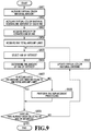
- FIG. 9 is a flowchart showing a flow of the conversion processing into the actual color material amount (ink amount) according to the present embodiment.
- the virtual color material amounts Vyi, Vmi, and Vci that are the source of conversion are acquired.
- FIG. 10 shows an example of the virtual color material amounts Vyi, Vmi, and Vci that are the source of conversion. The virtual color material amounts shown in FIG. 10 are found as follows.
- a probability that a dot is formed in a pixel obtained by dividing one square inch into 1,200 ⁇ 1,200 portions is supposed.
- virtual color material amounts Vyi_x, Vmi_x, and Vci_x in the case where an ink x as the actual color material is represented by equivalent virtual color materials are acquired.
- virtual color material equivalent amounts As described previously, it is possible to uniquely convert an arbitrary spectral reflectance into the amounts Vyi, Vmi, and Vci of the virtual color materials yi, mi, and ci by expression (1) and expression (2-1) to expression (2-3) described above.
- the spectral reflectance in the case of a unit amount W0[%] of the ink x, which is arbitrary, into the virtual color material equivalent amounts Vyi_x, Vmi_x, and Vci_x.
- the equivalent values of the virtual color materials per unit amount of the ink x, Vyi_x, Vmi_x, and Vci_x are acquired. Specifically, the procedure is as follows.
- the image forming apparatus 200 outputs print data whose applied material amount is W0[%].
- a spectral reflectance Refp ( ⁇ ) at the printed portion and a spectral reflectance Ref0 ( ⁇ ) at the paper white portion in the output printed matter are measured by using a colorimeter such as a spectral colorimeter. Further, by expression (4) below, the spectral reflectance Ref ( ⁇ ) of the ink is calculated.
- FIG. 11(e) each show an example of the virtual color material equivalent amounts of each ink.
- FIG. 11(a) shows the virtual color material equivalent amounts of the gray ink per unit applied material amount W0[%] described above.
- FIG. 11(b) shows the virtual color material equivalent amounts per unit applied material amount W0[%] of the cyan ink
- FIG. 11(c) shows those of the magenta ink
- FIG. 11(d) shows those of the yellow ink
- FIG. 11(e) shows those of the black ink, respectively.
- each ink amount W is found so that the virtual color material equivalent amounts of each ink coincide with the target virtual color material amounts Vyi_x, Vmi_x, and Vci_x.
- step 903 information on the priority of conversion of each ink used in the image forming apparatus 200 is acquired.
- the priority of conversion is set so that, for example, the ink whose density is lower is given higher priority.
- the priority of conversion in the case of each ink shown in Table 2 described above the priority is high in the order of gray, cyan, magenta, yellow, and black.
- the determination method of the priority of conversion is not limited to the above-described example.
- the conversion into the ink whose density is high is performed with priority, and therefore, it is possible to reduce the ink total amount.
- a desired requirement such as granularity, ink consumption, sharpness, and coloring of gloss.
- priority is given to sharpness
- priority is given to the high-density ink
- priority is given to coloring of gloss
- the value of a limit to the ink total amount (Max_W[%]) determined in advance is acquired.
- This value of the total amount limit Max_W is given by a designer.
- the limit value of the total amount is determined by the designer outputting a plurality of patches different in ink amount by the image forming apparatus 200 and finding the amount of ink that a printing medium can absorb without any problem.
- an ink on which attention is to be focused (ink of interest n) is selected from among all the inks. That is, from the inks used by the image forming apparatus 200, the ink that has not been selected yet as the ink of interest and whose priority is the highest is determined to be the ink of interest n.
- an ink amount Wn of the ink of interest n selected at step 905 is determined in accordance with Lambert's law.
- the ink amount of the ink of interest is determined so that at least one of the virtual color material amounts Vyi, Vmi, and Vci coincides with the virtual color material amount that is the source of conversion acquired at step 901. More specifically, ink amounts Wn_y, Wn_m, and Wn_c with which the virtual color material amounts Vyi, Vmi, and Vci are caused to coincide in the ink of interest n are found by using expression (5-1) to expression (5-3) below.
- Vyi_n, Vmi_n, and Vmi_n are the virtual color material equivalent amounts of the ink of interest n, respectively.
- ⁇ n_y is a constant.
- expression (5-2) and expression (5-3) described above into expression (5-2') and expression (5-3') below, respectively.
- ⁇ n_m W0 / (100 ⁇ Vmi_n)
- ⁇ n_c W0 / (100 ⁇ Vci_n).
- ⁇ n_y is a value relating a ratio of the virtual color material Vyi_n equivalent to the ink of interest n in the predetermined amount W0[%] to the virtual color material amount Vyi included in the virtual color material yi in the same amount (W0[%]). That is, it is shown that the larger ⁇ n_y, the smaller Vyi_n equivalent to the ink of interest n in the predetermined amount is. Consequently, it is meant that the larger ⁇ n_y, the larger the ink amount Wn becomes, which causes the virtual color material amount that is the source of conversion to coincide with the virtual color material equivalent amount of the ink of interest n.
- the ink amount Wn of the ink of interest is determined in accordance with the ink characteristics of the ink of interest n. Specifically, the maximum value is acquired for the virtual color material equivalent amounts Vyi_n, Vmi_n, and Vci_n of the ink of interest n is acquired and the ink amount that causes the virtual color material equivalent amount having the maximum value to coincide with the virtual color material amount that is the source of conversion is selected as Wn.
- Wn_y corresponding to Vyi_n whose virtual color material equivalent amount is the largest is taken to be the ink amount Wn of the ink of interest n.
- the amount of the main virtual color material of the ink of interest n e.g., in the case where the ink of interest is the yellow ink, the virtual color material amount Vyi
- the minimum value of Wn_y, Wn_m, and Wn_c is taken to be the ink amount Wn of the ink of interest n.
- the ink amount by taking into consideration each virtual color material amount. It may also be possible to find the maximum virtual color material amount from the virtual color material amounts acquired at step 901 and to select the ink amount that causes the virtual color material amount to coincide with the virtual color material that is the source of conversion as Wn irrespective of the ink characteristics.
- step 907 whether or not the accumulated value of the ink amounts determined for the ink of interest is within the range of the ink total amount limit Max_W acquired at step 904 is determined. Specifically, a total sum Sum_W of the ink amounts determined up to the present point in time and the ink total amount limit Max_W are compared and whether the total amount Sum_W is smaller than or equal to the total amount limit Max_W is determined. In the case where the results of the determination indicate that the total sum Sum_W is smaller than or equal to the total amount limit Max_W, the processing advances to step 909. On the other hand, in the case where the total sum Sum_W is larger than the total amount limit Max_W, the processing advances to step 908.
- ink replacement processing is performed.
- This processing is processing to convert the ink whose priority of conversion is high into the ink whose priority is lower and which exhibits substantially the same hue so that the accumulated ink amount (total sum Sum_W) and the ink total amount limit Max_W become equal to each other.
- the replacement is performed so that the virtual color material amount before the replacement substantially coincides with that after the replacement.
- the gray ink whose priority is high is replaced with the black ink whose priority is lower and which exhibits substantially the same hue.
- the replacement of the gray ink with the black ink is performed by using expression (6-1) and expression (6-2) below.
- Wgy ′ Wgy ⁇ Sum _ W ⁇ Max _ W ⁇ ⁇ / ⁇ ⁇ 1
- Wk ′ Wk + Sum _ W ⁇ Max _ W / ⁇ ⁇ 1
- Wgy and Wk' are the ink amount of the gray ink after the replacement and that of the black ink after the replacement, respectively.
- the ratio between the virtual color material equivalent amounts Vyi_n, Vmi_n, and Vci_n is regarded as substantially the same and the gray ink is replaced with the black ink by using a ratio of replacement ⁇ .
- the ratio of replacement ⁇ is found by, for example, V_k / V_gy.
- V_k is the total sum of virtual color material equivalent amounts Vyi_k, Vmi_k, and Vci_k of the black ink
- V_gy is the total sum of virtual color material equivalent amounts Vyi_gy, Vmi_gy, and Vci_gy.
- the ratio of replacement ⁇ for example, it may also be possible to acquire the maximum value of the virtual color material equivalent amounts Vyi_n, Vmi_n, and Vci_n and to use the ratio of the virtual color material equivalent amount having the maximum value.
- the ratio of the main virtual color material equivalent amount is important, and therefore, it is desirable to use the ratio of the virtual color material equivalent amount having the maximum value.
- step 909 whether or not all the inks used in the image forming apparatus 200 have already been selected as the ink of interest is determined. In the case where all the inks have already been selected as the ink of interest, this processing is terminated. On the other hand, in the case where the ink that has not been selected yet as the ink of interest exists, the processing advances to step 910.
- the virtual color material amounts that are the source of conversion are updated. Specifically, the virtual color material amounts are updated to virtual color material amounts Vyi", Vmi", and Vci” obtained by using expression (7-1) to expression (7-3) below.
- Vyi " Vyi ⁇ Vyi ′
- Vmi " Vmi ⁇ Vmi ′
- Vci " Vci ⁇ Vci ′
- Vyi, Vmi, and Vci are the virtual color material amounts acquired at step 901.
- each of Vyi', Vmi', and Vci' is the total sum of the virtual color material equivalent amounts, which is calculated from each ink amount W and the virtual color material equivalent amount obtained at step 906 or at step 908.
- Vyi' is ⁇ Wx + Vyi_x. It is assumed that the values of the virtual color material equivalent amounts Vyi", Vmi", and Vci" after the updating are taken to be values larger than or equal to 0 and in the case where the value becomes a negative value as the results of using expression (7-1) to expression (7-3) described above, the virtual color material equivalent amount after the updating is set to 0.
- Vyi", Vmi", and Vci" after the updating obtained as described above are used as the virtual color material amounts that are the targets of coincidence in the processing of the next ink of interest n.
- step 905 to step 910 the processing at each of step 905 to step 910 described above is explained by showing a specific example.
- the virtual color material equivalent amounts acquired at step 902 are values shown in FIG. 11(a) to FIG. 11(e) described previously.
- FIG. 12(a) to FIG. 12 (d') are diagrams showing a specific determination procedure.
- FIG. 12B -a shows the virtual color material amounts Vyi, Vmi, and Vci by the gray ink in the case where the virtual color material amount Vyi is caused to coincide by the virtual color material equivalent amounts of the gray ink shown in FIG. 11(a) .
- Wgy_c an ink amount Wgy_c is shown in FIG. 12 (d').
- Wgy_c 51.3[%]
- the ink amount Wgy of the gray ink and the ink total amount limit Max_W are compared (S907) and further, the ink replacement processing is performed in accordance with the necessity (S908).
- the determination of termination is performed (S909) and in the case where there is an unprocessed ink, the virtual color material amounts are updated (S910) and the processing by taking the next ink to be the ink of interest is repeated.
- FIG. 13(a) to FIG. 13(d) shows the "virtual color material amounts that are the source of conversion", the “virtual color material amounts by the ink of interest", the “ink amount of each ink”, and the "accumulated ink amount” in the first loop.
- the gray ink is selected (S905).
- FIG. 14(a) to FIG. 14(d) shows the "virtual color material amounts that are the source of conversion", the "virtual color material amounts by the ink of interest", the “ink amount of each ink”, and the "accumulated ink amount” in the second loop.
- the cyan ink is selected as the ink of interest (S905).
- an ink amount Wc_c that satisfies the virtual color material amount Vci corresponding to a maximum value Vci_c of the virtual color material equivalent amounts of the cyan ink is taken to be the ink amount Wc of the cyan ink.
- FIG. 15(a) to FIG. 15(d) shows the "virtual color material amounts that are the source of conversion", the “virtual color material amounts by the ink of interest", the “ink amount of each ink”, and the "accumulated ink amount” in the third loop.
- the magenta ink is selected as the ink of interest.
- an ink amount Wm_m that satisfies the virtual color material amount Vmi corresponding to a maximum value Vmi_m of the virtual color material equivalent amounts thereof is taken to be the ink amount Wm of the magenta ink.
- the ink amount Wm 29.3[%] (see FIG.
- FIG. 16(a) to FIG. 16(d) shows the "virtual color material amounts that are the source of conversion", the "virtual color material amounts by the ink of interest", the “ink amount of each ink”, and the "accumulated ink amount” in the fourth loop.
- the yellow ink is selected as the ink of interest.
- an ink amount Wy_y that satisfies the virtual color material amount Vyi corresponding to a maximum value Vyi_y of the virtual color material equivalent amounts thereof is taken to be the ink amount Wy of the yellow ink.
- the ink amount Wy 33.5[%] (see FIG. 16 (c')).
- the ink replacement processing is performed (S908). That is, the processing to replace the gray ink whose priority is the highest with the black ink whose hue is the same and whose priority is low is performed by using expression (6-1) and expression (6-2) described previously.
- the virtual color material amounts that are the source of conversion are updated (S910).
- the virtual color material amounts that are the source of conversion shown in FIG. 16(a) are updated to values obtained by subtracting the virtual color material amounts of the ink of interest shown in FIG. 16(b) from those.
- Vmi' and Vci' should naturally become negative values, but both values are set to 0 following the rule described previously.
- FIG. 17(a) to FIG. 17(d) shows the "virtual color material amounts that are the source of conversion", the “virtual color material amounts by the ink of interest", the “ink amount of each ink”, and the "accumulated ink amount” in the final loop.
- the black ink whose priority is the lowest is selected as the ink of interest.
- the ink amount Wk of the black ink as in the case of the gray ink, the minimum value of Wk_y, Wk_m, and Wk_c is used.
- Wk 0 results.
- the ink amount Wk 5.72[%] has already been given. Because of this, the value obtained by adding the value of Wk that is found in this loop to the value already given will be the value of the final ink amount Wk. In the present embodiment, the value of the ink amount Wk that is found in the final loop is 0, and therefore, the value given by the replacement processing in the fourth loop, i.e., 5.72[%], will be the value of the final ink amount Wk (see FIG. 17(c) ). Consequently, the value of the accumulated ink amount is also the same value as that after the fourth loop, i.e., 100[%] (see FIG. 17(d) ).
- FIG. 18A to FIG. 18C each show a separation example of the ink amount for an input image signal in the present embodiment.
- FIG. 18B is a separation example of the ink amount for an input image signal.
- the color conversion processing based on the concept as described above is performed by using the color conversion LUT 111, it is necessary to find the ink amount corresponding to the input RGB value in accordance with the flow in FIG. 3 described previously and to create a table.
- the color conversion LUT 111 is an LUT having 17 ⁇ 17 ⁇ 17 grid points
- the virtual color material amounts are derived from the block density corresponding to each grid point and after the virtual color material amounts are converted into the ink amount of each ink used in the printer, the input image signal (RGB value) and the ink amount are associated with each other.
- the color conversion LUT 111 is not used and each time an image signal is input, the color conversion in accordance flow in FIG. 3 described previously is performed in the color conversion processing unit 102.
- the color conversion processing unit 102 derives the virtual color material amounts from the input RGB value (S301) and converts the virtual color material amounts into the ink amount of each ink (S302).
- the color conversion processing unit 102 may also be possible to hold information on the virtual color material amounts corresponding to the input RGB value that are found in advance in the form of an LUT, in addition to the priority of ink conversion. In this case, it is sufficient for the color conversion processing unit 102 to, each time an image signal is input, skip the processing at step 301 and to perform only the processing to convert the virtual color material amounts into the ink amount of each ink.
- the virtual color material amount is set to 0.
- the processing (S906) to determine the ink amount of the ink of interest, for the ink whose priority is high, instead of determining the ink amount so that the main virtual color material of the ink of interest coincides with the virtual color material amount that is the source of conversion, it may also be possible to set an amount smaller than the ink amount in the case of coincidence.
- the ink amount Wn of the ink of interest is set to an ink amount that does not exceed the virtual color material amount that is the source of conversion (e.g., an ink amount that satisfies 90% of the virtual color material that is the source of conversion). Then, the loop processing to determine an ink amount that does not exceed the virtual color material amount that is the source of conversion is performed until the number of virtual color material amounts and the number of inks that have not been selected yet as the ink of interest become equal. After this, the ink amount of inks that have not been selected yet are determined by using an equation relating to the ink amount and each virtual color material amount.
- the virtual color material amounts that are acquired at first and the virtual color material amounts by all the inks used in the image forming apparatus 200 substantially coincide with each other and it is possible to suppress a difference between the input RGB value and the color that is formed actually.
- the color matching processing unit 101 is in charge of the processing to cause the input RGB value of an image signal to match with the color that is formed actually on a printing medium, and therefore, it is unlikely that the occurrence of an error as described above becomes a significant problem.
- the virtual color material amounts are converted into the ink amount by linear combination, and therefore, in the case where a relationship between two different ink amounts and the virtual color material amounts can be acquired for each ink, it is possible to perform conversion. For example, it is possible to perform the conversion processing by measuring two patches of paper white and in the predetermined ink amount W0[%] for each ink. However, for a common ink, it is known that Lambert's law does not hold in an area where the ink amount is very large.
- FIG. 19 is a graph representing an example of a relationship between the ink amount (horizontal axis) and the block density Dy (vertical axis). In this graph, a solid line 1900 indicates the actually measured values of the block density Dy. In the graph in FIG.
- the color conversion LUT 111 has thinned grid point values and a value of an area other than the grid point is found by linear interpolation, it is desirable to be linear with the density from the viewpoint of an interpolation error. Consequently, the conversion from the virtual color material equivalent amounts into the ink amount is performed without using expressions (5-1) to (5-3) based on Lambert's law described previously. For example, it may also be possible to determine the ink amount from the virtual color material equivalent amounts by using a one-dimensional table in which the ink amount becomes larger in the high-density portion, a nonlinear function, and so on.
- the applied material amount [%] is used as the value for which Lambert's law holds.
- the virtual color material amount and the ink amount are not limited to the applied material amount [%] and any value is acceptable as long as Lambert's law holds for the value.
- the virtual color material amount is converted into the ink amount by linear combination. Because of this, in the case where the virtual color material amount changes smoothly, the ink amount after the conversion also changes smoothly, and therefor, it is possible to obtain a color conversion LUT with favorable gradation properties.
- the virtual color materials yi, mi, and ci in the method of the present embodiment do not depend on a printer or a set of color materials to be used. For example, even in the case where a red ink is added to the ink set of the five color inks described previously, on a condition that the priority of conversion of the colors including red is determined, it is possible to convert the ink set into an ink set including the red ink. At this time, from the ink characteristics of the red ink (see FIG. 11(f) ), the main virtual color materials of the red ink are determined to be yi and mi and the minimum value of Wn_y and Wn_m is taken to be an ink amount Wr of the red ink as the ink of interest.
- the priority of ink conversion may also be possible to make the priority of ink conversion differ in accordance with the position in the color conversion LUT 111. For example, on the line that connects the primary point of cyan and the primary point of black, it may also be possible to give priority to the cyan and black inks or to perform conversion into only the cyan and black inks. Further, it may also be possible to give higher priority to the ink whose correlation with the ratio of the target virtual color material is higher.
- a predetermined clear ink amount cl is subtracted, and a value (Max_W - cl) after the subtraction and the total sum of the ink amounts Sum_W are compared, and whether the total sum Sum_W is less than or equal to the total amount limit after the subtraction is determined. It may also be possible to determine the predetermined clear ink amount from the glossiness data that is input along with the input image data or to determine in advance the clear ink amount to be used for each page.
- the virtual color material amount table is a table in which the input image signal and the virtual color material amount are associated with each other. For example, a database storing information on the characteristics of each ink used in the printer and the priority of ink conversion is prepared, and further, a database storing the above-described output conditions is prepared, and thereby, a color conversion LUT in accordance with actual output conditions is created each time (see FIG. 20 ).
- the first embodiment is the aspect in which the ink amount W that guarantees smoothness of a virtual color material amount Vi is derived by converting the virtual color material amounts into the ink amount as the actual color material amount.
- the smoothness of the ink amount W after conversion for the input image signal is not guaranteed.
- the ink amount Wgy of the gray ink is discontinuous at the position of an input image signal value I1.
- I1 is the minimum input image signal value that causes the ink replacement processing to occur because the accumulated ink amount (total sum Sum_W) > the ink total amount limit Max_W holds (No at S907) in the conversion processing from the virtual color material amounts into the ink amount (flow in FIG. 9 ). Further, at the position of an input image signal value I2 also, the ink amount Wk of the black ink is discontinuous.
- I2 is the minimum input image signal value by which the entire ink amount Wgy of the gray ink is replaced with the ink amount Wk of the black ink in the conversion processing from the virtual color material amounts into the ink amount.
- FIG. 21 is a flowchart showing a flow of color conversion processing according to the present embodiment.
- Step 2101 and step 2102 correspond to step 301 and step 302, respectively, in the flow in FIG. 3 of the first embodiment. That is, output values of virtual color materials (virtual color material amounts) whose number is smaller than the number of inks used in the image forming apparatus 200 are found (S2101) and the found virtual color material amounts are converted into the ink amount as the actual color material amount based on a substantially linear conversion expression or conversion table (S2102).
- FIG. 22 is a flowchart showing details of the smoothing processing. In the following, explanation is given on the assumption that the color conversion processing unit 102 finds the ink amount W for which the smoothing processing has been performed in accordance with the flow shown in FIG. 22 each time the input image signal (RGB value) is input.
- the ink amount W as the actual color material amount derived at step 2102 described above is acquired.
- the kinds of ink used in the image forming apparatus 200 is cyan, magenta, yellow, gray, and black
- the ink amounts Wc, Wm, Wy, Wk, and Wgy corresponding to those five colors for the input RGB value are acquired, respectively.
- the coefficient of a filter used in the smoothing processing is determined.
- a three-dimensional Gaussian filter F whose filter size is (2 ⁇ r0 + 1) ⁇ (2 ⁇ r0 + 1) ⁇ (2 ⁇ r0 + 1) is used.
- r0 is a parameter relating to the filter size and is given by a designer or the like. It is possible to define the three-dimensional Gaussian filter F by, for example, expression (8) below.
- the coefficient is determined in accordance with a distance ( ⁇ R, ⁇ G, ⁇ B) on each axis from an input image signal for which the smoothing processing is performed. That is, ⁇ R is the distance on the R-axis from an input image signal (R, G, B) for which the smoothing processing is performed and r0 ⁇ ⁇ R ⁇ -r0 holds.
- ⁇ G is the distance on the G-axis from the input image signal (R, G, B) and r0 ⁇ ⁇ G ⁇ -r0 holds
- ⁇ B is the distance on the B-axis from the input image signal (R, G, B) and r0 ⁇ ⁇ B ⁇ -r0 holds.
- s is value relating to variance and the larger s, the more strongly the smoothing processing is performed. It may also be possible for a designer to give s or s may be calculated from the filter size r0. The larger s, the more strongly the smoothing processing is performed, and therefore, the larger s, the more strongly a step of gradation due to the hue difference in ink is suppressed.
- the total of the determined coefficients of the three-dimensional Gaussian filter F is normalize to 1. Specifically, a filter F' ( ⁇ R, ⁇ G, ⁇ B) obtained by normalizing the filter F ( ⁇ R, ⁇ G, ⁇ B) by expression (9) below is found.
- sum_F is the sum of coefficients in a range of r0 ⁇ ⁇ R ⁇ -r0, r0 ⁇ G ⁇ -r0, and r0 ⁇ B ⁇ -r0 of the three-dimensional Gaussian filter F.
- the filter processing using the normalized three-dimensional Gaussian filter F' is performed. Specifically, based on expression (10) below, an ink amount W' (R, G, B) after filtering for the input image signal (R, G, B) is found.
- W (R, G, B) indicates the actual ink amount before the smoothing processing for the input image signal (R, G, B).
- FIG. 18C is a diagram corresponding to FIG. 18B described previously and is a separation example in the case where the smoothing processing is performed for the determined ink amount. It is known that the ink amount for the input image signal changes smoothly compared to FIG. 18B . In this manner, it is possible to suppress the step of gradation due to the hue difference between inks.
- the ink amount at the outermost shell (external surface of the cube shown in FIG. 2 ) of the color conversion LUT changes before and after the smoothing processing.
- the ink amount corresponding to the primary point of the color conversion LUT relates to the color area the printer can represent, and therefore, it is favorable for the ink amount for the input image signal located at the outermost shell not to change before and after the smoothing processing. Consequently, it may also be possible to change the filter size in accordance with the input image signal. In the following, detailed explanation is given.
- an anisotropic filter whose size is set independently for each of the R-axis, G-axis, and B-axis in accordance with an input image signal is used.
- minimum values dR, dG, and dB of distances between the input image signal (R, G, B) and the outer shells of RGB are found.
- the "outer shells of RGB” refer to the maximum value or the minimum value of each of RGB and in the case where the RGB value is represented by eight bits, 0 or 255.
- the minimum values dR, dG, and dB of the distances from the outer shells of RGB and the filter size of the Gaussian filter are compared and the filter size is set independently for each of the R-axis, G-axis, and B-axis.
- the filter size is 0, and therefore, it is possible to generate a filter that does not change the ink amount at the primary point due to the smoothing processing.
- the coefficient of the smoothing filter is generated by expression (8) described previously.
- rR ⁇ ⁇ R ⁇ -rR, rG ⁇ ⁇ G ⁇ -rG, and rB ⁇ ⁇ B ⁇ -rB it is assumed that rR ⁇ ⁇ R ⁇ -rR, rG ⁇ ⁇ G ⁇ -rG, and rB ⁇ ⁇ B ⁇ -rB.
- the color conversion processing unit 102 performs the smoothing processing in accordance with the flow shown in FIG. 22 .
- the method of smoothing is not limited to the filter processing by a Gaussian filter.
- a cosine roll-off filter or a moving average may also be possible to perform smoothing by approximating to a polynomial, such as a spline curve or a Bezier curve.
- the virtual color material amount derivation processing in the first embodiment it is assumed that the input image signal is sRGB and from all the RGB values, the virtual color material amounts are determined by an arithmetic operation and smooth gradation properties are implemented. However, in the case where the virtual color material amounts are found by an arithmetic operation from all the RGB values of the input image signal, there is a case where trouble such as below occurs.
- each axis of RGB is raised to the ⁇ -th power (to the power of about 0.45) for the linear RGB, for example, such as sRGB, it is possible to find the virtual color material amounts from all the RGB values.
- different ⁇ values are set to each axis of RGB (for example, R is raised to the power of 0.3, G to the power of 0.6, and B to the power of 0.5)
- R is raised to the power of 0.3
- G to the power of 0.6
- B to the power of 0.5
- the virtual color material amount for the input RGB value is obtained by finding the virtual color material amount on each axis of RGB (at a predetermined point in the color cube in FIG. 2 ) first, and then by performing interpolation processing using the found virtual color material amounts to find the virtual color material amount between the axes.
- Explanation of the portions in common to those of the first embodiment is omitted or simplified and in the following, different points are explained mainly.
- FIG. 23 is a flowchart showing details of the virtual color material amount derivation processing according to the present embodiment.
- each virtual color material amount corresponding to a predetermined point in the color cube is acquired.
- the virtual color material amount corresponding to a predetermined point is obtained by a designer determining a spectral reflectance R ( ⁇ ) for each primary color, finding a block density from the determined R ( ⁇ ), and performing conversion from the found block density into the virtual color material amount.
- the predetermined points are the primary points of cyan, magenta, yellow, and black
- the virtual color material equivalent amount in a predetermined ink amount W0[%] of the yellow ink is Vyi_y
- the predetermined point is the red primary point
- the predetermined ratio at this time is determined by a designer.
- the printer includes the red ink
- the predetermined point is the green primary point, as in the case of red, it is sufficient to set the virtual color material amount in the case where the cyan and yellow inks are applied up to the ink total amount limit Max_W with a predetermined ratio as the virtual color material amount at the green primary point.
- the predetermined point is the blue primary point also, it is sufficient to set the virtual color material amount in the case where the cyan and magenta inks are applied up to the ink total amount limit Max_W with a predetermined ratio as the virtual color material amount at the blue primary point.
- the virtual color material amount on the line connecting the above-described predetermined points is determined.
- the virtual color material amount is determined so that the change in the virtual color material amount is smooth. For example, a function that passes from a predetermined point to another predetermined point, which monotonically increases, and which has no inflection point (whose secondary differential does not become negative) is defined and the virtual color material amount on the line connecting predetermined points is determined.
- the virtual color material amount between the white primary point and the cyan primary point, as the predetermined points is determined by linear interpolation.
- the virtual color material amounts at the white primary point are W_Vyi, W_Vmi, and W_Vci, respectively.
- the virtual color material amounts at the cyan primary point are C_Vyi, C_Vmi, and C Vci, respectively.
- virtual color material amounts P_Vyi, P_Vmi, and P_Vci at an arbitrary point P located between both the primary points are found by expression (11-1) to expression (11-3) below, respectively.
- the virtual color material amount on the plane surrounded by the lines connecting predetermined points at the time of determining the virtual color material amount at step 2302 is determined.
- the virtual color material amount on the plane made up of a W-K line connecting the white primary point and the black primary point and one of the other vertexes (R, G, B, C, M, Y) is determined by the same method as that at step 2302 described above.
- the virtual color material amounts on the six planes including the W-K line are determined.
- FIG. 24A is a diagram showing the way the virtual color material amount on a W-K-C plane is determined.
- the virtual color material amounts at a point Px on the W-K line and at an intersection Px' of a perpendicular dropped from the point Px and a C-W line are acquired.
- the virtual color material amount on the line connecting the point Px and the point Px' is determined by a higher-order function or publicly known interpolation processing, such as linear interpolation.
- linear interpolation processing such as linear interpolation.
- P1 “ _ Vyi P 1 _ Vyi + P 1 ′ _ Vyi ⁇ P 1 _ Vyi ⁇ x / L
- P1_Vyi is the amount of the virtual color material yi at the point P1
- P1'_Vyi is the amount of the virtual color material yi at the point P'1.
- L is the distance between the point P1 and the point P1' on the RGB color space
- x is the distance between the point P1 and the point P1" on the RGB color space.
- the virtual color material amount inside the color cube is derived.
- the color cube is divided into tetrahedrons and the virtual color material amount inside the tetrahedron is derived for each tetrahedron.
- FIG. 25A to FIG. 25F are diagrams explaining the way the color cube is divided into six tetrahedrons including the above-described K-W line and the virtual color material amount inside the tetrahedron is derived independently for each tetrahedron.
- the virtual color material amounts on the two planes including the W-K line of the four planes making up each tetrahedron are already derived at step 2030.
- the planes the virtual color material amounts on which are already derived are connected by a line parallel to one of the RGB axes. Then, for each connected line, the virtual color material amount is found by a higher-order function or publicly known interpolation processing, such as linear interpolation, and thus the virtual color material amount inside the tetrahedron is derived.
- a higher-order function or publicly known interpolation processing such as linear interpolation
- the virtual color material amounts on the two planes (plane W-C-K and plane W-B-K) including W and K are already derived.
- a virtual color material amount Q"_Vi at a point Q" inside the tetrahedron W-C-K-B first, a virtual color material amount Q1_Vi at an intersection Q1 of a line passing the point Q1" and parallel to the G-axis, and the plane W-C-K is acquired.
- a virtual color material amount Q1'_Vi at an intersection Q1' of the line passing the point Q1" and parallel to the G-axis, and the plane W-B-K is acquired.
- the virtual color material amount Q1"_Vi at the point Q1" is found by a higher-order function, interpolation processing, and so on.
- Q1"_Vi is found by linear interpolation, it may be possible to use expression (11") below.
- Q 1 " _ Vi Q 1 _ Vi + Q 1 ′ _ Vi ⁇ Q 1 _ Vi ⁇ x / L
- L is the distance between the point Q1 and the point Q1' on the RGB color space and x is the distance between the points Q1 and Q1" on the RGB color space.
- the above is the contents of the virtual color material amount derivation processing according to the present embodiment. Due to this, it is possible to derive the virtual color material amount at any point inside the color tube.
- the color conversion processing unit 102 derives the virtual color material amounts and converts the virtual color material amounts into the ink amount as the actual color material amount, it is sufficient to perform processing as follows.
- the RGB values at an input image signal point Q" are (30, 150, 180) as an example.
- the virtual color material amounts at a white primary point (255, 255, 255), a cyan primary point (0, 255, 255), a blue primary point (0, 0, 255), and a black primary point (0, 0, 0) as predetermined points are acquired (S2301).
- the virtual color material amounts at the points on the line connecting the predetermined points, which are necessary for determining the virtual color material amount at the point Q" are determined (S2302).
- the RGB values at the point Q" are (30, 150, 180), and therefore, the points necessary in this case are three points, that is, a point Pc (30, 255, 255), a point Pb (30, 30, 255), and a point Pk (30, 30, 30).
- the virtual color material amount at the point Pc (30, 255, 255) from the virtual color material amount at the white primary point and the virtual color material amount at the cyan primary point by using expression (11-1) to expression (11-3) described previously.
- the virtual color material amount at the point Pb can be obtained and from the virtual color material amounts at the white primary point and the black primary point, the virtual color material amount at the point Pk can be obtained.
- the virtual color material amounts at the points, which are necessary for determining the virtual color material amount at the point Q" are determined (S2303).
- the RGB values at the point Q" are (30, 150, 180), and therefore, the points necessary in this case are two points, that is, a point Q (30, 180, 180) and a point Q' (30, 30, 180). It is possible to find the virtual color material amount at the point Q (30, 180, 180) from the virtual color material amount at the point Pc (30, 255, 255) and the virtual color material amount at the point Pk (30, 30, 30). For example, in the case where the virtual color material amount is found by linear interpolation, it may be possible to use expression (11"') below.
- the color conversion processing unit 102 derives the virtual color material amounts and converts the virtual color material amounts into the ink amount, it is sufficient to find the virtual color material amounts for the points necessary for the processing.
- the table creation method in the case where the virtual color material amount derivation processing is performed in advance and the results are held in a table is not limited to the above-described example and it is only required to be capable of obtaining a table giving a smooth change in the virtual color material amount within the color cube.
- it may also be possible to derive the virtual color material amounts on the plane, whose G value is the same, for G 0 to 255 after determining the virtual color material amounts on the line connecting the predetermined points.
- the color material amounts at predetermined points including at least the eight vertexes of the color cube and to determine all the color material amounts within the color cube from the color material amounts at those predetermined points by the publicly known interpolation processing, such as bilinear interpolation and a bicubic interpolation.
- the publicly known interpolation processing such as bilinear interpolation and a bicubic interpolation.
- the input RGB value is raised to the power of a different ⁇ value or raised to the power of a different S-shaped gamma in a high-saturation area, it is possible to easily find the virtual color material amount corresponding to an RGB value other than those on each axis of RGB. Due to this, the degree of freedom in designing color conversion characteristics by a designer increases.
- the virtual color material amounts that satisfy the target block density in accordance with the input image signal are converted into the ink amount of each ink used in the image forming apparatus 200 in accordance with the priority of conversion determined in advance.
- the ink that should be used with priority is different depending on the hue, saturation, and brightness. For example, on the line connecting white and black (gray line), priority should be given to the comparatively pale-color ink of gray, pale-color cyan, pale-color magenta and so on in order to make excellent the granularity and color constancy. Further, in a high-saturation area of red, blue and so on, priority should be given to the ink having a high density and a high saturation.
- a high-saturation area for example, line connecting white and blue
- a low-brightness area in addition to the above-described gray line, line connecting blue and black and the like, there is a case where it is better to make different the priority of conversion of ink.
- the priority of conversion of ink is acquired for each primary line and first, the ink amount for each primary line is determined. After this, the ink amount on the plane connecting each primary line is determined by using a publicly known higher-order function, linear interpolation and so on. Lastly, by finding the ink amount inside the color cube (see FIG. 2 ) from the ink amount on the plane, the ink amount of the entire color space is determined. At the time of determination, the ink amount is determined while keeping the relationship between the input image signal and the virtual color material amount (that increases monotonically and causes no inflection point to occur or whose number of inflection points is as small as possible).
- FIG. 26 is a flowchart showing a flow of processing to convert the virtual color material amounts into the ink amount according to the present embodiment. In the following, detailed explanation is given.
- the ink amounts for predetermined points including the eight primary points, which are the vertexes of the above-described color cube, are acquired.
- the ink amount at the midpoint of the primary line is acquired.
- the cyan primary point it is possible to extend the color area in the cyan direction by making high the priority of the cyan ink or the light cyan ink. Similarly, it is preferable to make high the priority of the black ink for the black primary point and to make high the priority of the blue ink or the cyan and magenta inks for the blue primary point. Alternatively, it may also be possible for a designer to directly determine the ink amount that satisfies the virtual color material amount at each primary point (derived at S301). Then, it may also be possible to inversely calculate the virtual color material amount from the determined ink amount and to take the virtual color material amount obtained by the inverse calculation as the virtual color material amount at the primary point in accordance with the third embodiment described previously.
- step 2602 the virtual color material equivalent amounts of all the inks used in the image forming apparatus 200 are acquired. This step corresponds to step 902 in the flow in FIG. 9 according to the first embodiment and there is not a different portion in particular, and therefore, explanation is omitted.
- one line is selected as a line of interest. For example, it is assumed that the ink amounts at the eight primary points are acquired at step 2601. At this time, the number of primary lines connecting each primary point is 28. From these 28 primary lines, for example, the W-K line is selected as the first line of interest.
- step 2604 to step 2610 the ink amount on the line of interest is determined.
- the ink amount on the line of interest is determined.
- each ink amount is acquired at step 2601 described above in the case where the eight primary points are taken to be predetermined points.
- the priority of conversion on the selected line of interest is acquired.
- the priority in this case is determined as follows. First, the maximum value of the virtual color material equivalent amounts Vyi_x, Vmi_x, and Vci_x of the inks corresponding to the primary points located at both ends of the line of interest is acquired.
- the ink corresponding to the primary point means the ink whose ink amount acquired at step 2601 is larger than 0[%]. Then, priority is determined so that the priority of the ink whose maximum value of the virtual color material equivalent amount is low is made high. At this time, in the case where the ink itself does not correspond to the primary point but the ink that exhibits the same hue corresponds to the primary point, the priority of the ink may be made high.
- the black ink corresponds to the primary point
- explanation is given by using a specific example.
- the line of interest is the W-C line and the ink corresponding to the white primary point does not exist, and the cyan ink and the light cyan ink exist as the inks corresponding to the cyan primary point.
- the inks corresponding to the primary points at both ends are the cyan ink and the light cyan ink, and therefore, the priority of conversion thereof is made high.
- the priority is determined so that the priority is high in the order of light cyan, cyan, gray, light magenta, magenta, yellow, and black.
- one of the primary points at both ends on the line of interest is set as the initial position of a position x at which the virtual color material amounts are converted into the ink amount.
- the position x is initialized to the white primary point.
- ⁇ x a value obtained by equally dividing the line of interest (here, W-K line) by, for example, 255 is used.
- the divisor is not limited to 255 but may be 16 or 65535.
- the virtual color material amounts for the position x are derived.
- the virtual color material amounts are found in accordance with, for example, expression (2-1) to expression (2-3) and expression (3-1) to expression (3-3) in the first embodiment, or step 2301 and step 2302 of the flow in FIG. 3 in the third embodiment.
- the ink amount of each ink used in the image forming apparatus 200 is determined. Specifically, in accordance with of the processing at each of step 904 to step 910 of the flow in FIG. 9 in the first embodiment, the virtual color material amounts are converted into the ink amount. At this time, it may also be possible to determine the ink amount only from the amount of the virtual color material whose change is larger, that is, the virtual color material that mainly changes on the line of interest based on the virtual color material amounts at the primary points at both ends.
- the combination of the ink amounts that causes Vci to coincide is determined in accordance with only the priority of conversion and the ink total amount limit Max_W.
- the priority of the light cyan ink is the highest, it is sufficient to determine the ink amount from the virtual color material amount Vci at the position x and a virtual color material equivalent amount Vci_l of the light cyan ink.
- step 2609 as in the case of step 2606 described above, the position x is updated by moving the position x by ⁇ x.
- step 2610 whether or not the position x has reached the primary point is determined. For example, in the case where the line of interest is the W-K line and the white primary point is taken to be the initial position of the position x, whether or not the position x has reached the black primary point is determined. In the case where the results of the determination indicate that the position x has reached the primary point, this means that all the ink amounts on the line of interest have been determined, and therefore, the processing advances to step 2611. On the other hand, in the case where the position x has not reached the primary point yet, the processing returns to step 2607 and the ink amount at the next position x is determined.
- step 2611 whether all the ink amounts necessary for the next step 2612 have been determined is determined. For example, in the case where all the color conversion LUTs are possessed for the input RGB value, whether or not all the ink amounts on the above-described total of 28 primary lines have been determined is determined. In the case where each time the image signal is input, the color conversion processing unit 102 derives the virtual color material amounts and converts the derived virtual color material amounts into the ink amount, it is only required for the ink amounts at the points necessary for the input image signal to be determined.
- the input image signal Q" (30, 150, 180)
- the three points that is, the point Pc (30, 255, 255), the point Pb (30, 30, 255), and the point Pk (30, 30, 30) have already been determined as the necessary points.
- the ink amount for the input image signal (RGB value) is derived.
- the ink amount is determined by a higher-order function or publicly known interpolation processing, such as linear interpolation, in accordance with the derivation procedure of the virtual color material amount in the third embodiment described previously. More specifically, in accordance with step 2303 of the flow in FIG. 23 in the third embodiment, the ink amount on the plane surrounded by the lines for which the ink amounts have already been determined is derived. Further, it is sufficient to derive the ink amount inside the color cube from the ink amount on the above-described plane in accordance with step 2304 of the same flow.
- step 2608 it may also be possible to determine the ink amount on the above-described plane or the ink amount inside the color cube in accordance with the priority of conversion as in the case of step 2608 described above.
- an example is shown.
- the ink amounts at the point P1 are cyan : 70[%], light cyan : 20[%], and the other inks : 0[%]. It is also premised that the ink amounts at the point P1' are black : 90[%], gray : 10[%], and the other inks : 0[%]. Then, each ink of cyan, light cyan, black, and gray corresponding to the point P1 and the point P1' is given priority based on the maximum value of the virtual color material equivalent amount. Here, it is assumed that priority is high in the order of gray, light cyan, cyan, and black. Then, from the RGB value at the point P1", the virtual color material amounts are derived.
- the virtual color material amounts are derived as follows.
- the ink amount on the primary line is possible independently for each line. Consequently, it is not necessarily required to select the W-K line as the first primary line. For example, it may also be possible to select the W-C line first or to select the B-K line first.
- the midpoint of the line is achromatic.
- the R-C line is divided into the R-GY line and the C-GY line and the ink amounts are independently determined, respectively.
- the ink amounts may also be possible to acquire the ink amounts by taking the midpoint as the predetermined point and to divide the primary line.
- the C-M line it may also be possible to determine the ink amount on the line by dividing the C-M line into the C-B line and the B-M line.
- the priority of conversion is given only to the inks each of which is actually used in the image forming apparatus 200.
- the nearer to the cyan primary point the higher priority is given to the cyan ink
- the nearer to the midpoint the higher priority is given to the light cyan ink and the light magenta ink
- the nearer to the magenta primary point the higher priority is given to the magenta ink, and so on.
- discontinuity occurs in the ink amount in the area where the priority switches to another. Consequently, in the case where the priority is changed in accordance with the position x, it is desirable to smooth the ink amount in accordance with the second embodiment described previously.
- the use of ink whose saturation is low or ink whose color is a complementary color is suppressed, and therefore, it is possible to implement smooth gradation properties while extending the color area. For example, on the W-C line, the amounts of black ink and gray ink are suppressed and the saturation of the W-C line increases.
- the present embodiment by setting the priority of conversion of ink for each primary line and determining the ink amount of each primary line first, it is possible to easily make different the ink that should be used with priority in accordance with the saturation or brightness. Further, by determining the ink amount on the plane connecting each primary line and the ink amount inside the color cube connecting planes by using a publicly known higher-order function, linear interpolation and so on, it is possible to reduce discontinuity of gradation of the entire color conversion.
- Reference Signs List image processing apparatus 100 100 color conversion processing unit 102 color conversion LUT 111 image forming apparatus 200
Landscapes
- Engineering & Computer Science (AREA)
- Multimedia (AREA)
- Signal Processing (AREA)
- Theoretical Computer Science (AREA)
- General Physics & Mathematics (AREA)
- Physics & Mathematics (AREA)
- General Engineering & Computer Science (AREA)
- Human Computer Interaction (AREA)
- Textile Engineering (AREA)
- Facsimile Image Signal Circuits (AREA)
- Color Image Communication Systems (AREA)
- Ink Jet (AREA)
- Image Processing (AREA)
Applications Claiming Priority (2)
| Application Number | Priority Date | Filing Date | Title |
|---|---|---|---|
| JP2016125882A JP6758947B2 (ja) | 2016-06-24 | 2016-06-24 | 色分解処理装置、色分解処理方法、色分解lutの作成方法及びプログラム |
| PCT/JP2017/017592 WO2017221568A1 (ja) | 2016-06-24 | 2017-05-09 | 色分解処理装置、色分解処理方法、色分解lutの作成方法及びプログラム |
Publications (3)
| Publication Number | Publication Date |
|---|---|
| EP3477932A1 true EP3477932A1 (de) | 2019-05-01 |
| EP3477932A4 EP3477932A4 (de) | 2020-01-22 |
| EP3477932B1 EP3477932B1 (de) | 2023-04-12 |
Family
ID=60783197
Family Applications (1)
| Application Number | Title | Priority Date | Filing Date |
|---|---|---|---|
| EP17815038.9A Active EP3477932B1 (de) | 2016-06-24 | 2017-05-09 | Farbtrennungsverarbeitungsvorrichtung, farbtrennungsverarbeitungsverfahren, verfahren zur erzeugung von farbtrennungsnachschlagetabellen und programm |
Country Status (4)
| Country | Link |
|---|---|
| US (1) | US10848643B2 (de) |
| EP (1) | EP3477932B1 (de) |
| JP (1) | JP6758947B2 (de) |
| WO (1) | WO2017221568A1 (de) |
Families Citing this family (7)
| Publication number | Priority date | Publication date | Assignee | Title |
|---|---|---|---|---|
| JP6921676B2 (ja) * | 2017-08-04 | 2021-08-18 | キヤノン株式会社 | 色変換lut作成装置、色変換lutを用いて色変換処理を行う画像処理装置、色変換lutの作成方法、及びプログラム |
| US11288558B2 (en) | 2018-10-31 | 2022-03-29 | Hewlett-Packard Development Company, L.P. | Dithering based color conversion |
| JP7103183B2 (ja) * | 2018-11-16 | 2022-07-20 | セイコーエプソン株式会社 | 色変換プロファイル作成装置、色変換プロファイルの作成方法およびそのためのプログラム |
| CN111845101B (zh) * | 2019-04-26 | 2021-09-17 | 深圳市汉森软件有限公司 | 基于色彩管理的打印机墨量调整方法、装置、设备及介质 |
| JP2022129159A (ja) * | 2021-02-24 | 2022-09-05 | キヤノン株式会社 | 画像処理装置、画像形成システム、画像処理方法及びプログラム |
| JP2023027684A (ja) | 2021-08-17 | 2023-03-02 | キヤノン株式会社 | 画像処理装置およびその制御方法 |
| JP2023042971A (ja) | 2021-09-15 | 2023-03-28 | キヤノン株式会社 | 画像処理装置、画像処理方法 |
Family Cites Families (18)
| Publication number | Priority date | Publication date | Assignee | Title |
|---|---|---|---|---|
| EP0587128B1 (de) | 1992-09-08 | 1998-07-29 | Fuji Photo Film Co., Ltd. | Bildverarbeitungssystem und Verfahren zur originalgetreuen Wiedergabe der Farben von Objekten auf Negativfilm |
| JPH06139323A (ja) * | 1992-09-08 | 1994-05-20 | Fuji Photo Film Co Ltd | ネガフィルムから被写体の色を忠実に再現できる画像処理システムおよび画像処理方法 |
| JPH08275007A (ja) * | 1995-03-29 | 1996-10-18 | Konica Corp | 色修正装置 |
| JP3623673B2 (ja) * | 1998-11-24 | 2005-02-23 | 日本電気株式会社 | カラー画像記録装置およびカラー画像記録方法 |
| EP1085748A3 (de) | 1999-09-16 | 2003-04-02 | Fuji Photo Film Co., Ltd. | Verfahren und Vorrichtung für die Umsetzung von einem Farbbildsignal |
| JP2001157073A (ja) * | 1999-09-16 | 2001-06-08 | Fuji Photo Film Co Ltd | 画像信号変換方法、カラー画像の原色決定方法および画像信号変換装置 |
| JP2002127393A (ja) | 2000-10-23 | 2002-05-08 | Canon Inc | 記録システムおよび記録方法 |
| US7019868B2 (en) * | 2000-12-19 | 2006-03-28 | Sharp Laboratories Of Ameirca, Inc. | Black generation method for CMYK color printer using multiple lookup tables and interpolation |
| JP4276560B2 (ja) * | 2004-03-17 | 2009-06-10 | 富士フイルム株式会社 | 色変換定義作成方法、プロファイル作成方法、色変換定義作成装置、プロファイル作成装置、色変換定義作成プログラム、およびプロファイル作成プログラム |
| JP4169023B2 (ja) * | 2005-08-26 | 2008-10-22 | ブラザー工業株式会社 | 画像処理装置および画像処理プログラム |
| JP5491073B2 (ja) | 2009-05-22 | 2014-05-14 | キヤノン株式会社 | 画像処理装置、画像処理方法及びプログラム |
| JP5759114B2 (ja) | 2009-07-23 | 2015-08-05 | キヤノン株式会社 | 画像処理装置およびその方法 |
| JP5736884B2 (ja) * | 2011-03-22 | 2015-06-17 | セイコーエプソン株式会社 | プロファイル作成方法、プロファイル作成プログラムおよび印刷装置 |
| JP6353271B2 (ja) * | 2013-06-04 | 2018-07-04 | キヤノン株式会社 | 画像処理装置およびその方法 |
| US9168757B2 (en) | 2013-08-22 | 2015-10-27 | Canon Kabushiki Kaisha | Image processing apparatus and image processing method |
| JP2015142250A (ja) | 2014-01-29 | 2015-08-03 | セイコーエプソン株式会社 | 色変換対応情報作成装置、方法、プログラム、印刷装置の製造システム及び製造方法 |
| JP6413763B2 (ja) | 2014-12-26 | 2018-10-31 | 株式会社リコー | 充電状態検出装置、充電状態検出方法、移動体 |
| JP6758997B2 (ja) * | 2016-08-23 | 2020-09-23 | キヤノン株式会社 | 色分解処理装置、色分解処理方法、色分解lutの作成方法及びプログラム |
-
2016
- 2016-06-24 JP JP2016125882A patent/JP6758947B2/ja active Active
-
2017
- 2017-05-09 WO PCT/JP2017/017592 patent/WO2017221568A1/ja unknown
- 2017-05-09 EP EP17815038.9A patent/EP3477932B1/de active Active
-
2018
- 2018-12-14 US US16/221,277 patent/US10848643B2/en active Active
Also Published As
| Publication number | Publication date |
|---|---|
| JP2017229029A (ja) | 2017-12-28 |
| WO2017221568A1 (ja) | 2017-12-28 |
| EP3477932A4 (de) | 2020-01-22 |
| US20190124231A1 (en) | 2019-04-25 |
| US10848643B2 (en) | 2020-11-24 |
| EP3477932B1 (de) | 2023-04-12 |
| JP6758947B2 (ja) | 2020-09-23 |
Similar Documents
| Publication | Publication Date | Title |
|---|---|---|
| EP3477932B1 (de) | Farbtrennungsverarbeitungsvorrichtung, farbtrennungsverarbeitungsverfahren, verfahren zur erzeugung von farbtrennungsnachschlagetabellen und programm | |
| US10187553B2 (en) | Color conversion processing apparatus, color conversion processing method and storage medium | |
| US10638020B2 (en) | Color conversion LUT generating device, color conversion LUT generation method, color conversion processing device, color conversion processing method, and storage medium | |
| EP3399736B1 (de) | Vorrichtung, verfahren und programm zur erzeugung einer farbumwandlungsnachschlagtabelle | |
| US5331440A (en) | Color image processing method and apparatus capable of properly determining black quantity | |
| US7706605B2 (en) | Color correction table forming method and apparatus, control program and storage medium | |
| EP1638313B1 (de) | Kalibrierung von Farbgeräten | |
| US8542405B2 (en) | Ink reduction method | |
| US20080144060A1 (en) | Tone correction table generation method and apparatus | |
| US8531729B2 (en) | Color processing apparatus and method thereof | |
| EP1732307B1 (de) | Farbdruck | |
| EP2919452B1 (de) | Vorrichtung, bildverarbeitungsvorrichtung und verfahren | |
| EP1199884A1 (de) | Farbprüfverfahren und -vorrichtung, sowie speichermedium, auf dem das farbprüfprogramm gespeichert ist. | |
| JP6275058B2 (ja) | カラープロファイル作成方法、及びカラープロファイル作成プログラム | |
| US9906690B2 (en) | Method for characterizing a printer | |
| JP2004188980A (ja) | 知覚された色を維持する一方で、減少した着色剤量を使用するデジタル画像印刷 | |
| US10432822B2 (en) | Color conversion LUT creation apparatus, image processing apparatus that performs color conversion processing by using color conversion LUT, creation method of color conversion LUT, and storage medium | |
| US20110134449A1 (en) | Color processing apparatus and method thereof | |
| JP6750850B2 (ja) | 色変換装置、色変換方法及びプログラム | |
| JP2007243957A (ja) | カラー画像データからグレイ情報を抽出するシステム、方法およびプログラム | |
| JP2009065559A (ja) | 画像処理装置、画像処理方法及び画像処理プログラムが記憶された記憶媒体 | |
| KR100284685B1 (ko) | 균등 색공간에서 프린터 모델을 위한 칼라 하프톤닝방법 및 회로 | |
| EP1596575A2 (de) | Verfahren zur Erstellung eines punktgetreuen Abzugs | |
| JP2006229513A (ja) | 画像処理装置および画像処理方法 |
Legal Events
| Date | Code | Title | Description |
|---|---|---|---|
| STAA | Information on the status of an ep patent application or granted ep patent |
Free format text: STATUS: THE INTERNATIONAL PUBLICATION HAS BEEN MADE |
|
| PUAI | Public reference made under article 153(3) epc to a published international application that has entered the european phase |
Free format text: ORIGINAL CODE: 0009012 |
|
| STAA | Information on the status of an ep patent application or granted ep patent |
Free format text: STATUS: REQUEST FOR EXAMINATION WAS MADE |
|
| STAA | Information on the status of an ep patent application or granted ep patent |
Free format text: STATUS: REQUEST FOR EXAMINATION WAS MADE |
|
| 17P | Request for examination filed |
Effective date: 20190124 |
|
| AK | Designated contracting states |
Kind code of ref document: A1 Designated state(s): AL AT BE BG CH CY CZ DE DK EE ES FI FR GB GR HR HU IE IS IT LI LT LU LV MC MK MT NL NO PL PT RO RS SE SI SK SM TR |
|
| AX | Request for extension of the european patent |
Extension state: BA ME |
|
| DAV | Request for validation of the european patent (deleted) | ||
| DAX | Request for extension of the european patent (deleted) | ||
| A4 | Supplementary search report drawn up and despatched |
Effective date: 20200107 |
|
| RIC1 | Information provided on ipc code assigned before grant |
Ipc: B41J 2/525 20060101ALI20191219BHEP Ipc: G06T 1/00 20060101ALI20191219BHEP Ipc: H04N 1/60 20060101ALI20191219BHEP Ipc: H04N 1/46 20060101AFI20191219BHEP Ipc: G06F 3/12 20060101ALI20191219BHEP |
|
| STAA | Information on the status of an ep patent application or granted ep patent |
Free format text: STATUS: EXAMINATION IS IN PROGRESS |
|
| 17Q | First examination report despatched |
Effective date: 20210216 |
|
| STAA | Information on the status of an ep patent application or granted ep patent |
Free format text: STATUS: EXAMINATION IS IN PROGRESS |
|
| GRAP | Despatch of communication of intention to grant a patent |
Free format text: ORIGINAL CODE: EPIDOSNIGR1 |
|
| STAA | Information on the status of an ep patent application or granted ep patent |
Free format text: STATUS: GRANT OF PATENT IS INTENDED |
|
| INTG | Intention to grant announced |
Effective date: 20221018 |
|
| GRAS | Grant fee paid |
Free format text: ORIGINAL CODE: EPIDOSNIGR3 |
|
| GRAA | (expected) grant |
Free format text: ORIGINAL CODE: 0009210 |
|
| STAA | Information on the status of an ep patent application or granted ep patent |
Free format text: STATUS: THE PATENT HAS BEEN GRANTED |
|
| AK | Designated contracting states |
Kind code of ref document: B1 Designated state(s): AL AT BE BG CH CY CZ DE DK EE ES FI FR GB GR HR HU IE IS IT LI LT LU LV MC MK MT NL NO PL PT RO RS SE SI SK SM TR |
|
| REG | Reference to a national code |
Ref country code: GB Ref legal event code: FG4D |
|
| REG | Reference to a national code |
Ref country code: CH Ref legal event code: EP |
|
| REG | Reference to a national code |
Ref country code: DE Ref legal event code: R096 Ref document number: 602017067699 Country of ref document: DE |
|
| REG | Reference to a national code |
Ref country code: IE Ref legal event code: FG4D |
|
| REG | Reference to a national code |
Ref country code: AT Ref legal event code: REF Ref document number: 1560427 Country of ref document: AT Kind code of ref document: T Effective date: 20230515 |
|
| PGFP | Annual fee paid to national office [announced via postgrant information from national office to epo] |
Ref country code: DE Payment date: 20230419 Year of fee payment: 7 |
|
| REG | Reference to a national code |
Ref country code: LT Ref legal event code: MG9D |
|
| REG | Reference to a national code |
Ref country code: NL Ref legal event code: MP Effective date: 20230412 |
|
| REG | Reference to a national code |
Ref country code: AT Ref legal event code: MK05 Ref document number: 1560427 Country of ref document: AT Kind code of ref document: T Effective date: 20230412 |
|
| PG25 | Lapsed in a contracting state [announced via postgrant information from national office to epo] |
Ref country code: NL Free format text: LAPSE BECAUSE OF FAILURE TO SUBMIT A TRANSLATION OF THE DESCRIPTION OR TO PAY THE FEE WITHIN THE PRESCRIBED TIME-LIMIT Effective date: 20230412 |
|
| PG25 | Lapsed in a contracting state [announced via postgrant information from national office to epo] |
Ref country code: SE Free format text: LAPSE BECAUSE OF FAILURE TO SUBMIT A TRANSLATION OF THE DESCRIPTION OR TO PAY THE FEE WITHIN THE PRESCRIBED TIME-LIMIT Effective date: 20230412 Ref country code: PT Free format text: LAPSE BECAUSE OF FAILURE TO SUBMIT A TRANSLATION OF THE DESCRIPTION OR TO PAY THE FEE WITHIN THE PRESCRIBED TIME-LIMIT Effective date: 20230814 Ref country code: NO Free format text: LAPSE BECAUSE OF FAILURE TO SUBMIT A TRANSLATION OF THE DESCRIPTION OR TO PAY THE FEE WITHIN THE PRESCRIBED TIME-LIMIT Effective date: 20230712 Ref country code: ES Free format text: LAPSE BECAUSE OF FAILURE TO SUBMIT A TRANSLATION OF THE DESCRIPTION OR TO PAY THE FEE WITHIN THE PRESCRIBED TIME-LIMIT Effective date: 20230412 Ref country code: AT Free format text: LAPSE BECAUSE OF FAILURE TO SUBMIT A TRANSLATION OF THE DESCRIPTION OR TO PAY THE FEE WITHIN THE PRESCRIBED TIME-LIMIT Effective date: 20230412 |
|
| PG25 | Lapsed in a contracting state [announced via postgrant information from national office to epo] |
Ref country code: RS Free format text: LAPSE BECAUSE OF FAILURE TO SUBMIT A TRANSLATION OF THE DESCRIPTION OR TO PAY THE FEE WITHIN THE PRESCRIBED TIME-LIMIT Effective date: 20230412 Ref country code: PL Free format text: LAPSE BECAUSE OF FAILURE TO SUBMIT A TRANSLATION OF THE DESCRIPTION OR TO PAY THE FEE WITHIN THE PRESCRIBED TIME-LIMIT Effective date: 20230412 Ref country code: LV Free format text: LAPSE BECAUSE OF FAILURE TO SUBMIT A TRANSLATION OF THE DESCRIPTION OR TO PAY THE FEE WITHIN THE PRESCRIBED TIME-LIMIT Effective date: 20230412 Ref country code: LT Free format text: LAPSE BECAUSE OF FAILURE TO SUBMIT A TRANSLATION OF THE DESCRIPTION OR TO PAY THE FEE WITHIN THE PRESCRIBED TIME-LIMIT Effective date: 20230412 Ref country code: IS Free format text: LAPSE BECAUSE OF FAILURE TO SUBMIT A TRANSLATION OF THE DESCRIPTION OR TO PAY THE FEE WITHIN THE PRESCRIBED TIME-LIMIT Effective date: 20230812 Ref country code: HR Free format text: LAPSE BECAUSE OF FAILURE TO SUBMIT A TRANSLATION OF THE DESCRIPTION OR TO PAY THE FEE WITHIN THE PRESCRIBED TIME-LIMIT Effective date: 20230412 Ref country code: GR Free format text: LAPSE BECAUSE OF FAILURE TO SUBMIT A TRANSLATION OF THE DESCRIPTION OR TO PAY THE FEE WITHIN THE PRESCRIBED TIME-LIMIT Effective date: 20230713 Ref country code: AL Free format text: LAPSE BECAUSE OF FAILURE TO SUBMIT A TRANSLATION OF THE DESCRIPTION OR TO PAY THE FEE WITHIN THE PRESCRIBED TIME-LIMIT Effective date: 20230412 |
|
| PG25 | Lapsed in a contracting state [announced via postgrant information from national office to epo] |
Ref country code: FI Free format text: LAPSE BECAUSE OF FAILURE TO SUBMIT A TRANSLATION OF THE DESCRIPTION OR TO PAY THE FEE WITHIN THE PRESCRIBED TIME-LIMIT Effective date: 20230412 |
|
| REG | Reference to a national code |
Ref country code: CH Ref legal event code: PL |
|
| REG | Reference to a national code |
Ref country code: DE Ref legal event code: R097 Ref document number: 602017067699 Country of ref document: DE |
|
| PG25 | Lapsed in a contracting state [announced via postgrant information from national office to epo] |
Ref country code: SK Free format text: LAPSE BECAUSE OF FAILURE TO SUBMIT A TRANSLATION OF THE DESCRIPTION OR TO PAY THE FEE WITHIN THE PRESCRIBED TIME-LIMIT Effective date: 20230412 |
|
| PG25 | Lapsed in a contracting state [announced via postgrant information from national office to epo] |
Ref country code: MC Free format text: LAPSE BECAUSE OF FAILURE TO SUBMIT A TRANSLATION OF THE DESCRIPTION OR TO PAY THE FEE WITHIN THE PRESCRIBED TIME-LIMIT Effective date: 20230412 |
|
| REG | Reference to a national code |
Ref country code: BE Ref legal event code: MM Effective date: 20230531 |
|
| PG25 | Lapsed in a contracting state [announced via postgrant information from national office to epo] |
Ref country code: SM Free format text: LAPSE BECAUSE OF FAILURE TO SUBMIT A TRANSLATION OF THE DESCRIPTION OR TO PAY THE FEE WITHIN THE PRESCRIBED TIME-LIMIT Effective date: 20230412 Ref country code: SK Free format text: LAPSE BECAUSE OF FAILURE TO SUBMIT A TRANSLATION OF THE DESCRIPTION OR TO PAY THE FEE WITHIN THE PRESCRIBED TIME-LIMIT Effective date: 20230412 Ref country code: RO Free format text: LAPSE BECAUSE OF FAILURE TO SUBMIT A TRANSLATION OF THE DESCRIPTION OR TO PAY THE FEE WITHIN THE PRESCRIBED TIME-LIMIT Effective date: 20230412 Ref country code: MC Free format text: LAPSE BECAUSE OF FAILURE TO SUBMIT A TRANSLATION OF THE DESCRIPTION OR TO PAY THE FEE WITHIN THE PRESCRIBED TIME-LIMIT Effective date: 20230412 Ref country code: LU Free format text: LAPSE BECAUSE OF NON-PAYMENT OF DUE FEES Effective date: 20230509 Ref country code: LI Free format text: LAPSE BECAUSE OF NON-PAYMENT OF DUE FEES Effective date: 20230531 Ref country code: EE Free format text: LAPSE BECAUSE OF FAILURE TO SUBMIT A TRANSLATION OF THE DESCRIPTION OR TO PAY THE FEE WITHIN THE PRESCRIBED TIME-LIMIT Effective date: 20230412 Ref country code: DK Free format text: LAPSE BECAUSE OF FAILURE TO SUBMIT A TRANSLATION OF THE DESCRIPTION OR TO PAY THE FEE WITHIN THE PRESCRIBED TIME-LIMIT Effective date: 20230412 Ref country code: CZ Free format text: LAPSE BECAUSE OF FAILURE TO SUBMIT A TRANSLATION OF THE DESCRIPTION OR TO PAY THE FEE WITHIN THE PRESCRIBED TIME-LIMIT Effective date: 20230412 Ref country code: CH Free format text: LAPSE BECAUSE OF NON-PAYMENT OF DUE FEES Effective date: 20230531 |
|
| PLBE | No opposition filed within time limit |
Free format text: ORIGINAL CODE: 0009261 |
|
| STAA | Information on the status of an ep patent application or granted ep patent |
Free format text: STATUS: NO OPPOSITION FILED WITHIN TIME LIMIT |
|
| REG | Reference to a national code |
Ref country code: IE Ref legal event code: MM4A |
|
| 26N | No opposition filed |
Effective date: 20240115 |
|
| GBPC | Gb: european patent ceased through non-payment of renewal fee |
Effective date: 20230712 |
|
| PG25 | Lapsed in a contracting state [announced via postgrant information from national office to epo] |
Ref country code: IE Free format text: LAPSE BECAUSE OF NON-PAYMENT OF DUE FEES Effective date: 20230509 |
|
| PG25 | Lapsed in a contracting state [announced via postgrant information from national office to epo] |
Ref country code: IE Free format text: LAPSE BECAUSE OF NON-PAYMENT OF DUE FEES Effective date: 20230509 Ref country code: GB Free format text: LAPSE BECAUSE OF NON-PAYMENT OF DUE FEES Effective date: 20230712 |
|
| PG25 | Lapsed in a contracting state [announced via postgrant information from national office to epo] |
Ref country code: SI Free format text: LAPSE BECAUSE OF FAILURE TO SUBMIT A TRANSLATION OF THE DESCRIPTION OR TO PAY THE FEE WITHIN THE PRESCRIBED TIME-LIMIT Effective date: 20230412 |