EP3476982A1 - A method of producing an aperture plate for a nebulizer - Google Patents
A method of producing an aperture plate for a nebulizer Download PDFInfo
- Publication number
- EP3476982A1 EP3476982A1 EP18208663.7A EP18208663A EP3476982A1 EP 3476982 A1 EP3476982 A1 EP 3476982A1 EP 18208663 A EP18208663 A EP 18208663A EP 3476982 A1 EP3476982 A1 EP 3476982A1
- Authority
- EP
- European Patent Office
- Prior art keywords
- wafer
- aperture plate
- aerosol
- columns
- forming
- Prior art date
- Legal status (The legal status is an assumption and is not a legal conclusion. Google has not performed a legal analysis and makes no representation as to the accuracy of the status listed.)
- Pending
Links
Images


Classifications
-
- C—CHEMISTRY; METALLURGY
- C25—ELECTROLYTIC OR ELECTROPHORETIC PROCESSES; APPARATUS THEREFOR
- C25D—PROCESSES FOR THE ELECTROLYTIC OR ELECTROPHORETIC PRODUCTION OF COATINGS; ELECTROFORMING; APPARATUS THEREFOR
- C25D7/00—Electroplating characterised by the article coated
-
- A—HUMAN NECESSITIES
- A61—MEDICAL OR VETERINARY SCIENCE; HYGIENE
- A61M—DEVICES FOR INTRODUCING MEDIA INTO, OR ONTO, THE BODY; DEVICES FOR TRANSDUCING BODY MEDIA OR FOR TAKING MEDIA FROM THE BODY; DEVICES FOR PRODUCING OR ENDING SLEEP OR STUPOR
- A61M11/00—Sprayers or atomisers specially adapted for therapeutic purposes
- A61M11/001—Particle size control
- A61M11/003—Particle size control by passing the aerosol trough sieves or filters
-
- A—HUMAN NECESSITIES
- A61—MEDICAL OR VETERINARY SCIENCE; HYGIENE
- A61M—DEVICES FOR INTRODUCING MEDIA INTO, OR ONTO, THE BODY; DEVICES FOR TRANSDUCING BODY MEDIA OR FOR TAKING MEDIA FROM THE BODY; DEVICES FOR PRODUCING OR ENDING SLEEP OR STUPOR
- A61M11/00—Sprayers or atomisers specially adapted for therapeutic purposes
- A61M11/005—Sprayers or atomisers specially adapted for therapeutic purposes using ultrasonics
-
- C—CHEMISTRY; METALLURGY
- C25—ELECTROLYTIC OR ELECTROPHORETIC PROCESSES; APPARATUS THEREFOR
- C25D—PROCESSES FOR THE ELECTROLYTIC OR ELECTROPHORETIC PRODUCTION OF COATINGS; ELECTROFORMING; APPARATUS THEREFOR
- C25D1/00—Electroforming
- C25D1/08—Perforated or foraminous objects, e.g. sieves
-
- B—PERFORMING OPERATIONS; TRANSPORTING
- B05—SPRAYING OR ATOMISING IN GENERAL; APPLYING FLUENT MATERIALS TO SURFACES, IN GENERAL
- B05B—SPRAYING APPARATUS; ATOMISING APPARATUS; NOZZLES
- B05B17/00—Apparatus for spraying or atomising liquids or other fluent materials, not covered by the preceding groups
- B05B17/04—Apparatus for spraying or atomising liquids or other fluent materials, not covered by the preceding groups operating with special methods
- B05B17/06—Apparatus for spraying or atomising liquids or other fluent materials, not covered by the preceding groups operating with special methods using ultrasonic or other kinds of vibrations
- B05B17/0607—Apparatus for spraying or atomising liquids or other fluent materials, not covered by the preceding groups operating with special methods using ultrasonic or other kinds of vibrations generated by electrical means, e.g. piezoelectric transducers
- B05B17/0638—Apparatus for spraying or atomising liquids or other fluent materials, not covered by the preceding groups operating with special methods using ultrasonic or other kinds of vibrations generated by electrical means, e.g. piezoelectric transducers spray being produced by discharging the liquid or other fluent material through a plate comprising a plurality of orifices
- B05B17/0646—Vibrating plates, i.e. plates being directly subjected to the vibrations, e.g. having a piezoelectric transducer attached thereto
-
- C—CHEMISTRY; METALLURGY
- C25—ELECTROLYTIC OR ELECTROPHORETIC PROCESSES; APPARATUS THEREFOR
- C25D—PROCESSES FOR THE ELECTROLYTIC OR ELECTROPHORETIC PRODUCTION OF COATINGS; ELECTROFORMING; APPARATUS THEREFOR
- C25D3/00—Electroplating: Baths therefor
- C25D3/02—Electroplating: Baths therefor from solutions
- C25D3/50—Electroplating: Baths therefor from solutions of platinum group metals
-
- C—CHEMISTRY; METALLURGY
- C25—ELECTROLYTIC OR ELECTROPHORETIC PROCESSES; APPARATUS THEREFOR
- C25D—PROCESSES FOR THE ELECTROLYTIC OR ELECTROPHORETIC PRODUCTION OF COATINGS; ELECTROFORMING; APPARATUS THEREFOR
- C25D3/00—Electroplating: Baths therefor
- C25D3/02—Electroplating: Baths therefor from solutions
- C25D3/56—Electroplating: Baths therefor from solutions of alloys
- C25D3/567—Electroplating: Baths therefor from solutions of alloys containing more than 50% by weight of platinum group metals
Definitions
- the invention relates to manufacture of aperture plates for aerosol (or "nebulizer") devices.
- Vibrating aperture plates are used in a wide range of aerosol devices, and are typically supported around their rims by a vibrating support which is vibrated by a piezo element.
- aerosol devices may have passive or static aperture plates, which operate for example by an acoustic signal from a horn causing a stream of medication to be filtered through the aperture plate.
- An aperture plate is used for aerosol delivery of liquid formulations delivering a controlled liquid droplet size suitable for pulmonary drug delivery.
- the ideal nebulizer is one which assures a consistent and accurate particle size in combination with an output rate that can be varied to deliver the drug to the targeted area as efficiently as possible.
- Delivery of the aerosol to the deep lung such as the bronchi and bronchiole regions requires a small and repeatable particle size typically in the range of 2 - 4 ⁇ m. In general, outputs greater than 1 ml/min are required.
- aperture plates are produced by a variety of different means, including electroplating and laser drilling. Electroplating is generally the most advantageous production method from a technical and economic standpoint.
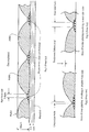
- US 6,235,177 (Aerogen) describes an approach based on electroplating, in which a wafer material is built onto a mandrel by a process of electro-deposition where the liquefied metals in the plating bath (typically Palladium and Nickel) are transferred from the liquid form to the solid form on the wafer. Material is transferred to the conducting surface on the mandrel and not to the photo resist areas which are non-conducting. Areas are masked with non-conductive photo resist where metallic build-up is not required, see Fig. 1 . After the conclusion of the plating process, the mandrel/wafer assembly is removed from the bath and the wafer peeled from the mandrel for subsequent processing into an aperture plate.
- the liquefied metals in the plating bath typically Palladium and Nickel
- a problem with this approach is that the hole size is dependent on the plating time and the thickness of the resulting wafer.
- the process can be difficult to control, and if not perfectly controlled some holes may be near closed or blocked as shown in Fig 2 , or over-sized as shown in Fig 3 , and there may be out-of-tolerance variation in the sizes of the holes.
- an increase in output rate usually requires an increase in particle size, which generally may not be desired. It is more desired to increase output rate without increasing particle size.
- Combinations of hole size accuracy and number of holes per unit of area can be a significant determinant in the nebulizer output rate and resulting particle size distribution.
- WO2011/139233 (Agency for Science, Technology and Research) describes a microsieve manufactured using SU8 material with photo-masking.
- US4844778 (Stork Veco) describes manufacture of a membrane for separating media, and a separation device incorporating such a membrane.
- the manufacturing method includes a two step photolithographic procedure.
- EP1199382 (Citizen watch Co. Ltd.) describes a production method for a hole structure in which there is exposure to photosensitive material in multiple cycles to provide deeper holes tapered towards the top because there is exposure through the first holes.
- the invention is directed towards providing an improved method for manufacture of an aperture plate for a nebulizer to address the above problems.
- an aerosol-forming aperture plate wafer comprising:
- All of the mask of all cycles may be removed together in some embodiments, however, in other embodiments the mask of one cycle may be removed before the subsequent cycle of masking and plating, and if so the subsequent plating is more likely to at least partly in-fill some of the lower holes.
- the columns have a depth in the range of 5 ⁇ m to 40 ⁇ m, and preferably 15 ⁇ m to 25 ⁇ m. In some embodiments, the columns have a width dimension in the plane of the mandrel in the range of 1 ⁇ m to 10 ⁇ m, preferably 2 ⁇ m to 6 ⁇ m.
- the electroplating is continued until the plated material is substantially flush with the tops of the columns.
- the at least one subsequent cycle brings the overall wafer thickness up to above 50 ⁇ m, and preferably greater than 58 ⁇ m. In one embodiment, the extent of occlusion in the or each subsequent cycle is chosen for desired mechanical properties of the aperture plate.
- the first masking and plating are performed so that the aerosol-forming holes are tapered in a funnel-shape.
- the subsequent masking and plating are performed so that the overlay spaces are tapered in a funnel shape.
- the plated metal includes Ni and/or Pd. In one embodiment, the Ni and/or Pd are present at a surface at a concentration chosen for anti-corrosion properties. In one embodiment, the proportion of Pd is in the range of 85% w/w and 93% w/w, and preferably about 89%, substantially the balance being Ni. In one embodiment, the plated material includes Ag and/or or Cu at a surface, at a concentration chosen for anti-bacterial properties.
- the method comprises the further steps of further processing the wafer to provide an aperture plate ready to fit into an aerosol-forming device.
- the wafer is formed into a non-planar shaped aperture plate.
- the wafer is formed into a shape with a configuration chosen according to desired aerosolizing spray angles.
- the wafer is formed into a shape having an operative dome-shaped part and a flange for engaging a drive.
- the wafer is annealed before being formed.
- the invention provides an aperture plate wafer comprising a body of metal whenever formed in a method as defined above in any embodiment.
- the invention provides an aperture plate whenever formed by a method as defined above in any embodiment.
- the invention provides an aperture plate wafer comprising a bottom layer of photolithography-plated metal with aerosol-forming through holes and at least one top layer of photolithography-plated metal having spaces, in which said spaces overlie a plurality of aerosol-forming through holes, in which the size and number of aerosol-forming holes per large hole is related to a desired aerosol flow rate
- the top layer occludes some of the holes in the bottom layer.
- the metal of all layers is the same.
- the plated metal includes Ni and/or Pd. In one embodiment, the Ni and/or Pd are present at a surface at a concentration chosen for anti-corrosion properties.
- the proportion of Pd is in the range of 85% w/w and 93% w/w, and preferably about 89%, substantially the balance being Ni.
- the plated metal includes Ag and/or or Cu at a surface, at a concentration chosen for anti-bacterial properties.
- the invention provides an aperture plate including a wafer as defined above in any embodiment.
- the invention provides an aerosol-forming device comprising an aperture plate as defined above in any embodiment, and a drive engaging the plate to vibrate it at a desired frequency for forming an aerosol.
- the invention provides an aerosol-forming device comprising an aperture plate as defined above in any embodiment, a support for the aperture plate for passive aperture plate use, and a horn arranged to force a wave of liquid through the aperture plate.
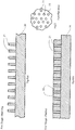
- a mandrel 20 has a photo-resist 21 applied in a pattern of vertical columns having the dimensions of holes or pores of the aperture plate to be produced.
- the column height is preferably in the range of 5 ⁇ m to 40 ⁇ m height, and more preferably 5 ⁇ m to 30 ⁇ m, and most preferably 15 ⁇ m to 25 ⁇ m.
- the diameter is preferably in the range of 1 ⁇ m to 10 ⁇ m, and most preferably about 2 ⁇ m to 6 ⁇ m diameter.
- This mask pattern provides the apertures which define the aerosol particle size. They are much greater in number per unit of area when compared to the prior art; a twenty-fold increase is possible, thus having up to 2500 holes per square mm.
- a second photo-resist mask 25 of much larger (wider and taller) columns, encompassing the area of a number of first columns 21.
- the hole diameter in the second plating layer is between 20 ⁇ m and 400 ⁇ m and more preferably between 40 ⁇ m and 150 ⁇ m. To ensure higher flow rates this diameter is produced at the upper end of the range, and to assure lower flow rates it is produced at the lower end of the range to close more of the smaller openings on the first layer.
- the spaces around the photo-resist 25 are plated to provide a wafer body 26 on the mandrel 20.
- the photo-resist 21 and 25 is cleaned with resist remover and rinsed away the plated material 22 and 26 is in the form of an aperture plate blank or mask 30, as shown in Fig. 8 , having large top apertures 32 and small bottom apertures 33.
- all of the resist 21 and 25 is removed together, however, it is envisaged that the resist 21 may be removed before the subsequent cycle of masking and plating. In this case the subsequent plating is more likely to at least partly in-fill some of the aerosol-forming apertures.
- the wafer 30 is punched into a disc and is formed into a dome shape to provide a final product aperture plate 40.
- the doming diameter may be selected to provide a desired spray angle and/or to set the optimum natural frequency for the drive controller.
- the dome shape provides a funnelling effect, and the particular shape of the domed plate affects the spray characteristics.
- the aperture plate is not domed, but is left planar, suitable for use in a device such as a passive plate nebulizer.
- a sonotrode or horn is placed in contact with the medication on the plate.
- a piezo element causes rapid movement of the transducer horn, which forces a wave of medication against the aperture plate causing a stream of medication to be filtered through the plate to the exit side as an aerosol.
- the mandrel 20 is coated with the photo resist 21 with a column height and width equal to the target hole dimension.
- This coating and subsequent ultraviolet (UV) development is such that columns 21 of photo-resist are left standing on the mandrel 20.
- These columns are of the required diameter and are as high as their rigidity will support.
- As the columns are only less than 10 ⁇ m, and preferably less than 6 ⁇ m in diameter it is possible to get many more columns and resulting holes per unit of area than in the prior art. It is expected that there may be as many as twenty times more holes than in the prior art electroplating approach. This creates potential for a substantial increase in the proportion of open area and resultant nebulizer output.
- the mandrel 20 with the selectively developed photo resist in the form of upstanding columns 21 is then placed in the plating bath and through the process of electro-deposition containing the metals Palladium Nickel (PdNi) in liquid form typically is then imparted to the surface.
- the plating activity is stopped when the height of the columns is reached. No over-plating is allowed as the plating is stopped just as it reaches the height of the columns of photo resist.
- the plating solution is chosen to suit the desired aperture plate dimensions and operating parameters such as vibration frequency.
- the Pd proportion may be in the range of about 85% to 93% w/w, and in one embodiment is about 89% w/w, the balance being substantially all Ni.
- the plated structure preferably has a fine randomly equiaxed grain microstructure, with a grain size from 0.2 ⁇ m to 2.0 ⁇ m for example.
- a fine randomly equiaxed grain microstructure with a grain size from 0.2 ⁇ m to 2.0 ⁇ m for example.
- Those skilled in the electo-deposition field art will appreciate how plating conditions for both plating stages may be chosen to suit the circumstances, and the entire contents of the following documents are herein incorporated by reference: US4628165 , US6235117 , US2007023547 , US2001013554 , WO2009/042187 , and Lu S. Y., Li J. F., Zhou Y. H., "Grain refinement in the solidification of undercooled Ni-Pd alloys", Journal of Crystal Growth 309 (2007) 103-111, Sept 14 2007 .
- the wafer thickness is typically 5 - 40 ⁇ m depending on the height of the columns. Peeling off the wafer at this point would yield a very thin wafer in comparison to the standard 60 ⁇ m thickness of the prior art. A wafer of this thickness would lack rigidity, be very difficult to process, and would require complex and expensive changes to the mechanical fabrication of the nebulizer core to achieve a natural frequency equivalent to the state of the art such that the existing electronic control drivers would be useable, which in some cases are integrated into ventilators. Use of a different drive controller would be a significant economic barrier to market acceptance due to the costs involved.
- the photo resist thickness is placed to a depth equal to that required to bring the overall wafer thickness to approximately 60 ⁇ m (similar to the prior art wafer thickness).
- the second mask height is preferably in the range of 40 - 50 ⁇ m for many applications. It is then developed to allow larger columns to stand on the plated surface. These are typically of a diameter between 40 - 100 ⁇ m but could be larger or smaller.
- the additional height from the second plating aids removal from the mandrel, but importantly it also achieves a particular thickness which is equivalent to the prior art aperture plate thickness to allow the end product aperture plate 40 to be electrically driven by the existing controllers on the market.
- the second plating stage provides a thickness more suited to the nebulizer application for rigidity, flexibility and flexural strength. Another aspect is that it occludes some of the smaller holes, thereby achieving improved control over flow rate.
- the second masking and plating stage can be used to "tune" the end product aperture plate according to desired flow rate. Also, it may be rapidly changed between small batches to enable a wide range of differently tuned plates.
- the wafer is then carefully peeled from the substrate without the aid of any subsequent processes such as etching or laser cutting. This ease of peeling has the advantages of not imparting additional mechanical stresses into an already brittle wafer.
- the wafer is then washed and rinsed in photo-resist remover prior to metrology inspection.
- the holes 33 have a depth equal to the first plating layer and the final wafer thickness will be equal to the sum of both plating layers, see Figs 8 and 9 . It is then ready for annealing, punching and doming to form the vibrating plate 40 shown in Fig. 9 .
- the membrane may be of an electroformed Ni substrate material that is over-plated with corrosion-resistant materials such as Copper, Silver, Palladium, Platinum and/or PdNi alloys. Copper and silver advantageously have bacteria-resistant properties.
- the invention provides an aperture plate having a first layer of electroformed metal with a plurality of aerosol-forming through holes which defines the droplet size being ejected and a second top layer of similar or dis-similar electroformed material with larger diameter holes or spaces above the aerosol-forming holes and the plating material of which occlude some of the first layer holes.
- the second layer has a number of holes or spaces with diameters chosen such that a pre-determined number of droplet size forming first layer holes are exposed, which determines the number of active holes and thus defines the quantity of liquid being aerosolised per unit of time
- the size and number of holes in both layers can be independently varied to achieve the desired ranges of droplet size and flow rate distribution, which is not possible with the prior art plating defined technology.
- the invention provides the potential for a much greater number of holes per unit of area when compared to the prior art. For example a twenty-fold increase is possible, thus having up to 2500 holes per square mm.
- the second layer at least completely or partly inter-fills some of the aerosol-forming holes in the first layer, thus forming mechanical anchorage of both layers to help achieve endurance life requirements.
- Figs. 11 to 14 in a second embodiment the processing is much the same as for the above embodiment.
- both of the sets of photo-resist columns are tapered so that the resultant holes are tapered for improved flow of aerosol liquid.
- the second mask comprises tapered columns 55, and the spaces in-between are plated with metal 56. Greater care is required for the plating steps to ensure that there is adequate plating under the mask overhangs.
- Fig. 14 shows a plan view, in this case after removal of the photo resist. It will be seen that there are several small holes 61 for each large top hole 65 in the PdNi body 56/52.
- the top hole 65 has the effect of a funnel down to the small holes 61, which themselves are funnel-shaped.
- the invention is not limited to the embodiments described but may be varied in construction and detail.
- the second cycle of masking and plating may not be required if the wafer can be removed from the mandrel, either due to the required wafer depth being achieved in the first stage or due to improved wafer-removal technologies being available.
- a third layer could be applied to provide more mechanical rigidity to the aperture plate.
- the layers are of the same metal. However it is envisaged that they may be different, and indeed the metal within each hole-forming layer may include sub-layers of different metals. For example the composition at one or both surfaces may be different for greater corrosion resistance and/or certain hydrophilic or hydrophobic properties. Also, there may be an additional plating step for the top 1 to 5 ⁇ m or 1 to 3 ⁇ m surface layer.
Landscapes
- Chemical & Material Sciences (AREA)
- Engineering & Computer Science (AREA)
- Organic Chemistry (AREA)
- Metallurgy (AREA)
- Materials Engineering (AREA)
- Electrochemistry (AREA)
- Chemical Kinetics & Catalysis (AREA)
- Health & Medical Sciences (AREA)
- Hematology (AREA)
- Biomedical Technology (AREA)
- Veterinary Medicine (AREA)
- General Health & Medical Sciences (AREA)
- Animal Behavior & Ethology (AREA)
- Life Sciences & Earth Sciences (AREA)
- Heart & Thoracic Surgery (AREA)
- Public Health (AREA)
- Anesthesiology (AREA)
- Dispersion Chemistry (AREA)
- Electroplating Methods And Accessories (AREA)
- Electroplating And Plating Baths Therefor (AREA)
- Printing Elements For Providing Electric Connections Between Printed Circuits (AREA)
- Chemically Coating (AREA)
Applications Claiming Priority (3)
| Application Number | Priority Date | Filing Date | Title |
|---|---|---|---|
| US201261658054P | 2012-06-11 | 2012-06-11 | |
| PCT/EP2013/060803 WO2013186031A2 (en) | 2012-06-11 | 2013-05-24 | A method of producing an aperture plate for a nebulizer |
| EP13726161.6A EP2859137B1 (en) | 2012-06-11 | 2013-05-24 | A method of producing an aperture plate for a nebulizer |
Related Parent Applications (1)
| Application Number | Title | Priority Date | Filing Date |
|---|---|---|---|
| EP13726161.6A Division EP2859137B1 (en) | 2012-06-11 | 2013-05-24 | A method of producing an aperture plate for a nebulizer |
Publications (1)
| Publication Number | Publication Date |
|---|---|
| EP3476982A1 true EP3476982A1 (en) | 2019-05-01 |
Family
ID=48539126
Family Applications (2)
| Application Number | Title | Priority Date | Filing Date |
|---|---|---|---|
| EP18208663.7A Pending EP3476982A1 (en) | 2012-06-11 | 2013-05-24 | A method of producing an aperture plate for a nebulizer |
| EP13726161.6A Active EP2859137B1 (en) | 2012-06-11 | 2013-05-24 | A method of producing an aperture plate for a nebulizer |
Family Applications After (1)
| Application Number | Title | Priority Date | Filing Date |
|---|---|---|---|
| EP13726161.6A Active EP2859137B1 (en) | 2012-06-11 | 2013-05-24 | A method of producing an aperture plate for a nebulizer |
Country Status (7)
| Country | Link |
|---|---|
| US (4) | US9981090B2 (enExample) |
| EP (2) | EP3476982A1 (enExample) |
| JP (3) | JP6385922B2 (enExample) |
| CN (1) | CN104350182B (enExample) |
| BR (1) | BR112014027624B1 (enExample) |
| RU (1) | RU2637737C2 (enExample) |
| WO (1) | WO2013186031A2 (enExample) |
Cited By (1)
| Publication number | Priority date | Publication date | Assignee | Title |
|---|---|---|---|---|
| EP4032619A1 (en) * | 2021-01-25 | 2022-07-27 | Korea Institute of Science and Technology | Mesh type atomizer using porous thin film and method for manufacturing the same |
Families Citing this family (35)
| Publication number | Priority date | Publication date | Assignee | Title |
|---|---|---|---|---|
| EP2658719B1 (en) * | 2010-12-28 | 2018-08-29 | Stamford Devices Limited | Photodefined aperture plate and method for producing the same |
| EP3476982A1 (en) | 2012-06-11 | 2019-05-01 | Stamford Devices Limited | A method of producing an aperture plate for a nebulizer |
| EP2886185A1 (en) * | 2013-12-20 | 2015-06-24 | Activaero GmbH | Perforated membrane and process for its preparation |
| EP2947181B1 (en) | 2014-05-23 | 2017-02-22 | Stamford Devices Limited | A method for producing an aperture plate |
| WO2015177311A1 (en) | 2014-05-23 | 2015-11-26 | Stamford Devices Limited | A method for producing an aperture plate |
| US10518288B2 (en) | 2015-06-10 | 2019-12-31 | Stamford Devices Limited | Aerosol generation |
| EP3452152B1 (en) | 2016-05-03 | 2025-07-02 | Pneuma Respiratory, Inc. | A droplet delivery device for generating and delivering droplets to the pulmonary system |
| EP3452150B1 (en) | 2016-05-03 | 2024-01-17 | Pneuma Respiratory, Inc. | Droplet delivery device for delivery of fluids to the pulmonary system |
| WO2017192774A1 (en) | 2016-05-03 | 2017-11-09 | Pneuma Respiratory, Inc. | Methods for the systemic delivery of therapeutic agents to the pulmonary system using a droplet delivery device |
| WO2017192782A1 (en) | 2016-05-03 | 2017-11-09 | Pneuma Respiratory, Inc. | Systems and methods comprising a droplet delivery device and a breathing assist device for therapeutic treatment |
| WO2017192773A1 (en) | 2016-05-03 | 2017-11-09 | Pneuma Respiratory, Inc. | Methods for treatment of pulmonary lung diseases with improved therapeutic efficacy and improved dose efficiency |
| KR101953970B1 (ko) * | 2016-06-29 | 2019-03-05 | 동국대학교 경주캠퍼스 산학협력단 | 미세분무용 다공성 필터의 제조방법 및 이를 이용하여 제조된 다공성 필터 |
| ES2987903T3 (es) * | 2017-03-23 | 2024-11-18 | Stamford Devices Ltd | Sistema de administración de aerosol |
| EP4223335A3 (en) | 2017-05-19 | 2023-11-08 | Pneuma Respiratory, Inc. | Dry powder delivery device and methods of use |
| JP2020536614A (ja) | 2017-10-04 | 2020-12-17 | ニューマ・リスパイラトリー・インコーポレイテッド | 呼吸により電気的に作動するインライン液滴送達装置および使用方法 |
| CA3079189A1 (en) | 2017-10-17 | 2019-04-25 | Pneuma Respiratory, Inc. | Nasal drug delivery apparatus and methods of use |
| JP2021502178A (ja) | 2017-11-08 | 2021-01-28 | ニューマ・リスパイラトリー・インコーポレイテッド | 小容積アンプルを有して呼吸により電気的に作動するインライン液滴送達装置および使用方法 |
| WO2019115221A1 (en) | 2017-12-14 | 2019-06-20 | Stamford Devices Limited | Mounting of an aerosol generator aperture plate to a support |
| JP6973051B2 (ja) * | 2017-12-26 | 2021-11-24 | 株式会社リコー | 液体吐出ヘッド、液体吐出ユニット、液体を吐出する装置 |
| JP7495356B2 (ja) * | 2018-05-16 | 2024-06-04 | フィリップ・モーリス・プロダクツ・ソシエテ・アノニム | アトマイザー組立品用の二層メッシュ要素 |
| US11173258B2 (en) | 2018-08-30 | 2021-11-16 | Analog Devices, Inc. | Using piezoelectric electrodes as active surfaces for electroplating process |
| WO2020145096A1 (ja) * | 2019-01-07 | 2020-07-16 | 株式会社村田製作所 | 濾過フィルタ |
| CN110055567B (zh) * | 2019-04-18 | 2021-05-07 | 中国科学院化学研究所 | 微孔膜材料的电沉积制备方法和微孔膜材料及其应用 |
| CN115362029A (zh) | 2020-03-24 | 2022-11-18 | 斯坦福设备有限公司 | 振动孔板雾化器 |
| WO2022013088A1 (en) | 2020-07-14 | 2022-01-20 | Stamford Devices Limited | A vaccine administration apparatus and method |
| EP4088822A1 (en) * | 2021-05-12 | 2022-11-16 | PARI Pharma GmbH | Nebulizing device for an inhalator |
| PL4359046T3 (pl) | 2021-06-22 | 2025-10-13 | Pneuma Respiratory, Inc. | Urządzenie do podawania kropelkowego z wyrzutem wypychającym |
| CN113733380B (zh) * | 2021-08-30 | 2024-06-07 | 深圳市长龙点金科技有限公司 | 一种增强贵金属覆盖效率的胶粒结构 |
| EP4197646A1 (en) | 2021-12-17 | 2023-06-21 | Stamford Devices Limited | A nebulizer with plume detection |
| US20250058059A1 (en) | 2021-12-17 | 2025-02-20 | Stamford Devices Limited | A nebulizer with plume detection |
| US12161795B2 (en) | 2022-07-18 | 2024-12-10 | Pneuma Respiratory, Inc. | Small step size and high resolution aerosol generation system and method |
| WO2024094429A1 (en) | 2022-11-03 | 2024-05-10 | Stamford Devices Limited | A method of manufacturing nebuliser aperture plates |
| KR20250121011A (ko) * | 2022-12-14 | 2025-08-11 | 필립모리스 프로덕츠 에스.에이. | 진동 메쉬 모듈용 멤브레인 |
| WO2025242695A1 (en) | 2024-05-21 | 2025-11-27 | Stamford Devices Limited | A nebulizer aperture plate and method of manufacture |
| WO2026046936A1 (en) | 2024-08-28 | 2026-03-05 | Stamford Devices Limited | Nebulizer reservoir aperture plates and their manufacture |
Citations (13)
| Publication number | Priority date | Publication date | Assignee | Title |
|---|---|---|---|---|
| DE1948135A1 (de) * | 1969-09-23 | 1971-04-01 | Siemens Ag | Verfahren zur Herstellung von Siebdruckschablonen aus Metallen |
| DE2050285A1 (en) * | 1970-10-13 | 1972-05-25 | Siemens Ag | Screen printing plate - produced using intermediate photo-sensitive polymeric foil |
| US4184925A (en) * | 1977-12-19 | 1980-01-22 | The Mead Corporation | Solid metal orifice plate for a jet drop recorder |
| US4379737A (en) * | 1981-11-18 | 1983-04-12 | Armstrong World Industries, Inc. | Method to make a built up area rotary printing screen |
| US4628165A (en) | 1985-09-11 | 1986-12-09 | Learonal, Inc. | Electrical contacts and methods of making contacts by electrodeposition |
| US4844778A (en) | 1986-12-23 | 1989-07-04 | Stork Veco B.V. | Membrane with perforations, method for producing such a membrane and separating device comprising one or more of such membranes |
| JPH11138827A (ja) * | 1997-11-10 | 1999-05-25 | Citizen Watch Co Ltd | 微細部品の製造方法 |
| US6235177B1 (en) | 1999-09-09 | 2001-05-22 | Aerogen, Inc. | Method for the construction of an aperture plate for dispensing liquid droplets |
| US6235117B1 (en) | 1998-11-06 | 2001-05-22 | Eamon P. McDonald | Squeegee roll for thin sheet handling system |
| EP1199382A1 (en) | 2000-03-22 | 2002-04-24 | Citizen Watch Co. Ltd. | Hole structure and production method for hole structure |
| WO2009042187A1 (en) | 2007-09-25 | 2009-04-02 | Nektar Therapeutics | Treatment of pulmonary disorders with aerosolized medicaments such as vancomycin |
| WO2011083380A1 (en) * | 2010-01-11 | 2011-07-14 | Koninklijke Philips Electronics N.V. | Magnetic coupling for aerosol generating apparatus |
| WO2011139233A1 (en) | 2010-05-04 | 2011-11-10 | Agency For Science, Technology And Research | A microsieve for cells and particles filtration |
Family Cites Families (80)
| Publication number | Priority date | Publication date | Assignee | Title |
|---|---|---|---|---|
| US2226706A (en) | 1937-11-29 | 1940-12-31 | Hazeltine Corp | Periodic wave-generating system |
| US3130487A (en) | 1962-12-17 | 1964-04-28 | Norman B Mears | Method of making fine mesh dome-shaped grids |
| US3325319A (en) * | 1963-12-18 | 1967-06-13 | Buckbee Mears Co | Process for etching arcuately shaped metal sheets |
| US4430784A (en) | 1980-02-22 | 1984-02-14 | Celanese Corporation | Manufacturing process for orifice nozzle devices for ink jet printing apparati |
| US4849303A (en) * | 1986-07-01 | 1989-07-18 | E. I. Du Pont De Nemours And Company | Alloy coatings for electrical contacts |
| US4773971A (en) | 1986-10-30 | 1988-09-27 | Hewlett-Packard Company | Thin film mandrel |
| US4839001A (en) * | 1988-03-16 | 1989-06-13 | Dynamics Research Corporation | Orifice plate and method of fabrication |
| US4972204A (en) | 1989-08-21 | 1990-11-20 | Eastman Kodak Company | Laminate, electroformed ink jet orifice plate construction |
| DE3928832C2 (de) | 1989-08-31 | 1995-04-20 | Blasberg Oberflaechentech | Verfahren zur Herstellung von durchkontaktierten Leiterplatten und Leiterplatten-Halbzeug |
| US5152456A (en) * | 1989-12-12 | 1992-10-06 | Bespak, Plc | Dispensing apparatus having a perforate outlet member and a vibrating device |
| JP2992645B2 (ja) | 1990-11-19 | 1999-12-20 | 九州日立マクセル株式会社 | 透孔を有する電鋳製品の製造方法 |
| AU9089591A (en) | 1990-12-17 | 1992-07-22 | Minnesota Mining And Manufacturing Company | Inhaler |
| JP2723690B2 (ja) * | 1991-04-22 | 1998-03-09 | 耕司 戸田 | 超音波カラーオルガン |
| US5164740A (en) | 1991-04-24 | 1992-11-17 | Yehuda Ivri | High frequency printing mechanism |
| US6629646B1 (en) | 1991-04-24 | 2003-10-07 | Aerogen, Inc. | Droplet ejector with oscillating tapered aperture |
| JPH05177834A (ja) | 1991-06-04 | 1993-07-20 | Seiko Epson Corp | インクジェット記録ヘッド |
| US5180482A (en) * | 1991-07-22 | 1993-01-19 | At&T Bell Laboratories | Thermal annealing of palladium alloys |
| JPH0574669A (ja) | 1991-09-18 | 1993-03-26 | Rohm Co Ltd | 半導体装置の製造方法 |
| JP3200923B2 (ja) | 1992-03-02 | 2001-08-20 | 株式会社村田製作所 | エレクトロフォーミング方法 |
| JP2544634Y2 (ja) * | 1992-03-10 | 1997-08-20 | ティーディーケイ株式会社 | 超音波霧化器 |
| JPH07329304A (ja) | 1994-04-11 | 1995-12-19 | Fujitsu Ltd | インクジェット記録装置、その記録ヘッド用ノズル板およびそのノズル板の製造方法 |
| US5565113A (en) | 1994-05-18 | 1996-10-15 | Xerox Corporation | Lithographically defined ejection units |
| US5443713A (en) | 1994-11-08 | 1995-08-22 | Hewlett-Packard Corporation | Thin-film structure method of fabrication |
| US5560837A (en) * | 1994-11-08 | 1996-10-01 | Hewlett-Packard Company | Method of making ink-jet component |
| US5685491A (en) * | 1995-01-11 | 1997-11-11 | Amtx, Inc. | Electroformed multilayer spray director and a process for the preparation thereof |
| WO1996030645A1 (de) | 1995-03-29 | 1996-10-03 | Robert Bosch Gmbh | Verfahren zur herstellung einer lochscheibe |
| EP0787255B1 (de) * | 1995-03-29 | 2002-07-31 | Robert Bosch Gmbh | Lochscheibe, inbesondere für einspritzventile |
| BR9605943A (pt) | 1995-03-29 | 1997-08-19 | Bosch Gmbh Robert | Disco perfurado particularmente para válvulas de injeção |
| US6205999B1 (en) * | 1995-04-05 | 2001-03-27 | Aerogen, Inc. | Methods and apparatus for storing chemical compounds in a portable inhaler |
| US5586550A (en) | 1995-08-31 | 1996-12-24 | Fluid Propulsion Technologies, Inc. | Apparatus and methods for the delivery of therapeutic liquids to the respiratory system |
| US6427682B1 (en) * | 1995-04-05 | 2002-08-06 | Aerogen, Inc. | Methods and apparatus for aerosolizing a substance |
| US5758637A (en) | 1995-08-31 | 1998-06-02 | Aerogen, Inc. | Liquid dispensing apparatus and methods |
| MX9601409A (es) * | 1995-04-14 | 1997-08-30 | Canon Kk | Metodo para producir una cabeza de eyeccion de liquido y cabeza de eyeccion de liquido obtenida por dicho metodo. |
| DE19527846A1 (de) | 1995-07-29 | 1997-01-30 | Bosch Gmbh Robert | Ventil, insbesondere Brennstoffeinspritzventil |
| US5837960A (en) | 1995-08-14 | 1998-11-17 | The Regents Of The University Of California | Laser production of articles from powders |
| DE19639506A1 (de) | 1996-09-26 | 1998-04-02 | Bosch Gmbh Robert | Lochscheibe und Ventil mit einer Lochscheibe |
| JP3934723B2 (ja) * | 1997-02-13 | 2007-06-20 | 株式会社オプトニクス精密 | メタルマスクの製造方法 |
| JP2001505279A (ja) | 1997-09-16 | 2001-04-17 | ローベルト ボツシユ ゲゼルシヤフト ミツト ベシユレンクテル ハフツング | 孔付円板もしくは霧化円板並びに孔付円板もしくは霧化円板を備えた噴射弁 |
| US6310641B1 (en) | 1999-06-11 | 2001-10-30 | Lexmark International, Inc. | Integrated nozzle plate for an inkjet print head formed using a photolithographic method |
| US6357677B1 (en) | 1999-10-13 | 2002-03-19 | Siemens Automotive Corporation | Fuel injection valve with multiple nozzle plates |
| ATE354430T1 (de) * | 1999-12-08 | 2007-03-15 | Baxter Int | Verfahren zur herstellung einer mikroporösen filtermembran |
| KR100421774B1 (ko) * | 1999-12-16 | 2004-03-10 | 앰코 테크놀로지 코리아 주식회사 | 반도체패키지 및 그 제조 방법 |
| JP4527250B2 (ja) | 2000-07-10 | 2010-08-18 | 九州日立マクセル株式会社 | ノズル体の製造方法 |
| US6586112B1 (en) | 2000-08-01 | 2003-07-01 | Hewlett-Packard Company | Mandrel and orifice plates electroformed using the same |
| JP3751523B2 (ja) * | 2000-11-30 | 2006-03-01 | 三菱電機株式会社 | 液滴吐出装置 |
| JP4671255B2 (ja) | 2000-12-20 | 2011-04-13 | 九州日立マクセル株式会社 | 電鋳製メタルマスクの製造方法 |
| JP2002289097A (ja) | 2001-03-23 | 2002-10-04 | Sumitomo Metal Mining Co Ltd | アパチャーグリルの製造方法 |
| AU2002360464A1 (en) | 2001-12-03 | 2003-06-17 | Memgen Corporation | Miniature rf and microwave components and methods for fabricating such components |
| WO2003059424A1 (en) * | 2002-01-15 | 2003-07-24 | Aerogen, Inc. | Methods and systems for operating an aerosol generator |
| TW589253B (en) | 2002-02-01 | 2004-06-01 | Nanodynamics Inc | Method for producing nozzle plate of ink-jet print head by photolithography |
| US8245708B2 (en) | 2002-05-07 | 2012-08-21 | The Research Foundation Of State University Of New York | Methods, devices and formulations for targeted endobronchial therapy |
| KR100510124B1 (ko) | 2002-06-17 | 2005-08-25 | 삼성전자주식회사 | 잉크제트 프린트 헤드의 제조 방법 |
| JP2004290426A (ja) | 2003-03-27 | 2004-10-21 | Mitsubishi Materials Corp | 超音波式吸入器用メッシュ |
| JP2006056151A (ja) | 2004-08-20 | 2006-03-02 | Alps Electric Co Ltd | クリーム半田印刷装置 |
| KR100624692B1 (ko) | 2004-09-13 | 2006-09-15 | 삼성전자주식회사 | 잉크젯 헤드용 필터 플레이트, 상기 필터 플레이트를구비하는 잉크젯 헤드 및 상기 필터 플레이트의 제조방법 |
| JP3723201B1 (ja) | 2004-10-18 | 2005-12-07 | 独立行政法人食品総合研究所 | 貫通孔を有する金属製基板を用いたマイクロスフィアの製造方法 |
| US7097776B2 (en) | 2004-10-22 | 2006-08-29 | Hewlett-Packard Development Company, L.P. | Method of fabricating microneedles |
| US7104475B2 (en) | 2004-11-05 | 2006-09-12 | Visteon Global Technologies, Inc. | Low pressure fuel injector nozzle |
| JP2006150993A (ja) | 2004-11-25 | 2006-06-15 | Kinugawa Rubber Ind Co Ltd | 自動車用ウエザーストリップ |
| US7501228B2 (en) | 2005-03-10 | 2009-03-10 | Eastman Kodak Company | Annular nozzle structure for high density inkjet printheads |
| JP2006297226A (ja) * | 2005-04-18 | 2006-11-02 | Sumitomo Electric Ind Ltd | 噴霧器用メッシュノズルおよび噴霧器 |
| JP2006297688A (ja) | 2005-04-19 | 2006-11-02 | Matsushita Electric Ind Co Ltd | ノズル板の製造方法、そのノズル板の製造方法を用いたノズル板およびそのノズル板を用いたインクジェットヘッド |
| JP4689340B2 (ja) | 2005-05-02 | 2011-05-25 | キヤノン株式会社 | 吐出用液体医薬組成物 |
| EP1896662B1 (en) | 2005-05-25 | 2014-07-23 | AeroGen, Inc. | Vibration systems and methods |
| JP2007245364A (ja) | 2006-03-13 | 2007-09-27 | Fujifilm Corp | ノズルプレートの製造方法及び液滴吐出ヘッド並びに画像形成装置 |
| EP1835050A1 (fr) * | 2006-03-15 | 2007-09-19 | Doniar S.A. | Procédé de fabrication par LIGA-UV d'une structure métallique multicouche à couches adjacentes non entièrement superposées, et structure obtenue |
| US8991389B2 (en) | 2006-04-20 | 2015-03-31 | Ric Investments, Llc | Drug solution level sensor for an ultrasonic nebulizer |
| US20080023572A1 (en) | 2006-07-28 | 2008-01-31 | Nalux Co., Ltd. | Porous plate with micro openings, method of producing the same, and atomizer having the same |
| JP2009195669A (ja) | 2008-01-25 | 2009-09-03 | Canon Inc | 薬剤吐出装置及びその制御方法 |
| US20100055045A1 (en) * | 2008-02-26 | 2010-03-04 | William Gerhart | Method and system for the treatment of chronic obstructive pulmonary disease with nebulized anticholinergic administrations |
| WO2010011329A2 (en) | 2008-07-23 | 2010-01-28 | Map Pharmaceuticals, Inc. | The delivery of powdered drug via inhalation |
| ITTO20080980A1 (it) | 2008-12-23 | 2010-06-24 | St Microelectronics Srl | Processo di fabbricazione di una membrana di ugelli integrata in tecnologia mems per un dispositivo di nebulizzazione e dispositivo di nebulizzazione che utilizza tale membrana |
| US7938522B2 (en) | 2009-05-19 | 2011-05-10 | Eastman Kodak Company | Printhead with porous catcher |
| US20110000481A1 (en) * | 2009-07-01 | 2011-01-06 | Anand Gumaste | Nebulizer for infants and respiratory compromised patients |
| EP2482901B1 (en) | 2009-09-30 | 2019-10-23 | Sanofi-Aventis Deutschland GmbH | Injection device |
| WO2012078589A1 (en) | 2010-12-07 | 2012-06-14 | Technic Inc. | Electro-depositing metal layers of uniform thickness |
| EP2658719B1 (en) | 2010-12-28 | 2018-08-29 | Stamford Devices Limited | Photodefined aperture plate and method for producing the same |
| EP3476982A1 (en) | 2012-06-11 | 2019-05-01 | Stamford Devices Limited | A method of producing an aperture plate for a nebulizer |
| GB2508558A (en) | 2014-03-17 | 2014-06-04 | Anthony Gibbons | Forming a perforate membrane by laser and reaming |
| WO2015177311A1 (en) | 2014-05-23 | 2015-11-26 | Stamford Devices Limited | A method for producing an aperture plate |
-
2013
- 2013-05-24 EP EP18208663.7A patent/EP3476982A1/en active Pending
- 2013-05-24 US US13/902,096 patent/US9981090B2/en active Active
- 2013-05-24 US US14/401,480 patent/US10512736B2/en active Active
- 2013-05-24 WO PCT/EP2013/060803 patent/WO2013186031A2/en not_active Ceased
- 2013-05-24 BR BR112014027624-2A patent/BR112014027624B1/pt active IP Right Grant
- 2013-05-24 JP JP2015515467A patent/JP6385922B2/ja active Active
- 2013-05-24 EP EP13726161.6A patent/EP2859137B1/en active Active
- 2013-05-24 CN CN201380030503.7A patent/CN104350182B/zh active Active
- 2013-05-24 RU RU2014145313A patent/RU2637737C2/ru active
-
2018
- 2018-06-25 JP JP2018119753A patent/JP2018158150A/ja active Pending
-
2019
- 2019-11-18 US US16/686,286 patent/US11679209B2/en active Active
-
2020
- 2020-02-13 JP JP2020022290A patent/JP6835991B2/ja active Active
-
2023
- 2023-05-09 US US18/314,637 patent/US20240001048A1/en active Pending
Patent Citations (15)
| Publication number | Priority date | Publication date | Assignee | Title |
|---|---|---|---|---|
| DE1948135A1 (de) * | 1969-09-23 | 1971-04-01 | Siemens Ag | Verfahren zur Herstellung von Siebdruckschablonen aus Metallen |
| DE2050285A1 (en) * | 1970-10-13 | 1972-05-25 | Siemens Ag | Screen printing plate - produced using intermediate photo-sensitive polymeric foil |
| US4184925A (en) * | 1977-12-19 | 1980-01-22 | The Mead Corporation | Solid metal orifice plate for a jet drop recorder |
| US4379737A (en) * | 1981-11-18 | 1983-04-12 | Armstrong World Industries, Inc. | Method to make a built up area rotary printing screen |
| US4628165A (en) | 1985-09-11 | 1986-12-09 | Learonal, Inc. | Electrical contacts and methods of making contacts by electrodeposition |
| US4844778A (en) | 1986-12-23 | 1989-07-04 | Stork Veco B.V. | Membrane with perforations, method for producing such a membrane and separating device comprising one or more of such membranes |
| JPH11138827A (ja) * | 1997-11-10 | 1999-05-25 | Citizen Watch Co Ltd | 微細部品の製造方法 |
| US6235117B1 (en) | 1998-11-06 | 2001-05-22 | Eamon P. McDonald | Squeegee roll for thin sheet handling system |
| US6235177B1 (en) | 1999-09-09 | 2001-05-22 | Aerogen, Inc. | Method for the construction of an aperture plate for dispensing liquid droplets |
| US20010013554A1 (en) | 1999-09-09 | 2001-08-16 | Scott Borland | Aperture plate and methods for its construction and use |
| US20070023547A1 (en) | 1999-09-09 | 2007-02-01 | Aerogen, Inc. | Aperture plate and methods for its construction and use |
| EP1199382A1 (en) | 2000-03-22 | 2002-04-24 | Citizen Watch Co. Ltd. | Hole structure and production method for hole structure |
| WO2009042187A1 (en) | 2007-09-25 | 2009-04-02 | Nektar Therapeutics | Treatment of pulmonary disorders with aerosolized medicaments such as vancomycin |
| WO2011083380A1 (en) * | 2010-01-11 | 2011-07-14 | Koninklijke Philips Electronics N.V. | Magnetic coupling for aerosol generating apparatus |
| WO2011139233A1 (en) | 2010-05-04 | 2011-11-10 | Agency For Science, Technology And Research | A microsieve for cells and particles filtration |
Non-Patent Citations (1)
| Title |
|---|
| LU S. Y.; LI J. F.; ZHOU Y. H.: "Grain refinement in the solidification of undercooled Ni-Pd alloys", JOURNAL OF CRYSTAL GROWTH, vol. 309, 14 September 2007 (2007-09-14), pages 103 - 111, XP022323988, DOI: doi:10.1016/j.jcrysgro.2007.09.005 |
Cited By (1)
| Publication number | Priority date | Publication date | Assignee | Title |
|---|---|---|---|---|
| EP4032619A1 (en) * | 2021-01-25 | 2022-07-27 | Korea Institute of Science and Technology | Mesh type atomizer using porous thin film and method for manufacturing the same |
Also Published As
| Publication number | Publication date |
|---|---|
| CN104350182A (zh) | 2015-02-11 |
| US9981090B2 (en) | 2018-05-29 |
| JP2015527481A (ja) | 2015-09-17 |
| US10512736B2 (en) | 2019-12-24 |
| JP2020096900A (ja) | 2020-06-25 |
| WO2013186031A3 (en) | 2014-07-24 |
| CN104350182B (zh) | 2020-04-21 |
| EP2859137B1 (en) | 2018-12-05 |
| JP6385922B2 (ja) | 2018-09-05 |
| RU2014145313A (ru) | 2016-07-27 |
| US20150101596A1 (en) | 2015-04-16 |
| BR112014027624B1 (pt) | 2021-01-19 |
| US11679209B2 (en) | 2023-06-20 |
| US20200078536A1 (en) | 2020-03-12 |
| BR112014027624A2 (pt) | 2017-08-22 |
| RU2637737C2 (ru) | 2017-12-06 |
| HK1205771A1 (en) | 2015-12-24 |
| EP2859137A2 (en) | 2015-04-15 |
| JP6835991B2 (ja) | 2021-02-24 |
| US20130334338A1 (en) | 2013-12-19 |
| JP2018158150A (ja) | 2018-10-11 |
| WO2013186031A2 (en) | 2013-12-19 |
| US20240001048A1 (en) | 2024-01-04 |
Similar Documents
| Publication | Publication Date | Title |
|---|---|---|
| US20240001048A1 (en) | Method of producing an aperture plate for a nebulizer | |
| US12565710B2 (en) | Photodefined aperture plate and method for producing the same | |
| EP2886185A1 (en) | Perforated membrane and process for its preparation | |
| JP6173824B2 (ja) | 開口プレートの製造方法 | |
| US11872573B2 (en) | Method for producing an aperture plate | |
| US9889261B2 (en) | Nebulizer mesh and production method thereof | |
| HK1205771B (zh) | 制造用於喷雾器的孔板的方法 | |
| EP2947181B1 (en) | A method for producing an aperture plate | |
| US7370416B2 (en) | Method of manufacturing an injector plate |
Legal Events
| Date | Code | Title | Description |
|---|---|---|---|
| PUAI | Public reference made under article 153(3) epc to a published international application that has entered the european phase |
Free format text: ORIGINAL CODE: 0009012 |
|
| STAA | Information on the status of an ep patent application or granted ep patent |
Free format text: STATUS: THE APPLICATION HAS BEEN PUBLISHED |
|
| AC | Divisional application: reference to earlier application |
Ref document number: 2859137 Country of ref document: EP Kind code of ref document: P |
|
| AK | Designated contracting states |
Kind code of ref document: A1 Designated state(s): AL AT BE BG CH CY CZ DE DK EE ES FI FR GB GR HR HU IE IS IT LI LT LU LV MC MK MT NL NO PL PT RO RS SE SI SK SM TR |
|
| STAA | Information on the status of an ep patent application or granted ep patent |
Free format text: STATUS: REQUEST FOR EXAMINATION WAS MADE |
|
| 17P | Request for examination filed |
Effective date: 20190702 |
|
| RBV | Designated contracting states (corrected) |
Designated state(s): AL AT BE BG CH CY CZ DE DK EE ES FI FR GB GR HR HU IE IS IT LI LT LU LV MC MK MT NL NO PL PT RO RS SE SI SK SM TR |
|
| STAA | Information on the status of an ep patent application or granted ep patent |
Free format text: STATUS: EXAMINATION IS IN PROGRESS |
|
| 17Q | First examination report despatched |
Effective date: 20210719 |